36
WEATHER PROOF INTELLI+ ® ACTUATORS SQ & ST RANGES by Reliability, Security, User Friendly. Invest in Confidence LABEL
WEATHER PROOF INTELLI+® ACTUATORS
SQ & ST RANGES
by
Reliability,
Security,
User Friendly.
Invest in Confidence
LAB
EL
LAB
EL
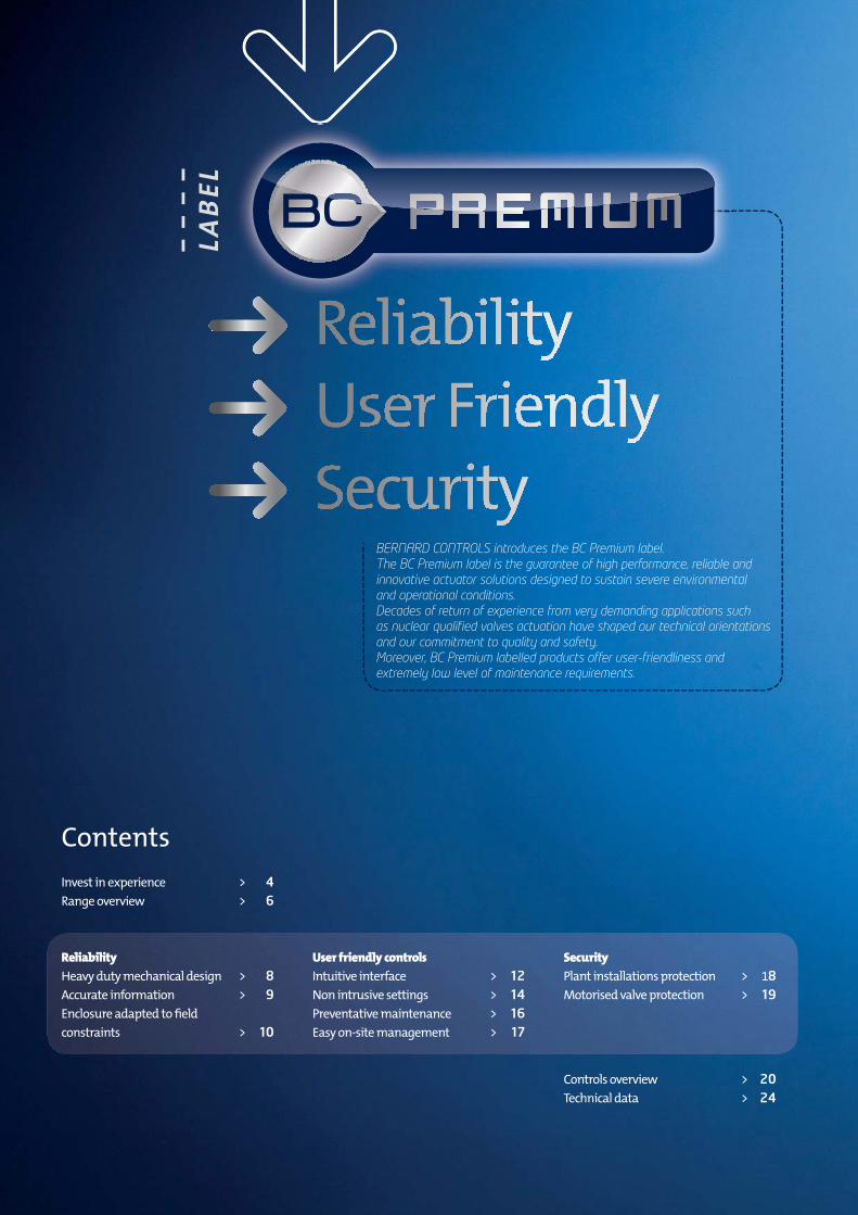
BERNARD CONTROLS introduces the BC Premium label.
The BC Premium label is the guarantee of high performance, reliable and
innovative actuator solutions designed to sustain severe environmental
and operational conditions.
Decades of return of experience from very demanding applications such
as nuclear qualifi ed valves actuation have shaped our technical orientations
and our commitment to quality and safety.
Moreover, BC Premium labelled products offer user-friendliness and
extremely low level of maintenance requirements.
Contents
Invest in experience > 4
Range overview > 6
Reliability
Heavy duty mechanical design > 8
Accurate information > 9
Enclosure adapted to fi eld
constraints > 10
User friendly controls
Intuitive interface > 12
Non intrusive settings > 14
Preventative maintenance > 16
Easy on-site management > 17
Security
Plant installations protection > 18
Motorised valve protection > 19
Controls overview > 20
Technical data > 24

Expertise and innovationExpertise is our business specialty. Our credo follows from the technical requirements of our
products’ fi elds of application. Our products are qualifi ed and approved by the largest prime
contractors and industrial players in France and abroad. By improving our competencies and
the effi ciency of our processes, we enhance the quality of our products and services.
Performance and SecurityThe nuclear market has shaped our expertise, our commitment to quality and to the control
of your processes. By fulfi lling these requirements, we undertake to make no compromise on
security.
Controls and Confi denceBERNARD CONTROLS is an international industrial technological company acknowledged for
its know-how and expertise in the most demanding markets. The control of processes is our
business and the cornerstone of your confi dence.
invest in
BERNARD CONTROLS RELIES ON 75 YEARS OF CONTINUOUS EXPERIENCE AND KNOW-HOW TO OFFER TOTAL & DURABLE SOLUTIONS FOR INDUSTRIAL VALVES’ AUTOMATION
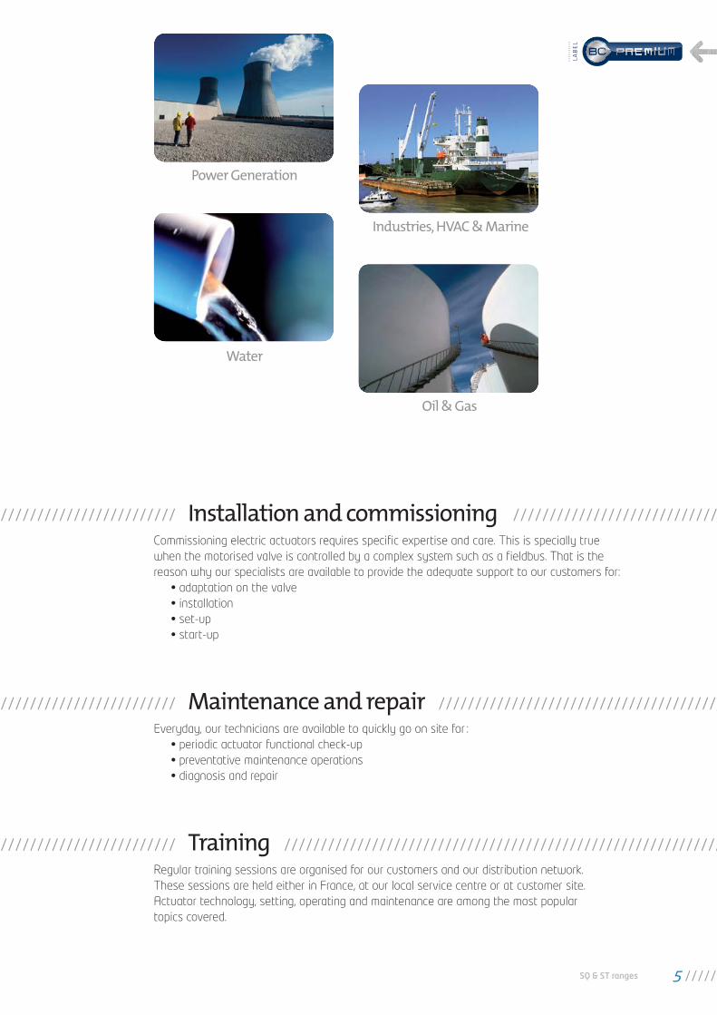
Installation and commissioningCommissioning electric actuators requires specifi c expertise and care. This is specially true
when the motorised valve is controlled by a complex system such as a fi eldbus. That is the
reason why our specialists are available to provide the adequate support to our customers for:
• adaptation on the valve
• installation
• set-up
• start-up
Maintenance and repairEveryday, our technicians are available to quickly go on site for :
• periodic actuator functional check-up
• preventative maintenance operations
• diagnosis and repair
TrainingRegular training sessions are organised for our customers and our distribution network.
These sessions are held either in France, at our local service centre or at customer site.
Actuator technology, setting, operating and maintenance are among the most popular
topics covered.
Power Generation
Industries, HVAC & Marine
Water
Oil & Gas
SQ & ST ranges 5
LAB
EL
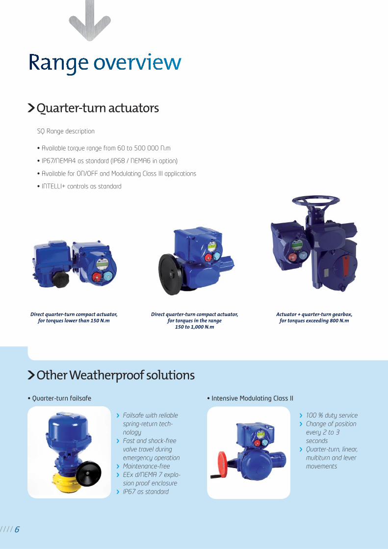
Quarter-turn actuators
SQ Range description
• Available torque range from 60 to 500 000 N.m
• IP67/NEMA4 as standard (IP68 / NEMA6 in option)
• Available for ON/OFF and Modulating Class III applications
• INTELLI+ controls as standard
Other Weatherproof solutions
• Quarter-turn failsafe
Failsafe with reliable
spring-return tech-
nology
Fast and shock-free
valve travel during
emergency operation
Maintenance-free
EEx d/NEMA 7 explo-
sion proof enclosure
IP67 as standard
• Intensive Modulating Class II
100 % duty service
Change of position
every 2 to 3
seconds
Quarter-turn, linear,
multiturn and lever
movements
6
Direct quarter-turn compact actuator,for torques lower than 150 N.m
Direct quarter-turn compact actuator,for torques in the range
150 to 1,000 N.m
Actuator + quarter-turn gearbox,for torques exceeding 800 N.m
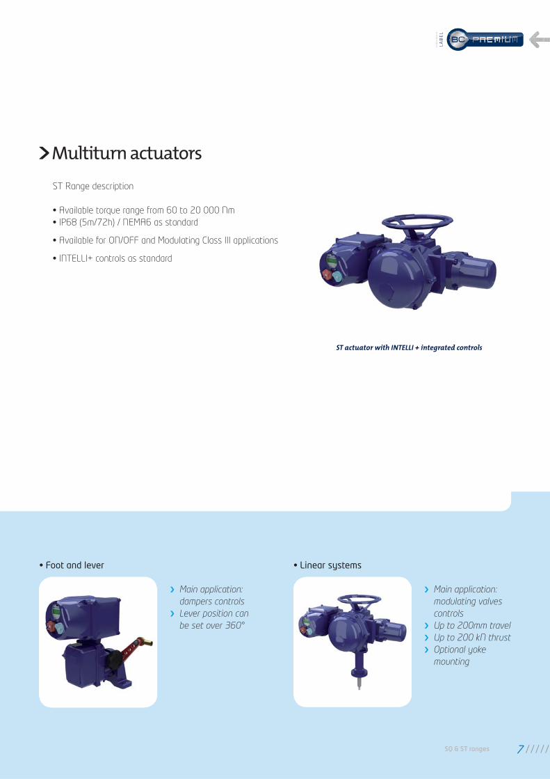
Multiturn actuators
ST Range description
• Available torque range from 60 to 20 000 Nm
• IP68 (5m/72h) / NEMA6 as standard
• Available for ON/OFF and Modulating Class III applications
• INTELLI+ controls as standard
• Foot and lever
Main application:
dampers controls
Lever position can
be set over 360°
• Linear systems
Main application:
modulating valves
controls
Up to 200mm travel
Up to 200 kN thrust
Optional yoke
mounting
ST actuator with INTELLI + integrated controls
SQ & ST ranges 7
LAB
EL
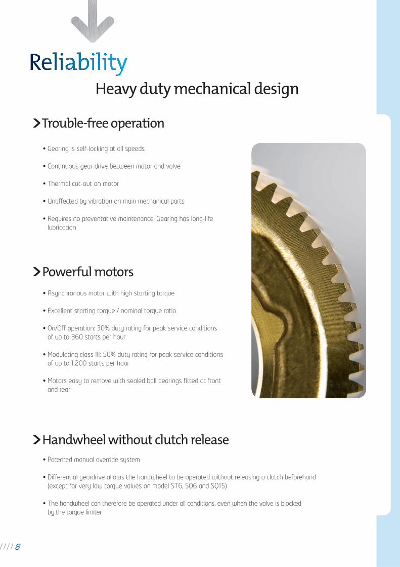
Heavy duty mechanical design
8
Powerful motors
• Gearing is self-locking at all speeds
• Continuous gear drive between motor and valve
• Thermal cut-out on motor
• Unaffected by vibration on main mechanical parts
• Requires no preventative maintenance. Gearing has long-life
lubrication
Trouble-free operation
• Asynchronous motor with high starting torque
• Excellent starting torque / nominal torque ratio
• On/Off operation: 30% duty rating for peak service conditions
of up to 360 starts per hour
• Modulating class III: 50% duty rating for peak service conditions
of up to 1,200 starts per hour
• Motors easy to remove with sealed ball bearings fi tted at front
and rear
Handwheel without clutch release• Patented manual override system
• Differential geardrive allows the handwheel to be operated without releasing a clutch beforehand
(except for very low torque values on model ST6, SQ6 and SQ15)
• The handwheel can therefore be operated under all conditions, even when the valve is blocked
by the torque limiter
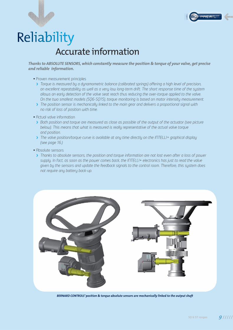
BERNARD CONTROLS’ position & torque absolute sensors are mechanically linked to the output shaft
Accurate information
• Proven measurement principles
Torque is measured by a dynamometric balance (calibrated springs) offering a high level of precision,
an excellent repeatability as well as a very low long-term drift. The short response time of the system
allows an early detection of the valve seat reach thus reducing the over-torque applied to the valve.
On the two smallest models (SQ6-SQ15), torque monitoring is based on motor intensity measurement.
The position sensor is mechanically linked to the main gear and delivers a proportional signal with
no risk of loss of position with time.
• Actual valve information
Both position and torque are measured as close as possible of the output of the actuator (see picture
below). This means that what is measured is really representative of the actual valve torque
and position.
The valve position/torque curve is available at any time directly on the INTELLI+ graphical display
(see page 16.)
• Absolute sensors
Thanks to absolute sensors, the position and torque information are not lost even after a loss of power
supply. In fact, as soon as the power comes back, the INTELLI+ electronics has just to read the value
given by the sensors and update the feedback signals to the control room. Therefore, this system does
not require any battery back-up.
Thanks to ABSOLUTE SENSORS, which constantly measure the position & torque of your valve, get precise and reliable information.
SQ & ST ranges 9
LAB
EL
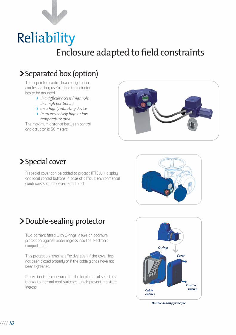
The separated control box confi guration
can be specially useful when the actuator
has to be mounted:
in a diffi cult access (manhole, in a high position,...)
on a highly vibrating device in an excessively high or low
temperature area The maximum distance between control
and actuator is 50 meters.
Separated box (option)
A special cover can be added to protect INTELLI+ display
and local control buttons in case of diffi cult environmental
conditions such as desert sand blast.
Two barriers fi tted with O-rings insure an optimum
protection against water ingress into the electronic
compartment.
This protection remains effective even if the cover has
not been closed properly or if the cable glands have not
been tightened.
Protection is also ensured for the local control selectors
thanks to internal reed switches which prevent moisture
ingress.
Special cover
Double-sealing protector
O-rings
Cover
Cable entries
Captive screws
Double-sealing principle
Enclosure adapted to fi eld constraints
10
SQ & ST ranges 11
LAB
EL
Display indicationsValve position in % of opening valve torque can also be displayed in % of actuator maximum torque.
Local controls inhibited by the remote controller.
Emergency shutdown signal received.
Infrared link is detected.
This icon is displayed in case of alarm.
In the case of signalling option (only for subsidiaries functions), this icon is blinking if the battery voltage
is getting low.
When a positioner is built-in, the set point value is displayed in percentage. This indication is blinking
in case of loss of control signal.
This icon indicates that the fi eldbus board is installed. The square displays the status
of the communication: no communication, communication in progress or faulty module.
In case of redundant fi eldbus interface, two squares are displayed. The squares display the status
of each communication line: no communication, a channel is acting as primary or backup, communication
in progress or a faulty module.
0%
BUS
1 2
5% OpenTorque 20%
ESD
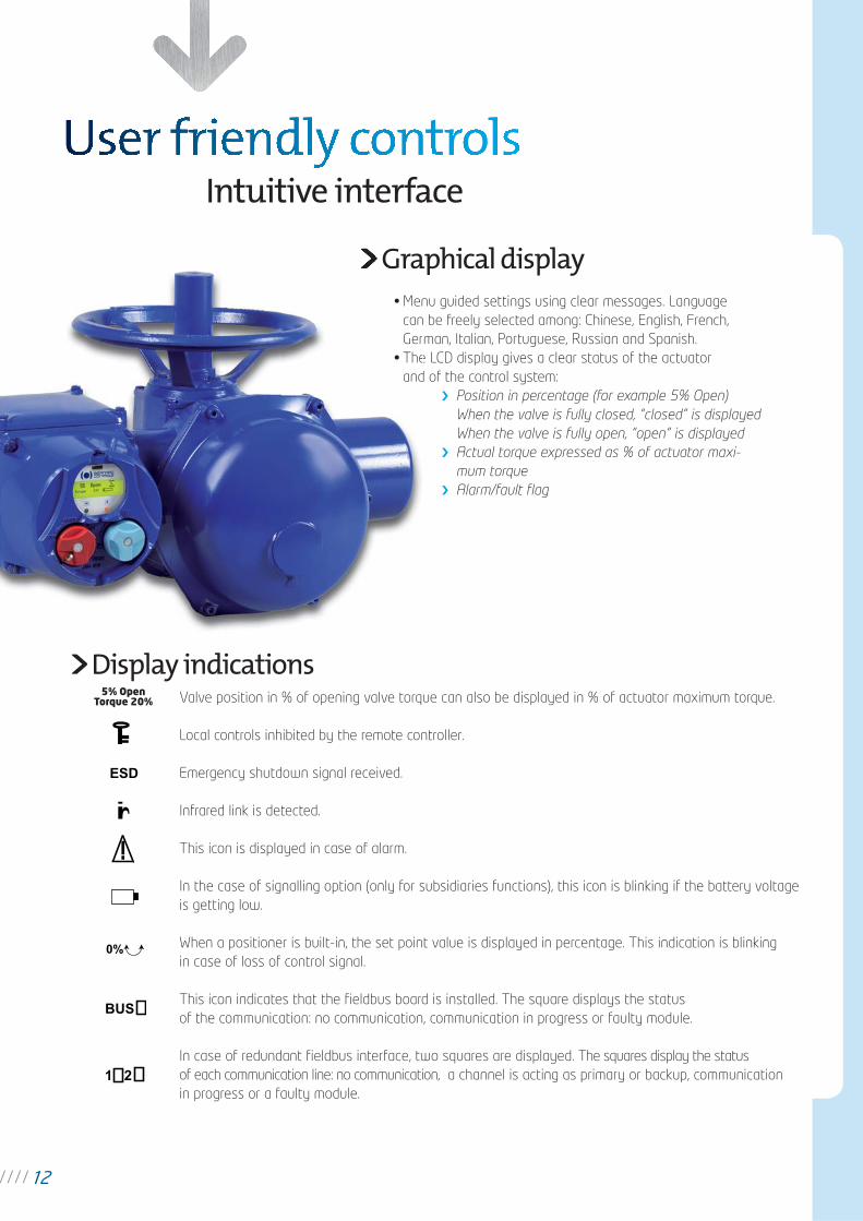
• Menu guided settings using clear messages. Language
can be freely selected among: Chinese, English, French,
German, Italian, Portuguese, Russian and Spanish.
• The LCD display gives a clear status of the actuator
and of the control system:
Position in percentage (for example 5% Open)
When the valve is fully closed, “closed” is displayed
When the valve is fully open, “open” is displayed
Actual torque expressed as % of actuator maxi-
mum torque
Alarm/fault fl ag
Graphical displaynu
n b
m
e L
d o
Grap• Men
can
Ger
• The
and
Intuitive interface
12
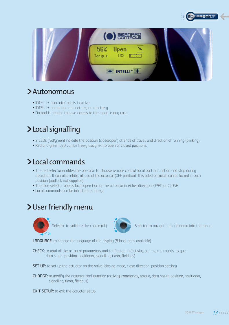
• INTELLI+ user interface is intuitive.
• INTELLI+ operation does not rely on a battery.
• No tool is needed to have access to the menu in any case.
• 2 LEDs (red/green) indicate the position (close/open) at ends of travel, and direction of running (blinking).
• Red and green LED can be freely assigned to open or closed positions.
• The red selector enables the operator to choose remote control, local control function and stop during
operation. It can also inhibit all use of the actuator (OFF position). This selector switch can be locked in each
position (padlock not supplied).
• The blue selector allows local operation of the actuator in either direction: OPEN or CLOSE.
• Local commands can be inhibited remotely.
Autonomous
Local signalling
Local commands
LANGUAGE: to change the language of the display (8 languages available)
CHECK: to read all the actuator parameters and confi guration (activity, alarms, commands, torque,
data sheet, position, positioner, signalling, timer, fi eldbus)
SET UP: to set up the actuator on the valve (closing mode, close direction, position setting)
CHANGE: to modify the actuator confi guration (activity, commands, torque, data sheet, position, positioner,
signalling, timer, fi eldbus)
EXIT SETUP: to exit the actuator setup
User friendly menu
Selector to validate the choice (ok) Selector to navigate up and down into the menu
OK
SQ & ST ranges 13
LAB
EL
During the actuator on valve setting procedure, the user is guided step by step by INTELLI+:
Choice of closing (on torque or on position),
Choice of direction to close,
Drive the actuator to the closed and the open position and validate the position.
For certain valves, as an example gate valves equipped with back seat, INTELLI+ can automatically perform
this setting: the actuator detects the extreme positions (using the torque limiter), tests the inertia in order
to optimize this setting.
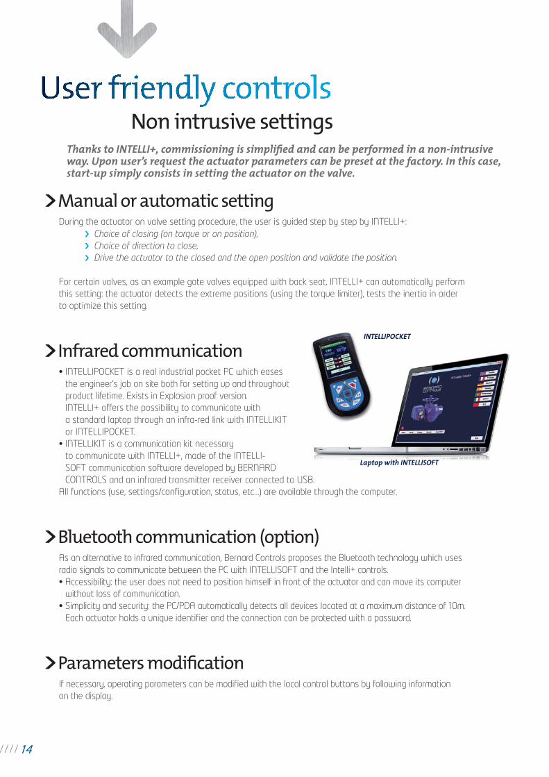
• INTELLIPOCKET is a real industrial pocket PC which eases
the engineer’s job on site both for setting up and throughout
product lifetime. Exists in Explosion proof version.
INTELLI+ offers the possibility to communicate with
a standard laptop through an infra-red link with INTELLIKIT
or INTELLIPOCKET.
• INTELLIKIT is a communication kit necessary
to communicate with INTELLI+, made of the INTELLI-
SOFT communication software developed by BERNARD
CONTROLS and an infrared transmitter receiver connected to USB.
All functions (use, settings/confi guration, status, etc…) are available through the computer.
If necessary, operating parameters can be modifi ed with the local control buttons by following information
on the display.
As an alternative to infrared communication, Bernard Controls proposes the Bluetooth technology which uses
radio signals to communicate between the PC with INTELLISOFT and the Intelli+ controls.
• Accessibility: the user does not need to position himself in front of the actuator and can move its computer
without loss of communication.
• Simplicity and security: the PC/PDA automatically detects all devices located at a maximum distance of 10m.
Each actuator holds a unique identifi er and the connection can be protected with a password.
Thanks to INTELLI+, commissioning is simplifi ed and can be performed in a non-intrusive way. Upon user’s request the actuator parameters can be preset at the factory. In this case, start-up simply consists in setting the actuator on the valve.
Non intrusive settings
Manual or automatic setting
Infrared communication
Parameters modifi cation
Bluetooth communication (option)
INTELLIPOCKET
Laptop with INTELLISOFT
14
SQ & ST ranges 15
LAB
EL
Thanks to its absolute sensors and its microprocessor technology, INTELLI+ continuously monitors its components as well as the actuator status and measures some important valve parameters.INTELLI+ provides users with a great deal of information to help with system diagnosis and aid in scheduling their valves preventative maintenance. INTELLI+ helps maximise process availability by reducing maintenance downtime.
Preventative maintenance
Parameters are available on the display through the menu to check the activity of the actuator:
Number of starts: total starts since the actuator manufacturing
A partial counter can be selected
Running time: total running time since the actuator manufacturing
Starts last 12h: number of starts in the last 12 hours (to check the modulating activity i.e.)
Handwheel action: indicates if the handwheel was operated by manual operation since
the last electrical command
INTELLI+ stores in its memory the data sheet of the actuator: customer tag number, BERNARD CONTROLS
serial number, duty rating, classifi cation level, manufacturing date, etc.
INTELLI+ checks the operation of its components, particularly torque sensor, position sensor, microprocessor
and EEPROM memory.
INTELLI+ constantly monitors its performance in order to detect any problem of over-travel, jammed motor,
rotation direction, lost phase, motor thermal overload and many others.
Refer to Confi guration page 35 for a complete list of alarms.
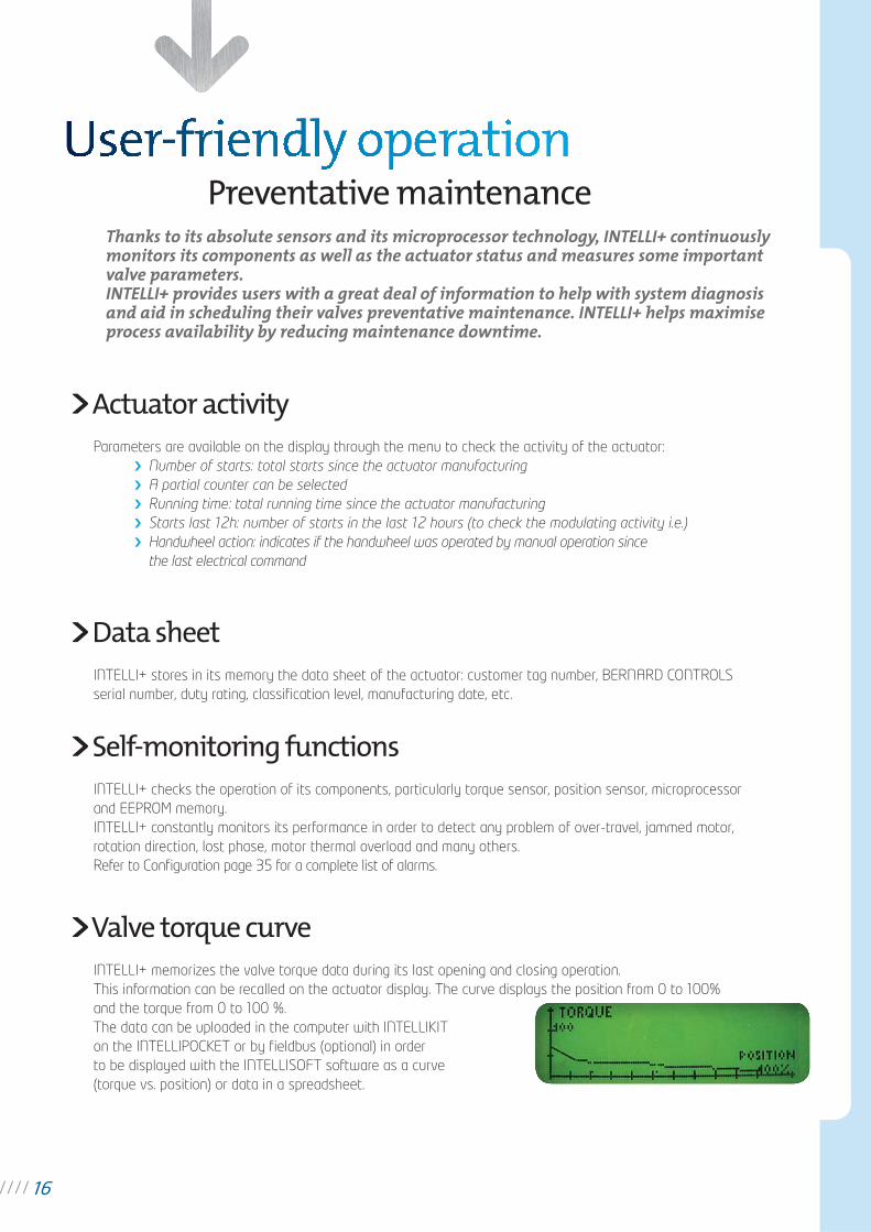
INTELLI+ memorizes the valve torque data during its last opening and closing operation.
This information can be recalled on the actuator display. The curve displays the position from 0 to 100%
and the torque from 0 to 100 %.
The data can be uploaded in the computer with INTELLIKIT
on the INTELLIPOCKET or by fi eldbus (optional) in order
to be displayed with the INTELLISOFT software as a curve
(torque vs. position) or data in a spreadsheet.
Actuator activity
Data sheet
Self-monitoring functions
Valve torque curve
16
Easy on-site management
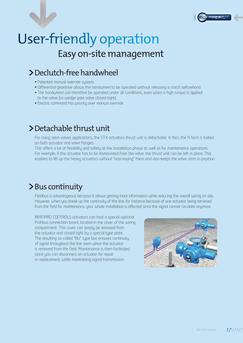
Fieldbus is advantageous because it allows getting more information while reducing the overall wiring on site.
However, when you break up the continuity of the line, for instance because of one actuator being retrieved
from the fi eld for maintenance, your whole installation is affected since the signal cannot circulate anymore.
BERNARD CONTROLS actuators can host a special optional
Profi bus connection board, located in the cover of the wiring
compartment. This cover can simply be removed from
the actuator and closed tight by a special type plate.
The resulting so-called “BU” type box ensures continuity
of signal throughout the line even when the actuator
is removed from the fi eld. Maintenance is then facilitated
since you can disconnect an actuator for repair
or replacement, while maintaining signal transmission.
• Patented manual override system.
• Differential geardrive allows the handwheel to be operated without releasing a clutch beforehand.
• The handwheel can therefore be operated under all conditions, even when a high torque is applied
to the valve (i.e wedge gate valve closed tight).
• Electric command has priority over manual override.
For rising stem valves applications, the STX actuators thrust unit is detachable. In fact, the A form is bolted
on both actuator and valve fl anges.
This offers a lot of fl exibility and safety at the installation phase as well as for maintenance operations.
For example, if the actuator has to be dismounted from the valve, the thrust unit can be left in place. This
enables to lift up the heavy actuators without “unscrewing” them and also keeps the valve stem in position.
Declutch-free handwheel
Detachable thrust unit
Bus continuity
SQ & ST ranges 17
LAB
EL
Plant installations protection
Partial stroking is a key specifi cation of BERNARD CONTROLS actuators which enable to check
the availability of the connected MOVs.
This test consists in the execution of a very short return travel.
Starting position as well as partial stroke amplitude are programmable.
This command can be either hardwired or sent by fi eldbus. A warning is generated in event of problems
occuring during this test.
A password can be entered to protect access to parameters modifi cation and actuator on valve setting.
INTELLI+ continuously monitors the actuator performances. Up to 17 different types of faults and alarms can
be reported (refer to Confi guration on page 35 for a complete list of alarms).
An exclamation mark in a triangle on the local display indicates an alarm.
The actuator can still operate normally in case of an alarm, for example there is an alarm after ‘Too many
starts’. The alarm will automatically reset when the fault no longer exists.
ESD (Emergency Shut Down) is a remote emergency control signal with priority over all other commands.
Depending upon the valve operation, ESD can be confi gured as an Open, Close or Stop command.
To increase the availability of the actuator in extreme conditions, ESD can be set to ignore a torque overload
condition.
This function enables an increase in the operating time of the actuator, i.e. to avoid water-hammer effect
in a pipe.
Travel time can be programmed independently in both opening and closing directions.
It is also possible to apply the timer function to a limited section of the stroke.
Partial stroking
Protection by password
Alarms indication
Emergency shutdown (ESD)
Timer
18
INTELLI+ includes an automatic phase correction device. In case of 3 phase power supply, whatever
the power connection, the actuator always rotates in the correct direction. If one of the phases
is not present, the actuator stops automatically and the fault relay drops.
An automatic delay protects the actuator and valve from all rapid rotational direction changes while limiting
the effects of the mechanical pieces in inertia.
The actuator is totally autonomous and does not require a battery to operate. However, a signalling battery
back-up optional board can be added for signalling purpose only.
This battery is activated in case of loss of power supply and allows:
to use the INTELLI+ display.
to update remote signalling (valve position, alarms, ...)
to refresh fi eldbus information
Low battery condition is automatically detected by the INTELLI+ and a warning message is sent.
A low battery condition does not have any consequence on actuator operation.
Note: a 24VDC external power supply input is also present on the INTELLI+ board to achieve the same
functionality and more.
One changeover (SPDT) relay indicates that the actuator is unavailable. This fault monitoring relay reports
5 types of defaults as a standard. Additional defaults to be reported can be easily added by the user (see
Confi guration on page 34). The monitoring relay is always energized and drops out only in event of a fault.
Motorised valve protection
Phase monitoring
Protection of change in direction
Signalling continuity (option)
Fault monitoring relay
SQ & ST ranges 19
LAB
EL
INTELLI+ can be equipped with an analogue position and torque feedback board.
This module delivers a 0/4-20mA signal proportional to the percentage of the valve opening. A voltage
signal (i.e. 0-10V) can also be obtained by connecting an external resistance. The board can be either
supplied by an external (12 to 32 VDC) source of power or internally, by the INTELLI+ electronics.
This module also delivers a 4 - 20mA signal propotional to the real torque of the valve.
A positioner board can be installed into the INTELLI+ to allow the operator to drive the valve to intermediate
positions (Class III modulating).
The positioner module has been designed to work with either current (i.e. 4-20mA) or voltage (i.e. 0-10V)
analogue signals
One input signal: the set-point
One output signal: the actual valve position feedback
The input and output signals are fully isolated from each other. The setting procedure is fully automatic
and is performed in a non-intrusive way. The dead band can be adjusted by the user.
Remote indication is done through 4 relays, with the possibility of 23 available information.
Voltage free relays maintain their positions without battery backup. Normally open or normally closed contact
can be chosen. An optional board with 3 single option relays allows reporting of 3 additional indications.
Remote control can be achieved using a 10 to 250 V external voltage supply or by dry contacts, which uses
the actuators internal 24 VDC voltage supply.
This control can be confi gured as a pulse or self-holding remote command. Inputs on the board are completely
isolated by opto-isolators. It is also possible to control the actuator with a unique external contact, using one
of the two functions «Priority to open» or «Priority to close».
Position and torque transmitter
Positioner
Remote indications
Wire by wire command
Hardwired controls
20
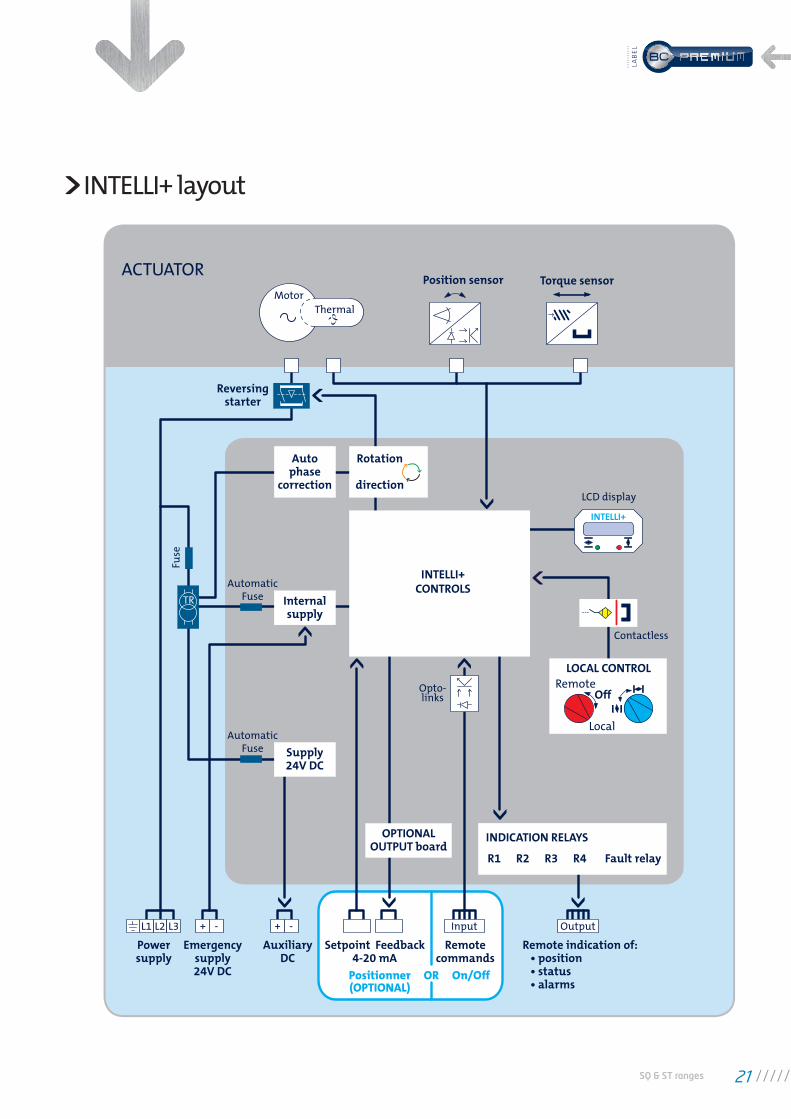
Position sensor
Reversingstarter
Autophase
correction
Internalsupply
Supply24V DC
OPTIONALOUTPUT board
LOCAL CONTROLRemote
Local
INDICATION RELAYS
R1 R2 R3 R4 Fault relay
Off
Rotation
direction
INTELLI+CONTROLS
Torque sensor
LCD display
INTELLI+
Motor
ACTUATOR
Thermal
Fuse
TR
AutomaticFuse
AutomaticFuse
Opto-links
Contactless
Powersupply
Emergencysupply24V DC
AuxiliaryDC
Remotecommands
Remote indication of:
Input+L1 L2 L3 - + -
Setpoint
Positionner OR On/Off(OPTIONAL)
Feedback4-20 mA
Output
INTELLI+ layout
SQ & ST ranges 21
LAB
EL
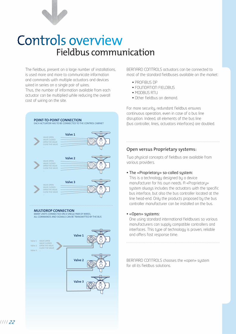
The fi eldbus, present on a large number of installations,
is used more and more to communicate information
and commands with multiple actuators and devices
wired in series on a single pair of wires.
Thus, the number of information available from each
actuator can be multiplied while reducing the overall
cost of wiring on the site.
BERNARD CONTROLS actuators can be connected to
most of the standard fi eldbuses available on the market:
• PROFIBUS DP
• FOUNDATION FIELDBUS
• MODBUS RTU
• Other fi eldbus on demand.
For more security, redundant fi eldbus ensures
continuous operation, even in case of a bus line
disruption. Indeed, all elements of the bus line
(bus controller, lines, actuators interfaces) are doubled.
Open versus Proprietary systems:
Two physical concepts of fi eldbus are available from
various providers.
• The «Proprietary» so-called system:This is a technology designed by a device
manufacturer for his own needs. A «Proprietary»
system always includes the actuators with the specifi c
bus interface, but also the bus controller located at the
line head-end. Only the products proposed by the bus
controller manufacturer can be installed on the bus.
• «Open» systems: One using standard international fi eldbuses so various
manufacturers can supply compatible controllers and
interfaces. This type of technology is proven, reliable
and offers fast response time.
BERNARD CONTROLS chooses the «open» system
for all its fi eldbus solutions.
Fieldbus communication
22
POINT-TO-POINT CONNECTIONEACH ACTUATOR HAS TO BE CONNECTED TO THE CONTROL CABINET
MULTIDROP CONNECTIONMANY UNITS CONNECTED ON A SINGLE PAIR OF WIRES;ALL COMMANDS AND SIGNALS CAN BE TRANSMITTED BY THE BUS
Valve 1
Valve 2
Valve 3
Valve 1
Valve 2
Valve 3
VALVE OPENVALVE CLOSEDOPEN THE VALVECLOSE THE VALVE...
VALVE OPENVALVE CLOSEDOPEN THE VALVECLOSE THE VALVE...
VALVE OPENVALVE CLOSEDOPEN THE VALVECLOSE THE VALVE...
Valve 1
Valve 2
Valve 3
VALVE OPENVALVE CLOSEDOPEN THE VALVECLOSE THE VALVE...
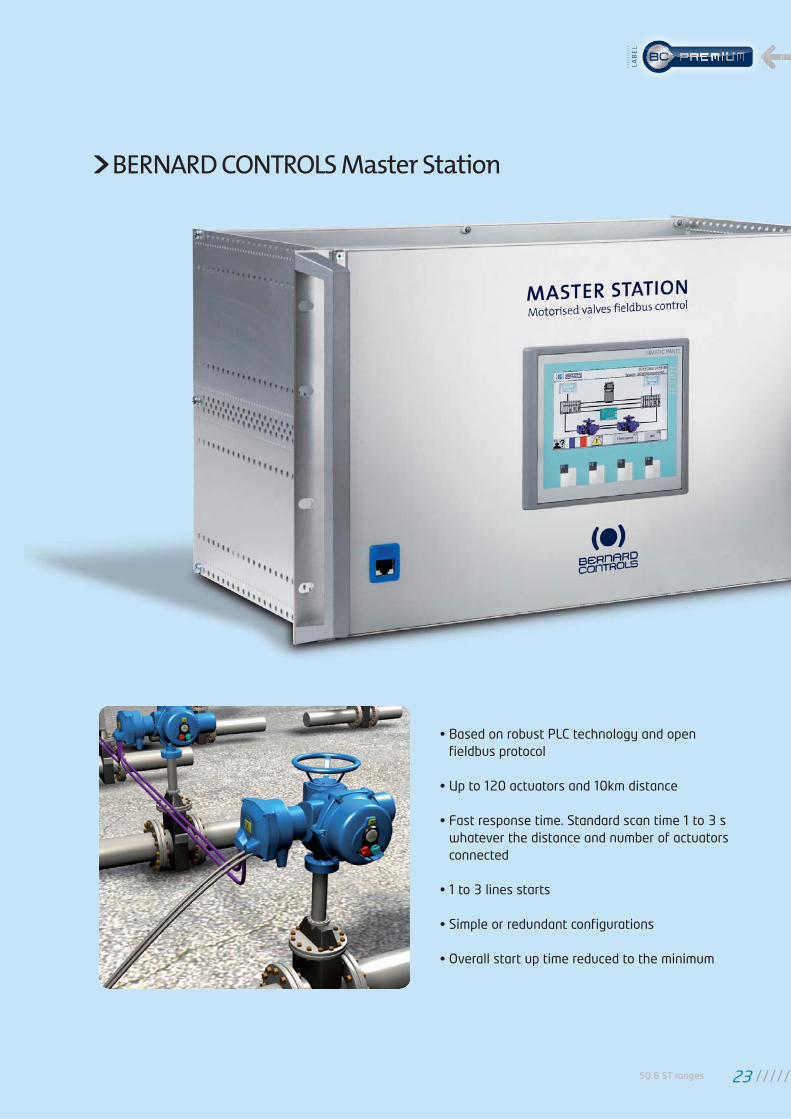
• Based on robust PLC technology and open fi eldbus protocol
• Up to 120 actuators and 10km distance
• Fast response time. Standard scan time 1 to 3 s whatever the distance and number of actuators connected
• 1 to 3 lines starts
• Simple or redundant confi gurations
• Overall start up time reduced to the minimum
BERNARD CONTROLS Master Station
SQ & ST ranges 23
LAB
EL
GE
NE
RA
L
SP
EC
IFIC
AT
ION
S
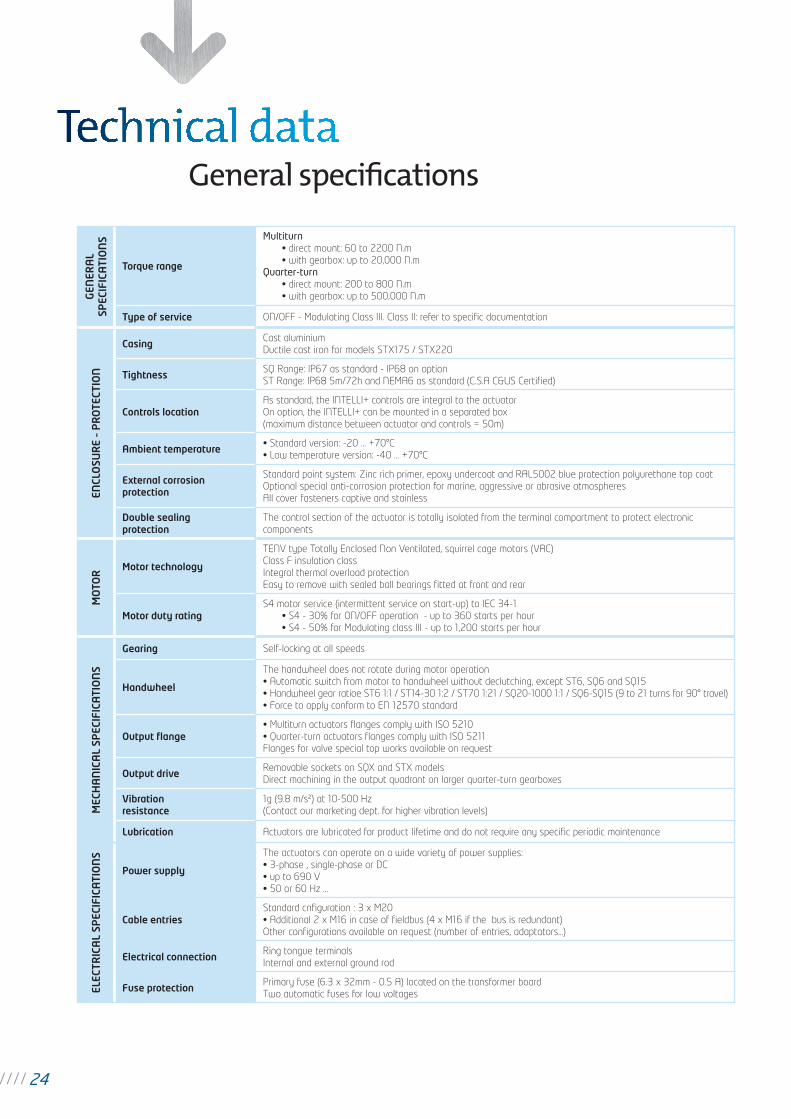
Torque range
Multiturn
• direct mount: 60 to 2200 N.m
• with gearbox: up to 20,000 N.m
Quarter-turn • direct mount: 200 to 800 N.m
• with gearbox: up to 500,000 N.m
Type of service ON/OFF - Modulating Class III. Class II: refer to specifi c documentation
EN
CLO
SU
RE
– P
RO
TE
CT
ION
CasingCast aluminium
Ductile cast iron for models STX175 / STX220
TightnessSQ Range: IP67 as standard - IP68 on option
ST Range: IP68 5m/72h and NEMA6 as standard (C.S.A C&US Certifi ed)
Controls location
As standard, the INTELLI+ controls are integral to the actuator
On option, the INTELLI+ can be mounted in a separated box
(maximum distance between actuator and controls = 50m)
Ambient temperature• Standard version: -20 … +70°C
• Low temperature version: -40 … +70°C
External corrosion
protection
Standard paint system: Zinc rich primer, epoxy undercoat and RAL5002 blue protection polyurethane top coat
Optional special anti-corrosion protection for marine, aggressive or abrasive atmospheres
All cover fasteners captive and stainless
Double sealing
protection
The control section of the actuator is totally isolated from the terminal compartment to protect electronic
components
MO
TO
R
Motor technology
TENV type Totally Enclosed Non Ventilated, squirrel cage motors (VAC)
Class F insulation class
Integral thermal overload protection
Easy to remove with sealed ball bearings fi tted at front and rear
Motor duty rating
S4 motor service (intermittent service on start-up) to IEC 34-1
• S4 - 30% for ON/OFF operation - up to 360 starts per hour
• S4 - 50% for Modulating class III - up to 1,200 starts per hour
ME
CH
AN
ICA
L S
PE
CIF
ICA
TIO
NS
Gearing Self-locking at all speeds
Handwheel
The handwheel does not rotate during motor operation
• Automatic switch from motor to handwheel without declutching, except ST6, SQ6 and SQ15
• Handwheel gear ratioe ST6 1:1 / ST14-30 1:2 / ST70 1:21 / SQ20-1000 1:1 / SQ6-SQ15 (9 to 21 turns for 90° travel)
• Force to apply conform to EN 12570 standard
Output fl ange
• Multiturn actuators fl anges comply with ISO 5210
• Quarter-turn actuators fl anges comply with ISO 5211
Flanges for valve special top works available on request
Output driveRemovable sockets on SQX and STX models
Direct machining in the output quadrant on larger quarter-turn gearboxes
Vibration
resistance
1g (9.8 m/s²) at 10-500 Hz
(Contact our marketing dept. for higher vibration levels)
Lubrication Actuators are lubricated for product lifetime and do not require any specifi c periodic maintenance
ELE
CT
RIC
AL
SP
EC
IFIC
AT
ION
S
Power supply
The actuators can operate on a wide variety of power supplies:
• 3-phase , single-phase or DC
• up to 690 V
• 50 or 60 Hz …
Cable entries
Standard cnfi guration : 3 x M20
• Additional 2 x M16 in case of fi eldbus (4 x M16 if the bus is redundant)
Other confi gurations available on request (number of entries, adaptators...)
Electrical connectionRing tongue terminals
Internal and external ground rod
Fuse protectionPrimary fuse (6.3 x 32mm - 0.5 A) located on the transformer board
Two automatic fuses for low voltages
General specifi cations
24
PO
SIT
ION
AN
D
TO
RQ
UE
SE
NS
OR
S
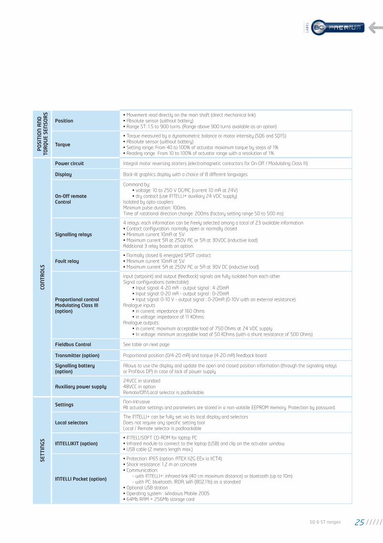
Position
• Movement read directly on the main shaft (direct mechanical link)
• Absolute sensor (without battery)
• Range ST: 1.5 to 900 turns. (Range above 900 turns available as an option)
Torque
• Torque measured by a dynamometric balance or motor intensity (SQ6 and SQ15)
• Absolute sensor (without battery)
• Setting range: From 40 to 100% of actuator maximum torque by steps of 1%
• Reading range From 10 to 100% of actuator range with a resolution of 1%
CO
NT
RO
LS
Power circuit Integral motor reversing starters (electromagnetic contactors for On-Off / Modulating Class III)
Display Back-lit graphics display with a choice of 8 different languages
On-Off remote
Control
Command by:
• voltage: 10 to 250 V DC/AC (current 10 mA at 24V)
• dry contact (use INTELLI+ auxiliary 24 VDC supply)
Isolated by opto-couplers
Minimum pulse duration: 100ms
Time of rotational direction change: 200ms (factory setting range 50 to 500 ms)
Signalling relays
4 relays: each information can be freely selected among a total of 23 available information
• Contact confi guration: normally open or normally closed
• Minimum current 10mA at 5V
• Maximum current 5A at 250V AC or 5A at 30VDC (inductive load)
Additional 3 relay boards on option.
Fault relay
• Normally closed & energized SPDT contact
• Minimum current 10mA at 5V
• Maximum current 5A at 250V AC or 5A at 30V DC (inductive load)
Proportional control
Modulating Class III
(option)
Input (setpoint) and output (feedback) signals are fully isolated from each other
Signal confi gurations (selectable):
• Input signal: 4-20 mA - output signal : 4-20mA
• Input signal: 0-20 mA - output signal : 0-20mA
• Input signal: 0-10 V - output signal : 0-20mA (0-10V with an external resistance)
Analogue inputs
• in current: impedance of 160 Ohms
• in voltage: impedance of 11 KOhms
Analogue outputs:
• in current: maximum acceptable load of 750 Ohms at 24 VDC supply
• In voltage: minimum acceptable load of 50 KOhms (with a shunt resistance of 500 Ohms)
Fieldbus Control See table on next page
Transmitter (option) Proportional position (0/4-20 mA) and torque (4-20 mA) feedback board
Signalling battery
(option)
Allows to use the display and update the open and closed position information (through the signaling relays
or Profi bus DP) in case of lack of power supply
Auxiliary power supply
24VCC in standard
48VCC in option
Remote/Off/Local selector is padlockable
SE
TT
ING
S
SettingsNon-Intrusive
All actuator settings and parameters are stored in a non-volatile EEPROM memory. Protection by password.
Local selectors
The INTELLI+ can be fully set via its local display and selectors
Does not require any specifi c setting tool
Local / Remote selector is padloackable
INTELLIKIT (option)
• INTELLISOFT CD-ROM for laptop PC
• Infrared module to connect to the laptop (USB) and clip on the actuator window
• USB cable (2 meters length max.)
INTELLI Pocket (option)
• Protection: IP65 (option: ATEX II2G EEx ia IICT4)
• Shock resistance: 1.2 m on concrete
• Communication:
- with INTELLI+: infrared link (40 cm maximum distance) or bluetooth (up to 10m)
- with PC: bluetooth, IRDA, Wifi (802.11b) as a standard
• Optional USB station
• Operating system : Windows Mobile 2005
• 64Mb RAM + 256Mb storage card
SQ & ST ranges 25
LAB
EL
For further information on electrical data, dimensions and wirings, please consult our Technical Handbooks
CO
NF
OR
MIT
Y T
O
EC
DIR
EC
TIV
ES
EC Directives
The actuators comply with:
• The 2004/108/EC electromagnetic compatibility
• The 2006/95/EC C Low Voltage
• The following harmonized standards:
- Generic emission standard-Industrial environment EN 61000-6-4
- Generic immunity standard - Industrial environment EN 61000-6-2
- Rotating electrical machines EN 60034-1
- Degrees of protection provided by enclosures (IP code) EN 60529
FIE
LD
BU
S C
ON
TR
OL
S
Profi bus DPV1
(option)
• PROFIBUS-DPV1 - RS 485
• Baud rate: 9.6 kbit/s up to 1.5 Mbit/s (autodetection)
• Communication protocol: PROFIBUS DPV1 slave-cyclic and acyclic
• Type of connection: single line (standard) or redundant line (option)
• Cable specifi cation: Profi bus certifi ed cable only
• Line connection without repeater:
- Actuators per line: 31 max.
- Line length: 1.2 km max. (0.75 mi)
• Line connection with repeaters:
- Number of repeaters per line: 9 max
- 30 actuators and 1 Km max. per segment
- Number of actuators per line with repeater: 124 maximum
- Line length with 9 repeaters: 10.2 km max. (6.2 mi)
• Scan speed (30 units & 1.2 km): 0.1s (at a baud rate of 93.75 Kbit/s)
• Power supply: internal and isolated via INTELLI+. Optional signalling battery or 24VDC external backup supply
update the open and closed position information in case of loss of power supply
• Technical approval: operability approved by PNO (Profi bus Nutzer Organisation)
Modbus
(option)
• MODBUS RTU - RS 485
• Transmission medium: 1 shielded pair cable
• Functions: Half Duplex, asynchronous mode, multidrop
• Baud rate: 1.2k to 115 Kbit/s
• Format: 8 data bits, 1 stop bit, no parity
• Communication protocol: Modbus (slave)
• Modbus address: confi gurable by the actuator menu
Foundation Fieldbus
(option)
• H1 speed = 31.25kBit/s
• Fully compliant with fi eldbus standard IEC 61158
• Physical layer: IEC 61158-2, 2 wires communication
• Current consumption: 20mA
• Operating voltage: 9 to 32 VDC
• Cable specifi cation: Type A (for example: 3076F Belden)
• Line connection
- Actuators per line without repeater: 31 max.
- Line length without repeater: 1.9 km max. (1.2 mi)
- Number of repeaters per line: 4 max.
- Maximum number of actuators and line length depends on consumption available
• Technical approval: Foundation tested. Several DCS manufacturer operability checked.
26
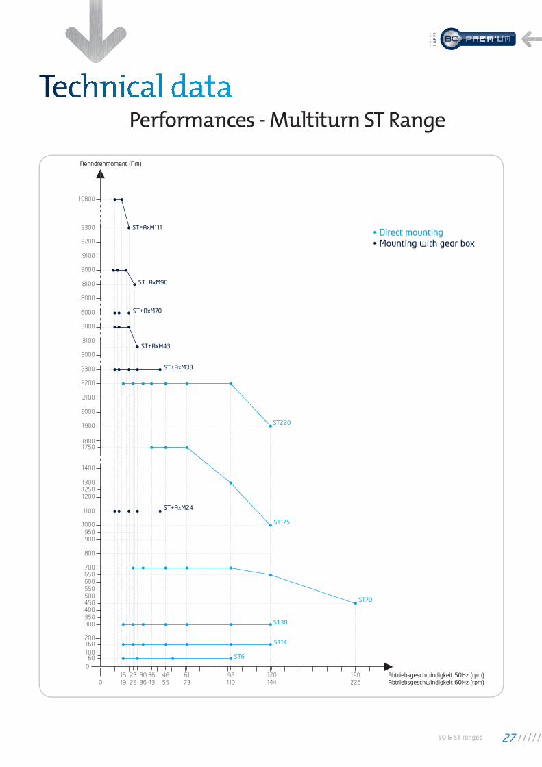
Performances - Multiturn ST Range
0
200160
60100
700
800
900
1000
950
1300
12001250
1100
1400
1900
2000
2100
2200
2300
3000
3100
3800
6000
8000
8100
9000
10800
9100
9200
9300
Nenndrehmoment (Nm)
0
600650
500550
450400350300
18001750
16
19
23
28
30
36
36
43
46
55
61
73
92
110
120
144
190
226Abtriebsgeschwindigkeit 50Hz (rpm) Abtriebsgeschwindigkeit 60Hz (rpm)
ST14
ST30
ST70
ST175
ST+AxM24
ST+AxM33
ST+AxM43
ST+AxM70
ST+AxM90
ST+AxM111
ST220
ST6
• Direct mounting• Mounting with gear box
SQ & ST ranges 27
LAB
EL
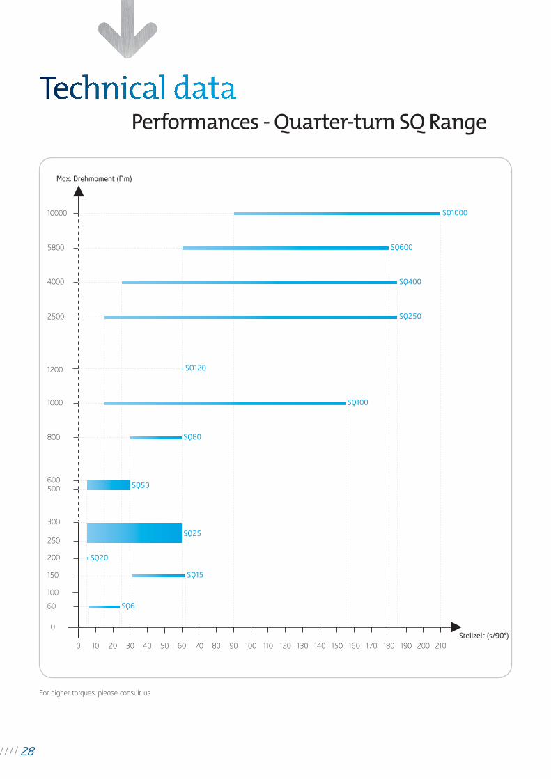
Performances - Quarter-turn SQ Range
For higher torques, please consult us
0
500
800
1000
1200
2500
4000
5800
10000
Max. Drehmoment (Nm)
0 10 20 30 40 50 60 70 80 90 100 110 120 130 140 150 160 170 180 190
60
100
150
200
250
Stellzeit (s/90°)200 210
300
600
SQ6
SQ20
SQ15
SQ120
SQ25
SQ50
SQ80
SQ100
SQ250
SQ400
SQ600
SQ1000
28
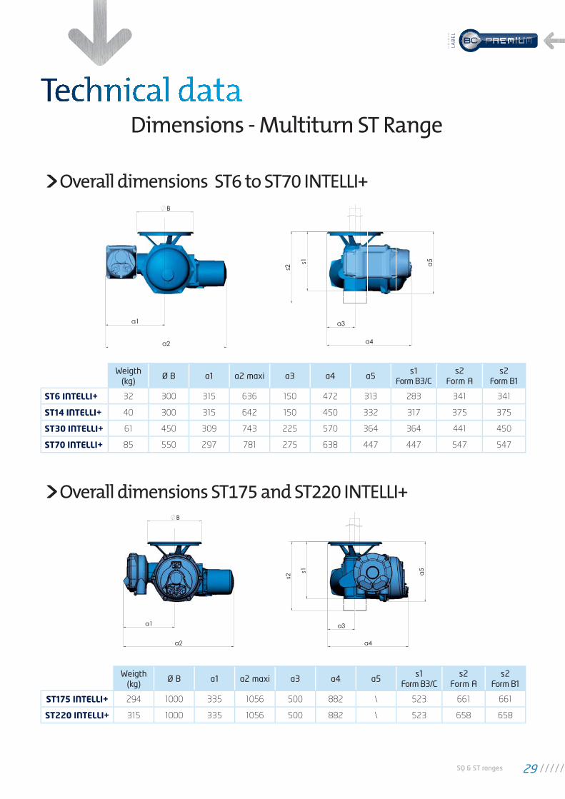
Dimensions - Multiturn ST Range
Overall dimensions ST6 to ST70 INTELLI+
Overall dimensions ST175 and ST220 INTELLI+
Weigth (kg)
Ø B a1 a2 maxi a3 a4 a5s1
Form B3/Cs2
Form As2
Form B1
ST6 INTELLI+ 32 300 315 636 150 472 313 283 341 341
ST14 INTELLI+ 40 300 315 642 150 450 332 317 375 375
ST30 INTELLI+ 61 450 309 743 225 570 364 364 441 450
ST70 INTELLI+ 85 550 297 781 275 638 447 447 547 547
Weigth (kg)
Ø B a1 a2 maxi a3 a4 a5s1
Form B3/Cs2
Form As2
Form B1
ST175 INTELLI+ 294 1000 335 1056 500 882 \ 523 661 661
ST220 INTELLI+ 315 1000 335 1056 500 882 \ 523 658 658
SQ & ST ranges 29
LAB
EL
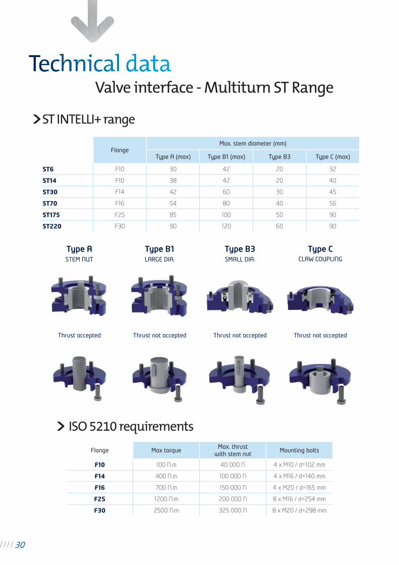
Valve interface - Multiturn ST Range
FlangeMax. stem diameter (mm)
Type A (max) Type B1 (max) Type B3 Type C (max)
ST6 F10 30 42 20 32
ST14 F10 38 42 20 40
ST30 F14 42 60 30 45
ST70 F16 54 80 40 56
ST175 F25 85 100 50 90
ST220 F30 90 120 60 90
Flange Max torqueMax. thrust
with stem nutMounting bolts
F10 100 N.m 40 000 N 4 x M10 / d=102 mm
F14 400 N.m 100 000 N 4 x M16 / d=140 mm
F16 700 N.m 150 000 N 4 x M20 / d=165 mm
F25 1200 N.m 200 000 N 8 x M16 / d=254 mm
F30 2500 N.m 325 000 N 8 x M20 / d=298 mm
ISO 5210 requirements
Type A
STEM NUT
Type B1
LARGE DIA.
Type B3
SMALL DIA.
Type CCLAW COUPLING
Thrust accepted Thrust not accepted Thrust not accepted Thrust not accepted
ST INTELLI+ range
30
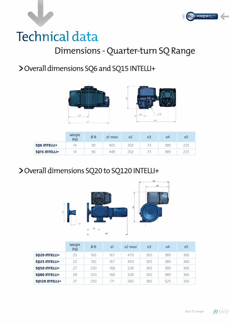
Dimensions - Quarter-turn SQ Range
Overall dimensions SQ6 and SQ15 INTELLI+
Overall dimensions SQ20 to SQ120 INTELLI+
Weight(kg)
Ø B a1 maxi a2 a3 a4 a5
SQ6 INTELLI+ 14 90 405 202 73 389 225
SQ15 INTELLI+ 14 90 448 202 73 389 225
Weight(kg)
Ø B a1 a2 maxi a3 a4 a5
SQ20 INTELLI+ 25 160 167 479 305 389 366
SQ25 INTELLI+ 22 160 167 459 305 389 366
SQ50 INTELLI+ 27 250 168 528 305 389 366
SQ80 INTELLI+ 28 250 168 528 305 389 366
SQ120 INTELLI+ 37 250 171 583 385 525 356
SQ & ST ranges 31
LAB
EL
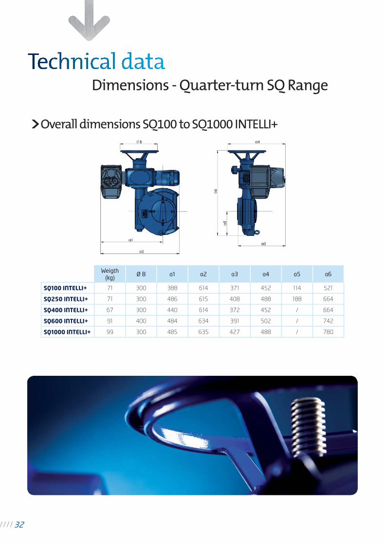
Dimensions - Quarter-turn SQ Range
Overall dimensions SQ100 to SQ1000 INTELLI+
Weigth(kg)
Ø B a1 a2 a3 a4 a5 a6
SQ100 INTELLI+ 71 300 388 614 371 452 114 521
SQ250 INTELLI+ 71 300 486 615 408 488 188 664
SQ400 INTELLI+ 67 300 440 614 372 452 / 664
SQ600 INTELLI+ 91 400 484 634 391 502 / 742
SQ1000 INTELLI+ 99 300 485 635 427 488 / 780
32
Com
biD
irect
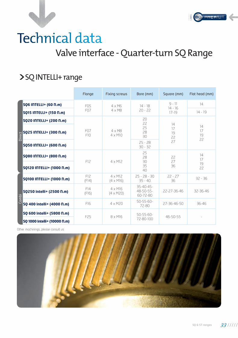
Valve interface - Quarter-turn SQ Range
SQ INTELLI+ range
Flange Fixing screws Bore (mm) Square (mm) Flat head (mm)
SQ6 INTELLI+ (60 N.m) F05
F07
4 x M6
4 x M8
14 - 18
20 - 22
9 - 11
14 - 16
17-19
14
SQ15 INTELLI+ (150 N.m) 14 - 19
SQ20 INTELLI+ (200 N.m)
F07
F10
4 x M8
4 x M10
20
22
25
28
30
14
17
19
22
27
14
17
19
22
SQ25 INTELLI+ (300 N.m)
SQ50 INTELLI+ (600 N.m)25 - 28
30 - 32
SQ80 INTELLI+ (800 N.m)F12 4 x M12
25
28
30
35
40
22
27
36
14
17
19
22SQ120 INTELLI+ (1000 N.m)
SQ100 INTELLI+ (1000 N.m)F12
(F14)
4 x M12
(4 x M16)
25 - 28 - 30
35 - 40
22 - 27
3632 - 36
SQ250 Intelli+ (2500 N.m)F14
(F16)
4 x M16
(4 x M20)
35-40-45-
48-50-55-
60-72-80
22-27-36-46 32-36-46
SQ 400 Intelli+ (4000 N.m) F16 4 x M2050-55-60-
72-8027-36-46-50 36-46
SQ 600 Intelli+ (5800 N.m)F25 8 x M16
50-55-60-
72-80-10046-50-55 -
SQ 1000 Intelli+ (10000 N.m)
Other machinings, please consult us
SQ & ST ranges 33
LAB
EL
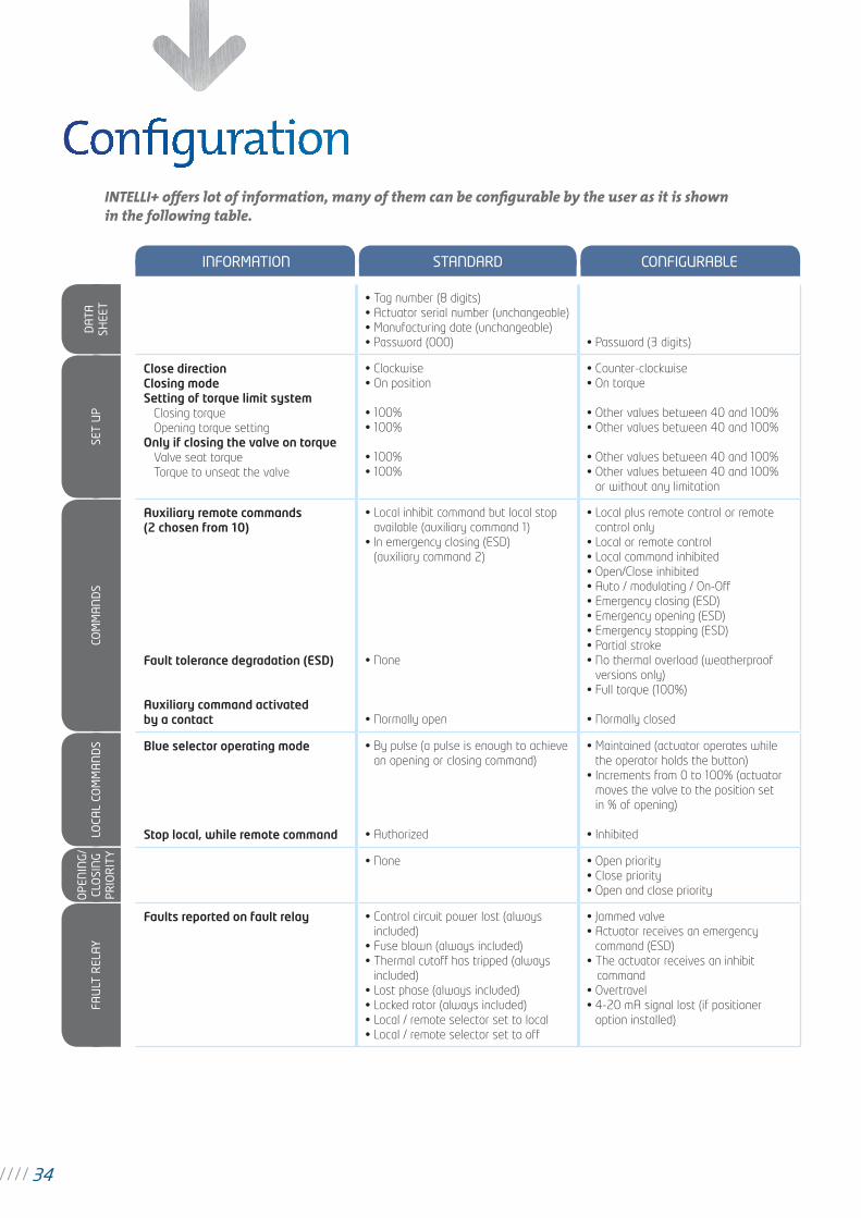
INTELLI+ offers lot of information, many of them can be confi gurable by the user as it is shown in the following table.
INFORMATION STANDARD CONFIGURABLE
• Tag number (8 digits)
• Actuator serial number (unchangeable)
• Manufacturing date (unchangeable)
• Password (000) • Password (3 digits)
Close direction
Closing mode
Setting of torque limit system
Closing torque
Opening torque setting
Only if closing the valve on torque
Valve seat torque
Torque to unseat the valve
• Clockwise
• On position
• 100%
• 100%
• 100%
• 100%
• Counter-clockwise
• On torque
• Other values between 40 and 100%
• Other values between 40 and 100%
• Other values between 40 and 100%
• Other values between 40 and 100%
or without any limitation
Auxiliary remote commands
(2 chosen from 10)
Fault tolerance degradation (ESD)
Auxiliary command activated
by a contact
• Local inhibit command but local stop
available (auxiliary command 1)
• ln emergency closing (ESD)
(auxiliary command 2)
• None
• Normally open
• Local plus remote control or remote
control only
• Local or remote control
• Local command inhibited
• Open/Close inhibited
• Auto / modulating / On-Off
• Emergency closing (ESD)
• Emergency opening (ESD)
• Emergency stopping (ESD)
• Partial stroke
• No thermal overload (weatherproof
versions only)
• Full torque (100%)
• Normally closed
Blue selector operating mode
Stop local, while remote command
• By pulse (a pulse is enough to achieve
an opening or closing command)
• Authorized
• Maintained (actuator operates while
the operator holds the button)
• Increments from 0 to 100% (actuator
moves the valve to the position set
in % of opening)
• Inhibited
• None • Open priority
• Close priority
• Open and close priority
Faults reported on fault relay • Control circuit power lost (always
included)
• Fuse blown (always included)
• Thermal cutoff has tripped (always
included)
• Lost phase (always included)
• Locked rotor (always included)
• Local / remote selector set to local
• Local / remote selector set to off
• Jammed valve
• Actuator receives an emergency
command (ESD)
• The actuator receives an inhibit
command
• Overtravel
• 4-20 mA signal lost (if positioner
option installed)
OPE
NIN
G/
CLO
SIN
G
PRIO
RIT
YLO
CAL
COM
MA
ND
SCO
MM
AN
DS
SET
UP
DA
TASH
EET
FAU
LT R
ELA
Y
34
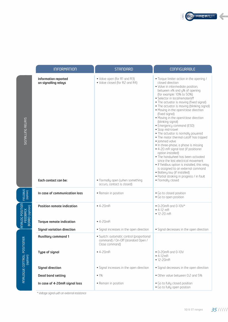
* Voltage signal with an external resistance
INFORMATION STANDARD CONFIGURABLE
Information reported
on signalling relays
Each contact can be:
• Valve open (for R1 and R3)
• Valve closed (for R2 and R4)
• Normally open (when something
occurs, contact is closed)
• Torque limiter action in the opening /
closed direction
• Valve in intermediate position,
between x% and y% of opening
(for example: 10% to 50%)
• Selector in local/remote/off
• The actuator is moving (fi xed signal)
• The actuator is moving (blinking signal)
• Moving in the open/close direction
(fi xed signal)
• Moving in the open/close direction
(blinking signal)
• Emergency command (ESD)
• Stop mid-travel
• The actuator is normally powered
• The motor thermal cutoff has tripped
• Jammed valve
• In three-phase, a phase is missing
• 4-20 mA signal lost (if positioner
option installed)
• The handwheel has been activated
since the last electrical movement
• If fi eldbus option is installed, this relay
is assigned to an external command
• Battery low (if installed)
• Partial stroking in progress / in fault
• Normally closed
In case of communication loss • Remain in position • Go to closed position
• Go to open position
Position remote indication
Torque remote indication
Signal variation direction
• 4-20mA
• 4-20mA
• Signal increases in the open direction
• 0-20mA and 0-10V*
• 4-12 mA
• 12-20 mA
• Signal decreases in the open direction
Auxillary command 1
Type of signal
Signal direction
Dead band setting
In case of 4-20mA signal loss
• Switch: automatic control (proportional
command) / On-Off (standard Open /
Close command)
• 4-20mA
• Signal increases in the open direction
• 1%
• Remain in position
• 0-20mA and 0-10V
• 4-12mA
• 12-20mA
• Signal decreases in the open direction
• Other value between 0.2 and 5%
• Go to fully closed position
• Go to fully open position
SIG
NA
LLIN
G R
ELA
YSFI
ELD
BU
S (o
ptio
n)
AN
ALO
G P
OSI
TIO
NFE
EDB
ACK
BO
AR
D (o
ptio
n)
AN
ALO
GU
E CO
NTR
OL:
PO
SITI
ON
ER
(opt
ion)
SQ & ST ranges 35
LAB
EL
Invest in Confi dence
BERNARD CONTROLS SA4 rue d’Arsonval - B.P. 70091
95505 Gonesse CEDEX FranceTel. : +33 (0)1 34 07 71 00Fax : +33 (0)1 34 07 71 [email protected]
A12
2/0
2
All
data
in t
his
bro
chu
re a
re g
iven
for
info
rmat
ion
on
ly a
nd
are
subj
ect
to c
han
ge w
ith
out
not
ice.
SUBSIDIARIES
BELGIUMBERNARD CONTROLS BENELUXBRUXELLES
[email protected] +32 (0)2 343 41 22
CHINABERNARD CONTROLS CHINAPEKIN
[email protected] +86 (0) 10 6789 2861
GERMANYBERNARD CONTROLS DEUFRATROISDORF
[email protected] +49 22 41 98 340
ITALIABERNARD CONTROLS ITALIAMILAN
[email protected] +39 02 931 85 233
KOREA (REPUBLIC OF)BERNARD CONTROLS KOREASEOUL
[email protected] +82 02-2270-3880
SINGAPOREBERNARD CONTROLS SINGAPORESINGAPORE
[email protected] +65 65654227
SPAINBERNARD CONTROLS SPAINMADRID
[email protected] +34 91 30 41 139
UNITED STATESBERNARD CONTROLS IncHOUSTON
[email protected] +1 281 578 66 66
OFFICES
BANGKOKBERNARD CONTROLSSOUTH-EAST [email protected] +66 2 640 82 64
DUBAÏ BERNARD [email protected] +971 4 344 2010
MOSCOWBERNARD [email protected] +(7 499) 251 06 54or +(7 916) 911 28 42
AGENTS AND DISTRIBUTORS
AMERICAS
Information on our networkwww. bernardcontrols.com orBack Offi ceBERNARD CONTROLS [email protected] +1 281 578 66 66
BRAZILJCNSAO [email protected] +55 11 39 02 26 00
ASIA
Information on our networkwww. bernardcontrols.com
orTo contact our distributorsBack Offi ceBERNARD CONTROLS [email protected] +86 10 6789 2861
EUROPE - MIDDLE EAST - AFRICA
Information on our networkwww.bernardcontrols.com orBack Offi ce BERNARD CONTROLS [email protected] +33 (0)1 34 07 71 00
orContact directly agents/distributors
AUSTRIAIPU ING PAUL [email protected] +43 1 602 41 49
CZECH REPUBLICFLUIDTECHNIK BOHEMIA s.r.o.BRNObrno@fl uidbohemia.czTel +420 548 213 233-5
DENMARKARMATEC A/[email protected] + 45 46 96 00 00
[email protected] +203 582 76 47
FINLANDTALLBERG TECH OY [email protected] +358 0 207 420 740
GREECEPI&MS Entreprises [email protected] +30 210 608 61 52
HUNGARYAPAGYI TRADEIMPEX [email protected] +36 1 223 1958
MOROCCOAQUATEL [email protected] +212 22 66 55 71
[email protected] +48 33 81 84004
[email protected] +48 22 864 55 43
SOUTH AFRICAA-Q-RATE AUTOMATION [email protected] +27 11 432 58 31
SWITZERLANDMATOKEM [email protected] +41 61 483 15 40
[email protected] +90 216 326 39 39
UNITED KINGDOMZOEDALE [email protected] +44 12 34 83 28 28
Exhaustive list of agents and distributors on www.bernardcontrols.com


