53
| Date post: | 31-Aug-2018 |
| Category: |
Documents |
| Upload: | vuongnguyet |
| View: | 215 times |
| Download: | 0 times |


Spec
BRAZILSmar Equipamentos Ind. Ltda.Av. Dr. Antonio Furlan Jr., 1028Sertãozinho SP 14160-000Tel.: +55 16 645-6455Fax: +55 16 645-6450
CHINASmar China Corp.3 Baishiqiao Road, Suite 30233Beijing 100873, P.R.C.Tel.: +86 10 6849-8643Fax: +86 10 6849-9549
FRANCESmar France S. A. R. L.1, bld de l'OiseImmeuble Les Maradas95031 Cergy – PontoiseTel.: +33 1 30 38-3888Fax: +33 1 30 38-4110
GERMSmarRoberD 551Tel.: +Fax: +
NORWAYSmar Norge A/SSandviksveien, 18N-5035 Sandviken BergenTel.: +47 55 13-3885Fax: +47 55 13-3886
SINGAPORESmar Singapore Pte. Ltd.315 Outram Road#04-05, Tan Boon Liat BuildingSingapore 169074Tel.: +65 324-0182Fax: +65 324-0183
USASmar International CorporationNorthwest Point Service Center7240 Brittmoore, Suite 118Houston, TX 77041Tel.: +1 713 849-2021Fax: +1 713 849-2022
Smar1096HoustTel.: +Fax: +
web: www.smar.com
ifications and information are s
ANY GmbHt-Koch-Strasse 3529 Mainz49 6131 58203749 6131 582249
MS1CCTF
Laboratories Corporation0 Millridge North, Suite 107on, TX 770701 281 807-15011 281 807-1506
S4UHTF
e-mail: [email protected]
ubject to change without notice.May/99
EXICOmar Mexico1, Poniente, No. 1314-1 PBol. Centro C. P. 72000iudad de Puebla, Pueblael.: +52 22 46-4386ax: +52 22 46-4386
mar Research Corporation250 Veterans Memorial Hwy.nit 156olbrook , NY 11741el.: +1 516 737-3111ax: +1 516 737-3892


Index
III
Table of ContentsTABLE OF CONTENTS.................................................................................III
INDEX OF FIGURES .................................................................................... IV
INDEX OF TABLES ...................................................................................... IV
INTRODUCTION ........................................................................................... V
INSTALLATION ...........................................................................................1.1
GENERAL ............................................................................................................................... 1.1HOUSING ROTATION............................................................................................................ 1.5BUS TOPOLOGY AND NETWORK CONFIGURATION ........................................................ 1.6
OPERATION................................................................................................2.1
FUNCTIONAL DESCRIPTION – SENSOR ............................................................................ 2.1FUNCTIONAL DESCRIPTION – ELETRONICS..................................................................... 2.2
CONFIGURATION.......................................................................................3.1
TRANSDUCER BLOCK .......................................................................................................... 3.1HOW CONFIGURE A TRANSDUCER BLOCK ...................................................................... 3.1LOWER AND UPPER TRIM ................................................................................................... 3.2PRESSURE TRIM – LD302 .................................................................................................... 3.3VIA LOCAL ADJUSTMENT .................................................................................................... 3.5CHARACTERIZATION TRIM.................................................................................................. 3.6SENSPOR INFORMATION ................................................................................................... 3.8TEMPERATURE TRIM ........................................................................................................... 3.8SENSOR DATA READING ..................................................................................................... 3.9TRANSDUCER DISPLAY – CONFIGURATION................................................................... 3.10DISPLAY TRANDUCER BLOCK .......................................................................................... 3.10DEFINITION OF PARAMETERS AND VALUES .................................................................. 3.11PROGRAMING USING LOCAL ADJUSTMENT .................................................................. 3.14
MAINTENANCE PROCEDURES ................................................................4.1
DISASSEMBLY PROCEDURE............................................................................................... 4.1SENSOR CLEANING ............................................................................................................. 4.1ELECTRONIC CIRCUIT ........................................................................................................ 4.2REASSEMBLE PROCEDURE................................................................................................ 4.2SENSOR MOUNTING ............................................................................................................ 4.2ELECTRONIC CIRCUIT ......................................................................................................... 4.2REASSEMBLE PROCEDURE................................................................................................ 4.2SENSOR MOUNTING ............................................................................................................ 4.2ELECTRONIC CIRCUIT ......................................................................................................... 4.4INTERCHANGEABILITY......................................................................................................... 4.4UPGRADING LD301 TO LD302 ............................................................................................. 4.5RETURNING MATERIALS ..................................................................................................... 4.5
TECHNICAL CHARACTERISTICS..............................................................5.1
FUNCTIONAL SPECIFICATIONS .......................................................................................... 5.1PERFORMANCE SPECIFICATIONS ..................................................................................... 5.2PHYSICAL SPECIFICATIONS ............................................................................................... 5.3

LD302 – Operation and Maintenance Instruction Manual
IV
Index of FiguresFIGURE 1.1 – DIMENSIONAL DRAWING AND MOUNTING POSITION FOR LD302 ............... 1.3FIGURE 1.2 – POSITION OF THE TRANSMITTER AND TAPS ................................................. 1.4FIGURE 1.3 – HOUSING ROTATION SET SCREW ................................................................... 1.5FIGURE 1.4 – TERMINAL BLOCK............................................................................................... 1.5FIGURE 1.5 – BUS TOPOLOGY ................................................................................................. 1.7FIGURE 1.6 – TREE TOPOLOGY ............................................................................................... 1.7
FIGURE 2.1 – CAPACITIVE CELL............................................................................................... 2.1FIGURE 2.2 – LD302 BLOCK DIAGRAM HARDWARE .............................................................. 2.2FIGURE 2.3 – LCD INDICATOR ................................................................................................. 2.3
FIGURE 3.1 – FUNCTION AND TRANSDUCER BLOCKS ......................................................... 3.2FIGURE 3.2 – LD302 SYSCON – TRANSDUCER CONFIGURATION SECREEN..................... 3.3FIGURE 3.3 – LD302 SYSCON - TRANSDUCER CONFIGURATION SECREEN ..................... 3.4FIGURE 3.4 – LD302 SYSCON - TRANSDUCER CONFIGURATION SECREEN ..................... 3.4FIGURE 3.5 – LD302 SYSCON - TRANSDUCER CONFIGURATION SECREEN ..................... 3.7FIGURE 3.6 – THE CARACTERIZATION CURVE CONFIGURATION....................................... 3.7FIGURE 3.7 – TRANDUCER BLOCK – SENSOR INFORMATION............................................. 3.8FIGURE 3.8 – THE TEMPERATURE TRIM CONFIGURATION.................................................. 3.8FIGURE 3.9 – TRANDUCER BLOCK – BACKUP/RESTORE ..................................................... 3.9FIGURE 3.10 – CREATING TRANDUCERS AND FUNCTION BLOCKS.................................. 3.10FIGURE 3.11 – PARAMETERS FOR LOCAL ADJUSTMENT CONFIGURATION ................... 3.12FIGURE 3.12 – PARAMETERS FOR LOCAL ADJUSTMENT CONFIGURATION ................... 3.12FIGURE 3.13 – PARAMETERS FOR LOCAL ADJUSTMENT CONFIGURATION ................... 3.13FIGURE 3.14 – PARANETERS FOR LOCAL ADJUSTMENT CONFIGURATION.................... 3.13FIGURE 3.15 – PARAMENTERS FOR LOCAL ADJUSMENT CONFIGURATION.................. .3.14FIGURE 3.16 – STEP 1 – LD302 ............................................................................................... 3.15FIGURE 3.17 – STEP 2 – LD302 ............................................................................................... 3.15FIGURE 3.18 – STEP 3 – LD302 ............................................................................................... 3.15FIGURE 3.19 – STEP 4 – LD302 ............................................................................................... 3.16FIGURE 3.20 – STEP 5 – LD302 ............................................................................................... 3.16
FIGURE 4.1 – SENSOR ROTATION STOPPER......................................................................... 4.1FIGURE 4.2 – BACKUP RING MOUNTING................................................................................. 4.3FIGURE 4.3 – FOUR POSSIBLE POSITION OF THE DISPLAY ................................................ 4.4FIGURE 4.4 – EXPLODED VIEW ................................................................................................ 4.6
Index of TablesTABLE 1.1 – LOCATION OF PRESSURE TAPS......................................................................... 1.2
TABLE 4.1 – SPARE PART LIST................................................................................................. 4.7

Introduction
V
IntroductionThe LD302 is of the first generation of Fieldbus devices. It is a transmitter for differential,absolute and gauge pressure, level and flow measurements. It is based on a field-provencapacitive sensor that provides reliable operation and high performance. The digitaltechnology used in the LD302 enables the choice of several types of transfer functions,an easy interface between the field and the control room and several interesting featuresthat considerably reduce the installation, operation and maintenance costs.The LD302 is part of Smar's complete 302 line of Fieldbus devices.
Fieldbus is not only a replacement for 4-20 mA or intelligent / smart transmitter protocols,it contains much more. Fieldbus is a complete system enabling distribution of the controlfunction to equipment in the field.
Some of the advantages of bi-directional digital communications are known from existingsmart transmitter protocols: Higher accuracy, multi-variable access, remote configurationand diagnostics, and multi-dropping of several devices on a single pair of wires.
Those protocols were not intended to transfer control data, but maintenance information.Therefore they were slow and not efficient enough to be used.
The main requirements for Fieldbus were to overcome these problems. Closed loopcontrol with performance like a 4-20 mA system requires higher speed. Since higherspeed means higher power consumption, this clashes with the need for intrinsic safety.Therefore a moderately high communication speed was selected, and the system wasdesigned to have a minimum of communication overhead. Using scheduling the systemcontrols variable sampling, algorithm execution and communication so as to optimize theusage of the network, not loosing time. Thus, high closed loop performance is achieved.
Using Fieldbus technology, with its capability to interconnect several devices, very largecontrol schemes can be constructed. In order too be user friendly the function blockconcept was introduced (users of SMAR CD600 should be familiar with this, since it wasimplemented several years ago). The user may now easily build and overview complexcontrol strategies. Another advantage is added flexibility; the control strategy may beedited without having to rewire or change any hardware.
The LD302, like the rest of the 302 family, has several Function Blocks built in, like PIDcontroller, Input Selector and Splitter/Output Selector, eliminating the need for separatecontrol device. This feature reduces communication and by that less dead-time andtighter control, not to mention the reduction in cost.
Other function blocks are also available. They allow flexibility in control strategyimplementation.
The need for implementation of Fieldbus in small as well as large systems wasconsidered when developing the entire 302 line of Fieldbus devices. They have thecommon features of being able to act as a master on the network and be configuredlocally using a magnetic tool, eliminating the need for a configurator or console in manybasic applications.
The LD302 is available as a product on its own, but also replaces the circuit board for theLD301. They use the same sensor board. Refer to the maintenance section of thismanual for instructions on upgrading. The LD302 is part of SMAR's Series 302 ofFieldbus devices.
The LD302, like its predecessor LD301, has many built-in blocks, eliminating the need fora separate control device. The communication requirement is considerably reduced, andthat means less dead-time and tighter control is achieved, not to mention the reduction incost. They allow flexibility in control strategy implementation.
Get the best results of the LD302 by carefully reading these instructions.

LD302 – Operation and Maintenance Instruction Manual
VI
NOTE
This Manual is compatible with version 3.XX, where 3 denotessoftware version and XX software release. The indication 3.XXmeans that this manual is compatible with any release ofsoftware version 3.

Section 1
1-1
InstallationThe overall accuracy of a flow, level, or pressure measurement depends on severalvariables. Although the transmitter has an outstanding performance, proper installation isessential to maximize its performance.
Among all factors, which may affect transmitter accuracy, environmental conditions arethe most difficult to control. There are, however, ways of reducing the effects oftemperature, humidity and vibration.
General
The LD302 has a built-in temperature sensor to compensate for temperature variations.At the factory, each transmitter is submitted to a temperature cycle process, and thecharacteristics under different pressures and temperatures are recorded in the transmittermemory. At the field, this feature minimizes the temperature variation effect.
Locating the transmitter in areas protected from extreme environmental changes canminimize temperature fluctuation effects.
The transmitter should be installed in such a way as to avoid, as much as possible, directexposure to the sun or any source of irradiated heat. Installation close to lines andvessels with high temperatures should also be avoided. Use longer sections of impulsepiping between tap and transmitter whenever the process fluid is at high temperatures.Use of sunshades or heat shields to protect the transmitter from external heat sourcesshould be considered.
Humidity is fatal for electronic circuits. In areas subjected to high relative humidity, the O-rings for the electronic housing covers must be correctly placed and the covers must becompletely closed by tightening them by hand until the O-rings are compressed.
Do not use tools to close the covers. Removal of the electronics cover in the field shouldbe reduced to the minimum necessary, as each time it is removed, the circuits areexposed to the humidity. The electronic circuit is protected by a humidity proof coating,but frequent exposure to humidity may affect the protection provided. It is also importantto keep the covers tightened in place. Every time they are removed, the threads areexposed to corrosion, since painting cannot protect these parts. Code-approved sealingmethods should be employed on conduit entering the transmitter. The unused outletconnection should be plugged accordingly.
Although the transmitter is virtually insensitive to vibration, installation close to pumps,turbines or other vibrating equipment should be avoided.Proper winterization (freeze protection) should be employed to prevent freezing within themeasuring chamber, since this will result in an inoperative transmitter and could evendamage the cell.
NOTE
When installing or storing the level transmitter, the diaphragmmust be protected to avoid scratching-denting or perforation ofits surface.
The transmitter has been designed to be both rugged and lightweight at the same time.This makes its mounting easier; mounting positions are shown in Figure 1.1 -Dimensional Drawing and Mounting Position for LD302.Existing standards for the manifolds have also been taken into account, and standarddesigns fit perfectly to the transmitter flanges.

LD302 – Operation and Maintenance Instruction Manual
1-2
Should the process fluid contain solids in suspension, install valves or rod-out fittings atregular intervals to clean out the pipes.
The pipes should be internally cleaned by using steam or compressed air, or by drainingthe line with the process fluid, before such lines are connected to the transmitter (blow-down). Do not allow steam to enter the measuring chamber.
Observe operating safety rules during wiring, draining or blow-down.
Some examples of installation, illustrating the position of the transmitter in relation to thetaps, are shown in Figure 1.2 - Position of the Transmitter and Taps. The location ofpressure taps and the relative position of the transmitter are indicated in Table 1.1 -Location of Pressure Taps.
ProcessFluid
Locationof Taps
Best Location for the LD302 inRelation to the Taps
Gas Top or Side Above the Taps
Liquid Side Below the Taps or at the Piping Centerline
Steam Side Below the Taps using Sealing (Condensate) Pots
Table 1.1 - Location of Pressure Taps

Installation
1-3
Figure 1.1 - Dimensional Drawing and Mounting Position for LD302
LD2EM101.CDR

LD302 – Operation and Maintenance Instruction Manual
1-4
Figure 1.2 - Position of the Transmitter and Taps
NOTE
Except for dry gases, all impulse lines should slope at the ratio1:10, in order to avoid trapping bubbles in the case of liquids, orcondensation from steam or wet gases.
LD2EM102.CDR

Installation
1-5
Housing Rotation
The housing can be rotated in order to get the digital display in better position. To rotateit, releases the Housing Rotation Set Screw. (See Figure 4.3 - Four Possible Positions ofthe Display).
WARNING
EXPLOSION PROOF INSTALLATIONSThe electronic housing and the sensor assembly in potentiallyexplosive atmospheres must have a minimum of 6 threadsfully engaged. The provided joint allows 1 turn extra. Try toadjust the display window position by rotating the housingclockwise. If the thread reaches the end before the desiredposition, then rotate the housing counterclockwise, but not bymore than one turn of the thread end. Transmitters have astopper that restricts housing rotation to one turn. See Figure4.1 - Sensor Rotation Stopper.
The digital display itself can also be rotated. (See Figure 4.3 - Four Possible Positions ofthe Display).
Figure 1.3 - Housing Rotation Set Screw
For convenience there are three ground terminals: one inside the cover and twoexternals, located close to the conduit entries.
Figure 1.4 - Terminal Block
LD2EM104.CDR
LD2EM103.CDR

LD302 – Operation and Maintenance Instruction Manual
1-6
The LD302 uses the 31.25 kbit/s voltage mode option for the physical signaling. All otherdevices on the same bus must use the same signaling. All devices are connected inparallel along the same pair of wires.
Various types of Fieldbus devices may be connected on the same bus.
The LD302 is powered via the bus. The limit for such devices is 16 for one bus for non-intrinsically safe requirement.
In hazardous area, the number of devices may be limited by intrinsically safe restrictions.
The LD302 is protected against reverse polarity, and can withstand ±35 VDC withoutdamage.
NOTE
Please refer to the General Installation, Operation Manual andMaintenance Manual for more details.
Bus Topology and Network Configuration
WARNING
HAZARDOUS AREASIn hazardous zones with explosion proof requirements thecovers must be tightened with at least 7 turns. In order to avoidmoisture or corrosive gases, hand tighten the covers until the O-rings are compressed. Lock the covers closed with the lockingscrew.
In hazardous zones with intrinsically safe or non incendiverequirements, the circuit entity parameters and applicableinstallation procedures must be observed.
Cable access to wiring connections is obtained by the twoconduit outlets. Conduit threads should be sealed by means ofcode-approved sealing methods. The unused outlet connectionshould be plugged and sealed accordingly.
Should other certifications be necessary, refer to the certificationor specific standard for installation limitations.
The connection of couplers should be kept at less than 15 per 250 m.

Installation
1-7
Figure 1.5 - Bus Topology
Figure 1.6 - Tree Topology
LD2EM105.CDR
LD2EM106.CDR

LD302 – Operation and Maintenance Instruction Manual
1-8

Section 2
2-1
OperationThe LD302 Series Pressure Transmitters use capacitive sensors (capacitive cells) aspressure sensing elements, as shown in Figure 2.1 - Capacitive Cell. This is exactly thesame sensor as the LD301 series uses, the sensor modules are thereforeinterchangeable.
Figure 2.1 - Capacitive Cell
Functional Description - Sensor
Where,P1 and P2 are the pressures and P1≥P2
CH = Capacitance between the fixed plate on P1 side and the sensing diaphragm.CL = Capacitance between the fixed plate on the P2 side and the sensing diaphragm.d = Distance between CH and CL fixed plates.∆d = Sensing diaphragm's deflection due to the differential pressure ∆P = P1 - P2.
Knowing that the capacitance of a capacitor with flat, parallel plates may beexpressed as a function of plate area (A) and distance (d) between the plates:
Where,εεεε = Dielectric constant of the medium between the capacitor's plates.
LD2EM201.CDR
d
AC
×≈ ε
CLdd
A
ddA
CH ≈∆−
×∆+
×≈)2(
and
)2(
εε

LD302 – Operation and Maintenance Instruction Manual
2-2
However, should CH and CL be considered as capacitances of flat and parallel plateswith identical areas, then:However, should the differential pressure (∆P) applied to the capacitive cell not deflectthe sensing diaphragm beyond d/4, it is possible to assume ∆P as proportional to ∆d, thatis:
By developing the expression (CL - CH)/(CL + CH), it follows that:
As the distance (d) between the fixed plates CH and CL is constant. It is possible toconclude that the expression (CL - CH)/(CL + CH) is proportional to ∆d and, therefore, tothe differential pressure to be measured.Thus it is possible to conclude that the capacitive cell is a pressure sensor formed by twocapacitors whose capacitance vary according to the applied differential pressure.
Functional Description – Electronics
Refer to the block diagram Figure 2.2 - LD302 Block Diagram Hardware.The function of each block is described below.
Figure 2.2 - LD302 Block Diagram Hardware
OscillatorThis oscillator generates a frequency as a function of sensor capacitance.
Signal IsolatorThe control signals from the CPU and the signal from the oscillator are isolated to avoidground loops.
LD2EM202.CDR
d ∆∝∆P
d
d
CHCL
CHCL ∆=+− 2

Operation
2-3
Central Processing Unit (CPU), RAM, FLASH and EEPROMThe CPU is the intelligent portion of the transmitter, being responsible for themanagement and operation of measurement, block execution, self-diagnostics andcommunication. The program is stored in a FLASH memory for easy upgrade and savingdata on power-down event occurrence. For temporary storage of data there is a RAM.The data in the RAM is lost if the power is switched off, however the main board has anonvolatile EEPROM memory where the static data configured that must be retained isstored. Examples of such data are the following: calibration, links and identification data.
Sensor EEPROMAnother EEPROM is located within the sensor assembly. It contains data pertaining tothe sensor's characteristics at different pressures and temperatures. This characterizationis done for each sensor at the factory. It also contains the factory settings; they are usefulin case of main board replacement, when its does an automatic upload of data from thesensor board to main board.
Fieldbus ModemMonitors line activity, modulate and demodulate communication signals, inserts anddeletes start and end delimiters, and checks integrity of frame received.
Power SupplyTakes power of the loop-line to power the transmitter circuitry.
Power IsolationIsolates the signals to and from the input section, the power to the input section must beisolated.
Display ControllerReceives data from the CPU identifying which segments on the liquid crystal Display useto turn on. The controller drives the backplane and the segment control signals.
Local AdjustmentThere are two switches that are magnetically activated. They can be activated by themagnetic tool without mechanical or electrical contact.
Figure 2.3 - LCD Indicator
LD2EM203.CDR

LD302 – Operation and Maintenance Instruction Manual
2-4

Section 3
3-1
ConfigurationOne of the many advantages of Fieldbus is that device configuration is independent ofthe configurator. The LD302 may be configured by a third party terminal or operatorconsole. Any particular configurator is therefore not addressed here.
This section describes the characteristics of the blocks in the LD302. They follow theFieldbus specifications, but in terms of transducer blocks, the input transducer block anddisplay, they have some special features on top of this.
Transducer Block
Transducer block insulates function block from the specific I/O hardware, such assensors, actuators. Transducer block controls access to I/O through manufacturerspecific implementation. This permits the transducer block to execute as frequently asnecessary to obtain good data from sensors without burdening the function blocks thatuse the data. It also insulates the function block from the manufacturer specificcharacteristics of certain hardware.
By accessing the hardware, the transducer block can get data from I/O or passing controldata to it. The connection between Transducer block and Function block is calledchannel. These blocks can exchange data from its interface.
Normally, transducer blocks perform functions, such as linearization, characterization,temperature compensation, control and exchange data to hardware.
How to Configure a Transducer Block
Each time when you select a field device on SYSCON by instantiating on the Operationmenu, automatically you instantiate one transducer block and it appears on screen.
The icon indicates that one transducer block has been created and by clicking twice onthe icon, you can access it.
The transducer block has an algorithm, a set of contained parameters and a channelconnecting it to a function block.
The algorithm describes the behavior of the transducer as a data transfer functionbetween the I/O hardware and other function block. The set of contained parameters, itmeans, you are not able to link them to other blocks and publish the link viacommunication, defines the user interface to the transducer block. They can be dividedinto Standard and Manufacturer Specific.
The standard parameters will be present for such class of device, as pressure,temperature, actuator, etc., whatever is the manufacturer. Oppositely, the manufacturersspecific ones are defined only for its manufacturer. As common manufacturer specificparameters, we have calibration settings, material information, linearization curve, etc.
When you perform a standard routine as a calibration, you are conducted step by step bya method. The method is generally defined as guide line to help the user to makecommon tasks. The SYSCON identifies each method associated to the parameters andenables the interface to it.

LD302 – Operation and Maintenance Instruction Manual
3-2
The SYSCON configuration software can configure many parameters of the InputTransducer block.
Figure 3.1 - Function and Transducers Blocks
Lower and Upper Trim
Each sensor has a characteristic curve that establishes a relation between the appliedpressure and the sensor signal. This curve is determined for each sensor and it is storedin a memory together with the sensor. When the sensor is connected to the transmittercircuit, the content of its memory is made available to the microprocessor.
Sometimes the value on the transmitter display and transducer block reading may notmatch the applied pressure.The reasons may be:
• The transmitter mounting position.• The user's pressure standard differs from the factory standard.• The transmitter had its original characterization shifted by over pressurization, over
heating or by long term drift.
The TRIM is used to match the reading with the applied pressure.There are three types of trim available:
Lower Trim: It is used to trim the reading at the lower range. The operator informs theLD302 the correct reading for the applied pressure. The most common discrepancy is thelower reading.
Upper Trim: It is used to trim the reading at the upper range. The operator informs thecorrect reading to LD302 for the applied pressure.
For best accuracy, trim should be done at the operating range. The Figure 3.2 - LD302SYSCON – Transducer Configuration Screen, Figure 3.3 - LD302 SYSCON - TransducerConfiguration Screen and Figure 3.4 - LD302 SYSCON - Transducer ConfigurationScreen below show the trim adjustment operation into SYSCON.
As you can see theTransducer and Display aretreated as special type ofFunction Blocks, calledTransducer Blocks.
The device wasinstantiated asLD302
Here, you can see allblocks instantiated.
LD2EM301.CDR

Configuration
3-3
Pressure Trim - LD302
Via SYSCONIt is possible to calibrate the transmitter by means of parameters CAL_POINT_LO andCAL_POINT_HI.First of all, a convenient engineering unit should be chosen before starting the calibration.This engineering unit is configured by CAL_UNIT parameter. After its configuration theparameters related to calibration will be converted to this unit.
Figure 3.2 - LD302 SYSCON – Transducer Configuration Screen
The following engineering unit's codes are defined for pressure according to FoundationFieldbus standard:
InH2O a 68 °F: 1148InHg a 0 °C: 1156ftH2O a 68 °F: 1154mmH2O a 68 °F: 1151mmHg a 0 °C: 1158psi: 1141bar: 1137mbar: 1138g/cm2: 1144k/cm2: 1145Pa: 1130kPa: 1133torr: 1139atm: 1140MPa: 1132inH2O a 4 °C: 1147mmH2O a 4 °C: 1150
The parameterCAL_UNIT shouldbe configuredaccording to theEngineering Unitwished forcalibrating thedevice.
TheEngineeringUnits can bechoosen fromthe PressureUnits list box.
After theselection thiskey should bepressed tocomplete theoperation
LD2EM302.CDR

LD302 – Operation and Maintenance Instruction Manual
3-4
CAL_UNIT allows the user to select different units for calibration purposes than the unitsdefined by SENSOR_RANGE. The SENSOR_RANGE parameter defines the maximumand minimum values the sensor is capable of indicating, the engineering units used, andthe decimal point.
Let’s take the lower value as an example:Apply to the input zero or the pressure lower value in an engineering unit, this being thesame used in parameter CAL_UNIT, and wait until the readout of parameterPRIMARY_VALUE stabilizes.
Write zero or the lower value in parameter CAL_POINT_LO. For each value written acalibration is performed at the desired point.
Figure 3.3 - LD302 SYSCON - Transducer Configuration Screen
Let’s take the upper value as an example:Apply to the input as the upper value a pressure of 5,000mmH2O and wait until thereadout of parameter PRIMARY_VALUE stabilizes. Then, write the upper value as, forexample, 5,000mmH2O in parameter CAL_POINT_HI. For each value written acalibration is performed at the desired point.
Figure 3.4 - LD302 SYSCON - Transducer Configuration Screen
LD2EM303.CDR
The Lower RangeValue should beentered. This valuemust be inside ofthe Sensor rangelimits allowed foreach type ofsensor.
For its case, asensor range 2is used: TheURL is 5080mmH2O or200 inH2O.
The Upper RangeValue should beentered. Thisvalue must beinside of theSensor rangelimits allowed foreach type ofsensor.
For its case, asensor range2 is used: TheURL is 5080mmH2O or200 inH2O.
LD2EM304.CDR

Configuration
3-5
WARNING
It is recommendable that a convenient engineering unit bechosen by means of parameter XD_SCALE of the AnalogInput Block, considering that the range limits of the sensormust be respected, these being 100% and 0%.
It is also recommendable, for every new calibration, to saveexisting trim data in parameters CAL_POINT_LO_BACKUPand CAL_POINT_HI_BACKUP, by means of parameterBACKUP_RESTORE, using option LAST_TRIM_BACKUP.
Via Local Adjustment
In order to enter the local adjustment mode, place the magnetic tool in office “Z” until flag“MD” lights up in the display. Remove the magnetic tool from “Z” and place it in orifice “S”.Remove and reinsert the magnetic tool in “S” until the message “LOC ADJ” is displayed.The message will be displayed during approximately 5 seconds after the user removesthe magnetic tool from “S”. Let’s take the upper value as an example:
Apply to the input a pressure of 5,000mmH2O.Wait until the pressure of readout of parameter P_VAL (PRIMARY_VALUE) stabilizesand then actuates parameter UPPER until it reads 5,000.
NOTE
Trim mode exit via local adjustment occurs automaticallyshould the magnetic tool not be used during approximately 16seconds.
Keep in that even when parameters LOWER or UPPERalready present the desired value, they must be actuated sothat calibration is performed.
Limit Conditions for Calibration:For every writing operation in the transducer blocks there is an indication for theoperation associate with the waiting method. These codes appear in parameterXD_ERROR. Every time a calibration is performed. Code 0, for example, indicates asuccessfully performed operation.
Upper:SENSOR_RANGE_EUO < NEW_UPPER < SENSOR_RANGE_EU100 * 1.25Otherwise, XD_ERROR = 26.(NEW_UPPER - PRIMARY_VALUE) < SENSOR_RANGE_EU100 * 0.1Otherwise, XD_ERROR = 27.(NEW_UPPER - CAL_POINT_LO) >CAL_MIN_SPAN * 0,75Otherwise, XD_ERROR = 26.
NOTE
Codes for XD_ERROR:16: Default Value Set22: Out of Range.26: Invalid Calibration Request.27: Excessive Correction.

LD302 – Operation and Maintenance Instruction Manual
3-6
Characterization Trim
It is used to correct the sensor reading in several points.
Use an accurate and stable pressure source, preferably a dead-weight tester, toguarantee the accuracy must be at least three times better than the transmitter accuracy.Wait for the pressure to stabilize before performing trim.
The sensor characteristic curve at a certain temperature and for certain ranges may beslightly nonlinear. This eventual non-linearity may be corrected through theCharacterization Trim.
The user may characterize the transmitter throughout the operating range, obtaining evenbetter accuracy.
The characterization is determined from two up to five points. Just apply the pressure andtell the transmitter the pressure that is being applied.
WARNING
The characterization trim changes the transmittercharacteristics.
Read the instructions carefully and certify that a pressurestandard with accuracy 0.03% or better is being used,otherwise the transmitter accuracy will be seriously affected.
Characterize a minimum of two points. These points will define the characterizationcurve. The maximum number of points is five. It is recommended to select the pointsequally distributed over the desired range or over a part of the range where moreaccuracy is required.
The Figure 3.5 - The Characterization Curve Configuration shows the window ofSYSCON to characterize a new curve. Note that CURVE_X indicates the appliedpressure according to standard pressure source and CURVEX_Y indicates measuredpressure value to LD302.
The number of points is configured in parameter CURVE_LENGTH, being in themaximum 5 points. The entry points will be configured in the CURVE_X and of output inthe CURVE_Y.
The Parameter CURVE_BYPASS_LD controls the enabling/disabling of the curve andhas the following options:
• "Enable and Restore Cal ",• "Enable and Backup Cal " ,• "Disable and Restore Cal " ,• "Disable or Allows to enter the points"
Configuration
3-7
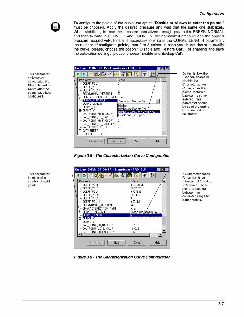
To configure the points of the curve, the option "Disable or Allows to enter the points "must be choosen. Apply the desired pressure and wait that the same one stabilizes.When stabilizing to read the pressure normalized through parameter PRESS_NORMALand then to write in CURVE_X and CURVE_Y, the normalized pressure and the appliedpressure, respectively. Finally is necessary to write in the CURVE_LENGTH parameter,the number of configured points, from 2 to 5 points. In case you do not desire to qualifythe curve, please, choose the option " Disable and Restore Cal". For enabling and savethe calibration settings, please, choose "Enable and Backup Cal".
Figure 3.5 - The Characterization Curve Configuration
Figure 3.6 - The Characterization Curve Configuration
This parameteractivates ordeactivates theCharacterizationCurve after thepoints have beenconfigured.
By the list box theuser can enable ordisable theCharacterizationCurve, enter thepoints, restore orbackup the curveentered. Thisparameter shouldbe used preferableby a method ofcalibration.
LD2EM305.CDR
Its CharacterizationCurve can have aminimum of 2 and upto 5 points. Thesepoints should bebetween thecalibrated range forbetter results.
This parameteridentifies thenumber of validpoints.
LD2EM306.CDR

LD302 – Operation and Maintenance Instruction Manual
3-8
Sensor Information
The main information about the transmitter can be accessed selecting the Transducerblock icon option as shown on the Figure 3.10 – Creating Transducers and FunctionBlocks. The sensor information will be displayed as shown below.
Figure 3.7 - Transducer Block - Sensor Information
Only application dependent options defined by combo boxes can be changed. (E.g.Flange Type, O' Ring Material, etc.) And the others are only factory configured (e.g.Sensor Isolating Diaphragm, Sensor Fluid, etc.).
Temperature Trim
Write in parameter TEMPERATURE_TRIM any value in the range -40°C to +85°C. Afterthat, check the calibration performance using parameter SECONDARY_ VALUE.
Figure 3.8 - The Temperature Trim Configuration
LD2EM307.CDR
This parameterassigns the E.U. for allparameters related tocalibration methods.Normally, they starttheir names with CAL_
The appropriatecalibration unit can bechoosen by selectingthe Engineering Unitsavailable for each typeof Transducer Block
By adjusting thisparameter to thecurrent temperature,the device'stemperatureindication isadjusted.
Normally, itsoperation isdone by amethod inthe factory.
LD2EM308.CDR

Configuration
3-9
Sensor Data Reading
All time that transmitter LD302 is on, is verified if the serial number of the sensor in thesensor board is the same that the recorded serial number in E2PROM in the main board.When these numbers are different (a swap of sensor set or main board was carriedthrough) the data stored in the E2PROM of sensor board is copied to the E2PROM of themain board.
Through the parameter BACKUP_RESTORE, also this reading can be made, choosingthe option "SENSOR_DATA_RESTORE". The operation, in this case, is madeindependent of the sensor serial number. Through the option"SENSOR_DATA_BACKUP", the sensor data stored in the main board Eeprom memorycan be saved in the E2PROM of the sensor board. (This operation is done at factory).
Through this parameter, we can recover default data from factory about sensor and lastsaved calibration settings, as well as making the rescue of calibrations. We have thefollowing options:
• Factory Cal Restore: Recover last calibration settings made at factory;• Last Cal Restore: Recover last calibration settings made by user and saved
as backup;• Default Data Restore: Restore all data as default;• Sensor Data Restore: Restore sensor data saved in the sensor board and copy
them to main board Eeprom memory.• Factory Cal Backup: Copy the actual calibration settings to the factory ones;• Last Cal Backup: Copy the actual calibration settings to the backup ones;• Sensor Data Backup: Copy the sensor data at main board Eeprom memory to the
Eeprom memory located at the sensor board;• None: Default value, no action is done.
Figure 3.9 - Transducer Block - Backup/Restore
LD2EM309.CDR
This parameter isused to save orrestore thedefault, factory oruser configurationstored at thesensor module.
Using its option,the user cansave his lastcalibrationsettings.
By selecting theoptions containedin the list box,operations ofbackup andrestore data in thesensor modulecan be selected.

LD302 – Operation and Maintenance Instruction Manual
3-10
Transducer Display – Configuration
Using the SYSCON is possible to configure the Display Transducer block. As the namedescribed it is a transducer due the interfacing of its block with the LCD hardware.
The Transducer Display is treated as a normal block by SYSCON. It means, this blockhas some parameters and those ones can be configured according to customer's needs.(See the Figure 3.10 – Creating Transducers and Function Blocks).
The customer can choose the parameters to be shown at LCD display, they can beparameters just for monitoring purpose or for acting locally in the field devices by using amagnetic tool.
Figure 3.10 – Creating Transducers and Function Blocks
Display Transducer Block
The local adjustment is completely configured by SYSCON. It means, the user can selectthe best options to fit his application. From factory, it is configured with the options to setthe Upper and Lower trim, for monitoring the input transducer output and check the Tag.Normally, the transmitter is much better configured by SYSCON, but the localfunctionality of the LCD permits an easy and fast action on certain parameters, since itdoes not rely on communication and network wiring connections. Among the possibilitiesby Local Adjustment, the following options can be emphasized: Mode block, Outputsmonitoring, Tag visualization and Tuning Parameters setting.
LD2EM310.CDR

Configuration
3-11
The interface between the user is described very detailed on the "General Installation,Operation and Maintenance Procedures Manual". Please take a detailed look at thismanual in the chapter related to "Programming Using Local Adjustment". It is significantlythe resources on this transducer display, also all the Series 302 field devices from SMARhas the same methodology to handle with it. So, since the user has learned once, he iscapable to handle all kind of field devices from SMAR.
All function block and transducers defined according Foundation Fieldbus have adescription of their features written on binary files, by the Device Description Language.
This feature permits that third parties configurator enabled by Device Description Servicetechnology can interpret these features and make them accessible to configure. TheFunction Blocks and Transducers of Series 302 have been defined rigorously accordingthe Foundation Fieldbus specifications in order to be interoperable to other parties.
In order to able the local adjustment using the magnetic tool, it is necessary to previouslyprepare the parameters related with this operation via SYSCON (System Configuration).The Figure 3.8 - The Temperature Trim Configuration and the Figure 3.9 - TransducerBlock - Backup/Restore show all parameters and their respective values, which shall beconfigured in accordance with the necessity of being locally adjusted by means of themagnetic tool. All values shown on the display are default values.
There are seven groups of parameters, which may be pre-configured by the user in orderto able, a possible configuration by means of the local adjustment. As an example, let’ssuppose that you don’t want to show some parameters; in this case, simply write aninvalid Tag in the parameter, Block_Tag_Param_X. Doing this, the device will not takethe parameters related (indexed) to its Tag as a valid parameters.
Definition of Parameters and Values
Block_Tag_ParamThis is the tag of the block to which the parameter belongs to use up to a maximum of 32characters.
Index_RelativeThis is the index related to the parameter to be actuated or viewed (0, 1, 2…). Refer tothe Function Blocks Manual to know the desired indexes, or visualize them on theSYSCON by opening the desired block.
Sub_IndexIn case you wish to visualize a certain tag, opt for the index relative equal to zero, and forthe sub-index equal to one (refer to paragraph Structure Block in the Function BlocksManual).
MnemonicThis is the mnemonic for the parameter identification (it accepts a maximum of 16characters in the alphanumeric field of the display). Choose the mnemonic, preferablywith no more than 5 characters because, this way, it will not be necessary to rotate it onthe display.
Inc_DecIt is the increment and decrement in decimal units when the parameter is Float or FloatStatus time, or integer, when the parameter is in whole units.
Decimal_Point_Numb.This is the number of digits after the decimal point (0 to 3 decimal digits).
AccessThe access allows the user to read, in the case of the “Monitoring” option, and to writewhen "action" option is selected, then the display will show the increment and decrementarrows.

LD302 – Operation and Maintenance Instruction Manual
3-12
Alpha_NumThese parameters include two options: value and mnemonic. In option value, it ispossible to display data both in the alphanumeric and in the numeric fields; this way, inthe case of a data higher than 10000, it will be shown in the alphanumeric field.
In option mnemonic, the display may show the data in the numeric field and themnemonic in the alphanumeric field.
In case you wish to visualize a certain tag, opt for the index relative equal to zero, and forthe sub-index equal to one (refer to paragraph Structure Block in the Function BlocksManual).
Figure 3.11 - Parameters for Local Adjustment Configuration
Figure 3.12 - Parameters for Local Adjustment Configuration
LD2EM311.CDR
LD2EM312.CDR

Configuration
3-13
Figure 3.13 - Parameters for Local Adjustment Configuration
Figure 3.14 - Parameters for Local Adjustment Configuration
LD2EM313.CDR
LD2EM314.CDR

LD302 – Operation and Maintenance Instruction Manual
3-14
Figure 3.15 - Parameters for Local Adjustment Configuration
Programming Using Local Adjustment
The local adjustment is completely configured by SYSCON. It means, the user can selectthe best options to fit his application. From factory, it is configured with the options to setthe Upper and Lower trim, for monitoring the input transducer output and check the Tag.Normally, the transmitter is much better configured by SYSCON, but the localfunctionality of the LCD permits an easy and fast action on certain parameters, since itdoes not rely on communication and network wiring connections. Among the possibilitiesby Local Adjustment, the following options can be emphasized: Mode block, Outputsmonitoring, Tag visualization and Tuning Parameters setting.
The interface between the user is also described very detailed on the "GeneralInstallation, Operation and Maintenance Procedures Manual" Please take a detailed lookat this manual in the chapter related to "Programming Using Local Adjustment". It issignificantly the resources on this transducer display, also all the Series 302 field devicesfrom SMAR has the same methodology to handle with it. So, since the user has learnedonce, he is capable to handle all kind of field devices from SMAR.
All function block and transducers defined according Foundation Fieldbus have adescription of their features written on binary files, by the Device Description Language.This feature permits that third parties configurator enabled by Device Description Servicetechnology can interpret these features and make them accessible to configure. TheFunction Blocks and Transducers of Series 302 have been defined rigorously accordingthe Foundation Fieldbus specifications in order to be interoperable to other parties.
The option "update"should be selected inorder to execute theupgrade of localadjustment programmingtree.After its step all theparameters selected willbe shown on the LCDdisplay.
This parameterupdates the localadjustmentprogramming treeconfigured on eachdevice.
LD2EM315.CDR

Configuration
3-15
Figure 3.16 - Step 1 - LD302
Figure 3.17 - Step 2 - LD302
Figure 3.18 - Step 3 - LD302
In order to start the localadjustment, place themagnetic tool in orifice Zand wait until letters MDare displayed.
Place the magnetictool in orifice S andwait during 5seconds.
LD2EM316.CDR
Insert themagnetic tool inorifice S oncemore and LOCADJ should bedisplayed.
Remove themagnetic toolfrom orifice S.
LD2EM317.CDR
In this option thefirst variable(P_VAL) isshowed with itsrespective value(if you to wantthat it keepsstatic, put the toolin S orifice andstay there.
Place the magnetic tool inorifice Z. In case this is thefirst configuration, theoption shown on thedisplay is the TAG with itscorresponding mnemonicconfigured by theSYSCOM. Otherwise, theoption shown on thedisplay will be the oneconfigured in the prioroperation. By keeping thetool inserted in this orifice,the local adjustment menuwill rotate.
LD2EM318.CDR

LD302 – Operation and Maintenance Instruction Manual
3-16
Figure 3.19 - Step 4 - LD302
Figure 3.20 - Step 5 - LD302
NOTE
This Local adjustment configuration is a suggestion only. Theuser may choose his preferred configuration via SYSCON,simply configuring the display block (See Programming UsingLocal Adjustment.)
In order to decrementthe lower value, placethe magnetic tool inorifice Z to shift thearrow to the downwardposition and then, byinserting and keepingthe tool in orifice S, itis possible todecrement the lowervalue.
In order to range thelower value(lower),simply insert themagnetic tool in orifice Sas soon as LOWER isshown on the display.An arrow pointingupward (↑↑↑↑) incrementsthe valve and an arrowpointing downward (↓↓↓↓)decrements the value. Inorder to increment thevalue, keep the toolinserted in S up to setthe value desired.
LD2EM319.CDR
In order to decrementthe upper value, placethe magnetic tool inorifice Z to shift thearrow to thedownward position anthen, by insetting andkeeping the tool inorifice S, it is possibleto decrement theupper value.
In order to range theupper value(upper),simply insert themagnetic tool in orificeS as soon as upper isshown on the display.An arrow pointingupward (↑↑↑↑) incrementsthe valve and an arrowpointing downward (↓↓↓↓)decrements the value.In order to incrementthe value, keep the toolinserted in S up to setthe value desired.
LD2EM320.CDR

Section 4
4-1
Maintenance Procedures
Disassembly Procedure
WARNING
Do not disassemble with power on.
The Figure 4.4 - Exploded View shows an exploded view of the transmitter and will helpto visualize the following:
Sensor Cleaning
In order to have access to the sensor (19) for cleaning purposes, the transmitter shouldbe removed from its process connections. The transmitter should be isolated from theprocess by means of manifolds or valves; then, the drain (13) must be opened to ventany remaining pressure.
Figure 4.1 - Sensor Rotation Stopper
After this, the transmitter may be removed from the standpipe. The flange bolts (16) maynow be loosened crosswise, one at a time. After removing bolts and flanges (15), theisolating diaphragms will be easily accessible for cleaning.
Cleaning should be done carefully in order to avoid damaging the delicate isolatingdiaphragms. Use of a soft cloth and a non-acid solution is recommended.
The oscillating circuit is a part of the sensor and the replacement of one implies replacingthe other.
To remove the sensor from the electronic housing, the electrical connections (in the fieldterminal side) and the main board connector must be disconnected.
Loosen the hex screw (20) and carefully unscrew the electronic housing from the sensor,observing that the flat cable is not excessively twisted.
LD2EM401.CDR

LD302 – Operation and Maintenance Instruction Manual
4-2
NOTE
The transmitters have a stopper that can be released to allowthe sensor to rotate more than one turn. (See Figure 4.1 -Sensor Rotation Stopper).
WARNING
Do not rotate the electronic housing more than 180° withoutdisconnecting the electronic circuit from the sensor and fromthe power supply.
Electronic Circuit
To remove the circuit board (5), loosen the two screws (3) that anchor the board.
WARNING
The board has CMOS components, which may be damaged byelectrostatic discharges. Observe correct procedures forhandling CMOS components. It is also recommended to storethe circuit boards in electrostatic-proof cases.
Pull the main board out of the housing and disconnect the power supply and the sensorconnectors.
Reassemble Procedure
WARNING
Do not assemble the main board with power on.
Sensor Mounting
When mounting the sensor (19), it is recommended to make use of a new set of gaskets(18 & 24) compatible with the process fluid. The bolts, nuts, flanges and other partsshould be inspected for corrosion or other eventual damage. Damaged parts should bereplaced.
NOTE
Backup Rings
High pressure transmitters A5, M5, M6 and High staticpressure transmitters H2, H3, H4, H5 and the sensors withtantalum diaphragm that use Buna-N or Viton O_Ring mustuse a metallic backup Ring (17) to prevent extrusion ofO_Ring. Do not use the backup O'Ring when the flange has aninsert of Kynar (PVDF).
Avoid bending the backup ring and inspect it for knots, cutsetc. Be careful when mounting it. The flat side, which shinesmore than the beveled side should be mounted against theO_Ring. (See Figure 4.2 - Backup Ring Mounting).

Maintenance Procedures
4-3
Gaskets should be lightly lubricated with silicone oil before they are fitted into theirrecesses. Use halogen grease for inert fill applications. The flanges should then bepositioned in order to press them in place. With the flanges holding the O-Rings in place,insert the four bolts (16) and tighten the nuts (23) finger tight, making sure the flangesremain parallel all the time.
• Tighten one nut till the flange seats.• Tighten the nut diagonally across with a torque of approximately 2.5 kgfm (20 ft. lbs).• Tighten the first nut with the same torque.• Verify the flange alignment.• Check torque on the four bolts.
If adapters (25) have been removed, it is recommended to replace gaskets (24) and toconnect the adapters to the process flanges before coupling them to the sensor.Optimum torque is 2.5 Kgf/m (20 ft.lbs).
The fitting of the sensor must be done with the main board out of the electronic housing.Mount the sensor to the housing turning clockwise until it stops. Then turn itcounterclockwise until it faces the protective cover (1) parallel to the process flange.Tighten the hex screw (20) to lock the housing to the sensor.
Figure 4.2 - Backup Ring Mounting
LD2EM402.CDR

LD302 – Operation and Maintenance Instruction Manual
4-4
Electronic Circuit
Plug sensor connector and power supply connector to main board.
Attach the display to the main board. Observe the four possible mounting positions.(Figure 4.3 - Four Possible Positions of the Display). The SMAR mark indicates upposition.
Figure 4.3 - Four Possible Positions of the Display
Anchor the main board and display with their screws (3).
After tightening the protective cover (1), mounting procedure is complete. The transmitteris ready to be energized and tested. It is recommended to open the transmitter's pressuretaps to atmosphere and adjust the TRIM.
Interchangeability
In order to obtain an accurate and better temperature compensated response. Eachsensor is submitted to a characterization process and the specific data is stored in anEEPROM located in the sensor body.
Every time the power is turned on, the main circuit reads the sensor serial number,should it differ from the number stored in the memory. The circuit understands that thereis a new sensor and the following information is transferred from the sensor to the maincircuit.
• Temperature compensation coefficients.• Sensor's trim, including 5-point characterization curve.• Sensor characteristics: type, range, diaphragm material and fill fluid.
The other transmitter characteristics are stored in the main circuit memory and are notaffected by sensor change.
LD2EM403.CDR

Maintenance Procedures
4-5
Upgrading LD301 to LD302
The sensor and casing of the LD301 is exactly the same as the LD302. By changing thecircuit board of the LD301 it becomes a LD302. The display on LD301 version 5.XX, isthe same as on LD302 and can therefore be used with the LD302 upgrade circuit board.With a LD301 version three or earlier, that display can not be used.
Upgrading the LD301 to a LD302 is therefore very much the same as the procedure forreplacing the main board described above.
To remove the circuit board (5), loosen the two screws (3) that anchor the board.
Caution with the circuit boards must be taken as mentioned above.
Pull the LD301 main board out of the housing and disconnect the power supply and thesensor connectors.
Put in the LD302 main board reversing the procedure for removing the LD301 circuit.
Returning Materials
Should it become necessary to return the transmitter to SMAR, simply contact our office,informing the defective instrument's serial number, and return it to our factory.
In order to speed up analysis and solution of the problem, the defective item should bereturned with a description of the failure observed, with as much details as possible.Other information concerning to the instruments operation, such as service and processconditions, are also helpful.
ACCESSORIES
ORDERING CODE DESCRIPTION
SD1 Magnetic Tool for Local Adjustment
BC1 Fieldbus/RS232 Interface
SYSCON System Configurator
PS302 Power Supply
BT302 Terminator
PCI Process Control Interface

LD302 – Operation and Maintenance Instruction Manual
4-6
Figure 4.4 - Exploded View
LD2EM404.CDR

Maintenance Procedures
4-7
SPARE PARTS LIST
DESCRIPTION OF PARTS POSITION CODE
HOUSING, Aluminum (NOTE 2)
½ - 14 NPT 7 304-0130
M20 x 1.5 7 304-0131
PG 13.5 DIN 7 304-0132
HOUSING, 316 SS (NOTE 2)
½ - 14 NPT 7 304-0133
M20 x 1.5 7 304-0134
PG 13.5 DIN 7 304-0135
COVER (INCLUDES O'RING)
Aluminum 1 and 12 204-0102
316 SS 1 and 12 204-0105
COVER WITH WINDOW FOR INDICATION (INCLUDES O’RING)
Aluminum 1 204-0103
316 SS 1 204-0106
COVER LOCKING SCREW 6 204-0120
SENSOR LOCKING SCREW 20 204-0121
EXTERNAL GROUND SCREW 22 204-0124
IDENTIFICATION PLATE FIXING SCREW 9 204-0116
DIGITAL INDICATOR 4 214-0108
TERMINAL INSULATOR 10 304-0123
MAIN ELECTRONIC CIRCUIT BOARD (GLL 892) 5 304-0130
FLANGE (WITH HOLE FOR DRAIN/VENT)
Plated Carbon Steel 15 204-0501
Stainless Steel 316 15 204-0502
Hastelloy C276 15 204-0503
Monel 400 15 204-0504
FLANGE (WITHOUT HOLE FOR DRAIN/VENT)
Plated Carbon Steel 15 204-0511
Stainless Steel 316 15 204-0512
Hastelloy C276 15 204-0513
Monel 400 15 204-0514
BLANK FLANGE (FOR GAGE AND ABSOLUTE MODELS)
Plated Carbon Steel 15 204-1101
Stainless Steel 316 15 204-1102
ADAPTER
Plated Carbon Steel 25 203-0601
Stainless Steel 316 25 203-0602
Hastelloy C276 25 203-0604
Monel 400 25 203-0604
O’RINGS (NOTE 3)
Cover, Buna-N 2 204-0122
Neck, Buna-N 21 204-0113

LD302 – Operation and Maintenance Instruction Manual
4-8
SPARE PARTS LIST
DESCRIPTION OF PARTS POSITION CODE
O’RINGS (NOTE 3)
Flange, BUNA-N 18 203-0401
Flange, VITON 18 203-0402
Flange, TEFLON 18 203-0403
Flange, ETHYLENE/PROPYLENE 18 203-0404
Flange, TEFLON with spring LOADED 18 203-0405
Adapter, BUNA-N 24 203-0701
Adapter, VITON 24 203-0702
Adapter, TEFLON 24 203-0703
Adapter, ETHYLENE/PROPYLENE 24 203-0704
BACKUP RING (NOTE 3) 17 203-0710
TERMINAL HOLDING SCREW.
Housing in Aluminum 11 304-0119
Housing in 316 Stainless Steel 11 204-0119
MAIN BOARD SCREW HOUSING IN ALUMINUM
Units with indicator 3 304-0118
Units without indicator 3 304-0117
MAIN BOARD SCREW HOUSING IN 316 STAINLESS STEEL
Units with indicator 3 204-0118
Units without indicator 3 204-0117
FLANGE BOLT
Carbon Steel 16 203-0300
Stainless Steel 316 16 203-0310
FLANGE NUT
Carbon Steel 23 203-0302
Stainless Steel 316 23 203-0312
ADAPTER BOLT
Carbon Steel 26 203-0350
Stainless Steel 316 26 203-0351
DRAIN/VENT SCREW
Stainless Steel 316 13 203-1401
Hastelloy C276 13 203-1402
Monel 400 13 203-1403
FLANGE PLUG (STOPPER)
Stainless Steel 316 14 203-0552
Hastelloy C276 14 203-0553
Monel 400 14 203-0554
MOUNTING BRACKET FOR 2” PIPE MOUNTING (NOTE 5)
Carbon Steel - 203-0801
Stainless Steel 316 - 203-0802
Carbon Steel with bolts, nuts, washers and U-clamp in 316SS - 203-0803
LOCAL ADJUSTMENT PROTECTION CAP 8 204-0114
SENSOR 19 (NOTE 4)
Table 4.1 - Spare Part List

Maintenance Procedures
4-9
NOTE
1. For category A, it is recomended to keep, in stock, 25 partsinstalled for each set, and for category B, 50.
2. Includes Terminal Block, Bolts, caps and Identification platewithout certification.
3. 0-Rings and Backup Rings are packaged in packs of 12units.
4. To specify sensors, use the following tables.5. Including U-clamp, nuts, bolts and washers.
204-0301 SPARE PART NUMBER FOR DIFFERENTIAL, GAGE, ABSOLUTE AND HIGH STATIC PRESSURE TRANSMITTERS
CODE Type and Range
D1D2D3D4
M1M2M3M4M5M6
A2A2A3A4A5
H2H3H4H5
Differential 0.125 to 5 kPa 0.5 to 20 inH2ODifferential 1.25 to 50 kPa 5 to 200 inH2ODifferential 6.25 to 250 kPa 25 to 1000 inH2ODifferential 62.5 to 2500 kPa 9 to 360 psi
Gage 0.125 to 5 kPa 0.5 to 20 inH2OGage 1.25 to 50 kPa 5 to 200 inH2OGage 6.25 to 250 kPa 25 to 1000 inH2OGage 62.5 to 2500 kPa 9 to 360 psiGage 0.625 to 25 MPa 90 to 3600 psiGage 1 to 40 MPa 145 to 5800 psi
Absolute 0.5 to 5 kPa 3.7 to 37 psiaAbsolute 2.5 to 50 kPa 0.36 to 7.2 psiaAbsolute 6.25 to 250 kPa 0.9 to 36 psiaAbsolute 62.5 to 2500 kPa 9 to 360 psiaAbsolute 0.625 to 25 MPa 90 to 3600 psia
Differential – High Static Pressure 1.25 to 50 kPa 5 to 200 inH2ODifferential – High Static Pressure 6.25 to 250 kPa 25 to 1000 inH2ODifferential – High Static Pressure 62.5 to 2500 kPa 9 to 360 psiDifferential – High Static Pressure 0.625 to 25 MPa 90 to 3600 psi
CODE Diaphragm (s) Material and Fill Fluid (1) (2) (3)
1234578Z
316L SST Silicone Oil316L SST Fluorolube OilHastelloy C276 Silicone OilHastelloy Fluorolube OilMonel 400 Silicone OilTantalum Silicone OilTantalum Fluorolube OilOthers – Specify
LD302 D2 H1/A1
(1) Tantalum and Monel diaphragm are not availablefor Range 1.(2) Absolute Models are not available with Tantalum diaphragms or Fluorolube Oil.(3) Tantalum.sensors wil be sent with backup ring. They must be used when Viton or Buna_N O_Rings are used. Do not use the backup ring with Teflon rings or Kynar insert in the
process flanges.

LD302 – Operation and Maintenance Instruction Manual
4-10
204-0301 SPARE PART NUMBER FOR LEVEL SENSORS
CODE Range
L2L3L4
Level 1.25 to 50 kPa 5 to 200 inH2OLevel 6.25 to 250 kPa 25 to 1000 inH2OLevel 62.5 to 2500 kPa 9 to 360 psi
CODE Diaphragm (s) Material and Fill Fluid (1)
1234578Z
316L SST Silicone Oil316L SST Fluorolube OilHastelloy C276 Silicone Oil (2)Hastelloy C276 Fluorolube Oil (2)Monel 400 Silicone OilTantalum Silicone OilTantalum Fluorolube OilOthers – Specify
CODE Flange (s), Adapter (s) and Drain/Vent Valves Material
CIHMNZ
Plated CS (Drain/Vent in Stainless Steel)316L SSTHastelloy C276 (2)Monel 400316 SST (Drain/Vent in Hastelloy C276) (2)Others – Specify
CODE Wetted 0-Rings Materials
0BVTZ
Without 0-Rings (Remote Seal)Buna NVitonTeflonOthers – Specify
CODE Drain/Vent Position
0UD
Without Drain/Vent Note: For better drain/vent operation, the side vent or drain valves are standard.Upper If drain/vent valves are not required, use code 0.Lower
CODE Process Connection (Low Side)
01Z
¼ - 18 NPT (Without Adapter)1/2 - 14 NPT (With Adapter)Others – Specify
CODE Process Connection (Mounting Flange)
1234678Z
3" 150# (ANSI B16.5)3" 300# (ANSI B16.5)4" 150# (ANSI B16.5)4" 300# (ANSI B16.5)DN 80 PN 25/40DN 100 PN 10/16DN 100 PN 25/40Others - Specify
CODE Flange Material (Level Tap)
12Z
Plated CS316 SSTOthers – Specify
CODE Extension Length
01234Z
0 mm 50 mm (2")100 mm (4")150 mm (6")200 mm (8")Others – Specify
CODE Diaphragm and Extension Materials (Level Trap)
1234Z
316L SSTHastelloy C276 (2)Monel 400 (3) Note: With 316L SST extension.TantalumOthers – Specify
CODE Fill Fluid (Level Tap)
123Z
Silicone OilFluorolube OilDC704 Silicone OilOthers – Specify
CODE Other Special Feature
0Z
Without Special FeatureWith Other Special Feature –Specify
LD302 L2 1 I B U 1 0 0 2 2 1 1 H1/A1
(1) Tantalum sensors will be sent with backup ring. They must be used when Viton or Buna_N O_Rings are used. Do not use the backup ring with Teflon rings or Kynar insert in theprocess flanges.
(2) Meets nace material recommendations per MR-01-75(3) Fluorolube fill fluid is not available for Monel Diaphragm.

Section 5
5-1
Technical Characteristics
Functional Specifications
Process FluidLiquid, gas or vapor.
Output SignalDigital only. Fieldbus, 31.25 kbit/s voltage mode with bus power.
Power SupplyBus power 9 - 32 VDC.Current consumption quiescent 12 mA.Output impedance: nonintrinsic safety from 7.8 kHz - 39 kHz should be greater or equalto 3 kOhm.Intrinsic safety output impedance (assuming an IS barrier in the power supply) from 7.8kHz - 39 kHz should be greater or equal to 400 Ohm.
IndicatorOptional 4½-digit numerical and 5-character alphanumerical LCD indicator.
Hazardous Area CertificationsExplosion proof, weather proof and intrinsically safe (CENELEC and FM standards).
Temperature LimitsAmbient: -40 to 85 ºC (-40 to 185 ºF).Process: -40 to 100 ºC (-40 to 212 ºF) (Silicone Oil).
0 to 85 ºC (-32 to 185 ºF) (Fluorolube Oil).-40 to 150 ºC (-40 to 302 ºF) for LD302L.-25 to 85 ºC (-13 to 185 ºF)(Viton O-Rings).
Storage: -40 to 100 ºC (-40 to 212 ºF).Display: -10 to 60 ºC ( 14 to 140 ºF) operation.
-40 to 85 ºC (-40 to 185 ºF) without damage.
Turn-on TimePerforms within specifications of less than 5.0 seconds after power is applied to thetransmitter.
Volummetric DisplacementLess than 0.15 cm3 (0.01 in3).
Overpressure and Static Pressure LimitsFrom 3.45 kPa abs. (0.5 psia)* to:8 MPa (1150 psi) for range 1.16 MPa (2300 psi) for ranges 2, 3, 4 & 5.32 MPa (4600 psi) for models H & A5.40 MPa (5800 psi) for model M5.52 MPa (7500 psi) for model M6.
* except the LD302A model.
For ANSI/DIN Level flanges (LD302L models):150 lb Flanges: 6 psia to 275 psi at 100 °F.300 lb Flanges: 6 psia to 720 psi at 100 °F.600 lb Flanges: 6 psia to 1440 psi at 100 °F.PN10/16: -60 kPa to 2,8 MPa at 38 °C.PN25/40: -60 kPa to 9 MPa at 38 °C.
These overpressures will not damage the transmitter, but a new calibration may benecessary.

LD302 – Operation and Maintenance Instruction Manual
5-2
Flange Test Pressure: 60 MPa (8570 psi).
Humidity Limits0 to 100% RH.
Performance Specifications
Reference conditions: range starting at zero, temperature 25 ºC (77 ºF), atmosphericpressure, power supply of 24 Vdc, silicone oil fill fluid, isolating diaphragms in 316L SSand digital trim equal to lower and upper range values.
Accuracy±0.075% of span (for span 0.1 URL).±0.0375 [1+ (0.1 URL/SPAN)]% of span (for span <0.1 URL).
For range 5 and 6, Absolute models, diaphragms in Tantalum, Monel or fill fluid inFluorolube:±0.1% of span (for span 0.1 URL).±0.05 [1+ (0.1 URL/SPAN)]% of span (for span <0.1 URL).
For Absolute - range 1:±0.2% of span
Linearity, hysteresis and repeatability effects are included.
Stability±0.1% of URL for 24 months for ranges 2, 3, 4, 5 & 6.±0.2% of URL for 12 months for range 1 & L models.±(0.25% of URL for 5 years at 20 ºC temperature change and up to 70 bar of staticpressure.
Temperature Effect±(0.02% × URL+0.1% × span) per 20 ºC (36 ºF) for ranges 2, 3, 4 & 5.±(0.05% × URL+0.15% × span) per 20 ºC (36 ºF) for range 1 & level models.
Static Pressure EffectZero error:±0.1% URL per 7 MPa (1000 psi) for ranges 2, 3, 4 & 5 or 3.5 MPa (500 psi) for Lmodels.±0.1% URL per 1.7 MPa (250 psi) for range 1.
This is a systematic error that can be eliminated by calibrating at the operating staticpressure.
Span error:Correctable to ±0.2% of reading per 7 MPa (1000 psi) for ranges 2, 3, 4 and 5, and 3,5MPa (500 psi) for range 1 and level models.
Power Supply Effect±0.005% of calibrated span per volt.
Mounting Position EffectZero shift of up to 250 Pa (1 inH2O) which can be calibrated out. No span effect.
Electro-Magnetic Interference EffectDesigned to comply with IEC 801.

Technical Characteristics
5-3
Physical Specifications
Electrical Connection½ -14 NPT, Pg 13.5, or M20 × 1.5 metric. Other connections or request.
Process Connection¼ -18 NPT or ½ -14 NPT (with adapter).For L models see Ordering Code.
Wetted Parts
Isolating Diaphragms316L SST, Hastelloy C276, Monel 400 or Tantalum.
Drain/Vent Valves and Blind Plug316 SST, Hastelloy C276 or Monel.
FlangesPlated carbon steel, 316 SST, Hastelloy C276 or Monel.
Wetted O-Rings (For Flanges and Adapters)Buna N, Viton™ or PTFE. Ethylene-Propylene on request.
The LD302 is available in materials conforming to NACE MR-01-75.
Nonwetted Parts
Electronic HousingInjected aluminum with polyester painting or 316 SST (NEMA 4X, IP67).
Blank FlangePlated carbon steel, when the wetted flange is made of this same material, and 316 SSTin the other cases.
Level Flange (LD302L) Material316 SST.
Fill FluidSilicone or Fluorolube Oil.
Cover O-RingsBuna N.
Mounting BracketPlated carbon steel with polyester painting or 316 SST.Accessories (bolts, nuts, washers and U-clamp) in carbon steel or 316 SST.
Flange Screws, Bolts and nutsPlated carbon steel, Grade 7 or 316 SST.
Identification Plate316 SST.
Mountinga) Flange mounted for models LD302L.b) Optional universal mounting bracket for surface or vertical/horizontal 2"-pipe (DN 50).c) Via bracket on manifold valve (Optional).d) Directly on piping for closely coupled transmitter/ orifice flange combinations.

LD302 – Operation and Maintenance Instruction Manual
5-4
Approximate Weights3.15 kg (7 lb) : all models, except level transmitters.5.85 to 9.0 kg (13 lb. to 20 lb): level transmitter depending on the flanges, extension andmaterials.
Hastelloy is a trademark of the Cabot Corp.Viton and Teflon are trademarks of E. I. DuPont de Nemours & Co.Fluorolube is a trademark of Hooker Chemical Corp.Monel is a trademark of International Nickel Co.

Technical Characteristics
5-5
MODELLD302 DIFFERENTIAL, GAGE, ABSOLUTE AND HIGH STATIC PRESSURE TRANSMITTERS
CODE Type and Range
D1D2D3D4
M1M2M3M4M5M6
A2A2A3A4A5
H2H3H4H5
Differential 0.125 to 5 kPa 0.5 to 20 inH2ODifferential 1.25 to 50 kPa 5 to 200 inH2ODifferential 6.25 to 250 kPa 25 to 1000 inH2ODifferential 62.5 to 2500 kPa 9 to 360 psi
Gage 0.125 to 5 kPa 0.5 to 20 inH2OGage 1.25 to 50 kPa 5 to 200 inH2OGage 6.25 to 250 kPa 25 to 1000 inH2OGage 62.5 to 2500 kPa 9 to 360 psiGage 0.625 to 25 MPa 90 to 3600 psiGage 1 to 40 MPa 145 to 5800 psi
Absolute 0.5 to 5 kPa 3.7 to 37 psiaAbsolute 2.5 to 50 kPa 0.36 to 7.2 psiaAbsolute 6.25 to 250 kPa 0.9 to 36 psiaAbsolute 62.5 to 2500 kPa 9 to 360 psiaAbsolute 0.625 to 25 MPa 90 to 3600 psia
Differential – High Static Pressure 1.25 to 50 kPa 5 to 200 inH2ODifferential – High Static Pressure 6.25 to 250 kPa 25 to 1000 inH2ODifferential – High Static Pressure 62.5 to 2500 kPa 9 to 360 psiDifferential – High Static Pressure 0.625 to 25 MPa 90 to 3600 psi
CODE Diaphragm (s) Material and Fill Fluid (2) (3)
1234578Z
316L SST Silicone Oil316L SST Fluorolube OilHastelloy C276 Silicone Oil* (2) Absolute Models are not available with Tantalum diaphragms or Fluorolube Oil.Hastelloy Fluorolube Oil*Monel 400 Silicone Oil (3) Tantalum and Monel diaphragm are not available for Range 1.Tantalum Silicone OilTantalum Fluorolube OilOthers – Specify
CODE Flange(s), Adapter(s) and Drain/Vent Valves Material
IHMNZ
Plated CS (Drain/Vent in Stainless Steel)316 SSTHastelloy C276*Monel 400316 SST (Drain/Vent in Hastelloy C276)*Others – Specify
CODE Wetted 0-Rings Materials (4)
0BVTZ
Without 0-RingsBuna NViton (4) O-Rings are not available on sides with Remote Seals.TeflonOthers – Specify
CODE Drain/Vent Position (5) (6)
0UD
Without Drain/Vent (5) For better drain/vent operation, vent valves are strongly recommended.UpperLower (6) Drain/Vent valve not available on sides with Remote Seal.
CODE Local Indicator
01
Without IndicatorWith Digital Indicator
CODE Process Connections
01RZ
1/4 - 18 NPT (Without Adapter)1/2 - 14 NPT (With Adapter)Remote Seal (Specify)Others – Specify
CODE Electrical Connections
0AB
1/2-14 NPTM20 x 1.5Pg 13.5 DIN
CODE Mounting Bracket for 2" Pipe or Surface Mounting
0127
Without BracketCarbon Steel Bracket316 SST BracketCarbon Steel bracket with 316 SST fasteners
CODE Options
H1A1C1ZZ
316 SST Housing316 SST Bolts and Nuts*Special CleaningSpecial Options – Specify
LD302 D2 1 I B U 1 0 0 2 H1/A1
(1) The upper range limit can be extend up to 1.2 times with a small degradation of accuracy. * Meets NACE material recommendations per MR-01-75

LD302 – Operation and Maintenance Instruction Manual
5-6
MODELLD302 LEVEL TRANSMITTERS
CODE Range
L2L3L4
Level 1.25 to 50 kPa 5 to 200 inH2OLevel 6.25 to 250 kPa 25 to 1000 inH2OLevel 62.5 to 2500 kPa 9 to 360 psi
CODE Diaphragm Material and Fill Fluid (Low Side)
1234578Z
316L SST Silicone Oil316L SST Fluorolube OilHastelloy C276 Silicone Oil*Hastelloy C276 Fluorolube Oil*Monel 400 Silicone OilTantalum Silicone OilTantalum Fluorolube OilOthers – Specify
CODE Flange, Adapter and Drain/Vent Valves Material (Low Side)
CIHNZ
Plated CS (Drain/Vent in Stainless Steel)316L SSTHastelloy C276*316 SST (Drain/Vent in Hastelloy C276)*Others – Specify
CODE Wetted 0-Rings Material (Low Side)
0BVTZ
Without 0-Rings (Remote Seal)Buna NVitonTeflonOthers – Specify
CODE Drain/Vent Position (Low Side)
0UD
Without Drain/Vent Note: For better drain/vent operation, the side vent or drain valves are standard .Upper If drain/vent valves are not required, use code 0.Lower
CODE Local Indicator
01
Without IndicatorWith Digital Indicator
CODE Process Connection (Low Side)
01RZ
¼ - 18 NPT (Without Adapter)1/2 - 14 NPT (With Adapter)Remote Seal (Specify)Others – Specify
CODE Electrical Connections
0AB
1/2-14 NPTM20 x 1.5Pg 13.5 DIN
CODE Process Connection (High Side)
12346789
3" 150# (ANSI B16.5 RF)3" 300# (ANSI B16.5 RF)4" 150# (ANSI B16.5 RF)4" 300# (ANSI B16.5 RF)DN 80 PN 25/40DN 100 PN 10/16DN 100 PN 25/402" 150# (ANSI B16.5 RF)
ABCDEZ
2" 300# (ANSI B16.5 RF)2" 600# (ANSI B16.5 RF)3" 600# (ANSI B16.5 RF)4" 600# (ANSI B16.5 RF)DN 50 PN 10/40Others – Specify
CODE Extension Length
01234Z
0 mm 50 mm (2") Note: With 316L SST extension.100 mm (4")150 mm (6")200 mm (8")Others – Specify
CODE Diaphragm Material (High Side)
12345Z
316L SSTHastelloy C276*Monel 400**TantalumTitaniumOthers – Specify
CODE Fill Fluid (High Side)
123AZ
DC200 Silicone OilFluorolube OilDC704 Silicone OilDC200/350 Silicone Oil –Food gradeOthers – Specify
CODE Options
H1A1C1ZZ
316 SST Housing316 SST Bolts and Nuts*Special CleaningSpecial Options – Specify
LD302 L2 1 I B U 1 0 0 2 2 1 1 H1/A1
* Meets NACE material recommendations per MR-01-75 **Fluorolube fill fluid is not available for Monel Diaphragm.

Technical Characteristics
5-7
LD2EM501.CDR

LD302 – Operation and Maintenance Instruction Manual
5-8


