1 PLEASE READ THESE INSTRUCTIONS BEFORE INSTALLATION WEB SITE REFERENCE: www.grubeeinc.com Instructions Copy Righted: Rev. 2011 YuanDong SkyHawk Engine Parts Kit: GT5 > 66cc / 47mm x 38mm bore and stroke: Sq. Head; > Chinese erroneously call this engine 80cc: Gt2B > 48cc 40mm x 38mm bore and stroke: Rd. Head. > Old timers call this engine a WingDing. Kit Box Contents for distribution in Canada only: 48cc or 66cc 2 cycle gas engine with dual needle bearing: Black Catalytic exhaust muffler; 2.5L Fuel Tank plated inside; Drive chain; Chain guard; 44T Wheel Sprocket with 9 hole mounting hardware for 36 spoke wheel; Ball Bearing Chain idler: Push button clutch lever, Carburetor. CD Ignition module, Throttle w/ integral kill switch: Tool kit with extra spark plug & gaskets; Extra mt. block, Extra head gasket: Note: This is a Do it Yourself Kit: The End User or the Installer becomes the vehicle manufacture and assumes all laws of the land including any product liability. Do not use or buy this product if you expect otherwise. Mechanical aptitude and working ability is required to perform this installation. Many “do it yourself” backyard mechanics will find this project rewarding. A love of small engines is the only required catalyst for this project. However, installation is sometimes best done by a professional auto or motorcycle mechanic. WARNING: Do not use a donor bike with front and rear fenders as side holding struts can come loose and lodge in wheel spokes causing danger to rider. Frame size should have a 70 degree included V angle w9ith down-tube of 28 to 32mm dia. and seat tube of 28 to 30mm dia. For sufficient engine clearance select a bike with a seat tube length of at least 12 ½ inches measured between bottom of top tube and top of pedal sprocket tube. Using a bike coaster brake only is not recommended as chain can break leaving no brake at all. Use a bike with front and rear brakes to ensure best stopping ability; A rewarding joy and challenge is found in designing a custom installation of your own. Remember, a quality installation and daily maintenance is paramount to safe usage and long term satisfaction. You may find many uses for this engine such as power for a stationary machine or for other off road riding machines. Have fun and good luck on your motorized project. Happy trails to you from Don & Angel at GruBee/China GAS: STEP #1 Mounting the Engine: 1. The engine mounts in a “Vee” frame. It is best to make sure all 4 engine studs are securely bottomed out in the engine before mounting. Use a double nut “Jam Nut” procedure to tighten.
Transcript
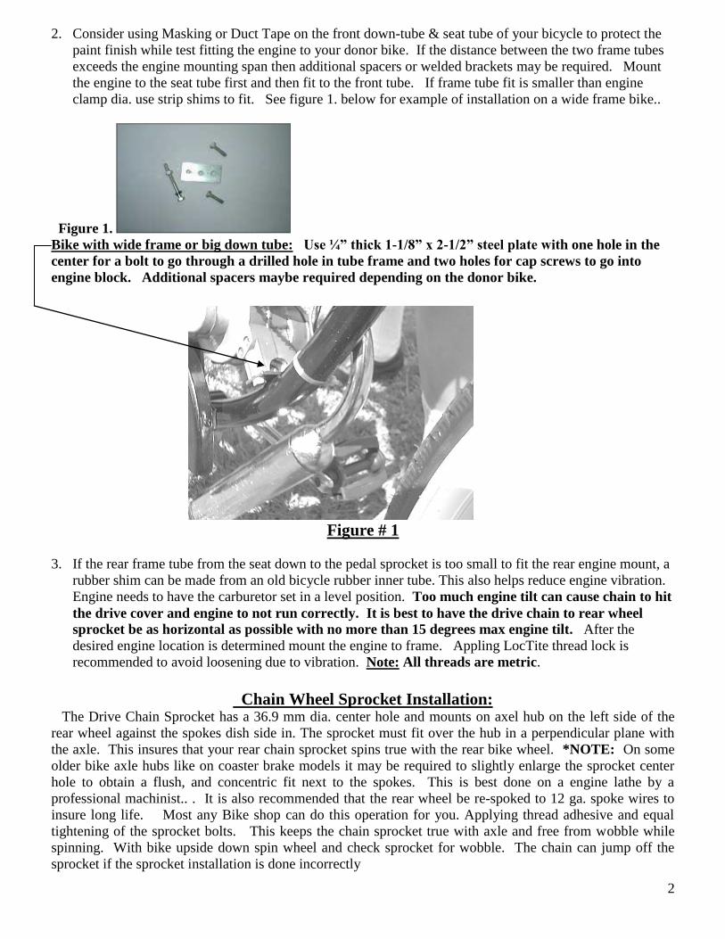
1
PLEASE READ THESE INSTRUCTIONS BEFORE INSTALLATION
WEB SITE REFERENCE: www.grubeeinc.com Instructions Copy Righted: Rev. 2011
YuanDong SkyHawk Engine Parts Kit:
GT5 > 66cc / 47mm x 38mm bore and stroke: Sq. Head; > Chinese erroneously call this engine 80cc:
Gt2B > 48cc 40mm x 38mm bore and stroke: Rd. Head. > Old timers call this engine a WingDing.
Kit Box Contents for distribution in Canada only:
48cc or 66cc 2 cycle gas engine with dual needle bearing: Black Catalytic exhaust muffler; 2.5L Fuel Tank
plated inside; Drive chain; Chain guard; 44T Wheel Sprocket with 9 hole mounting hardware for
HD axle kits: HD axle pre-installed in Wheel for drop in fit. Bike frame with built in gas tank
5 Steel
plates:
9 - 4.8
grade M6
bolts with
lock nuts
2 rubber
cushions.
4
The drive chain can be easily shortened to the correct length. Special tools are required to remove and
replace the master link when shortening the chain by removing links. Ideally, both your pedal drive chain
and your engine drive chain should have the same tension.
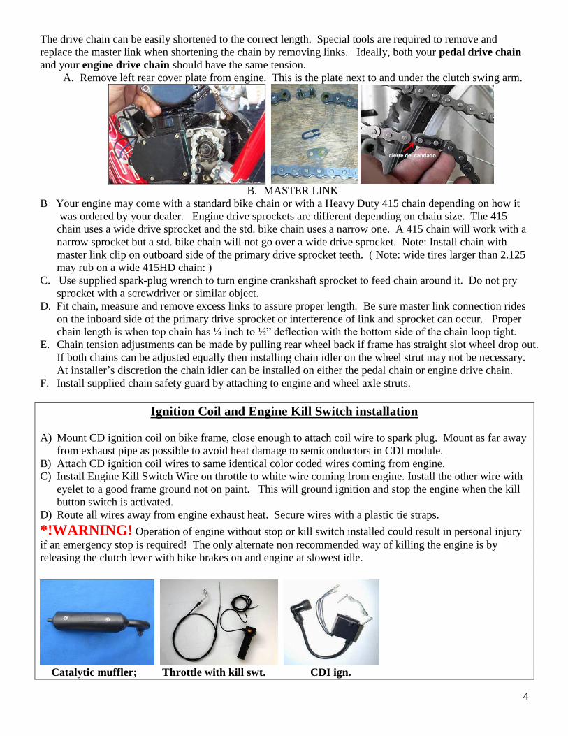
A. Remove left rear cover plate from engine. This is the plate next to and under the clutch swing arm.
B. MASTER LINK
B Your engine may come with a standard bike chain or with a Heavy Duty 415 chain depending on how it
was ordered by your dealer. Engine drive sprockets are different depending on chain size. The 415
chain uses a wide drive sprocket and the std. bike chain uses a narrow one. A 415 chain will work with a
narrow sprocket but a std. bike chain will not go over a wide drive sprocket. Note: Install chain with
master link clip on outboard side of the primary drive sprocket teeth. ( Note: wide tires larger than 2.125
may rub on a wide 415HD chain: )
C. Use supplied spark-plug wrench to turn engine crankshaft sprocket to feed chain around it. Do not pry
sprocket with a screwdriver or similar object.
D. Fit chain, measure and remove excess links to assure proper length. Be sure master link connection rides
on the inboard side of the primary drive sprocket or interference of link and sprocket can occur. Proper
chain length is when top chain has ¼ inch to ½” deflection with the bottom side of the chain loop tight.
E. Chain tension adjustments can be made by pulling rear wheel back if frame has straight slot wheel drop out.
If both chains can be adjusted equally then installing chain idler on the wheel strut may not be necessary.
At installer’s discretion the chain idler can be installed on either the pedal chain or engine drive chain.
F. Install supplied chain safety guard by attaching to engine and wheel axle struts.
Ignition Coil and Engine Kill Switch installation
A) Mount CD ignition coil on bike frame, close enough to attach coil wire to spark plug. Mount as far away
from exhaust pipe as possible to avoid heat damage to semiconductors in CDI module.
B) Attach CD ignition coil wires to same identical color coded wires coming from engine.
C) Install Engine Kill Switch Wire on throttle to white wire coming from engine. Install the other wire with
eyelet to a good frame ground not on paint. This will ground ignition and stop the engine when the kill
button switch is activated.
D) Route all wires away from engine exhaust heat. Secure wires with a plastic tie straps.
*!WARNING! Operation of engine without stop or kill switch installed could result in personal injury
if an emergency stop is required! The only alternate non recommended way of killing the engine is by
releasing the clutch lever with bike brakes on and engine at slowest idle.
Catalytic muffler; Throttle with kill swt. CDI ign.
5
Push button Clutch lever: Optional Dual lever Clutch & Brake Clutch cable end locks in lever handle.
Clutch cable installation and adjustment:
A) Install clutch lever to left side of handlebar and attach cable end barrel into lever slot hole.
B) Squirt oil down the cable sleeve: Route clutch cable through the ball-mount on motor with the big spring
around the cable jacket and ahead of the ball mount. The big spring serves as a cable heat shield.
C) Insert cable wire through small spring and route through clutch arm and attach brass cable-end and
screw. Adjust cable tension to allow very slight play in arm. Handlebar clutch lever must be in the
released or outward position to complete this operation.
D) Activate lever a few times, and check clutch arm for slight free play: About 1/16” engine clutch arm
free play is required with the handle bar lever in the released in what is called clutch engaged
position or the engine will fail to start if cable is too loose or if too tight. Re-adjust as required.
E) Basics of clutch operation: The handlebar lever pulls the cable that moves the engine clutch arm. In turn
the clutch arm pushes a rod through the motor that pushes the clutch plate out. ( similar to a car clutch.)
Releasing the handle bar lever engages the clutch and provides engine torque to the drive chain or to start
the engine. The clutch friction allows engine to start, and also transmits engine torque to the drive chain.
When the bike is in the pedal mode the handle bar clutch lever is locked inward in the catch notch. The
bike then operates in default as it would without any engine. Periodic clutch adjustment is necessary to
maintain efficient operation *NOTE: Cut off excess cable from clutch arm, before operation, to avoid
possible interference with pedals, chain, your legs, etc. See Figure #4.
Clutch arm: Clutch cable Note brass screw lock at the end;
Figure #4 Additional cable adjustment can be made at a mid cable joint if your kit is so equipped.
Note that lever is parallel with side
of engine when clutch is engaged.
6
NOTE: If Clutch cable is not adjusted correctly the engine will not start. Check for slight clutch cable
arm free play with handle bar lever released which would be in the clutch engaged position.
Carburetor and Throttle Installation
OPTIONAL NEW STYLE THROTTLE
with kill switch:
Kill switch; one wire goes to white wire
from engine and the other to frame grd.
Drill small hole in handle bar for pin lock.
Install CDI module on down tube as far away from engine heat as possible.
First install Blue & Black wires from engine magneto to same color CDI wires. Warning:
Do not hook up backwards or damage will occur to the CDI. Next install the throttle
handle kill switch wires into the 2 remaining open holes of the 2 CDI wire terminals. Push
the clear rubber protectors over the 2 connections and tape with black electrical tape. The
remaining white wire from the engine is not needed unless you want to run a small wattage
6V headlight but it’s not recommended as it will rob engine ignition power requirements so is
Blk. wire from engine to Blk. of CDI
Blue wire from engine to Blue of CDI
Two kill switch wires can go to either of the remaining 2
empty holes of the CDI terminals: Color code not important.
For CDI Color code is very important:
Like to Like.
7
really best to tape this wire up securely or just snip it off at the engine exit plug. To keep
water out of the magneto box use a heat shrink tube over the wire sheathing.
The “Magneto” is the heart of the ignition system and is activated by rotation of a permanent
magnet rotor. When a N/S magnetic flux field rotates past the magneto coil an induced
voltage is sent to the CDI via blue / black wires so as to fire the spark plug at the right time.
Engine firing timing is not adjustable; Position of p/m rotor is fixed to ensure correct timing.
If engine does not fire at start up check all bullet connections. Check if kill switch has an
unwanted ground. Make sure magneto has a good ground and not insulated by varnish.
330 to 360
ohms
New style 4 hole magneto
When installing a magneto sand off varnish
from back side to ensure a good ground path.
White
Remove varnish here
Old style 6 hole magneto
Ensure all bullet
connectors are
soldered on good.
8
This engine is made in compliance to all applicable standards for model year 2018under the Canadian Off–Road Small Spark Ignition Engine emission regulation
for engine family JJCYS.0661YD if 66cc and JJCYS.0481YD if 48cc.
9
10
11
12
Use this procedure for attaching throttle cable to carburetor slide valve:
The small stop on the cable wire end slides through the long groove on the slide valve. Early slide
valves were made of brass and later ones are made of black plastic. Beware that there are 2 sizes of black
plastic slide valves. The one best to use with the 66cc is 14.95mm in dia. but has to have an appropriate
carb. housing to accommodate the larger valve.
Carburetor (PZ14J)
13
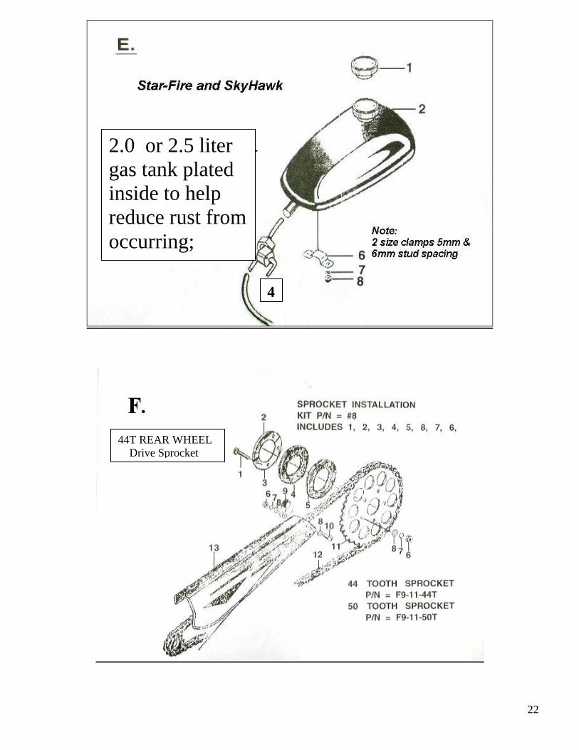
Fuel Tank installation A) Attach fuel petcock to tank. Use Teflon tape to seal threads. Careful not to strip threads.
B) Mount tank on bike top crossover frame with two supplied brackets and nuts.
C) Attach fuel line from tank to carburetor. Best to use USA made fuel line like GoodYear SAE 30-7
4.8mm obtained from local automotive stores like AutoZone. Factory supplied clear plastic line gets
hard over a period of time. *NOTE: Filters are contained in the petcock and in the carburetor inlet. If
engine runs poorly clean the valve filter as residue from the tank may have clogged it.. It is highly
recommend that a tank liner coating be applied inside the tank before installation. This product is called
Kreme and is available from motorcycle dealers;
D) Good idea to use a rubber strip to
cushion the tank on top tube.
IMPORTANT: PLEASE READ THIS:
Gas and Oil Mixture for Fuel ratio
The engine is a 2 cycle design, therefore, a gasoline/oil mixture is necessary. During the break-in period (1st
2 tanks of fuel ), the ratio is 16 parts gasoline to 1 part oil. After the break-in period, the ratio can increased
to 40 parts gasoline to 1 part oil. *NOTE: Synthetic 2 Stroke Oil can also be used to insure proper engine
lubrication. Consult your WD dealer for his recommendations for your country and area.
!WARNING! Remember safety first: Wipe up any spilled fuel. NEVER fuel a hot engine or
smoke while fueling. This could result in sudden fire, personal injury. Always move your motorized
bike at least 10 feet from any fueling area before attempting to start it. Never leave the tank fuel cap
off after fueling as rain water will contaminate the fuel and cause engine failure.
MAINTENANCE SECTION
# 1. How to Adjust Clutch if signs of slipping or squealing are encountered : A) Disengage clutch by pulling handle bar clutch lever inward and lock into catch lock.
B) Remove right side engine clutch cover and remove small locking screw on center *Clutch Adjust Nut.
C) Pull clutch arm on left rear engine inward. Back off *Clutch Adjust Nut ¼ turn counterclockwise.
D) Release clutch lever and check for slight clutch arm 1/16” free-play on opposite side of engine. Readjust
*Clutch Adjust Nut as required to get required 1/6” clutch arm free play.
E) Tighten *Clutch Adjust Nut on clutch plate clockwise until just snug.
F) Then re-install small locking screw in outer edge of *Clutch Adjust Nut .
G) Good idea to place a small gob of grease at gear mesh area. Use grease sparingly! Then replace cover.
H) Squirt light grade oil down clutch cable sheathing to reduce friction and make for easy lever pull.
*Clutch Adjust Nut
14
2. CarburetorPer instructions from the Dept. of EPA the idle and air fuel mixture screws have been epoxy sealed at the
factory to avoid end-user tampering. Depending on dusty riding conditions, clean air filter every 5 to 20
hours of operation by removing the filter cover to access the screen and element. Wash element with a
degreasing agent such as Simple Green™ or Purple Stuff™. Be sure element is completely dry before re-
assembly. IMPORTANT: If engine runs poorly clean tank shut off value filter.
MAINTENANCE SECTION Continued:
#3. 3 pt. Spark Plug Remove spark plug and inspect for excess carbon build up. Clean, re-gap to .0.036” of an inch if necessary.
Check plug after every 20 hours of operation. New spark plugs are available from your selling dealer. Be
careful using aftermarket spark plugs as heat range and threads differ greatly. An extra plug is included:
When replacing the spark plug in an Angle Fire head it’s best to use a 3 point electrode spark plug P/N
Z4JC to ensure total combustion. ( Ask your selling dealer for it by part number. )
#4. Exhaust system After 50 hours of operation check exhaust pipe for excessive oil and carbon build-up. If muffler is clogged
your dealer has replecements. Make sure attaching nuts are tight and no exhaust leaks are occurring. Be sure
to use supplied support strap to secure exhaust muffler to a solid anchor point on bike frame or engine.
A) To remove inside catalytic exhaust insert loosen the retaining screw on end cap and remove.
B) Pull cap and baffle out of pipe. Note: Some catalytic inserts are welded in and cannot be removed. If
you need a replacement muffler contact your dealer. 2010 models have an air shield welded on the
outside of muffler again per EPA rulings. This insures hot run so catalysis can clean the exhaust.
C) Clean with degreaser, rinse and dry. Re-assemble: File muffler attach flange to have smooth flat surface.
D) Always use a new exhasut gasket and good idea to use double nuts on muffler attach studs;
*NOTE: Excessive periods of low speed operation, idling or leaving fuel petcock in the “on” position during
shut down periods may cause the muffler to become clogged with unburned fuel.
#5. Drive Chain: 410 is standard and HD 415 is an option. Every time bike is ridden check the tension of the drive chain by:
A) Rolling to bicycle forward to remove slack from the bottom of the chain.
B) Find the center and push downward on the top of chain while measuring the deflection.
C) Tighten chain if deflection is more than ½ inch.
#6. Head Bolts Tighten all fasteners after each five hours of operation. Most important to check
Cylinder head bolts : Tighten in a X pattern to 10 ft/lb using a torque wrench. A two piece cylinder and
head design engine requires head bolts be kept tight. Important: Check head bolts before each and every
long ride, vibration can cause them to loosen and blow a head gasket. Caution: Do not over torque or head
bolts may break off. ( Twisted or broken head bolts due to over tightening is not covered by warranty. )
#7. Right side gears: Remove cover plate and keep small amount of heavy grease on gear train.
Do not over grease as leaks will occur and also may adversely affect clutch operation. Regular
greasing if required will help reduce gear wear and keep gear train quiet.
#8. Left side drive: Routinely pack grease in the shaft hole behind 10T sprocket and also in cover
bushing hole. This will also help deduce noise.
15
2010 EPA Certified sticker; Items, tools and extra service parts in tool kit; Typical Engine ID plates:
General Information
Obey all traffic regulations. Always wear a helmet while riding. Remember that you are riding a motorized
bicycle and other traffic may not be able to see you. Never operate your motorized bicycle on a pedestrian
through way or sidewalk while the engine is operating. Never operate your motorized bicycle in an unsafe
manner. Check local and state laws before riding on streets & wear a helmet.
ENGINE STARTING & OPERATION PROCEDURE
IMPORTANT: PLEASE READ THIS: Gas and Oil Mixture for Fuel ratio The engine is a 2 cycle design, therefore, a gasoline/oil mixture is necessary. During the break-in period (1
st
gallon of fuel), the ratio is 16 parts gasoline to 1 part 2 cycle oil. After the break-in period, the ratio is
increased to 40 parts gasoline to 1 part oil. The engine crankshaft bearings are lubricated from the oil in the
gas mix. A rich break in mixture ensures bearings will not cease. !WARNING! Remember safety first: Wipe up any spilled fuel. NEVER fuel a hot engine or light a cigarette while fueling. This could
result in sudden fire, personal injury. Always move your motorized bike at least 10 feet from any
fueling area before attempting to start it. Never leave the tank fuel cap off after fueling as rain water
will contaminate the fuel and cause engine failure.
Step #1. After filling tank with the correct oil/gas mix open the tank fuel valve. Fuel line is in the open
position when the small lever is pointed down. Move choke lever to the on position. This is the small lever
at the end of the choke cable All the way Up the choke is on. All the way Down the choke is off. Move
progressively downward to off position during engine warm up period.
Engine Starting procedure for Lever Clutch Models: 1. Pull the handlebar clutch lever inward, to disengage the engine from the rear wheel.
2. Pedal; (down hill if possible for first start)
3. A mid frame or rear wheel bike stand is helpful to start the engine in place.
4. Let out the clutch lever all the way out and continuing to pedal. The result is a direct engine hook up
via the friction clutch with the rear wheel via chain and sprocket. The engine will now start
spinning, Pedal until motor starts. Accelerate slowly at first..
5. Twist throttle to increase speed, reverse twist throttle to decrease speed. To stop,
disengage clutch and apply brakes. To accelerate, pedal and release clutch while
opening throttle.
6. Adjust choke to the smoothest engine running position.
7. After warm up push choke lever all the way down. If engine races too fast, or too slow,
pull clutch lever and lock in the notched catch, stop and adjust engine rpm.
8. If the rpm needs adjusting, turn the idle adjust screw (left side of carburetor) in or out
slowly to obtain the proper idle speed of about 1400 rpm +/- 100 rpm
To correctly break the engine in, Do not exceed 15 mph or 30 min. continual running
for the first 50 miles during engine brake in. Engine will develop more power after break in.
16
9. To stop the engine, push Kill switch and turn off gas valve at tank. Turning off the gas will prevent
fuel from being siphoned from tank. Warning Note: Never leave the tank gas valve in “open” position”
when engine is not running or the bike is in storage.
10. After or before each ride check all mounting fasteners, including hd. Bolts, axle and brakes.
11. Warning Note: Engine lock up or piston seizure due to improper gas / oil mixture will not be
covered by factory warranty. This the responsibility of the owner / operator to make sure the
gas and oil is mixed correctly.
YuanDong SkyHawk mfg. > ENGINE WARRANTY POLICY:
Proper use and maintenance is required for the continued enjoyment of your Bike Engine. This
product has been manufactured to strict quality control standards. For product warranty policy contact
your selling dealer. Warranty approval is subject to factory inspection and only the defective part or parts
will be replaced, not the complete kit or engine. Only the defective part or parts should be returned to the
selling dealer for warranty replacement consideration. Your dealer may require you to obtain his
authorization first before returning defective parts. Include description and picture of failure with as many
details as possible. Note: Seized pistons due to improper gas / oil mix or shipping damage due to carrier
neglect is not warranty.
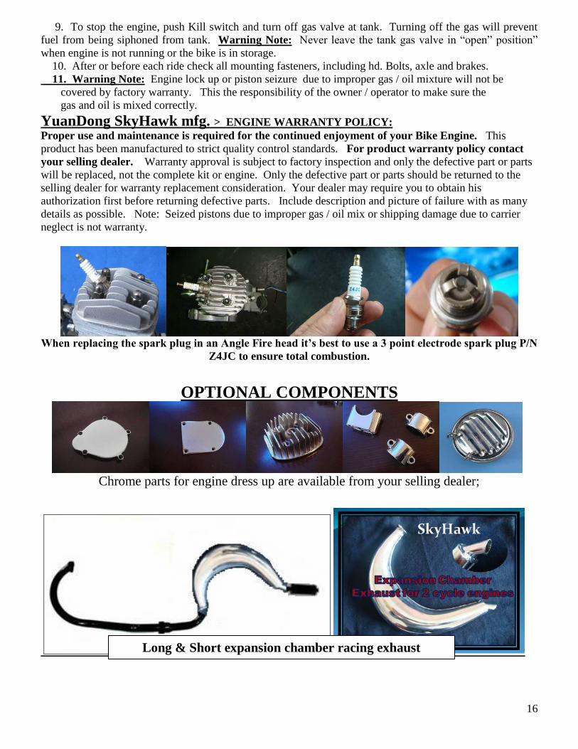
When replacing the spark plug in an Angle Fire head it’s best to use a 3 point electrode spark plug P/N
Z4JC to ensure total combustion.
OPTIONAL COMPONENTS
Chrome parts for engine dress up are available from your selling dealer;
Long & Short expansion chamber racing exhaust
17
Motorized Bike: > The ProShop Way:
GGG-2 engine has a centrifugal clutch on the right side and can be rope pulled or pedal started:
Improved catalytic muffler for 2010
EPA requirements with twice the size of
palladium insert plus an outside air shield;
Two psc. STREET POO POO PIPE
available in dealer service parts.
Wanna Pedal? Just pull 2 pins and you can pedal freely. Wanna Motor? Then just stick’em back in.
GGG-2 uses the standard
friction clutch as well as
having a centrifugal clutch.
18
Should you be lucky enough to find a dealer who has one of our GT2 special bikes made for
motorizing you can’t go wrong. These bikes have thicker frames along with GruBee HD axles with
hub mounted sprockets utilizing a 3 brake system and built in gas tank.
GT2A frames w/ rubber mt. are now available for WD distribution: