80
Magneti sm Separa te

MagnetismSeparate Physics

Magnetism facts
Name ______________________________
Class ______________________________
Teacher ______________________________
1) Like poles repel, unlike poles attract. 2) Contact forces need to touch to act, non-contact
forces do not. 3) Magnetism is a non-contact force. 4) A permanent magnet produces its own magnetic
field. 5) An induced magnet becomes a magnet in a magnetic
field.6) Iron, Nickel, Steel and Cobalt. 7) At the poles.
8) The strength reduces the further away you go.
9) A magnetic compass is made of a small bar magnet. It points towards geographic North, but magnetic South.
10) From North to South. 11) Place plotting compass near the magnet on a piece of
paper. Mark the direction the compass needle points. Move the plotting compass to many different positions in the magnetic field, marking the needle direction each time. Join the points to show the field lines.
12) A current flowing through it. 13) A solenoid. 14) Strong and uniform
15) A bar magnet16) Electromagnet can be turned off by a switch.
17) Increase the current, increase the number of turns on the coil, add an iron core.
18) The right hand rule. 19) Thumb – force/motion, First finger – field, second
finger – current 20) F = B × I × l21) A coil of wire carrying a current in a magnetic field
experiences a force that makes it rotate. A split ring commutator changes the current direction every half turn.
1) Like poles ______, unlike poles ________. 2) What is the difference between a contact
and a non-contact force?3) Is magnetism a contact/non-contact force?4) What is a permanent magnet?
5) What is an induced magnet?6) What are the four magnetic metals?7) Where is the field of a bar magnet
strongest?8) What happens to the strength of a magnetic
field the further away you go from a magnet?
9) What is a magnetic compass made of? What direction does it point?
10) What direction do magnetic field lines go in?11) How can we use a compass to plot the
pattern of the magnetic field lines around a magnet?
12) What causes a wire to produce a magnetic field?
13) What is the scientific name for a long coil of wire?
14) Describe the magnetic field inside a solenoid.
15) What kind of magnet has the same magnetic field as the long coil of wire?
16) What is the main advantage of using an electromagnet vs a permanent magnet?
17) Name three ways that we can make an electromagnet stronger.
18) What rule can we use to draw the magnetic of magnetic field pattern for a straight wire?
19) What do the fingers stand for in Fleming’s left hand rule?
20) What is the equation for the force on a current carrying wire?
21) How does an electric motor work?
Fold page here
1
2

Magnetism produces a non-contact force. This means that magnets do not need to touch for their to be a force. The force is carried by a force field.
Bar magnets have a north and a south pole. Like poles repel, unlike poles attract.
Magnets can also attract (but not repel) certain metals (iron, cobalt, nickel and steel but no others).
The region around a magnet where it has a magnetic effect is called its magnetic field.
When a magnetic material is placed in a magnetic field it will experience a force. The iron filings feel the effect of the magnetic field and show the direction of the forces in this region. Magnetic field lines flow from North to South.
The magnetic field is strongest where the field lines are closest together. The poles of a bar magnet have the strongest field. As you go further from the magnet, the field lines spread out. The magnetic field becomes weaker.
A permanent magnet produces its own magnetic field.
An induced magnet is a material that becomes a magnet when it is placed in a magnetic field.
Task: Complete in exercise book.
1
2
3
4
5
6
7
8
9
10
11
12
13
14
15
16
17
18
19
20
21
22
23
24
25

Basic
Q1. Magnetism is a contact/non-contact force.
Q2. What is the unit of a force?
Q3. Like poles__________, unlike poles __________
Q4. What are the three magnetic metals?
Q5. What is the name given to the type of magnet shown in the diagram to the right?
Q6. What are the lines on the diagram called?
Q7. Make the North and South poles on the diagram on the right by writing N and S on the correct ends of the magnet.
Medium
Q8. Answer true/false for the below questions:
a) Magnets need to touch for them to be a force between them.b) A North pole will repel a South pole. c) A North pole will attract a South pole. d) A South pole will attract a South pole. e) A South pole will attract a North pole.
Q9. Where is the magnetic field strongest by a bar magnet? Explain how we can tell this from the diagram above.
Q10. What is a permanent magnet?
Q11. What is an induced magnet?
Q12. Induced magnetism always causes a force of _______________.
Q13. What do you see when you sprinkle iron filings around a magnet?
Hard
Q14. Which one of the metal bars is a piece of unmagnetized iron? Explain why.
Q15. Sketch magnetic field lines for when:
a) Two North poles of bar magnets are near each other. b) Two South poles of bar magnets are near each other. c) A North and a South pole of two bar magnets are near
each other.
Q16. Explain some similarities and differences between:
a) Magnetism and gravity. b) Magnetism and electrostatic forces. c)
Task: Complete in exercise book.

Basic
Q1. non-contact
Q2. Newtons
Q3. Like poles repel, unlike poles attract.
Q4. Iron, nickel, cobolt
Q5. Bar
Q6. Magnetic Field Lines
Q7. Make the North and South poles on the diagram on the right by writing N and S on the correct ends of the magnet.
Medium
Q8. Answer true/false for the below questions:
a) Fb) Fc) Td) Fe) T.
Q9. The magnetic field is strongest at the poles. We show this by increasing the number of field lines per unit area ie. 5 lines in 1cm2 shows a magnetic field that is stronger than on showing 2 lines in 1cm2
Q10. A permanent magnet produces its own magnetic field
Q11. An induced magnet is a magnetic material that can be made into a magnet by placing it in a magnetic field
Q12. Induced magnetism always causes a force of attraction.
Q13. Magnetic Field
Hard
Q14. Bar 2 is unmagnetized iron, this is because there is only a force of attraction whereas bar 1 and 3 repel
Q15.
Q16. Explain some similarities and differences between:
d) Magnetism and gravity are both attractive forces, but magnets can repel other magnetse) Both magnetism and electrostatic forces cause attraction and repulsion, magnetic fields are caused
by moving electrons, whereas stationary electrons can cause electrostatic fields due to the a p.d.
N S

(a) Diagram 1 shows a magnetic closure box when open and shut. It is a box that stays shut, when it is closed, due to the force between two small magnets.
These boxes are often used for jewellery.
Diagram 1
Diagram 2 shows the two magnets. The poles of the magnets are on the longer faces.
Diagram 2
(i) Draw, on Diagram 2, the magnetic field pattern between the two facing poles.field pattern shows:
some straight lines in the gap(2)
(ii) The magnets in the magnetic closure box must not have two North poles facing each other.
Explain why.
north poles repel
(so) box will not close (2)
(b) A student is investigating how the force of attraction between two bar magnets depends on their separation.
She uses the apparatus shown in Diagram 3.
Diagram 3
1

She uses the following procedure:
• ensures that the newtonmeter does not have a zero error
• holds one of the magnets
• puts sheets of paper on top of the magnet
• places the other magnet, with the newtonmeter magnetically attached, close to the first magnet
• pulls the magnets apart
• notes the reading on the newtonmeter as the magnets separate
• repeats with different numbers of sheets of paper between the magnets.
The results are shown in the table.
Number of sheetsof paper between themagnets
10 20 30 40 50 60 70 80 120
Newtonmeter readingas the magnetsseparate
3.1 2.6 2.1 1.5 1.1 1.1 1.1 1.1 1.1
(i) Describe the pattern of her results.
as paper increases (rapid) decrease in force needed
force levels off (after 50 sheets) (2)
(ii) No matter how many sheets of paper the student puts between the magnets, the force shown on the newtonmeter never reaches zero.
1
2

Why?the newtonmeter will show the weight of the top magnet (1)
(iii) The student is unable to experiment with fewer than 10 sheets of paper without glueing the magnet to the newtonmeter.
Suggest why.
(top) magnet and newtonmeter separate before magnets separateaccept reverse argument
(because) force between magnets is greater than force between magnet and hook of newtonmeter
(2)
(iv) Suggest three improvements to the procedure that would allow the student to gain more accurate results.
any three from:
• means of reading value of force at instant the magnets are pulled apart• increase the pulling force gently
oruse a mechanical device to apply the pulling force
• clamp the bottom magnet• use smaller sheets of paper• fewer sheets of papers between readings (smaller intervals)• ensure magnets remain vertical• ensure ends of magnet completely overlap• repeat the procedure several times for each number of sheets and take
a mean• make sure all sheets of paper are the same thickness
(3)
(v) The thickness of one sheet of paper is 0.1 mm.
What is the separation of the magnets when the force required to separate them is 2.1 N?
3 (mm)30 × 0.1 ecf gains 2 marks2.1 N corresponds to 30 sheets gains 1 mark
Separation of magnets = ________________ mm(3)
(Total 15 marks)
123
45
6
789
101112131415161718
192021

A compass contains a small bar magnet. It always points towards the south pole of a magnet.The Earth has a magnetic field caused by molten (liquid) iron in the Earth’s outer core.
The Earth is like a big bar magnet. The north pole of the Earth is actually magnetic south. Compasses point towards geographic north but that is magnetic south.
To plot the magnetic field around a magnet:
• Place magnet on a sheet of (plain) paper.
• Place the compass near the end of the magnet.
• Mark the position that the compass needle points to.
• Move the compass so the opposite end is at this position and mark the new position where the compass tip settles.
• Repeat above and below the magnet and then connect the marks together to construct a field line.
Practical: Plot the Earth’s magnetic field. Use the plotting compasses and a magnet. Remember that magnetic south is geographic north.
Compasses1
2
3
4
5
6
7
8
9
10
11
12
13
14
15
16
17
18
19
20
21
22

Task: Complete in exercise book.
Basic

Q1. Does a compass point towards the North pole or the South pole of a magnet?
Q2. On the diagram, draw an arrow in each circle to show which way the compass is points.
Medium
Q3. Earth’s North pole is actually magnetic ______________.
Q4. What evidence do we have the Earth’s core is magnetic.
Q5. Using the diagram to the left, draw a complete diagram of the Earth’s magnetic field.
Q6. What is a compass made of?
Q7. Describe the process of plotting a magnetic field diagram using a compass.
Hard
Q8. Explain why a compass isn’t useful if you have something producing a magnetic field nearby (e.g. a credit card or a mobile phone).
Q9. Donal is hiking, but he is a bit lost. He knows that he’s standing on top of Mount Blodwyn, but he doesn’t know which way he is facing. Looking straight ahead, he can see a lake. The pictures below show Donal’s map and compass.
a) What is Donal’s compass lined up with?b) Explain why Donal can use his map and compass to figure out which direction he is looking in. c) Which lake is Donal looking at?
Task: Complete in exercise book.
Basic
Q1. A compass is a tiny bar magnet, so the north seeking pole of the magnet will seek south. The Earth has a South Magnetic pole which is marked up as Geographically North (just to confuse you)

Q2. On the diagram, draw an arrow in each circle to show which way the compass is points.
Medium
Q3. Earth’s North pole is actually magnetic south.
Q4. The North of a suspended bar magnet will seek magnetic south
Q5. Using the diagram to the left, draw a complete diagram of the Earth’s magnetic field.
Q6. Permanent magnet
Q7. Describe the process of plotting a magnetic field diagram using a compass.
Hard
Q8. The bar magnet that makes up the compass will move to a ‘false’ north produced by the object creating the magnetic field, which will cause the reader to believe North is in a different direction
Q9. Donal is hiking, but he is a bit lost. He knows that he’s standing on top of Mount Blodwyn, but he doesn’t know which way he is facing. Looking straight ahead, he can see a lake. The pictures below show Donal’s map and compass.
a) Northb) Place compass on the map. Move map around under compass until the ‘Magnetic North’ matches
Geographical North on the mapc) Lake Barry
Any current flowing through a wire creates a magnetic field. This is called an electro-
Making an electromagnet practical
1
2

magnet.
We can use the right hand rule to show the direction of this magnetic field. Your thumb gives the direction of the current and your fingers give the
direction of the field lines. To increase the strength of an electro-magnet:
• Wind the wire so it has more turns.
• Increase the current in the wire.
• Add an “iron core” to the centre of the loops of wire.
Task: Label diagram and write prediction
Task:
What is the independent variable?
Number of coils
Number of paperclips
5 2
10 4
15 7
20 9
25 12
30 14
35 16
40 18
1
2
3
4
5
6
7
8
9

What is the dependent variable?
After you’ve taken results:
Plot a graph of number of paperclips (on the y axis) against the number of coils (on the x axis). Remember to write a title.
Stretch: Draw a line of best fit and calculate the gradient.
Q1.Figure 1 shows two paper clips hanging from a bar magnet.
Figure 1
The paper clips have become magnetised.
(a) Label the north and south poles of both paper clips.
top of each paper clip labelled N / northboth parts required
andbottom of each paper clip labelled S / south
(1)
A student investigated how the number of turns of wire on an electromagnet affects the
12
34

strength of the electromagnet.
Figure 2 shows the equipment used by the student. Throughout the investigation the student kept the current through the wire constant.
Figure 2
(b) The student measured the strength of the electromagnet by counting the number of paper clips the electromagnet could hold.
Explain why it was important that the paper clips were all the same size.
so the paper clips have the same weight / mass1
which allows the results for different numbers of turns to be compared (fairly)allow fair testallow the control variable (is the weight / mass of a paper clip)allow to obtain valid resultsignore accurate results
(2)
The table below shows the student’s results.
Number of turns of wire on the electromagnet
Number of paper clips held
10 3
20 6
30 9
40 12
(c) Describe the pattern shown in the table.
12
34567

as the number of turns increases so does the number of paper clips (held)allow positive correlation
in a linear patterndirectly proportional scores 2 marksallow a correct description of directly proportional for 2 marks
(2)
(d) The student then used 50 turns of wire on the electromagnet.
The electromagnet picked up 18 paper clips. This was more paper clips than the student had expected.
Which one is the most likely cause of this result?
Tick one box.
The paper clips used with 50 turns were larger than the others.
There were less than 50 turns of wire on the electromagnet.
Some of the paper clips were already magnetised.
(1)
(e) The student repeated the measurement for 50 turns of wire three more times.
This gave her the following set of results.
18 16 14 15
Explain what the student should now do with the four results for 50 turns of wire.
discount the result of 18ignore repeat experiment / measurements
1
as the three new results are similar (and not close to 18)1
and use 15 (the mean of the new results)allow find the mean of the remaining results (16,14 and 15)if no other marks have been awarded: calculate the mean (of all four results) (1)round down to 15 (1) − this mark only scores if the mean of 15.75 has been calculated
(3)
(f) The student wrote the hypothesis:
12
345
678
910
111213141516

‘Increasing the current through the wire will make the electromagnet stronger.’
Describe how the student should change the investigation to test this hypothesis.
keep number of turns constantallow a specific number of turns
1
(use the variable resistor to) change the current (several times)change the p.d. is insufficient
1
(for each current value) count how many paper clips the electromagnet will hold (3)
(Total 12 marks)
A current flowing through a wire produces a magnetic field.
This effect can be increased by having a coil of wire (called a solenoid).
A solenoid creates a field like a bar magnet.
The field is strongest inside the solenoid.
You can also use the right hand grip rule for a solenoid. This time your thumb gives the direction of
Solenoid & uses of electromagnets
123
456
7
8
9
10
11
12
13
14
15
16
17
18

the magnetic field lines and your curled fingers give the direction of the current.
The task on the following page guides you through how electromagnets help some common devices to work. Main points to remember:
1. A current flowing causes a magnetic field. 2. This magnetic field can then attract an object made of iron, nickel or
cobalt. 3. Making the object move.
Basic:
1. What causes a wire to produce a magnetic field?
2. What kind of magnet has the same magnetic field as the long coil of wire?
3. What is the scientific name for a long coil of wire?4. What is the main advantage of using an electromagnet vs a permanent magnet?5. Why would steel be bad to use as the core of an electromagnet?6. Name a metal that would be more suitable to use as the core of an electromagnet.7. Suggest two other ways of increasing the strength of an electromagnet.
Medium: Describe how some electromagnetic devices work
8. An electric bell:
When the push switch is closed the current flows through the ___________. The electromagnet then attracts the iron ______. The hammer moves and strikes the _________. As this happens the contacts separate and the circuit is broken. The electromagnet is switched ______ and the hammer springs back.
9. Sorting scrap metal:
In a scrap yard electromagnets can be used to separate iron and ________ objects from other materials. A thick __________ supplies current to the electromagnet. The current is switched on to pick the metals up and then switched _____ to put them down.
1
2
3
4
5
6
7

10. Electromagnetic switches – relays.
Sometimes it is dangerous to switch on a circuit directly. For example, a car starting motor needs a current of over 100 amps. An electromagnetic switch called a _________ can be used to switch the circuit on safely. When the switch in the _________ circuit is closed the magnet is switched on. This pulls the iron __________ towards it and the ____________ are closed. The motor in the circuit is now switched on.
Hard:
11. Explain how a relay similar to one in the diagram above could be used to turn an electric motor off.
12. Explain how you could use a plotting compass to draw the direction of magnetic field lines around an electromagnet?
13. A student gives a steel ball bearing a gentle push in the direction of the iron rod. At the same time the student closes the switch S. Explain the effect on the motion of the ball bearing when the switch S is closed.
14. Using the equipment shown to the left, describe how students could build an electromagnet. Include in your answer how the students should vary and test the strength of their electromagnet (6).
Basic:
1. A flowing current/moving electrons? 2. Bar magnet has same magnetic field as
solenoid/long coil of wire?3. A long coil of wire is called a solenoid4. An electromagnet can be turned on/off, in addition you can vary its strength?5. Steel would continue to be magnetised and the electromagnet would not turn on/off6. A more suitable metal would be ‘soft iron’ or flat sheets of iron stuck together to for a laminate.7. Two other ways of increasing the strength of an electromagnet would be to
increase current flowing, or number of coils
Medium: Describe how some electromagnetic devices work
8. An electric bell:
When the push switch is closed the current flows through the COIL. The electromagnet then attracts the iron ARM. The hammer moves and strikes the GONG. As this happens the contacts separate and the circuit is broken. The electromagnet is switched OFF and the hammer springs back.
9. Sorting scrap metal:
In a scrap yard electromagnets can be used to separate iron and STEEL objects from other materials. A thick CABLE supplies current to the electromagnet. The current is switched on to pick the metals up and then switched OFF to put them down.
10. Electromagnetic switches – relays.

Sometimes it is dangerous to switch on a circuit directly. For example, a car starting motor needs a current of over 100 amps. An electromagnetic switch called a RELAY can be used to switch the circuit on safely. When the switch in the INPUT circuit is closed the magnet is switched on. This pulls the iron LEVER towards it and the CONTACTS are closed. The motor in the circuit is now switched on.
Hard:
11. SEE ABOVE. 12. SEE p9
13. The ball moves slowly at first. As the switch is closed, current flows in the coil and a magnetic field is set up around the electromagnet. The ball will be attracted to the electromagnet, and will accelerate at an increasing rate towards the electromagnet until it is next to it
14. 1. Wrap 5 turns of insuated wire around the iron nail. 2. Suspend the iron nail and insulated wire (electromagnet) from wooden clamp and stand. 3. Attach insulated wire to connecting leads, and connecting leads to power supply. 4. Set Power
Supply to 4v, and hold steel paper clips under electromagnet. 5. Count how many paper clips the electromagnet holds up, and record. 6. Wrap another 5 turns of insulated wire around the iron nail and repeat steps 2-6, until you have wrapped 35-40 turns.
Q1.The diagram shows an electromagnet used in a door lock.
(a) The push switch is closed and the door unlocks. Explain in detail how this happens.Push switch closes and complete circuit is made, current flows through the coil making an electromagnet (1), with a magnetic field around itIron bolt is attracted to the electromagnet and moves towards it, to the left (1) Iron bolt moves out door, and the door is unlocked (1)
3 marks
(b) The switch is released and the door locks. Explain in detail how this happens.Push switch is no longer closed and the circuit is no longer complete, no current flows, and the electromagnet is no longer magnetic/has a magnetic field around it (1), Iron bolt no longer attracted and spring pushes bolt back into the door (1)
2 marksMaximum 5 marks
1234
567

Q2.Figure 1 shows a straight wire passing through a piece of card.
A current (I) is passing down through the wire.
Figure 1
(a) Describe how you could show that a magnetic field has been produced around the wire. (2)
move a (magnetic / plotting) compass around the wire1
the changing direction of the compass needle shows a magnetic field has been produced
OR
sprinkle iron filings onto the card (1)
tapping the card will move the filings to show the magnetic field (pattern) (1)
(b) Figure 2 shows the ignition circuit used to switch the starter motor in a car on.
The circuit includes an electromagnetic switch.
Figure 2
Explain how the ignition circuit works. (4)
Level 2 (3–4 marks):A detailed and coherent explanation is provided. The response makes logical links between clearly identified, relevant points that explain how the ignition circuit works.
Level 1 (1–2 marks):Simple statements are made. The response may fail to make logical links between the
12
3
4
5
6
789
1011

points raised.
0 marks:No relevant content.
Indicative content (some points should be included)• closing the (ignition) switch causes a current to pass through the electromagnet• the iron core (of the electromagnet) becomes magnetised• the electromagnet / iron core attracts the (short side of the ) iron arm• the iron arm pushes the (starter motor) contacts (inside the electromagnetic switch)
together• the starter motor circuit is complete• a current flows through the starter motor (which then turns)
A current carrying wire at right angles to a magnetic field experience the following force:
Force = magnetic flux density × current × length of wire in field
F = B × I × L
Where:
The force, F, in measured in Newtons (N)
The magnetic flux density, B, is measured in Tesla (T)
Current, I, is measured in Amps (A)
Length, L, is measured in metres (m).
This is known as the motor effect.
Three ways that the force can be increased:
1) Increase current.
Force on a current carrying wire
1
23
456789
101112131415161718
19
20
21
22
23
24
25
26
27
28
29
30
31
32

2) Increase magnetic flux density.
3) Increase length of wire in magnetic field.
The force is zero if the current goes in same direction as magnetic field.
This effect can be investigated by:
1. Having a permanent magnet on a balance.
2. Changing the current in the circuit by changing resistance of rheostat.
3. Measuring the change in mass recorded on the balance.
Task: Complete in exercise book.
F = B × I × l
Basic
1. Give the symbol and unit for:a) Magnetic flux densityb) Currentc) Length
2. Calculate the force on the following current carrying wires:a) B = 0.2 T, I = 5 A, l = 2 m b) B = 0.01 T, I = 0.02 A, l = 0.5 m c) B = 0.3 T, I = 2 A, l = 1.2 m d) B = 0.005 T, I = 0.2 A, l = 0.015 m e) B = 4 T, I = 13 A, l = 0.8 m
3. Using the numbers in the diagram opposite, calculate the force exerted on the wire.
Medium: Wordy questions that you need to rearrange the formula for.
4. Rearrange the equation to give equations for the magnetic flux density, current and length of wire. 5. Calculate the current on a wire that has length 0.2m, a force on it of 1.2 N and is in a magnetic field
of flux density 0.12T. 6. Calculate the length of a wire that has a current of 0.5A flowing through it, has a force of 14 N on it
and is in a magnetic field of flux density 0.04T. 7. Calculate the magnetic flux density that a wire of length 1.6m, that has a current of 13A flowing
through it and has a force of 0.8N exerted on it. 8. Calculate the current on a wire that has length 0.25m, a force on it of 0.2 N and is in a magnetic
field of flux density 0.03T.
1
2
3
4
5
6
7
8
9
10
11
12

Hard: Unit conversions and a tricky multi-step calculation to finish.
9. Calculate the magnetic flux density that a wire of length 12 cm, that has a current of 13A flowing through it and has a force of 0.8N exerted on it.
10. What is the current in a 4.00m wire at right angles to the field lines of a magnetic flux of magnetic flux density 300 mT, which experiences a force of 15.3 N.
11. How long is a conductor that carries a current of 0.200A at right angles to a magnetic field with a magnetic flux density of 120mT, and which experiences a force of 1.20N?
12. A horizontal straight wire of length 0.30m carries a current of 1.5A perpendicular to a horizontal uniform magnetic field of flux density 5.0 × 10-
2 T. The wire “floats” in equilibrium in the field. What is the mass of the wire?
13. A conductor has a resistance of 200 Ω, and there is a potential difference of 12V across the conductor. There is a force of 5 N on the conductor, and it is of length 5cm. What is the magnetic flux density that the conductor is in?
Task: Complete in exercise book.
F = B × I × l
Basic
1. Give the symbol and unit for:a) Magnetic flux density; T, teslab) Current: I, Ampsc) Length, L, metres
2. Calculate the force on the following current carrying wires:a) 2Nb) 0.1mNc) 0.72Nd) 15µNe) 41.6N
3. 75mN
Medium: Wordy questions that you need to rearrange the formula for.
4. Rearrange the equation to give equations for the magnetic flux density, current and length of wire. 5. Calculate the current on a wire that has length 0.2m, a force on it of 1.2 N and is in a magnetic field
of flux density 0.12T. 50A 6. Calculate the length of a wire that has a current of 0.5A flowing through it, has a force of 14 N on it
and is in a magnetic field of flux density 0.04T. 700m7. Calculate the magnetic flux density that a wire of length 1.6m, that has a current of 13A flowing
through it and has a force of 0.8N exerted on it. 0.038T8. Calculate the current on a wire that has length 0.25m, a force on it of 0.2 N and is in a magnetic
field of flux density 0.03T. 26.6A
Hard: Unit conversions and a tricky multi-step calculation to finish.
mT → T ÷ 1,000
cm → m ÷ 100

9. Calculate the magnetic flux density that a wire of length 12 cm, that has a current of 13A flowing through it and has a force of 0.8N exerted on it. 0.51T
10. What is the current in a 4.00m wire at right angles to the field lines of a magnetic flux of magnetic flux density 300 mT, which experiences a force of 15.3 N. 12.5A
11. How long is a conductor that carries a current of 0.200A at right angles to a magnetic field with a magnetic flux density of 120mT, and which experiences a force of 1.20N? 50m
12. A horizontal straight wire of length 0.30m carries a current of 1.5A perpendicular to a horizontal uniform magnetic field of flux density 5.0 × 10-
2 T. The wire “floats” in equilibrium in the field. What is the mass of the wire? 2.3g
13. A conductor has a resistance of 200 Ω, and there is a potential difference of 12V across the conductor. There is a force of 5 N on the conductor, and it is of length 5cm. What is the magnetic flux density that the conductor is in? 1667T
Task: Plot a graph of Force (N) against Current (A).
Stretch: Fit a straight line and calculate the gradient.
Super stretch: The length of the wire is 0.2m. How could we get the magnetic flux density from the gradient?
mT → T ÷ 1,000
cm → m ÷ 100
Gradient of this graph gives Force/current.
Since l =0.2m and remains constant, then
Graph gradient is Force/current x length
From F=BIl, B=F/Il
And B will be a tenth of the calculated gradient
Current (A)
Force (N)
0 0.0
1 3.0
2 7.5
3 11.7
4 16.0
5 20.5
6 29.9
7 33.5
8 37.7
1

Q1 (a) A laboratory technician sets up a demonstration.
A flexible wire is suspended between the ends of a horseshoe magnet. The flexible wire hangs from a cotton thread. When the switch is closed, the wire kicks forward.
Identify the effect which is being demonstrated. (1)
Motor
(b) A teacher makes some changes to the set-up of the demonstration.
What effect, if any, will each of the following changes have?
(i) more powerful horseshoe magnet is used. (1)
increase the strength of the magnetic field
(ii) The connections to the power supply are reversed. (1)
1

Wire will move in opposite direction
Q2. (a) A science technician sets up the apparatus shown below to demonstrate the motor effect. He uses a powerful permanent magnet.
The copper roller is placed across the metal rails. When the switch is closed, the copper roller moves to the right.
(i) Complete the sentence by drawing a ring around the correct line in the box.
an electrical conductor.
This happens because copper is an electrical insulator.
a magnetic material.
(1)
(ii) Suggest one change that the technician can make which will cause the copper roller to move faster. (1)
increase current1

accept increase p.d. / voltageoruse stronger magnets
accept move magnets closerdo not accept use larger magnets
(iii) Suggest two changes which the technician can make, each of which will separately cause the copper roller to move to the left. (2)
reverse the poles / ends (of the magnet)either order
1
reverse the connections (to the power supply)
(b) Many electrical appliances, such as vacuum cleaners, drills and CD players, contain electric motors. As more electrical appliances are developed, more electricity needs to be generated. Generating electricity often produces pollutant gases.
(i) Complete the sentence by drawing a ring around the correct line in the box.
Generating more electricity to power the increasing number of electrical
an ethical
appliances used raises an environmental issue.
a political
(1)
(ii) The number of electrical appliances used in the world’s richest countries is increasing yet many people in the world’s poorest countries have no access to electricity.
What type of issue does this inequality between people in different countries raise?
ethicalallow political (instability)allow economic (migration)
(1)
12345
678
9
10
11
12
13
14
15
161718

The direction of the force acting on a current carrying wire can be predicted using Fleming’s left-hand rule. We can remember which finger is which by using the following acronym:
FBI!
Modelled example:
In the example to the right, the magnetic field lines are going from left to right. Therefore our first finger will go from left to right.
The current is coming towards us and so our second finger should point towards you.
The thumb now gives the direction of the force on the wire.
Your thumb should be pointing upwards and so the force on the wire is upwards.
Remember:
1. Magnetic field lines flow from North to South.2. Current flows from positive to negative.
Fleming’s left hand rule
1
2
3
4
5
6
7
8
9
10
11
12
13
14
15
16
17
18
19

The longer line in the symbol of a cell/battery shows the positive end of the cell/battery.
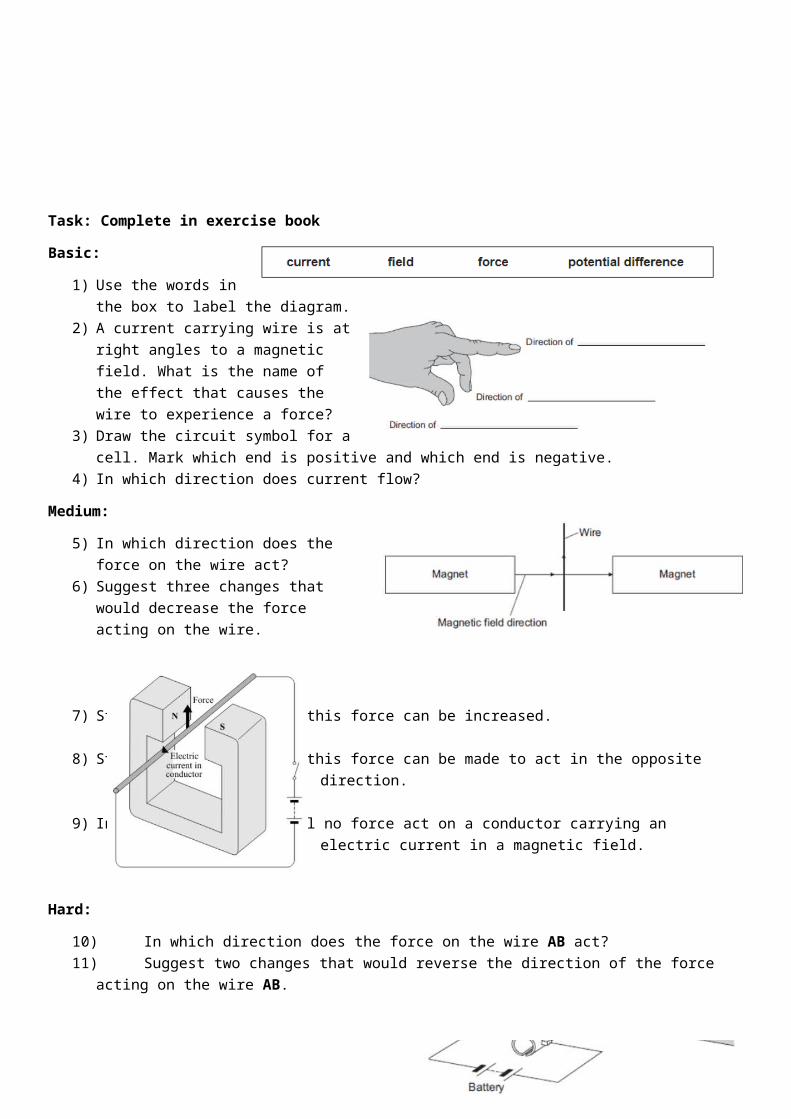
Task: Complete in exercise book
Basic:
1) Use the words in the box to label the diagram.
2) A current carrying wire is at right angles to a magnetic field. What is the name of the effect that causes the wire to experience a force?
3) Draw the circuit symbol for a cell. Mark which end is positive and which end is negative.
4) In which direction does current flow?
Medium:
5) In which direction does the force on the wire act?
6) Suggest three changes that would decrease the force acting on the wire.
7) State two ways in which this force can be increased.
8) State two ways in which this force can be made to act in the opposite direction.
9) In what circumstance will no force act on a conductor carrying an electric current in a magnetic field.
Hard:
10) In which direction does the force on the wire AB act? 11) Suggest two changes that would reverse the direction of the force acting on the wire AB.
1
2

12) Closing the switch creates a force that acts on the wire XY. Explain why a force acts on the wire XY when the switch is closed.
13) The force causes the wire XY to move. In what direction does the wire XY move?
14) The student replaced the battery with a low frequency alternating current (AC) power supply. The student closed the switch. Describe the movement of the wire & explain why the wire moves this way.
Task: Complete in exercise book
Basic:
1) Use the words in the box to label the diagram.
2) A current carrying wire is at right angles to a magnetic field. What is the name of the effect that causes the wire to experience a force? Motor effect
3) Draw the circuit symbol for a cell. Mark which end is positive and which end is negative.
4) In which direction does current flow? Conventional current flow is positive to negative
Medium:
5) In which direction does the force on the wire act? Downward (into paper)
6) Suggest three changes that would decrease the force acting on the wire. decrease: current flowing, strength of magnetic field, length of wire in magnetic field
7) State two ways in which this force can be increased. Increase: current flowing, strength of magnetic field, length of wire in magnetic field8) State two ways in which this force can be made to act in the opposite direction. Reverse direction of current flowing, or reverse direction of magnetic field9) In what circumstance will no force act on a conductor carrying an electric current in a magnetic field.
Hard:
10) In which direction does the force on the wire AB act? Downward11) Suggest two changes that would reverse the direction of the force acting on the wire AB. Reverse direction of current flowing, or reverse direction of magnetic field
12) Closing the switch creates a force that acts on the wire XY. Explain why a force acts on the wire XY when the switch is closed. Switch closes and a complete circuit is made, current flows, and this causes a magnetic field perpendicular to wire to be set up. The direction of the magnetic field is dependent on current flow, and using the right hand grip rule it is anti-clockwise (looking in from Y). This magnetic

field adds/subtracts to the magnetic flux density of the magnetic field caused by the magnets. In this case the fields add to create a more dense field under the wire and subtract to create a less dense field above the wire. The wire will therefore move upwards.
13) The force causes the wire XY to move. In what direction does the wire XY move? Upwards14) The student replaced the battery with a low frequency alternating current (AC) power supply. The student
closed the switch. Describe the movement of the wire & explain why the wire moves this way. It will move/oscillate up/down since an alternating current changes direction
(a) Some people wear magnetic bracelets to relieve pain.
Figure 1 shows a magnetic bracelet.
There are magnetic poles at both A and B.Part of the magnetic field pattern between A and B is shown.
Figure 1
What is the pole at A? North
What is the pole at B? North(1)
(b) Figure 2 shows two of the lines of the magnetic field pattern of a current-carrying wire.
Figure 2
The direction of the current is reversed.
What happens to the direction of the lines in the magnetic field pattern?
change direction/reverse(1)
(c) Fleming’s left-hand rule can be used to identify the direction of a force acting on a current-carrying wire in a magnetic field.
(i) Complete the labels in Figure 3.
Figure 3

(2)
(ii) Figure 4 shows:
• the direction of the magnetic field between a pair of magnets
• the direction of the current in a wire in the magnetic field.
Figure 4
In which direction does the force on the wire act?
Into paper(1)
(iii) Suggest three changes that would decrease the force acting on the wire.
1. less current
2. weaker magnetic field
3. rotate magnets so the wire is not perpendicular to direction of magnetic field(3)

(d) Figure 5 shows part of a moving-coil ammeter as drawn by a student.
The ammeter consists of a coil placed in a uniform magnetic field.When there is a current in the coil, the force acting on the coil causes the coil to rotate and the pointer moves across the scale.
Figure 5
(i) The equipment has not been set up correctly.
What change would make it work?reverse one of the magnets (1)
(ii) Figure 6 shows the pointer in an ammeter when there is no current.
Figure 6
What type of error does the ammeter have?systematic or zero error (1)
(Total 10 marks)

A DC motor is made out of a coil of wire within a magnetic field.
When a current flows through the coil this creates a magnetic field.
This magnetic field interacts with the permanent magnetic field in the motor, causing a force.
There is an equal and opposite force on each side of the coil. This is because the current on each side of the coil is flowing in opposite directions.
This force causes the motor to rotate. However, when the coil has rotated 180 degrees, the current are now flowing in opposite directions to before.
This means that the coil would experience a force in the opposite direction.
To prevent this, a split ring commutator changes the direction of every half turn. This is due to two halves of the coil swapping from one carbon brush to another.
This allows for the motor to experience a force in the same direction. The commutator disconnects the current every half turn, but momentum keeps the motor rotating.
To make the motor spin in the opposite direction, we can:
1. Reverse the direction of current. 2. Reverse the direction of the magnetic field lines
To make the motor spin faster, we can:
1. Increase the current. 2. Increase the magnetic flux density. 3. Increase the number of turns in the coil.
DC Motors1
2
3
4
5
6
7
8
9
10
11
12
13
14
15
16
17
18
19
20
21
22
23
24
25
26
27
28

Task: Complete in exercise book.
Basic
The diagram shows a simple electric motor. The following statements explain how the motor creates a turning force. The statements are in the wrong order.
Q1. Arrange the statements in the correct order. Two of them have been done for you.
Q2. Why do the opposite sides of the coil in a dc motor feel forces in opposite directions?
Q3. In what direction will the motor spin?
Medium
Q4. What does a split ring commutator do?
Q5. In a dc motor, the commutator disconnects the current every half turn. Why doesn’t the motor stop?
Q6. The electric motor produces a turning force. Give two ways of increasing the turning force.
Q7. Suggest two changes to the electric motor, each one of which would make the coil spin in the opposite direction.
Q8. When there is a current in the coil, the coil rotates continuously. Explain why.
Q9. The battery has been used for a long time and the potential difference across it has decreased from 3V to 2V. What effect does this have on the turning force of the electric motor? Explain your answer.
Hard
Q10. The diagram to the left shows an electric motor, without a split ring commutator. What is the purpose of a split ring commutator?
Q11. The arrows labelled F show the direction of the forces acting on the sides of the coil. Describe the motion of the coil until it comes to rest.
Q12. A resistor is placed in series with the battery and coil. What effect, if any, does this have on the force F? Explain why.
Q13. Most electric motors use electromagnets instead of permanent magnets. State three of the features of an electromagnet which control the strength of the magnetic field obtained.
Task: Complete in exercise book.
Basic
The diagram shows a simple electric motor. The following statements explain how the motor creates a turning force. The statements are in the wrong order.
4
3
1
5
2

Q1. Arrange the statements in the correct order. Two of them have been done for you.
Q2. Why do the opposite sides of the coil in a dc motor feel forces in opposite directions? The current is in the opposite direction
Q3. In what direction will the motor spin? Magnetic field is ‘left to right’, current is flowing into paper, left side moves down therefore the motor will spin anti-clockwise
Medium
Q4. What does a split ring commutator do? changes direction of current flowing through wire
Q5. In a dc motor, the commutator disconnects the current every half turn. Why doesn’t the motor stop? Momentum causes the coil to continue spinning
Q6. The electric motor produces a turning force. Give two ways of increasing the turning force. Increase; strength of magnetic field, current flowing (by increasing pd)
Q7. Suggest two changes to the electric motor, each one of which would make the coil spin in the opposite direction. Reverse polarity of supply (batteries), or change direction og magnetic field)
Q8. When there is a current in the coil, the coil rotates continuously. Explain why. A flowing current will cause a magnetic field to be established which will interact with the magnetic field caused by the magnets. This causes a force to act on the wire which due to the direction of current flowing in the wire will cause one side of the coil to move downwards and the other upwards. The split ring commutator changes the direction of the current through the wire as it spins, so the force acting in that side of the coil is always in the same direction. The momentum the coil has, will keep the coil spinning as the split ring commutator disconnects and reconnects.
Q9. The battery has been used for a long time and the potential difference across it has decreased from 3V to 2V. What effect does this have on the turning force of the electric motor? Explain your answer. Less pd, so less current, therefore the size and density of magnetic field around the wire will be decreased. Therefore the force acting on the coils will decrease and the coil will not spin as quick
Hard
Q10. The diagram to the left shows an electric motor, without a split ring commutator. What is the purpose of a split ring commutator? Changes the direction of the current flowing in each side of the coil
Q11. The arrows labelled F show the direction of the forces acting on the sides of the coil. Describe the motion of the coil until it comes to rest. The left side of the coil will move upwards in a clockwise direction, but as it moves through its apex and starts to move down through right hand side, the force generated by the interacting magnetic fields will cause the coil to move in an anti-clockwise direction. As it moves back into the left side the coil will experience a force causing it move in a clockwise direction. The coil will continue to oscillate backwards and forwards until it comes to rest perpendicular to the magnetic field between the magnets.
Q12. A resistor is placed in series with the battery and coil. What effect, if any, does this have on the force F? Explain why. The resistor is a current limiter, so less current will flow leading to a smaller magnetic field. This will result in a smaller being generated.

Q13. Most electric motors use electromagnets instead of permanent magnets. State three of the features of an electromagnet which control the strength of the magnetic field obtained. Can control the pd across the coils in the electromagnetic, so you have control over the current flowing and size and strength of magnetic field. The core used will also determine the strength of magnetic field. The number of coils can be controlled which will determine size and strength of mag. Field.
The diagram shows a ‘G-machine’. The G-machine is used in astronaut training.
The G-machine moves the astronaut in a horizontal circle.
(a) The force causing the astronaut to move in a circle is measured.
The graph shows how the speed of the astronaut affects the force causing the astronaut to move in a circle for two different G-machines.
The radius of rotation of the astronaut is different for each G-machine.

Speed in metres per second
(i) State three conclusions that can be made from the graph. (3) the greater the speed (of a centrifuge), the greater the force
answers must be comparativeaccept velocity for speedaccept positive correlation between speed and forcespeed and force are not proportional – treat as neutral
the smaller the radius, the greater the force (at a given speed)allow (G machine) 1 has / produces a greater force (thanG machine 2 ) at the same speedmust be comparative, eg a small radius produces a large force = 0 marks on own
as the speed increases the rate of change in force increasesaccept force is proportional to the square of the speedordoubling speed, quadruples the forceaccept any clearly correct conclusion
(ii) The speed of rotation of G-machine 1 is increased from 20 m/s to 40 m/s.
Determine the change in force on the astronaut. (1)
12000 (N) or 12 k(N)
(b) Each G-machine is rotated by an electric motor. The diagram shows a simple electric motor.
(i) A current flows through the coil of the motor.
Explain why side A of the coil experiences a force. (2)
the current (in the coil) creates a magnetic field (around the coil)accept the coil is an electromagnet
12345
6789
10
1112131415
16
1718

so the magnetic field of the coil interacts with the (permanent) magnetic field of the magnets (producing a force)
accept the two magnetic fields interact (producing a force)if no marks scored an answer in terms of current is perpendicular to the (permanent) magnetic field is worth max 1 mark
(ii) Draw arrows on the diagram to show the direction of the forces acting on side A of the coil and side C of the coil. (1) one arrow insufficient
(iii) When horizontal, side B experiences no force.
Give the reason why. (1)
the current is parallel to the magnetic fieldallow the current and magnetic field are in the same directionallow it / the wire is parallel to the magnetic field
(c) While a G-machine is rotating, the operators want to increase its speed.
What can the operators do to make the G-machine rotate faster? (1)
increase the current / p.d. (of the coil)accept decrease resistanceaccept voltage for p.d.accept increase strength of magnetic field / electromagnet
(d) The exploration of space has cost a lot of money.
Do you think spending lots of money on space exploration has been a good thing?
Draw a ring around your answer.
Yes No
Give a reason for your answer. (1)
Either answer is correct as long as you give a scientific reason
A potential difference or voltage is needed to make an electric current flow in a circuit. There are two ways of making (inducing) a potential difference:
• a coil of wire is moved in a magnetic field
• a magnet is moved into a coil of wire
This is called electromagnetic induction and is often referred to as the generator effect.
Induced potential
12345678
91011
12131415
16
17
18
19
20
21

The induced voltage produces an induced current if the conductor is connected in a complete circuit.
If you move a magnet into a coil of wire a current is induced in the coil (but only when the magnet is moving).
If the magnet is stationary in the coil no current is induced. A current is only induced when the magnet is moving.
If the magnet is moved in the opposite direction then a current is induced in the opposite direction.
Four ways you can increase the induced current:
1. Faster movement. 2. Stronger magnetic field. 3. More turns in the coil. 4. Larger area of coils.
Basic:
1. What is required to make an electric current flow in a circuit? 2. Name two ways of causing electromagnetic induction. 3. How can an induced current be produced?4. What happens if you move a magnet into a coil of wire?5. What happens when a magnet is stationary inside a coil of wire?6. What happens if you move a magnet out of a coil of wire?7. What happens if you move magnet in and out of the coil repeatedly?
Medium:
8. What are the four ways you can increase the current from an AC generator?
1
2
3
4
5
6
7
8
9
11
12
13
14
15
16
17
18
19
20
21

The diagram shows a simple seismometer made by a student. To test that the seismometer works, the student pushes the bar magnet into the coil and then releases the bar magnet.
9. Why does the movement of the bar magnet induce a potential difference across the coil?10. Why is the induced potential difference across the coil alternating?
The graph shows how the potential difference induced across the coil varies after the bar magnet has been released.
11. What is the movement of the magnet when the induced potential difference is zero?
Hard:
Scientists have used a satellite system to investigate the idea of generating electricity in space. As the system orbited the Earth a 20 km copper wire was reeled out. Before the wire snapped a current of 1 amp was induced in the wire.
12. What provides the force needed to keep a satellite in orbit around the Earth?
13. Explain how a current is induced in the wire.
An alternator is connected to a data logger. The data logger is connected to a computer. The graph shows how the output potential difference of the alternator varies with time.
The coil inside the alternator now rotates at twice the frequency. Draw on the graph to show how the output potential difference varies with time at this new frequency
Basic:
1. What is required to make an electric current flow in a circuit? Potential difference
2. Name two ways of causing electromagnetic induction. Moving magnet/magnetic field near a wire or a moving coil in a magnetic field
3. How can an induced current be produced? Relative motion of either a magnetic field or coil of wire4. What happens if you move a magnet into a coil of wire? Current is induced5. What happens when a magnet is stationary inside a coil of wire? No current is induced6. What happens if you move a magnet out of a coil of wire? Current is induced in the opposite direction7. What happens if you move magnet in and out of the coil repeatedly? An Alternating Current is induced
Medium:
8. What are the four ways you can increase the current from an AC generator?Increase; speed of relative motion of coil or magnet, magnetic field density, number of turns of coils, area of size of coils

The diagram shows a simple seismometer made by a student. To test that the seismometer works, the student pushes the bar magnet into the coil and then releases the bar magnet.
9. Why does the movement of the bar magnet induce a potential difference across the coil? Bar magnet has a magnetic field around it, the magnetic field lines ‘cut’ the coils of wire causing electrons to move in a direction
10. Why is the induced potential difference across the coil alternating? The bar magnets magnetic field moves downwards, then upwards. The motion induces current flow in one direction then the other.
The graph shows how the potential difference induced across the coil varies after the bar magnet has been released.
11. What is the movement of the magnet when the induced potential difference is zero? Stationary
Hard:
Scientists have used a satellite system to investigate the idea of generating electricity in space. As the system orbited the Earth a 20 km copper wire was reeled out. Before the wire snapped a current of 1 amp was induced in the wire.
12. What provides the force needed to keep a satellite in orbit around the Earth? Gravity
13. Explain how a current is induced in the wire. As the wire moves thru’ the Earths magnetic field, the wire cuts thru’ the magnetic field lines and a pd is induced which causes a current to flow between the ends of the wire
Q1.The figure below shows a coil and a magnet. An ammeter is connected to the coil.
The ammeter has a centre zero scale, so that values of current going in either direction through the coil can be measured.
(a) A teacher moves the magnet slowly towards the coil.
Explain why there is a reading on the ammeter.

there is a magnetic field (around the magnet)1
(this magnetic field) changes / moves1
and cuts through coilaccept links with coil
1
so a p.d. induced across coil1
the coil forms a complete circuit1
so a current (is induced)1
(6)
(b) The table below shows some other actions taken by the teacher.
Complete the table to show the effect of each action on the ammeter reading.
Action taken by teacher What happens to the ammeter reading?
Holds the magnet stationary and moves the coil slowly towards the magnet
ammeter reading does not change
Holds the magnet stationary within the
coil zero
12
34
567
89
1011
1213

Moves the magnet quickly towards the
coilgreater than before
Reverses the magnet and moves it slowly towards the coil
same as originally but in the opposite direction
(4)
(c) The magnet moves so that there is a steady reading of 0.05 A on the ammeter for 6 seconds.
Calculate the charge that flows through the coil during the 6 seconds.
Give the unit.
0.30allow 1 mark for correct substitution, ie 0.05 = Q / 6
2
C / coulomballow A s
Charge = _____________________(3)
(Total 13 marks)
A dynamo is a DC generator. It is a DC motor in reverse. The direction of current does not change.
The spinning coil experiences a changing magnetic field and so a potential difference is induced. If the coil is in a complete circuit then a current is induced.
When the coil is moving parallel to the direction of the
Alternators and dynamos
123
45
6
7
8
9
10
11

magnetic field, no potential difference is induced.
If the dynamo was rotated twice as fast, the frequency would be doubled. The amplitude would also be doubled as the coil would experience a faster change in magnetic field.
A alternator is an AC generator. It does not contain a split ring commutator. Because of this, the direction of the current reverses every half turn.
Differences between alternators and dynamos:
1. Alternator is AC, dynamo is DC. 2. Alternator has no split ring commutator.
Task: Complete in your exercise book.
Basic
Q1. What type of generator is in the diagram opposite?
Q2. What type of current does this generator create?
Q3. In the diagram opposite, a potential difference is induced between X and Y. This effect is called the ___________________ effect.
Q4. What do the letters AC stand for?
Q5. Name what instrument could be used to measure the potential difference between X and Y.
Q6. The graph opposite shows the output from this generator. Label the axes of the graph.
1
2
3
4
5
6
7
8
9
10
11
12
13
14
15
16
17
18
19

Q7. The direction of the magnetic field is reversed, draw the output from the generator if everything else remains the same.
Q8. What type of generator would produce the output potential difference displayed in the graph opposite?
Q9. Give one difference between the outputs of the diagram above and the graph opposite.
Medium
Q10. The coil inside this generator now rotates at half the frequency. Draw on the graph opposite how the output potential difference varies with time at this new frequency.
Q11. The direction of the magnetic field is now reversed and the coil is rotated at twice its original frequency. Draw on the graph above how the output potential difference now varies with time.
Q12. Name two devices we use generators in. Describe how they work.
Hard
The diagram to the left shows an end view of a simple electrical generator. When in the position shown in the diagram the angle between the direction of the magnetic field and the normal to the plane of the coil is θ.
Q13. At what angle is the induced potential difference zero? At what angle is it maximum?
Q14. The coil is rotated at a constant speed, causing a potential difference to be induced. Sketch a graph on the axes to show how the induced potential difference varies with angle θ during one complete rotation of the coil, starting when θ = 0.
Task: Complete in your exercise book.
Basic
Q1. What type of generator is in the diagram opposite? Alternator (slip rings)
Q2. What type of current does this generator create? AC
Q3. In the diagram opposite, a potential difference is induced between X and Y. This effect is called the GENERATOR effect.
Q4. What do the letters AC stand for? Alternating Current
Q5. Name what instrument could be used to measure the potential difference between X and Y. Voltmeter
Q6. The graph opposite shows the output from this generator. Label the axes of the graph.
V

Q7. The direction of the magnetic field is reversed, draw the output from the generator if everything else remains the same.
Q8. What type of generator would produce the output potential difference displayed in the graph opposite? Dynamo
Q9. Give one difference between the outputs of the
diagram above and the graph opposite. Current induced in a dynamo is direct current DC
Medium
Q10. The coil inside this generator now rotates at half the frequency. Draw on the graph opposite how the output potential difference varies with time at this new frequency.
Q11. The direction of the magnetic field is now reversed and the coil is rotated at twice its original frequency. Draw on the graph above how the output potential difference now varies with time.
Q12. Name two devices we use generators in. Describe how they work. Alternator in a car, regenerative braking systems, portable petrol and diesel generators. A Power station, wind turbine.
A coil of wire on an axis, is made to spin in a magnetic field (let’s say clockwise in this example). As the coil spins it cuts down, through the magnetic field lines and a pd is induced, which causes a current to flow in a direction. The coil continues to spin round and cuts up through the magnetic field inducing a pd and current in the opposite direction. An Alternating Current is made
Hard
The diagram to the left shows an end view of a simple electrical generator. When in the position shown in the diagram the angle between the direction of the magnetic field and the normal to the plane of the coil is θ.
Q13. At what angle is the induced potential difference zero? At what angle is it maximum? Induced pd is zero at angle of 0 degrees, induced pd at max at an angle of 90 degrees
Q14. The coil is rotated at a constant speed, causing a potential difference to be induced. Sketch a graph on the axes to show how the induced potential difference varies with angle θ during one complete rotation of the coil, starting when θ = 0.
t

Q1.Scientists have used a satellite system to investigate the idea of generating electricity in space.
As the system orbited the Earth a 20 km copper wire was reeled out.
Before the wire snapped a current of 1 amp was induced in the wire.
Figure 1
(a) What provides the force needed to keep a satellite in orbit around the Earth?gravity (1)

(b) Explain how a current is induced in the wire.
as the wire moves through the Earth’s magnetic field
a potential difference is induced between the ends of the wire
the wire must be part of a complete circuit (3)
An alternator is connected to a data logger.
The data logger is connected to a computer.
Figure 2 shows how the output potential difference of the alternator varies with time.
Figure 2
(c) The coil inside the alternator now rotates at twice the frequency.
Draw on Figure 2 to show how the output potential difference varies with time at this new frequency.
new trace shows:
twice the frequency
twice the amplitude
(2)
Another type of generator is now connected to the data logger and computer.
Figure 3 shows how the output potential difference varies with time for this generator.
Figure 3
12
34
5
6
7

(d) What name is given to this second type of generator?dynamo (1)
(e) Look at Figure 2 and Figure 3.
Give one difference between the outputs from the two types of generator.the alternator pd changes polarity, the 2nd type of generator does not (1)
(f) The charger used to charge the battery inside a laptop computer contains a small transformer.
The charger plugs into the mains electricity supply.
mains electricity supply = 230 V
number of turns on the primary coil of the transformer = 690
number of turns on the secondary coil of the transformer = 57
Calculate the potential difference applied by the charger across the battery inside the computer.
1
1
1
Vs = 19 (V)an answer of 19 (V) scores 3 marks
1
V(3)
(Total 11 marks)
1
23
45
678

A loudspeaker consists of a coil that vibrates when AC flows into it.
The current creates a magnetic field. This magnetic field interacts with the permanent magnet in the loudspeaker, causing a force.
As the current changes direction, this then vibrates a cone. The vibrating cone causes pressure variations in the air and forms longitudinal sound waves.
The microphone converts sound waves into electrical signals. Microphones use the generator effect to induce a changing current from the pressure variations of sound waves.
The sound waves cause a flexible diaphragm to vibrate. The vibration then causes a coil to move around a permanent magnet. Because the magnetic field is changing around the coil,
Loudspeaker & microphone
1
2
3
4
5
6
7
8
9
10
11
12
13
14
15
16
17
18
19

this then induces a potential difference. Because the coil is in a complete circuit, this then induces a current. This current is the electrical output from the microphone.
Task: Complete in exercise book.
Loudspeakers:
1. What does a loudspeaker do? 2. What does a loudspeaker consist of? Coil of wire
The diagram shows a simple loudspeaker. The following statements are in the wrong order:
A – the magnetic field interacts with the permanent magnet generating a force, which pushes the cone outwards
B – a current in the coil creates a magnetic field
C – the cone vibrations cause pressure variations in the air - which are sound waves
D - the force on the cone now pulls it back in
E - the direction of the magnetic field reverses
F - the current is made to flow in the opposite direction
G - repeatedly alternating the current direction makes the cone vibrate in and out
3. Arrange the statements in the correct order. Two of them have been done for you.
B C
1
2
3

Microphones:
4. What does a microphone do?5. What does a microphone consist of?
The diagram shows a simple microphone. The following statements are in the wrong order:
A – The vibrations of the diaphragm cause vibrations in the coil.
B – The coil is part of a complete circuit, so the induced potential difference causes a current to flow around the circuit.
C – The changing size and direction of the induced current matches the vibrations of the coil.
D – The coil moves relative to a permanent magnet, so a potential difference is induced in the coil.
E – Pressure variations in sound waves cause the flexible diaphragm to vibrate.
F - The electrical signals generated match the pressure variations in the sound waves.
Arrange the statements in the correct order. Two of them have been done for you.
Task: Complete in exercise book.
Loudspeakers:
1. What does a loudspeaker do? Vibrates to make sound waves2. What does a loudspeaker consist of? Coil of wire wrapped around a
magnetic pole attached to a paper cone
The diagram shows a simple loudspeaker. The following statements are in the wrong order:
A – the magnetic field interacts with the permanent magnet generating a force, which pushes the cone outwards
B – a current in the coil creates a magnetic field
C – the cone vibrations cause pressure variations in the air - which are sound waves
D - the force on the cone now pulls it back in
E - the direction of the magnetic field reverses
F - the current is made to flow in the opposite direction
G - repeatedly alternating the current direction makes the cone vibrate in and out
3. Arrange the statements in the correct order. Two of them have been done for you.
E F
B CA F E D G

Microphones:
4. What does a microphone do? Vibrates and induces current
5. What does a microphone consist of? Coil of wire wrapped around a magnetic pole attached to a diaphragm
6. The diagram shows a simple microphone. The following statements are in the wrong order:
A – The vibrations of the diaphragm cause vibrations in the coil.
B – The coil is part of a complete circuit, so the induced potential difference causes a current to flow around the circuit.
C – The changing size and direction of the induced current matches the vibrations of the coil.
D – The coil moves relative to a permanent magnet, so a potential difference is induced in the coil.
E – Pressure variations in sound waves cause the flexible diaphragm to vibrate.
F - The electrical signals generated match the pressure variations in the sound waves.
Arrange the statements in the correct order. Two of them have been done for you.
Q1.Waves may be either longitudinal or transverse.
(a) Describe the difference between a longitudinal and a transverse wave.in a longitudinal wave the oscillations / vibrations are parallel to the direction of energy transfer.
accept wave travel for energy transfer throughout
in a transverse wave the oscillations / vibrations are perpendicular to the direction of energy transfer.
(2)
(b) Describe one piece of evidence that shows when a sound wave travels through the air it is the wave and not the air itself that travels.
accept any sensible suggestion eg a vibrating drum skin does not move the air away to create a vacuum (around the drum) (1)
(c) The figure below shows the parts of a moving-coil loudspeaker.
A coil of wire is positioned in the gap between the north and south poles of the cylindrical magnet.
E FCBDA
123
45

Explain how the loudspeaker converts current in an electrical circuit to a sound wave.
Indicative content
the current in the electrical circuit is varying
the current passes through the coil
the coil experiences a force (inwards or outwards)
reversing the current reverses the force
the size of the current affects the size of the force
the varying current causes the coil to vibrate
the (vibrating) coil causes the cone to vibrate
the vibrating cone causes the air molecules to move
the movement of the air molecules produces the pressure variations in the air needed fora sound wave
the air molecules bunch together forming compressions and spread apart forming rarefactions
(6)(Total 9 marks)
Q2.Musicians sometimes perform on a moving platform.
Figure 1 shows the parts of the lifting machine used to move the platform up and down.
Figure 1
1
2
3
4
5
6
7
8
9
1011
1213

(a) What type of system uses a liquid to transmit a force?hydraulic (system) (1)
(b) The pump creates a pressure in the liquid of 8.75 x 10⁴ Pa to move the platform upwards.
Calculate the force that the liquid applies to the piston.
15.40 ×10²
or1540
allow 1 mark for correct substitution, ie
8.75 × 104 = or
87 500 = orF = 8.75 × 104 × 1.76 ×10-2
orF = 87 500 × 0.0176
Force = _________________________ N(2)
(c) The liquid usually used in the machine is made by processing oil from underground wells. A new development is to use plant oil as the liquid.
Extracting plant oil requires less energy than extracting oil from underground wells.
Suggest an environmental advantage of using plant oil.
any one environmental advantage:stating a converse statement is insufficient, or a disadvantage of the usual oil, ie the usual oil is non-renewable
1234
567
89
10111213
141516

plant oil is renewable
using plant oil will conserve (limited) supplies or extend lifetime of the usual / crude oil.
plant oil releases less carbon dioxide (when it is being produced / processed)
plant oil will add less carbon dioxide to the atmosphere (when it is being produced / processed, than the usual oil)
plant oil removes carbon dioxide from or adds oxygen to the air when it is growingstating that plant oil is carbon neutral is insufficient (1)
(d) Musicians often use loudspeakers.
Figure 2 shows how a loudspeaker is constructed.
Figure 2
The loudspeaker cone vibrates when an alternating current flows through the coil.
Explain why. (4)
(the current flowing through the coil) creates a magnetic field (around the coil)1
(this magnetic field) interacts with the permanent magnetic fieldorcurrent carrying conductor is in a (permanent) magnetic field
it must be clear which magnetic field is which1
this produces a (resultant) force (and coil / cone moves)1
when the direction of the current changes, the direction of the force changes to the
1
23
4
56
7
89
1011121314
1516
17

opposite directionaccept for 2 marks the magnetic field of the coil interacts with the permanent magnetic field
(4)(Total 8 marks)
A basic transformer consists of a primary coil and a secondary coil wound on an iron core.
Iron is used as it is easily magnetised.
The alternating current in the primary coil creates an alternating magnetic field around the secondary coil.
Because the magnetic field is changing, a potential difference is induced in the secondary coil.
Vs × Is = Vp × Ip
Where Vs is the potential difference (V) in secondary coil, and Is is the current (A) in secondary coil. Vp is the potential difference (V) in the primary
Transformers
123

coil, and Ip is the current (A) in the primary coil.
This equation tells us that if the transformer is 100% efficient then the power in = the power out.
Vp ÷ Vs = Np ÷ Ns
If there are more turns on the secondary coil (Ns) than the primary coil (Np) then the voltage is stepped up (and vice versa if other way around).
The transformer to the right is a step-up transformer because it has more coils on the secondary coil than on the primary coil.
Basic:
Q1. What is a transformer made of?
Q2. Why is iron a suitable material for the core of a transformer?
Q3. What does a step-up transformer do? Explain why this is useful in the National Grid.
Q4. What does a step-down transformer do? Explain why this is useful in the National Grid.
Q5. Use the words from the box to label the diagram.
Medium:
Q5. Complete the table below:
Primary coil potential difference, Vp (V)
Secondary coil potential difference, Vs
(V)
Primary coil current, Ip (A)
Secondary coil current, Is (A)
10 40 20400,000 230 13230 5 15
120 2 8Q6. Complete the table below:
Vs × Is = Vp × Ip
Vp ÷ Vs = Np ÷ Ns

Primary coil potential difference, Vp (V)
Secondary coil potential difference, Vs
(V)
No. of turns on primary coil, Np
No. of turns on secondary coil, Ns
230 2300 10400,000 230 460230 15 1,500
115 500 800Hard: A student makes three simple transformers, J, K and L. The graph shows how the potential difference across the secondary coil of each transformer varies ad the potential difference across the primary coil of each transformer is changed.
Q7. How can you tell that transformer J is a step-down transformer?
Q8. Each of the transformers has 50 turns on the primary coil. Calculate the number of turns on the secondary coil of:
a) Transformer Lb) Transformer Kc) Transformer J
Q9. When a toothbrush is being charged, the p.d. across the primary coil in the charging base is 230V. The charging p.d. across the secondary coil is 7.2V. The primary coil in the charging base has 575 turns of wire on its coil. Calculate the number of turns on the secondary coil inside the toothbrush.
Basic:
Q1. What is a transformer made of? Two sets of coils of wire wrapped around a (laminated) iron core
Q2. Why is iron a suitable material for the core of a transformer? It is easily magnetised, and becomes de-magnetised when there is no magnetic field acting near/around it
Q3. What does a step-up transformer do? Explain why this is useful in the National Grid. It increases an AC voltage, and at the same reduces the current so Power (P=IV), remains the same. This is useful for the NG because it reduces power losses due to heating (P=I2R).
Q4. What does a step-down transformer do? Explain why this is useful in the National Grid. It decreases an AC voltage, and at the same increases the current so Power (P=IV). This is useful for the NG because it decreases high voltages and makes them ‘safe’ for use.
Q5. Use the words from the box to label the diagram.
Medium:
Q5. Complete the table below:
Primary coil potential difference, Vp (V)
Secondary coil potential difference, Vs
(V)
Primary coil current, Ip (A)
Secondary coil current, Is (A)
10 40 20 5
Vs × Is = Vp × Ip
Vp ÷ Vs = Np ÷ Ns
Input pd
Secondary coil
Primary coilIron core
Output pd

400,000 230 7.5mA (2sf) 13
230 77 (2sf) 5 15480 120 2 8
Q6. Complete the table below:
Primary coil potential difference, Vp (V)
Secondary coil potential difference, Vs
(V)
No. of turns on primary coil, Np
No. of turns on secondary coil, Ns
230 2300 10 100400,000 230 800000 460230 23000 15 1,50072 (2sf) 115 500 800
Hard: A student makes three simple transformers, J, K and L. The graph shows how the potential difference across the secondary coil of each transformer varies as the potential difference across the primary coil of each transformer is changed.
Q7. How can you tell that transformer J is a step-down transformer? The value of the pd across the primary coil is always greater than the pd across the secondary coil. For example; when the primary pd is 3V, the secondary pd is 2V, and when the primary pd is 6V, the secondary pd is 4V
Q8. Each of the transformers has 50 turns on the primary coil. Calculate the number of turns on the secondary coil of:
a) Transformer L: 100b) Transformer K: 66.6 = 67c) Transformer J: 33.3 = 33
Q9. When a toothbrush is being charged, the p.d. across the primary coil in the charging base is 230V. The charging p.d. across the secondary coil is 7.2V. The primary coil in the charging base has 575 turns of wire on its coil. Calculate the number of turns on the secondary coil inside the toothbrush. 18

Q1.(a) In the National Grid, very large step-up transformers link power stations to the
transmission cables.
A transformer used for this purpose has 800 turns on its primary coil and 12 800 turns on its secondary coil. The p.d. (potential difference) across its primary coil is 25 kV.
Use the equation in the box to calculate the p.d. across its secondary coil.
Show clearly how you work out your answer.400 000
allow 1 mark for correct substitution ie
or
p.d. across secondary coil = _________________________ volts(2)
(b) The diagram shows the structure of a transformer.
(i) The primary and secondary coils of a transformer are made of insulated wire.
12
34
5

Why is this insulation necessary?
any one from:do not accept any response in terms of heat insulation, safety or electric shock
• (so that there is) no short circuit
• (so that the) current goes around the coildo not accept electricity for current
• (so that the) current does not enter the core (1)
(ii) Why is the core made of iron?
(easily) magnetised (and demagnetised)accept ‘(it’s) magnetic’ do not accept ‘because it’s a conductor’
(1)
(iii) Explain how the transformer works.
alternating current in the primary (coil)
produces a changing magnetic field (in the core)
this induces an (alternating) potential difference across the secondary (coil) (3)
(c) Before 1926, large towns had their own local power stations. After 1926, these power stations were connected to form the National Grid.
Give two advantages of having a National Grid system.
any two from:
• if the (local) power station breaks down / fails / demand / load exceeds supply
• electricity / power can be switched from elsewhere in the system / from other power station(s)
• electricity can be generated in places remote from customers
• (in total) fewer power stations are needed
• power available in rural / remote areas
• National Grid allows for (better) control of supply and demand (2)
(Total 9 marks)
123
4
56
7
89
10
11
12
13
14
15
1617
18
19
20
21


