16
WebAccess DNP3 Master Ethernet Driver Guide Advantech, 2015 1 Advantech WebAccess - DNP3 Master Ethernet Driver Guide Version: 1.01
WebAccess DNP3 Master Ethernet Driver Guide
Advantech, 2015
1
Advantech WebAccess
- DNP3 Master Ethernet Driver Guide
Version: 1.01
WebAccess DNP3 Master Ethernet Driver Guide
Advantech, 2015
2
1. Introduction ................................................................................................................................. 3
1.1 Introduction for DNP3 Master Ethernet Driver................................................................ 3
1.2 Features of DNP3 Master Driver ...................................................................................... 3
1.2.1 Functionalities ...................................................................................................... 3
1.2.2 Point types............................................................................................................ 3
2. Configuration of DNP3 Master Driver .......................................................................................... 4
2.1 DNP3 Configuration ......................................................................................................... 4
2.2 Port Configuration ............................................................................................................ 4
2.3 Device Configuration ........................................................................................................ 5
2.4 Tag Configuration ............................................................................................................. 6
2.4.1 Binary Input – Object Group 1 ............................................................................. 6
2.4.2 Double-bit binary input – Object group 3 ............................................................ 7
2.4.3 Binary output – Object group 10 ......................................................................... 8
2.4.4 Control Relay Binary output – Object group 12 ................................................... 9
2.4.5 Counter – Object group 20 ................................................................................. 10
2.4.6 Frozen Counter – Object group 21 ..................................................................... 11
2.4.7 Analog Input– Object group 30 .......................................................................... 12
2.4.8 Analog Output– Object group 40 ....................................................................... 13
2.5 Parameter Template ....................................................................................................... 14
3. Special Point type Access method ............................................................................................. 15
3.1 Output the value of binary output using CROB ............................................................. 15
3.2 Freeze the value of frozen counter ................................................................................ 15
3.3 Add the SOE feature to a data point .............................................................................. 16
WebAccess DNP3 Master Ethernet Driver Guide
Advantech, 2015
3
1. Introduction
1.1 Introduction for DNP3 Master Ethernet Driver
The DNP3(Distributed Network Protocol) is a communication protocol developed
specifically for SCADA applications, such as electrical utility, water and wastewater
treatment, oil & gas process, etc. The DNP3 Master Ethernet Driver of WebAccess,
hereinafter referred to as DNP3 master driver, provides the master functionalities defined
in the DNP3 protocol, which allow you to connect the DNP3 outstation devices, such as
RTUs and IEDs, through IP network. The communication modes by which WebAccess
could gather data from outstations include static data polling, event data polling ,
unsolicited message response and quiescent communication. A user could freely select
any mode to meet the communicating requirement of SCADA system.
1.2 Features of DNP3 Master Driver
1.2.1 Functionalities
The DNP3 master driver could connect the outstations conforming to the DNP3 level
2 and provides the following functionalities:
Supports the integrity polling, the event class polling and the static data
polling
Supports unsolicited messaging with event class
Supports the direct operate or select before operate output command
sequence for the output point type
Supports the function code of “Immediate Freeze”, “Immediate Freeze-No
Response”, ” Freeze and Clear”, “Freeze and Clear-No Response” for the
Frozen counter
Supports the Time Synchronization of Ethernet
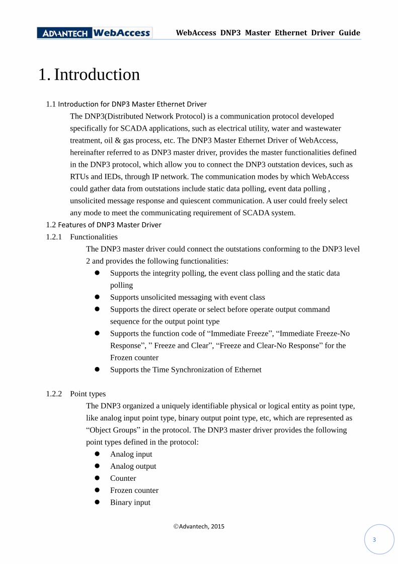
1.2.2 Point types
The DNP3 organized a uniquely identifiable physical or logical entity as point type,
like analog input point type, binary output point type, etc, which are represented as
“Object Groups” in the protocol. The DNP3 master driver provides the following
point types defined in the protocol:
Analog input
Analog output
Counter
Frozen counter
Binary input
WebAccess DNP3 Master Ethernet Driver Guide
Advantech, 2015
4
Double-bit binary input
Binary output
Control relay output block - binary output
User could map the data points of RTUs or IEDs into the TAG of WebAccess using
these point types. For detail, please refer to the “Tag Configuration”.
2. Configuration of DNP3 Master Driver
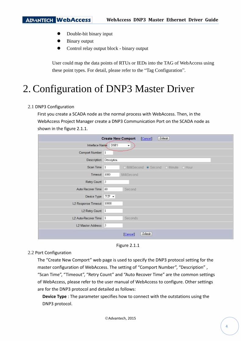
2.1 DNP3 Configuration
First you create a SCADA node as the normal process with WebAccess. Then, in the
WebAccess Project Manager create a DNP3 Communication Port on the SCADA node as
shown in the figure 2.1.1.
Figure 2.1.1
2.2 Port Configuration
The “Create New Comport” web page is used to specify the DNP3 protocol setting for the
master configuration of WebAccess. The setting of “Comport Number”, “Description” ,
“Scan Time”, “Timeout”, “Retry Count” and “Auto Recover Time” are the common settings
of WebAccess, please refer to the user manual of WebAccess to configure. Other settings
are for the DNP3 protocol and detailed as follows:
Device Type : The parameter specifies how to connect with the outstations using the
DNP3 protocol.
WebAccess DNP3 Master Ethernet Driver Guide
Advantech, 2015
5
L2 Response Timeout : The parameter specifies how long the WebAccess should wait for
the response of link layer before timing out.
L2 Retry Count : This parameter specifies how many times the WebAccess should retry
the request before the outstation is considered to be in error.
L2 Auto-Recover Time : The parameter specifies how much time the WebAccess should
wait for, then reconnect the outstation.
L2 Master Address : This parameter specifies the address of link layer of DNP3 which the
WebAccess is bound to for the Comport.
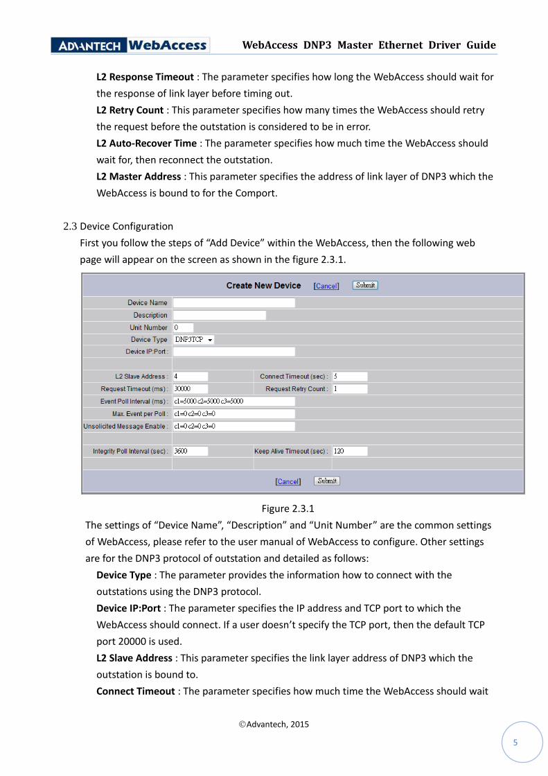
2.3 Device Configuration
First you follow the steps of “Add Device” within the WebAccess, then the following web
page will appear on the screen as shown in the figure 2.3.1.
Figure 2.3.1
The settings of “Device Name”, “Description” and “Unit Number” are the common settings
of WebAccess, please refer to the user manual of WebAccess to configure. Other settings
are for the DNP3 protocol of outstation and detailed as follows:
Device Type : The parameter provides the information how to connect with the
outstations using the DNP3 protocol.
Device IP:Port : The parameter specifies the IP address and TCP port to which the
WebAccess should connect. If a user doesn’t specify the TCP port, then the default TCP
port 20000 is used.
L2 Slave Address : This parameter specifies the link layer address of DNP3 which the
outstation is bound to.
Connect Timeout : The parameter specifies how much time the WebAccess should wait
WebAccess DNP3 Master Ethernet Driver Guide
Advantech, 2015
6
for the TCP connect request before the outstation is considered as to be in error.
Request Timeout : This parameter specifies how much time the WebAccess should wait
for the application layer request before timing out.
Request Retry Count : This parameter specifies how many times the WebAccess should
try to resent the application layer request before the request is considered as to be in
error.
Event Poll Interval : The parameter specifies how much time the WebAccess should wait
for each event class to issue the event poll request. A user could assign zero to the
interval of event class to disable the corresponding event poll request.
Max. Event per Poll : This parameter specifies the maximum number events could be
retrieved per the event poll request. A user could assign zero to this field to delimit the
count of event.
Unsolicited Message Enable : This parameter specifies whether the WebAccess should
enable the unsolicited message response for the event class.
Integrity Poll Interval : The parameter specifies how much time the WebAccess should
wait for to issue the class 0, 1, 2 and 3 request data.
Keep Alive Timeout : This parameter specifies the time elapses without any
communication from the outstation to transmit a keep-alive status request to the
outstation. A user could disable this feature by assigning zero to this field.
2.4 Tag Configuration
The DNP3 master driver uses the form “GRP.VAR.IDX /OPTIONS” as the WebAccess “Address”
that maps from the address of point type of DNP3 outstation to the TAG name of WebAccess,
where:
GRP: the object group of point type
VAR: the variation specifies the data type of object group requested
IDX: The specified identification of point type in a given group
/OPTIONS: The options give the operating request supported by a given group
The following sections detail the tag configuration of point type supported by the WebAccess.
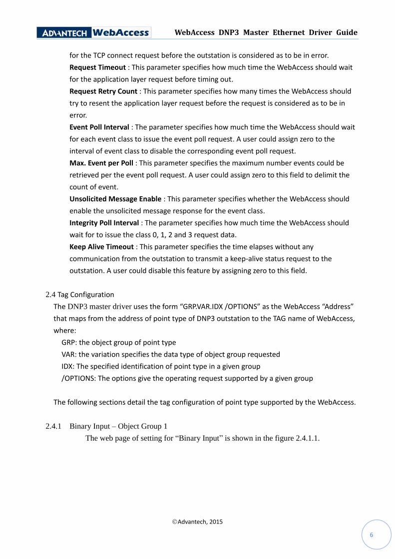
2.4.1 Binary Input – Object Group 1
The web page of setting for “Binary Input” is shown in the figure 2.4.1.1.
WebAccess DNP3 Master Ethernet Driver Guide
Advantech, 2015
7
Figure 2.4.1.1
The option “/rdm” specifies how to retrieve the data from outstation by the
WabAccess:
sp : static data polling
c0: event class 0 polling
c1: event class 1 polling
c2: event class 2 polling
c3: event class 3 polling
un: unsolicited message response
A user must specify one of modes to retrieve the data from outstation. The VAR is
recommended to 0 that means the outstation will return the data type by its default
setting.
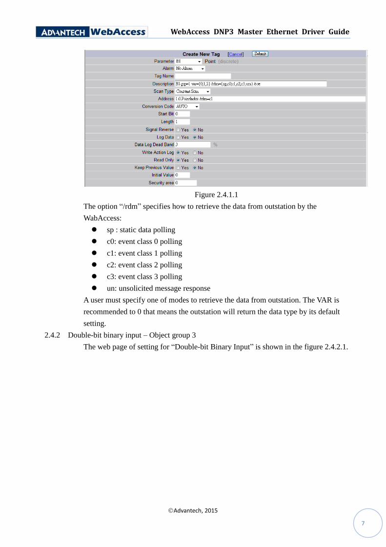
2.4.2 Double-bit binary input – Object group 3
The web page of setting for “Double-bit Binary Input” is shown in the figure 2.4.2.1.
WebAccess DNP3 Master Ethernet Driver Guide
Advantech, 2015
8
Figure 2.4.2.1
The option “/rdm” specifies how to retrieve the data from outstation by the
WabAccess:
sp : static data polling
c0: event class 0 polling
c1: event class 1 polling
c2: event class 2 polling
c3: event class 3 polling
un: unsolicited message response
A user must specify one of modes to retrieve the data from outstation. The VAR is
recommended to 0 that means the outstation will return the data type by its default
setting.
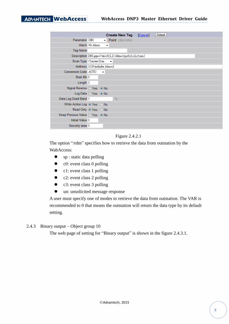
2.4.3 Binary output – Object group 10
The web page of setting for “Binary output” is shown in the figure 2.4.3.1.
WebAccess DNP3 Master Ethernet Driver Guide
Advantech, 2015
9
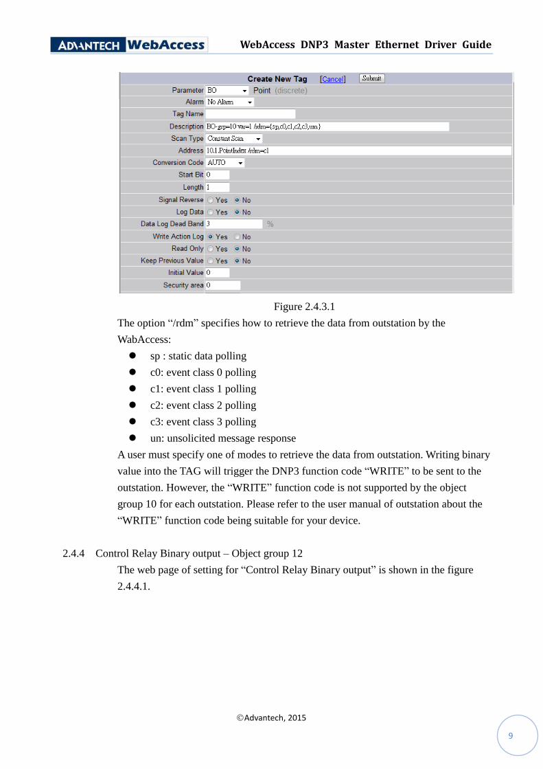
Figure 2.4.3.1
The option “/rdm” specifies how to retrieve the data from outstation by the
WabAccess:
sp : static data polling
c0: event class 0 polling
c1: event class 1 polling
c2: event class 2 polling
c3: event class 3 polling
un: unsolicited message response
A user must specify one of modes to retrieve the data from outstation. Writing binary
value into the TAG will trigger the DNP3 function code “WRITE” to be sent to the
outstation. However, the “WRITE” function code is not supported by the object
group 10 for each outstation. Please refer to the user manual of outstation about the
“WRITE” function code being suitable for your device.
2.4.4 Control Relay Binary output – Object group 12
The web page of setting for “Control Relay Binary output” is shown in the figure
2.4.4.1.
WebAccess DNP3 Master Ethernet Driver Guide
Advantech, 2015
10
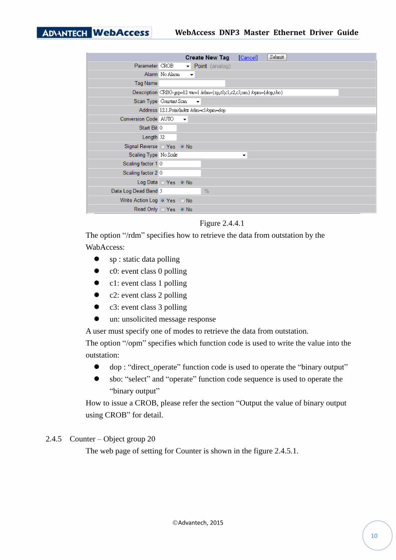
Figure 2.4.4.1
The option “/rdm” specifies how to retrieve the data from outstation by the
WabAccess:
sp : static data polling
c0: event class 0 polling
c1: event class 1 polling
c2: event class 2 polling
c3: event class 3 polling
un: unsolicited message response
A user must specify one of modes to retrieve the data from outstation.
The option “/opm” specifies which function code is used to write the value into the
outstation:
dop : “direct_operate” function code is used to operate the “binary output”
sbo: “select” and “operate” function code sequence is used to operate the
“binary output”
How to issue a CROB, please refer the section “Output the value of binary output
using CROB” for detail.
2.4.5 Counter – Object group 20
The web page of setting for Counter is shown in the figure 2.4.5.1.
WebAccess DNP3 Master Ethernet Driver Guide
Advantech, 2015
11
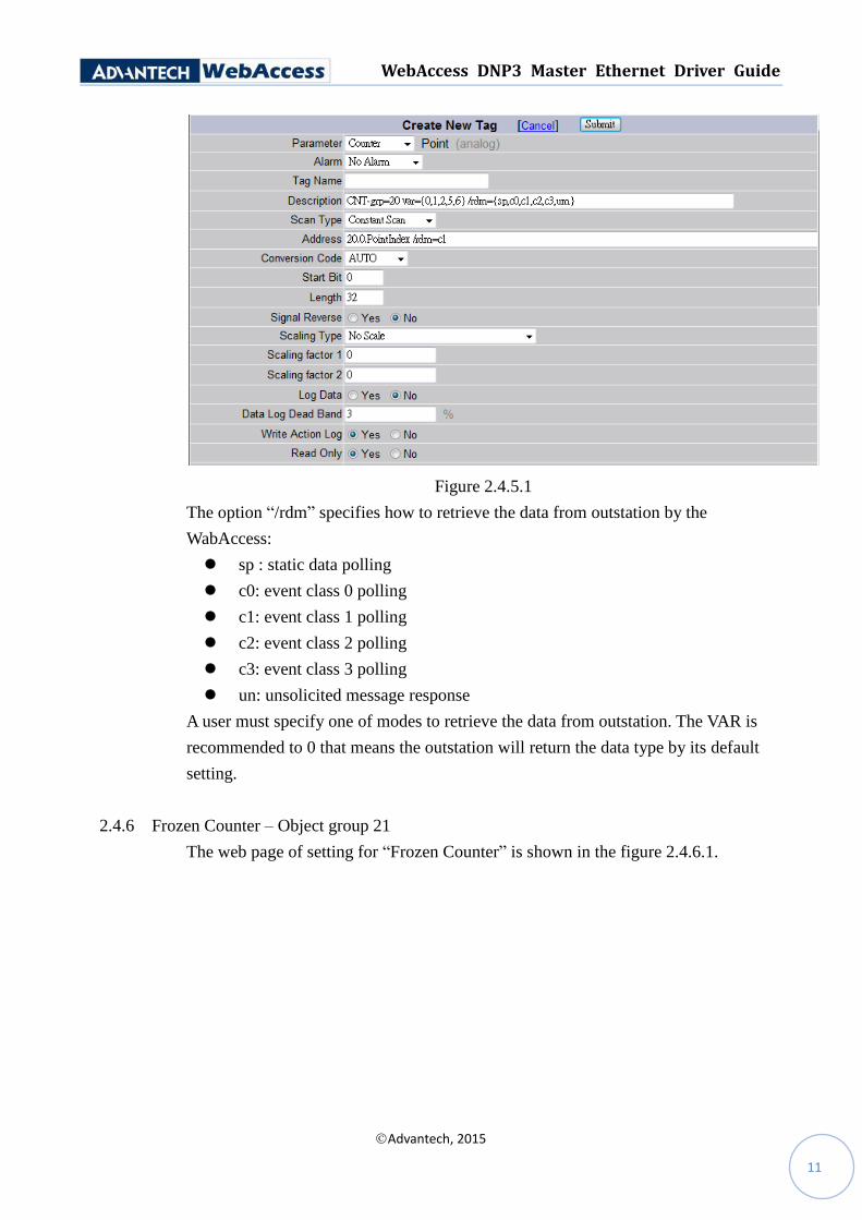
Figure 2.4.5.1
The option “/rdm” specifies how to retrieve the data from outstation by the
WabAccess:
sp : static data polling
c0: event class 0 polling
c1: event class 1 polling
c2: event class 2 polling
c3: event class 3 polling
un: unsolicited message response
A user must specify one of modes to retrieve the data from outstation. The VAR is
recommended to 0 that means the outstation will return the data type by its default
setting.
2.4.6 Frozen Counter – Object group 21
The web page of setting for “Frozen Counter” is shown in the figure 2.4.6.1.
WebAccess DNP3 Master Ethernet Driver Guide
Advantech, 2015
12
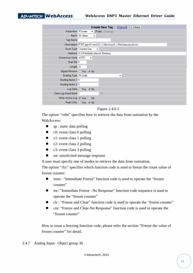
Figure 2.4.6.1
The option “/rdm” specifies how to retrieve the data from outstation by the
WabAccess:
sp : static data polling
c0: event class 0 polling
c1: event class 1 polling
c2: event class 2 polling
c3: event class 3 polling
un: unsolicited message response
A user must specify one of modes to retrieve the data from outstation.
The option “/frz” specifies which function code is used to freeze the count value of
frozen counter:
imm : “Immediate Freeze” function code is used to operate the “frozen
counter”
inr: “Immediate Freeze –No Response” function code sequence is used to
operate the “frozen counter”
clr : “Freeze and Clear” function code is used to operate the “frozen counter”
cnr: “Freeze and Clear-No Response” function code is used to operate the
“frozen counter”
How to issue a freezing function code, please refer the section “Freeze the value of
frozen counter” for detail.
2.4.7 Analog Input– Object group 30
WebAccess DNP3 Master Ethernet Driver Guide
Advantech, 2015
13
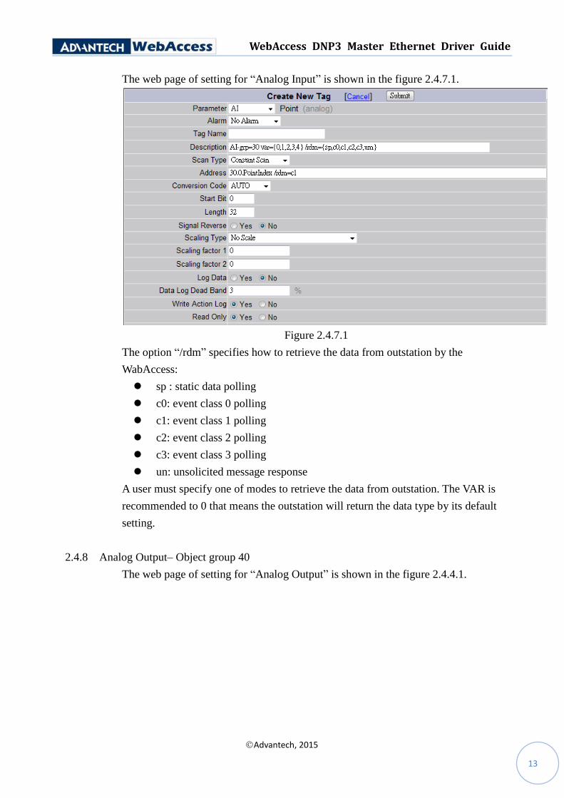
The web page of setting for “Analog Input” is shown in the figure 2.4.7.1.
Figure 2.4.7.1
The option “/rdm” specifies how to retrieve the data from outstation by the
WabAccess:
sp : static data polling
c0: event class 0 polling
c1: event class 1 polling
c2: event class 2 polling
c3: event class 3 polling
un: unsolicited message response
A user must specify one of modes to retrieve the data from outstation. The VAR is
recommended to 0 that means the outstation will return the data type by its default
setting.
2.4.8 Analog Output– Object group 40
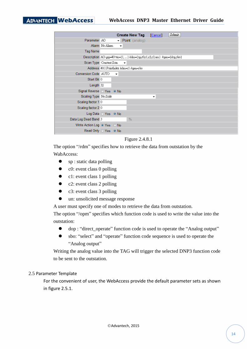
The web page of setting for “Analog Output” is shown in the figure 2.4.4.1.
WebAccess DNP3 Master Ethernet Driver Guide
Advantech, 2015
14
Figure 2.4.8.1
The option “/rdm” specifies how to retrieve the data from outstation by the
WabAccess:
sp : static data polling
c0: event class 0 polling
c1: event class 1 polling
c2: event class 2 polling
c3: event class 3 polling
un: unsolicited message response
A user must specify one of modes to retrieve the data from outstation.
The option “/opm” specifies which function code is used to write the value into the
outstation:
dop : “direct_operate” function code is used to operate the “Analog output”
sbo: “select” and “operate” function code sequence is used to operate the
“Analog output”
Writing the analog value into the TAG will trigger the selected DNP3 function code
to be sent to the outstation.
2.5 Parameter Template
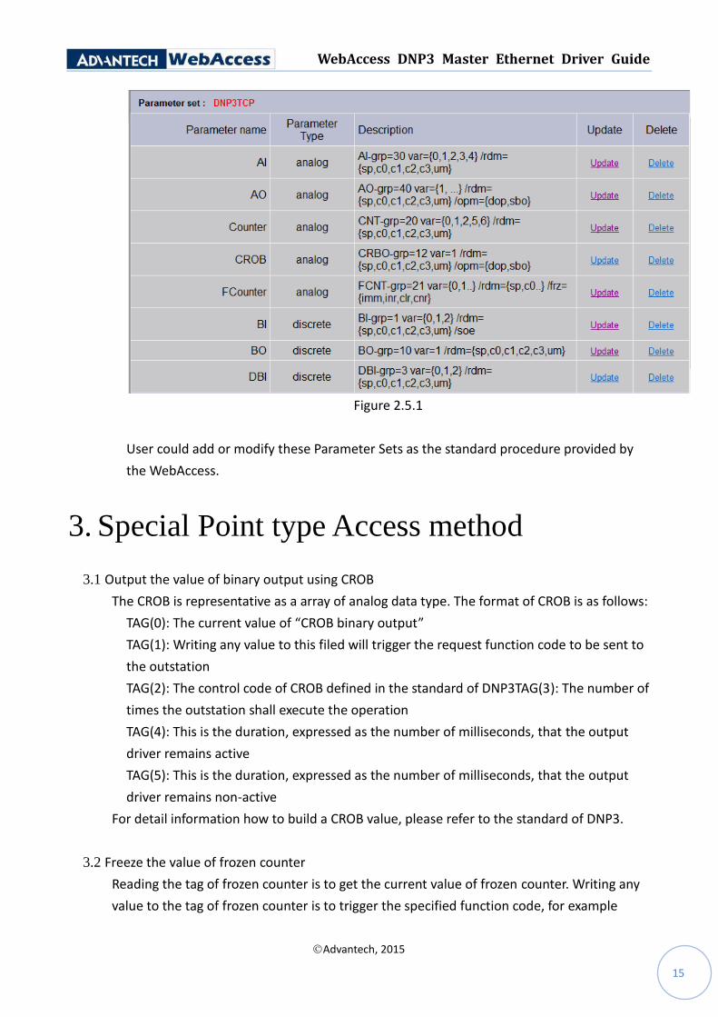
For the convenient of user, the WebAccess provide the default parameter sets as shown
in figure 2.5.1.
WebAccess DNP3 Master Ethernet Driver Guide
Advantech, 2015
15
Figure 2.5.1
User could add or modify these Parameter Sets as the standard procedure provided by
the WebAccess.
3. Special Point type Access method
3.1 Output the value of binary output using CROB
The CROB is representative as a array of analog data type. The format of CROB is as follows:
TAG(0): The current value of “CROB binary output”
TAG(1): Writing any value to this filed will trigger the request function code to be sent to
the outstation
TAG(2): The control code of CROB defined in the standard of DNP3TAG(3): The number of
times the outstation shall execute the operation
TAG(4): This is the duration, expressed as the number of milliseconds, that the output
driver remains active
TAG(5): This is the duration, expressed as the number of milliseconds, that the output
driver remains non-active
For detail information how to build a CROB value, please refer to the standard of DNP3.
3.2 Freeze the value of frozen counter
Reading the tag of frozen counter is to get the current value of frozen counter. Writing any
value to the tag of frozen counter is to trigger the specified function code, for example

WebAccess DNP3 Master Ethernet Driver Guide
Advantech, 2015
16
“Immediate Freeze”, to be sent to the outstation.
3.3 Add the SOE feature to a data point
User could add the option “/soe” to the tag address to indicate the changed value will be
logged in the SOE log file.


