148
356943.063 Configuration Program DC Power Supply System Compack and Smartpack Based Systems . User's Guide WebPower Help
| Date post: | 08-Dec-2015 |
| Category: |
Documents |
| Upload: | eric-herrera |
| View: | 79 times |
| Download: | 16 times |

356943.063
Configuration Program DC Power Supply System
Compack and Smartpack Based Systems
.
User's Guide
WebPower Help

Information in this document is subject to change without notice and does not represent a commitment on the part of Eltek Valere. No part of this document may be reproduced or transmitted in any form or by any means — electronic or mechanical, including photocopying and recording — for any purpose without the explicit written permission of Eltek Valere.
Copyright ©: Eltek Valere, 2009
356943.063 Issue 1.0c, 2009 Sep Published 2009-09-15 Mfm
NS-EN ISO 14001 Certified
Certificate No: 11276-2007-AE-NOR-NA
NS-EN ISO 9001 Certified
Certificate No:4072-2007-AQ-NOR-NA


User Guide WebPower Help Contents v
Contents
WebPower Help 1
Welcome to WebPower ............................................................................................................. 1 Getting Started ........................................................................................................................... 3
About the WebPower Firmware .................................................................................. 3 Compack Controller..................................................................................................... 4 Smartpack Controller................................................................................................... 4 Accessing the Controller and Logging In to WebPower ............................................. 5
Understanding the WebPower Interface .................................................................................... 7 WebPower Home Page ................................................................................................ 7
Using WebPower ..................................................................................................................... 11 Toolbar web pages ..................................................................................................... 11 Power Explorer Pane web pages ............................................................................... 28
Functionality Description 31
Functionality Overview ........................................................................................................... 31 Power System Functions .......................................................................................................... 31
About AC, DC Earthing Systems .............................................................................. 32 CAN bus Termination ............................................................................................... 32 Power System‘s Operation Mode .............................................................................. 33 Alarm Reset ............................................................................................................... 34 System Voltages ........................................................................................................ 34 Alarm Messages, (Log) ............................................................................................. 36 System Calibration .................................................................................................... 36
Mains Functions....................................................................................................................... 40 Mains Phase Assignment versus Rectifier ID............................................................ 40
Rectifier Functions ................................................................................................................... 40 Plug-and-Play Rectifiers ............................................................................................ 41 Resetting the Number of Rectifiers ........................................................................... 41 Rectifier Information ................................................................................................. 41 Rectifier Status - Alarm Levels ................................................................................. 43
Battery Functions ..................................................................................................................... 43 Battery Banks, Strings and Blocks ............................................................................ 43 Overview Battery Measurements .............................................................................. 45 Battery Symmetry Measurements ............................................................................. 46 Battery Symmetry Calculations ................................................................................. 49 Battery Tables ............................................................................................................ 52 Battery Tests .............................................................................................................. 54 Discontinuance Battery Test ...................................................................................... 58 Temperature Compensated Charging ........................................................................ 59 Battery Charging Current Limitation......................................................................... 61 Battery Temperature Levels ~ ―BatteryLifeTime‖ monitor ...................................... 62 LVBD - Battery Protection ........................................................................................ 63
Load Functions ........................................................................................................................ 65 LVLD ~ Non-Priority Load Disconnection ............................................................... 65 Load Current Calculation .......................................................................................... 66
Control System Functions ........................................................................................................ 66 CAN bus Addressing ................................................................................................. 66 System Inputs and Outputs - Overview ..................................................................... 69 Control Units, Controllers, CAN Nodes, etc ............................................................. 72

vi Contents User Guide WebPower Help
Networking the Controller - Access Methods ........................................................... 77 Power System Configuration & Monitoring – Methods ............................................ 86 Firmware Upgrade ..................................................................................................... 94 Alarm Monitors ....................................................................................................... 100 Alarm Output Groups .............................................................................................. 102
About Eltek Valere ................................................................................................................ 103 Compliance to International Standards .................................................................... 103 Forefront Telecom Power Products ......................................................................... 103
FAQs 105
Frequently Asked Questions, FAQs ...................................................................................... 105 Generic FAQs .......................................................................................................... 105 WebPower FAQs ..................................................................................................... 105 PowerSuite FAQs .................................................................................................... 115
Glossary of Terms 119
Index 137

User Guide WebPower Help WebPower Help 1
WebPower Help
Welcome to WebPower WebPower Online Help System, 356943.067, 1v0c, 2009-09-15
The pane on the left is a Table of Contents, a complete list of all topics. You
can click on the Index button, on the toolbar, to get a list of all topics in
alphabetical order.
You can also search for answers by using the Search button on the toolbar.
Tips for searching Help:
Limit the number of words you type in the search box
Make sure that your search terms are spelled correctly
Save useful topics by clicking on the Add to Favorites button on the
toolbar
WebPower Online Help is divided into the following sections:
―Getting Started‖ on page 3
Provides introductory information about WebPower. It also includes
explanation of important concepts, system requirements, about the
controllers, how to log in, the program‘s access levels, etc.
―Understanding the WebPower Interface‖ on page 7
Describes the location of the different elements in the WebPower user
interface, the home page window, the window panes, icons, toolbar, etc.
―Using WebPower‖ on page 11
Provides detailed information about the web-based user interface, the
configuration web pages, subpages and commands. It also explains
procedures to accomplish common system configuration tasks using
WebPower
Functionality Overview (page 31)
Offers an overview of topics with more detailed descriptions of the
functionality implemented in Eltek Valere‘s DC power systems.
FAQs (page 105)
where you can find answers to some of the most Frequently Asked
Questions about Eltek Valere‘s DC power systems.
Glossary of Terms (page 119)
Clarifies expressions, technical terms, functions, etc. used in Eltek
Valere‘s DC power systems.

WebPower
2 356943.063_mfm_2009-dd User Guide WebPower Help
Your DC Power System is a modern and cost-effective power supply system,
specifically developed by Eltek Valere for telecom and industrial applications.
The WebPower firmware provides a platform-independent graphical user
interface (GUI), employed to configure and operate Micropack, Minipack,
Flatpack2 and Powerpack DC power supply systems using a standard Web
browser.
WebPower Online Help is designed to help you get started using WebPower, the
web-based user interface (GUI). It also contains overview information and
procedural steps for performing common configuration tasks.
Internet or
LAN

WebPower
User Guide WebPower Help 356943.063_mfm_2009-dd 3
Getting Started
This section provides introductory information about the WebPower firmware. It
also includes an explanation of important concepts, system requirements, about
the controllers, how to log in, the program‘s access levels, etc.
About the WebPower Firmware
The WebPower firmware enables you to configure the DC power system, and
represents a graphical interface between you and the system.
WebPower also provides you with a graphical interface for local or remote
monitoring and control of the DC power system.
Globally available remote access provides many advantages to the system‘s
operation group. The WebPower graphical user interface (GUI) is an
environment familiar to Internet users.
The WebPower firmware‘s main features are:
Platform independence The monitoring computer can be a Windows, Macintosh, UNIX or
Linux based computer, or any modern operating system and hardware
platform that support a standard Web browser capable of running
JavaScript.
Requires no software installation All data is exchanged using standard HTTP Internet protocol.
Field upgrades of the WebPower firmware
Possible over the network connection. No special hardware is required.
A simple Windows software tool is provided (requires no installation)
for remote firmware upgrading of one or all controllers.
Multiple concurrent browser connections
This feature may be utilized for cooperative troubleshooting efforts,
training purposes, or other collaborative, multi-user sessions.
Access security
Three group access levels are provided, to restrict unauthorized
attempts to alter system settings.
Protection of the WebPower operating firmware The operating firmware is executed from RAM, so there is no file
system to corrupt or damage. This RAM area is not accessible
externally, providing excellent security against malicious attacks. In the
event of corrupted RAM, rebooting the controller literally loads a fresh
copy of the operating code.
Ethernet Local Area Network (LAN)
Compack controller
Server
WebPower Configuration via web browser
(Example of Compack controller access via LAN)

WebPower
4 356943.063_mfm_2009-dd User Guide WebPower Help
Embedded SNMP Agent Provides standard SNMP traps upon occurrences of alarm conditions,
and allows GET and SET operations in order to retrieve data and
perform remote operations on the power plant. The appropriate MIB
files are provided with the WebPower firmware.
Compack Controller
The Compack controller is a DIN rail mounted monitoring and
control unit used in the Micropack DC power systems. The
controller is also used in larger Eltek Valere‘s Compack-based
power systems.
It monitors and controls the whole system, and implements several
network protocols for local and remote system configuration via Web browser
and existing network management system (NMS).
Using the UDP tunneling protocol, the powerful PowerSuite application may
also be used for system configuration from a local or remote Internet connected
personal computer.
You can easily connect the Compack controller to an Ethernet networked
computer, plugging a standard Ethernet cable to the RJ-45 socket on top of the
controller and to any available Ethernet socket on the network.
The Compack controller‘s I/O cables are connected to pluggable terminal blocks
located on the controller‘s top. These connections are used for monitoring and
controlling the status of external equipment, using configurable inputs and
voltage-free alarm relays contacts.
The Compack controller has the following LED indications:
Alarm (red) indicates an alarm situation (major alarm)
Warning (yellow) indicates an abnormal situation (minor alarm)
―Power‖ (green) indicates that the power supply is ON or OFF
Read more about the controller, networking and monitoring methods in the
Control System Functions (page 66) topic, in the Functionality Description
section.
Smartpack Controller
The Smartpack controller is a monitoring and control unit
used as the vital nerve center of the DC power plant. You
operate the system directly from the elegant front panel,
using three front keys and the LCD-display; they represent
the main interface between you and the system.
You can also operate the system remotely via modem, Ethernet and the Web.
The module then utilizes the USB or RS232 ports to interface with NMS or Web
adapters.
The Smartpack controller‘s standard front panel consists of a three-button
keypad, a graphic display, an USB port and 3 LED lamps.
The Smartpack controller has the following LED indications:
Alarm (red) indicates an alarm situation (major alarm)
Warning (yellow) indicates an abnormal situation (minor alarm)
―Power‖ (green) indicates that the power supply is ON or OFF
You can operate the DC power system from the Smartpack controller, by means
of display menus and sub-menus.

WebPower
User Guide WebPower Help 356943.063_mfm_2009-dd 5
For more advanced operation, you can use the WebPower GUI from a computer,
or install and run the PowerSuite application.
Read more about the controller, networking and monitoring methods in the
Control System Functions (page 66) topic, in the Functionality Description
section.
Accessing the Controller and Logging In to WebPower
Access Methods
You can access the controller‘s web-based configuration pages with a computer,
either remotely via a LAN network or locally via a stand-alone computer.
Find detailed information on the required steps to access the controller on the
Networking the Controller – Access Methods (page 77) topic, in the
Functionality Description section.
Log In to WebPower
When you first access the controller‘s web-based GUI from your computer‘s
Internet browser, you have to log in using one of the following three factory set,
default accounts:
Login
Account
User
Name
Password Access
Level
Note
1 admin admin Factory (or ADMIN) Administration access rights
2 control control Service (or CONTROL) Service access rights
3 status status User (or STATUS) Read only access rights
4 -- -- Factory or Service or User User defined
-- -- -- Factory or Service or User User defined
10 -- -- Factory or Service or User User defined
(Case sensitive passwords)
For security reasons, it is advisable to log in with the ―admin‖ account (case
sensitive) and change the default passwords with the passwords of your choice.
Find detailed information on how to log in to WebPower and change the default
passwords in topic How to Change WebPower‘s Default Log in Passwords (page
106) in the FAQs section.
If required, you can create up to 10 different User Login Accounts – with
different user names and passwords – but each account can only be granted to
one of the three described access levels.
Access Levels
WebPower web-based GUI protects system parameters and other configured
values with three different access levels. These correspond to the access levels
used by the controller. The three levels are:
User Access Level (or STATUS)
is the default level. You can read all parameters and values in the
configuration web pages (Read Access), but changing them is not

WebPower
6 356943.063_mfm_2009-dd User Guide WebPower Help
allowed.
Default, factory set user name and password: <status>
Service Access Level (or CONTROL)
By logging in to this level you can change most of the system
parameters and values available in the configuration web pages (Write
Access).
Default, factory set user name and password: <control>
Factory Access Level (or ADMIN)
As the name indicates, only system responsible personnel will have
access to change certain critical values.
Default, factory set user name and password: <admin>
You can find the Access Level assigned to the User Login Account you used to
log in, by looking at the Power Summary pane (top right). Refer also to the topic
―WebPower Home Page‖ on page 7.

WebPower
User Guide WebPower Help 356943.063_mfm_2009-dd 7
Understanding the WebPower Interface
This section describes the location of the different elements in the WebPower
user interface, the home page window, the window panes, icons, toolbar, etc.
WebPower Home Page
When you open WebPower in the web browser, the home page window appears.
This window is your web-based configuration interface. It contains the
commands and tools you need to configure the power supply system.
The Power Explorer pane (1) displays a hierarchical tree structure of
configuration web pages (7) and subpages (8) that you can click to open in the
Working Area (2) or in a new window.
Clicking on the buttons in the WebPower toolbar (4) will open configuration web
pages in new windows.
Note that the web browser must have the Pop-ups function enabled, as the
configuration web pages employ Java script navigation. Read topic How to
Enable Pop-ups in the browser -- Internet Explorer (page 105) in the FAQs
section.
The web-based interface‘s components and main areas are:
1 2
4 3
5 6
7
8

WebPower
8 356943.063_mfm_2009-dd User Guide WebPower Help
Power Explorer pane (1)
The Power Explorer pane (1) displays a hierarchical tree structure (Windows
Explorer style) with coloured icons and expandable branches. The tree represents
the main components in the power supply system.
The coloured icons represent the ―health‖ of the groups and the units:
-- Green: No alarm
-- Yellow: Minor alarm
-- Red: Major Alarm
-- Gray: unconnected or malfunctioning unit
To expand and collapse the branches of web pages (7) and sub-pages (8), you
can click on the ―+‖ and ―-― symbols on the icons‘ left side (9). Thus the
branches will be displayed or hidden.
The Working Area (2)
The working area (2) displays the configuration web pages and subpages that
you select when you click on the icons on the Power Explore pane (1).
Some configuration web pages and subpages may have links, as the Load Bank
subpage (10) for example. Clicking on these links will open a new subpage in a
new window (11).
7
8
8 7
9

WebPower
User Guide WebPower Help 356943.063_mfm_2009-dd 9
Power Summary (3) pane
The Power Summary pane (3) -- located under the WebPower toolbar (4) --
shows an overview of the power system‘s most important parameters, displayed
in a summary table.
It also displays the WebPower Access Level (15) assigned to the User Login
Account you used to log in, and the power System Status (14), whether it is in
normal or critical condition, as well as its operating mode and system time.
Read also the Power System‘s Operation Mode (page 33) topic in the
Functionality Description section.
The ―LoadCurrent‖ alarm monitor (12) does not really measure the
load current. It raises alarms based on the calculation of the load current
(the difference between the rectifier current ―RectifierCurrent‖ and the
battery current ―BatteryCurrent‖). Read also the Load Current
Calculation (page 66) topic in the Functionality Description section.
In addition to the Power Summary pane, this alarm monitor is also
displayed in ―Load web page‖ on page 29.
The ―BatteryCurrent‖ and the ―BatteryTemp‖ alarm monitors (13)
do not really measure these values either.
The ―BatteryCurrent‖ alarm monitor generates alarms based on the
addition of the current measurements performed by the individual
battery current alarm monitors;
4 3
12 13 14 15
16
1
2
11
10

WebPower
10 356943.063_mfm_2009-dd User Guide WebPower Help
see the Currents tab in topic ―Battery Bank nn subpage‖ on page 29.
The ―BatteryTemp‖ alarm monitor generates alarms based on the
highest temperature measurement performed by the individual battery
temperature alarm monitors;
see the Temperatures tab in topic ―Battery Bank nn subpage‖ on page
29.
In addition to the Power Summary pane, these alarm monitor are also
displayed in the ―Battery web page‖ on page 29.
The ―RectifierCurrent‖ alarm monitor (16) does not really measure
the rectifier current. It raises alarms based on the addition of all the
rectifier currents.
In addition to the Power Summary pane, this alarm monitor is also
displayed in ―Rectifiers web page‖ on page 29
Toolbar - WebPower (4)
The WebPower toolbar (4) displays buttons for commonly used commands.
Clicking on the buttons will open configuration web pages in new windows.
For more information, read ―Toolbar web pages‖ on page 11.
Toolbar - Internet Browser (5)
The browser‘s toolbar shows the menu bar and toolbar in the standard web
browser that you use to open the WebPower configuration pages.
Web Address Line - WebPower (6)
It shows the web address of the power system‘s configuration web pages, as
usual in standard web browsers.

WebPower
User Guide WebPower Help 356943.063_mfm_2009-dd 11
Using WebPower This section provides detailed information about the web-based user interface,
the configuration web pages, subpages and commands. It also explains
procedures to accomplish common system configuration tasks using WebPower.
WebPower has 2 main functional areas, where you open configuration web pages
and subpages to interact and configure the DC power supply system.
o Toolbar
o Power Explorer pane
Toolbar web pages
This topic describes the configuration web pages accessible from the WebPower
toolbar. Refer to the ―Toolbar - WebPower (4)‖ link on the topic ―WebPower
Home Page‖ on page 7.
System Voltage Levels web page
This configuration web page is displayed by clicking on the ―System Voltage
Levels‖ button on the WebPower toolbar; refer to the ―Toolbar - WebPower (4)‖
link on the topic ―WebPower Home Page‖ on page 7.
o If required, edit the voltage parameters by
clicking on the text fields and typing other values
o Click on the Save button, to save the changes
o WARNING: To register and edit the data you must log in using an account with Access Level Factory (Admin) or Service (Control).
This configuration web page presents you with a summary of the most important
voltage parameters in the power system, allowing you to edit the values.
System Voltage Levels

WebPower
12 356943.063_mfm_2009-dd User Guide WebPower Help
Reference Voltage: read more in the Battery pages, in the ―Configuration subpage (battery)‖ on
page 29
Boost Voltage: read more in the Battery pages, in the ―Battery Boost subpage‖ on page 29
Battery Test End Voltage: This parameter is not editable. It is calculated from the end-voltage per cell that
you may enter in the Battery pages, in the ―Battery Test subpage‖ on page 29
Rectifier Standby Voltage:
which indicates the rectifiers‘ output voltage during battery testing. This
voltage must be lower than the battery‘s End-of-Discharge Voltage. For more
information about battery testing, see topic Battery Tests (page 31), in the
Functionality Description section.
Rectifier OVS Voltage: read more about the Rectifier Over-Voltage-Shutdown (OVS) voltage limit in
the Rectifier pages, in the ―Configuration subpage (rectifiers)‖ on page 29
Battery Disconnect and Reconnect Voltages:
read more in the Battery pages, in the ―LVBD subpage‖ on page 29
System Configuration web page
This configuration web page is displayed by clicking on the ―System
Configuration‖ button (1) on the WebPower toolbar; refer to the ―Toolbar -
WebPower (4)‖ link on the topic ―WebPower Home Page‖ on page 7.
System Configuration web page enables you -- in the Map Coordinates tab --
to register the exact global position where the DC power system is installed. It
also enables you -- in the Password tab -- to change the access level, the user
name and password of up to 10 logging accounts.
Click on the actual tab (2) to display its data.
Map Coordinates tab
The Map Coordinates tab -- in the System Configuration web page -- enables
you to register the exact global position where the DC power system is installed.
System Configuration
2
1

WebPower
User Guide WebPower Help 356943.063_mfm_2009-dd 13
The global position is specified using a geographic coordinate system with 3
coordinates: latitude, longitude and elevation.
WARNING: To register and edit the data you must log in using an account with Access Level Factory (Admin).
The global position data is stored in the controller, and used by the MultiSite
Monitoring PC Application software to dynamically display the position of
power system installations in maps.
o If required, select the desired data format and register the parameters
by clicking on the text fields and typing appropriate values
o Click on the Save button, to save the changes
The exact global position is determined by entering the Map Coordinates:
Latitude, Longitude and Elevation.
Data Format: click on the radio button for the data format you want to register with:
-- Sexagesimal Notation: DDº MM’ SS.ss’’ N or S
Degrees (º), minutes (’) and seconds (’’). For greater precision, use the
decimal fraction of seconds: SS.ss.
North (N) or South (S) of the equator.
E.g.: 66º 33‘ 38.95‘‘ N
OR
-- Decimal Notation: [DDD.dddddd] Degrees, with the minutes and seconds expressed as a decimal fraction
of degrees.
Positive degrees (e.g. 66.456) indicate positions north for equator.
Negative degrees (e.g. -66.456) indicate positions south for equator.
Latitude: (<DD>º<MM>’ <SS.ss>’’ N/S) Latitude is the angular distance, measured north or south from the
equator, of a place on the Earth's surface, usually expressed in degrees.
Parallels are imaginary lines along all the places on the Earth with the
System Configuration

WebPower
14 356943.063_mfm_2009-dd User Guide WebPower Help
same latitude.
Latitude ranges from 0º at the equator to 90ºN (or +90º) at the North
Pole; and to 90ºS (or -90º) at the South Pole.
Enter the power system‘s latitude in the selected Data Format.
Longitude: Longitude is used to denote the location of a place on the Earth's
surface east or west of the prime meridian.
A meridian is an imaginary line from the North Pole to the South Pole
that connects all locations with the same longitude. The position of a
point on the meridian is given by the latitude.
The Prime Meridian is, by international convention, one passing
through the Royal Observatory, Greenwich, in east London, United
Kingdom, known as the International Meridian or Greenwich Meridian.
Longitude is given as an angular measurement ranging from 0° at the
Prime Meridian to +180° eastward (or 180°E) and −180° westward (or
180°W).
Enter the power system‘s longitude in the selected Data Format.
Elevation: Elevation, or altitude, is used to indicate how high a place on the Earth's
surface is from sea level (above mean sea level, AMSL).
Enter the power system‘s elevation in meters above sea level (AMSL).
Password tab
The Password tab (2) -- in the System Configuration web page -- enables you to
change the access level, the user name and password of up to 10 logging
accounts.
NOTICE: To register and edit the data you must log in using an account with Factory (or Admin) Access Level. Otherwise, you are only able to change your account’s password (requires also the administrator’s password).
You can find the Access Level assigned to the User Login Account you used to
log in, by looking at the Power Summary pane (top right). Refer also to the topic
―WebPower Home Page‖ on page 7.

WebPower
User Guide WebPower Help 356943.063_mfm_2009-dd 15
o If required, select the desired user name, access level and password (3,
4 and 5) for the displayed account number, by clicking on the text
fields, radio buttons and typing appropriate values.
o Click on the Save button (6), to save the changes
The configuration web page displays the User Login Account you used to log in;
e.g. ―...account #1‖. If this account‘s access level is ―administrator / factory‖,
then you can edit the following:
Current User Name (3): click on the text field and type a new user name for this account
Access Level (4): click on the radio button for the Access Level you want to assign to this
account, e.g. the radio button for ―administrator / factory‖.
Read more about available access levels and default accounts in topic
―Accessing the Controller and Logging In to WebPower‖ on page 5
Password (5) fields: click on the text fields and type the login account‘s current password
(case sensitive) and twice the password you want to change to
If you are logged in using an account with Factory (or Admin) Access Level,
you will also see the ―Account Overview‖ button (7). Click on this button will
enable you to edit existing logging accounts and create new ones.
For information about how to create new User Login Accounts and how to edit
existing User Login Accounts, read topic ―How to Create New User Login
Accounts in WebPower‖ (page 109)
System Configuration
1
2
Current Access Level: “admin”
3
4
5
6 7

WebPower
16 356943.063_mfm_2009-dd User Guide WebPower Help
Battery Test Results web page
This configuration web page is displayed by clicking on the ―Battery Test
Results‖ button (1) on the WebPower toolbar; refer to the ―Toolbar - WebPower
(4)‖ link on the topic ―WebPower Home Page‖ on page 7.
The configuration web page displays a result table, where each row (2) of data
represents a battery test. The battery quality, calculated by completed battery
tests, is also displayed in one of the columns.
If required, you can
-- Sort the table, by clicking on one of the column‘s heading (3) that
you want to sort after; e.g. the ―Start Time‖ heading. An arrow head
indicates the actual sorted column
-- View more details of each battery test and export the test data to a
file in your hard disc, by clicking on the ―View‖ links (4). Refer to topic
―Battery Test Log subpage‖ on page 16
Click on the Close button (5), to close the window
For more information about how to carry out battery tests, read topic ―Battery
Test subpage‖ on page 29. If required, read also about types of battery tests in
topic Battery Tests (page 31) .
Battery Test Log subpage
The Battery Test Log subpage -- displayed by clicking on the ―View‖ links (1)
in the ―Battery Test Results web page‖ on page 16 -- enables you to view more
details of a specific battery test and export the test data to a file in your hard disc.
Battery Test Results
1
2
3 4
5
A row per Battery Test
Sorted column
View links

WebPower
User Guide WebPower Help 356943.063_mfm_2009-dd 17
The configuration web page displays the detailed test results (2), (3) for a
specific battery test, e.g. ―...Data for test id: 07‖.
You can do the following with the battery test results:
o Click on the ―Select Unit‖ drop-down arrow (4) and select the battery
bank that you want to see test results for.
o Click on the data check boxes (checked) to enable the battery test data
types to display in the table.
Click again to (unchecked) to disable the data types you do not want to
display.
o Click on the ―Get the Data‖ button (4), to display the selected types of
data in the table
AND
o Click on the ―Extract csv data to new window‖ (5), to display the
battery test results in a new browser window, where you then can save
the data as a simple file, CVS- structured (Comma Separated Values),
easy to be imported to other computer applications
For more information about how to carry out battery tests, read topic ―Battery
Test subpage‖ on page 29. If required, read also about types of battery tests in
topic Battery Tests (page 31) .
Battery Test Results
1
2 3
4
5

WebPower
18 356943.063_mfm_2009-dd User Guide WebPower Help
Event Log web page
This configuration web page is displayed by clicking on the ―Event Log‖ button
(1) on the WebPower toolbar; refer to the ―Toolbar - WebPower (4)‖ link on the
topic ―WebPower Home Page‖ on page 7.
The configuration web page displays the Event Log, which is a log of power
system events automatically registered by the system controller. The log is stored
in the system‘s control unit(s).
Read more about ―events‖ in the topic Alarm Monitors (page 31), in the
Functionality Description section.
The configuration web page enables you to do the following:
o Click on the Next Page and First Page buttons (2) to display the next
page of system events, and return to the first page respectively
o If required, click on the ―Click here‖ link (3) to display a dialog box,
where you can click in the Open or Save buttons (4) to open or save an
XLM file containing the complete log of system events (5)
Event Log
1
2
3
4
5

WebPower
User Guide WebPower Help 356943.063_mfm_2009-dd 19
o Click on the Close link, to close the Event Log window
Network Config web page
This configuration web page is displayed by clicking on the ―Network Config‖
button (1) on the WebPower toolbar; refer to the ―Toolbar - WebPower (4)‖ link
on the topic ―WebPower Home Page‖ on page 7.
The tabs for the Network Config web pages enable you to configure the
controller‘s LAN network related parameters, such as the SMTP E-mail server,
the TCP/IP related parameters, the SNMP agent and the URL of the WebPower
Online Help.
Click on the actual tab (2) to display its data.
eMail tab
The eMail tab (2) -- in the Network Config web page -- enables you to
configure the parameters for an external SMTP E-mail server that the controller
may use to send warning and alarm e-mails to specified e-mail addresses.
WARNING: To register and edit the data you must log in using an account with Access Level Factory (Admin).
Network Config
1
2

WebPower
20 356943.063_mfm_2009-dd User Guide WebPower Help
o If required, register the parameters by clicking on the text fields (3, 4,
5 & 6) and typing appropriate values
o Click on the Save button, (7) to save the changes
The parameters for an external SMTP E-mail server are determined by entering
the server IP address, a sender e-mail address and one or two receiver e-mail
addresses.
User Name: (3) click on the text field and type e-mail account‘s user name. Entering the
user name is optional.
SMTP Server IP Address: (4) click on the text field and type the IP address for the external SMTP E-
mail server, that the controller will use to send warning e-mails from.
TIP:
-- Open the ―Account Settings‖ dialog box in an e-mail program that
uses the actual E-mail server, find and jot down the server name
-- ―Ping‖ the e-mail server name in a ―Command Prompt‖ window
(DOS), to display the server‘s IP address.
e.g. ―Ping <server name>‖
The response might be: ―172.16.23.53‖
Sender Mail Address: (5) click on the text field and type a fictive e-mail address of your choice,
preferably one that describes the power system, as the server will use
this address as the sender address in the e-mails.
e.g. [email protected]
Receiver Mail Addresses: (6) click on the text fields and type one or two existing e-mail addresses,
where you want to receive the warning and alarm e-mails from the
power system
Network Config
1
3 4
5 6
7
2

WebPower
User Guide WebPower Help 356943.063_mfm_2009-dd 21
TCP/IP tab
The TCP/IP tab (2) -- in the Network Config web page -- enables you to see and
configure the controller‘s TCP/IP parameters, which allows the controller to
communicate with a standard computer, which is either connected to an existing
LAN or directly connected to the controller.
WARNING: To register and edit the data you must log in using an account with Access Level Factory (Admin).
o If required, register the parameters by clicking on the text fields (3, 4,
5 & 6) and typing appropriate values
o Click on the Save button, (8) to save the changes
WARNING: The system controller may restart, when any of the TCP/IP parameters are changed.
The TCP/IP parameters are determined by entering or changing the controller‘s
IP address and Subnet Mask. The Default Gateway and DNS Server addresses
are usually ―0.0.0.0‖.
DHCP enable: (7) click on the check box to enable (checked) or disable (unchecked) the
controller‘s Dynamic Host Configuration Protocol (DHCP).
When enabled, the controller can automatically obtain necessary access
data to operate in an existing Local Area Network (LAN), and you can
only enter data in the Device Name field.
By default, the controllers have DHCP enabled.
Read more in topic Controller‘s Default IP Address (page 78), in the
Functionality Description section.
Agent IP Address: (3)
click on the text field and type or edit the IP address the controller uses
to communicate (DHCP must be disabled).
Network Config
1
3 4
5 6
7 2
8

WebPower
22 356943.063_mfm_2009-dd User Guide WebPower Help
Read more in topic Networking the Controller - Access Methods (page
31), in the Functionality Description section.
Network Subnet Mask: (4) click on the text field and type or edit the Network Subnet Mask the
controller uses to communicate (DHCP must be disabled).
WARNING!
Never enter Network Mask (Subnet masks) <0.0.0.0> or
<255.255.255.255> as they are not valid masks, and in the worst case
may render the controller or LAN device inaccessible.
Read more in topic Controller Access -- Via Stand-alone PC (page 31),
in the Functionality Description section.
Default Gateway & DNS Server: (5) The Default Gateway and DNS Server addresses are usually ―0.0.0.0‖,
and do not need to be changed.
But if required, click on the text field and type or edit the Default
Gateway and DNS Server addresses that the controller uses to
communicate (DHCP must be disabled).
Device Name: (6)
click on the text field and type a name for the controller or LAN device.
Entering a Device Name is optional.
SNMP tab
The SNMP tab (2) -- in the Network Config web page -- enables you to see and
configure the controller‘s SNMP agent.
WARNING: To register and edit the data you must log in using an account with Access Level Factory (Admin).

WebPower
User Guide WebPower Help 356943.063_mfm_2009-dd 23
o If required, register the parameters by clicking on the text fields (3, 4,
5, 7, 8, 9 & 10) and typing appropriate values, and clicking to check or
uncheck the check box (6)
o Click on the Save button, (11) to save the changes
The controllers implement an SNMP agent which interfaces with the Network
Management System (NMS), enabling remote monitoring via the standard
SNMP messaging commands SET, GET and TRAP.
The SNMP agent responds to SNMP‘s GET and SET commands, and forwards
TRAPs to designated recipients when critical conditions occur to the DC power
system, as configured in the controller.
The GET commands provide the NMS with remote monitoring status — e.g.
Battery status, etc. — of the power system.
The SET commands enable the NMS to remote control the power system, e.g.
changing the output voltage.
The TRAP commands are unsolicited alarm messages that the power system
sends to the NMS, when critical situations occur.
Read more in topic Monitoring -- via Network Management System (page 31),
in the Functionality Description section.
TRAP Receiver Address XX: (3)
click on the text fields and type the NMS IP addresses of up to 10
TRAP hosts that will receive the alarm messages
WARNING!
Address ―255.255.255.255‖ is not allowed on the traps‘ address fields.
Community String XX: (4)
click on the text fields and type a password (TRAP Community String)
for as many NMS IP addresses as you entered in the TRAP Receiver
Address fields (3).
Network Config
1
2 3 4
6 5
7
8
9 10
11

WebPower
24 356943.063_mfm_2009-dd User Guide WebPower Help
Default password is ―public‖ (case sensitive).
NOTICE:
Community Strings or passwords can be max 19 characters long. Valid
characters are A-Z, a-z, 0-9 and special characters ~@#%^&_-+=:,. Do
not use any other characters
TRAP Repeat Rate: (5) click on the text field and type how often (from 0-10 minutes) a TRAP
message is resent to the receiver, while the alarm remains active.
Entering ―0‖ the agent will not resend the TRAP messages.
Send Off Traps: (6) click on the check box to enable (checked) or disable (unchecked) that
the controller will send a TRAP message when an alarm or event is
reset to its normal condition
Authentication & Warmstart TRAP Receiver IP: (7) click on the text field and type NMS IP address that will receive start-
up TRAP messages.
Entering ―0.0.0.0‖ the agent will not send the start-up TRAP message
Heartbeat TRAP Repeat Rate: (8)
click on the text field and type how often (from 0-10 minutes) a
―heartbeat‖ (a control TRAP message) is resent to the receiver.
Entering ―0‖ the agent will not send the control TRAP message
Read & Write Community Strings: (9) (10)
click on the text fields and type a password (TRAP Community String)
for
-- the SNMP agent‘s Read access level (9)
(Network devices issuing the SNMP GET command must be
configured with this password)
-- the SNMP agent‘s Write access level (10)
(Network devices issuing the SNMP SET command must be configured
with this password)
Default password is ―public‖ (case sensitive).
NOTICE: Community Strings or passwords can be max 19 characters long. Valid
characters are A-Z, a-z, 0-9 and special characters ~@#%^&_-+=:,. Do
not use any other characters
Online Help Files tab
The Online Help Files tab (2) -- in the Network Config web page – enables you
to change the default Web address where the controller looks for the ―WebPower
Online Help” system.
WARNING: To register and edit the data you must log in using an account with Access Level Factory (Admin).

WebPower
User Guide WebPower Help 356943.063_mfm_2009-dd 25
o If required, click on the text field (3) and type a new web address
o Click on the Save button, (4) to save the changes
The WebPower Online Help is a frequently updated Help system published on
the Internet, and accessible via a standard web browser, where you log in with a
user name and password.
You can access the WebPower Online Help by either:
1. Clicking on the ―Help‖ button (5) on the WebPower toolbar
2. Opening your standard web browser
and visiting the actual default web address, e.g.:
http://onlinedocs.eltekvalere.com/wip4/mywip/webpower
To change the WebPower Online Help default web address:
Click on the Online Help IP Address/URL text field (3)
and type the new Web address where the controller looks for the
―WebPower Online Help” system.
NOTICE!
Contact your closest Eltek Valere representative to get the active log in
details (user name and password).
Active Alarm Groups web page
This configuration web page is displayed by clicking on the ―Active Alarm
Groups‖ button (1) on the WebPower toolbar; refer to the ―Toolbar - WebPower
(4)‖ link on the topic ―WebPower Home Page‖ on page 7.
Network Config
1
2
5
3
4

WebPower
26 356943.063_mfm_2009-dd User Guide WebPower Help
The same overview of active alarms is displayed by clicking on the Outputs link
in the Power Explorer pane. Read topic ―Outputs web page‖ on page 30.
The configuration web page displays an overview of the status of all alarms
(Alarm Output Groups, AOG) in the power system.
The overview lists two sections of AOGs: one used to group alarm relay outputs
(2) and another used to group LVD latching contactors (3).
System events trigger alarm conditions in the corresponding Alarm Monitors,
which then activate the assigned Alarm Output Groups.
Read more about ―events‖ and how alarms are generated, in the topics Alarm
Monitors (page 31) and Alarm Output Groups (page 31), in the Functionality
Description section.
The configuration web page enables you to do the following:
o Click on the Reset Active Alarms button (4) to reset the system‘s
alarm monitors, and refresh the overview of Active Alarm Output
Groups.
If the events that caused the alarms are still present, the corresponding
AO Groups will again be in alarm condition
Help web page
You can read and search for information in the WebPower Online Help system,
by clicking on the ―Help‖ button on the WebPower toolbar; refer to the ―Toolbar
- WebPower (4)‖ link on the topic ―WebPower Home Page‖ on page 7.
The WebPower Online Help is a frequently updated Help system published on
the Internet, and accessible via a standard web browser, where you log in with a
user name and password.
You can access the WebPower Online Help by either:
1. Clicking on the ―Help‖ button on the WebPower toolbar
Active Alarm Groups
1 2
AO Group number
3
4
AO Group name
AO Group status

WebPower
User Guide WebPower Help 356943.063_mfm_2009-dd 27
2. Opening your standard web browser
and visiting the actual default web address, e.g.:
http://onlinedocs.eltekvalere.com/wip4/mywip/webpower
To change the WebPower Online Help default web address, if required, read
topic ―Online Help Files tab‖ on page 24.

WebPower
28 356943.063_mfm_2009-dd User Guide WebPower Help
Power Explorer Pane web pages
This topic describes the WebPower configuration web pages and subpages
accessible from the Power Explorer pane. Refer to the ―Power Explorer pane
(1)‖ on page 8.
The Power Explorer pane presents a hierarchical tree structure of the main
components in the power supply system (Windows Explorer style).
The Power System top-level group consists of several main groups (known as
‘branches‘ or ‘nodes‘ or ‗configuration web pages‘).
-- Power System (top level)
-- Mains
-- Rectifiers
-- Load
-- Battery
-- Inputs
-- Outputs
-- Control System
For information about the pane‘s colour codes and how expand or collapse the
tree, the ―Power Explorer pane (1)‖ on page 8.
Power System
Following configuration web pages are used to interact with DC power supply
system, and configure it with parameters that apply to the system in general.
Power System web page
This configuration web page is displayed by clicking on the Power System link
in the Power Explorer pane.
For information about the pane‘s colour codes and how expand or collapse the
tree, read ―Power Explorer pane (1)‖ on page 8.
Mains
Following configuration web pages are used to interact with DC power supply
system, and configure it with AC Mains related parameters.
Mains web page
Rectifiers

WebPower
User Guide WebPower Help 356943.063_mfm_2009-dd 29
Following configuration web pages are used to interact with DC power supply
system, and configure it with rectifier related parameters.
Rectifiers web page
Configuration subpage (rectifiers)
Load
Following configuration web pages are used to interact with DC power supply
system, and configure it with parameters related to the system‘s DC load.
Load web page
Load Bank nn subpage
Battery
Following configuration web pages are used to interact with DC power supply
system, and configure it with battery related parameters.
Read about Overview Battery Measurements (page 45), in the Functionality
Description section.
Battery web page
LVBD subpage
Battery Boost subpage
Battery Test subpage
Configuration subpage (battery)
Battery Bank nn subpage

WebPower
30 356943.063_mfm_2009-dd User Guide WebPower Help
Inputs
Following configuration web pages are used to interact with DC power supply
system, and configure its programmable input parameters.
Inputs web page
Compack nn subpage (inputs)
Outputs
Following configuration web pages are used to interact with DC power supply
system, and configure its output parameters.
Outputs web page
The same overview of active alarms (Alarm Output Groups) is displayed by
clicking on the ―Active Alarm Groups‖ button, on the toolbar. Read topic
―Active Alarm Groups web page‖ on page 25.
Compack nn subpage (outputs)
Control System
Following configuration web pages are used to interact with DC power supply
system, and configure its parameters.

WebPower
User Guide WebPower Help 356943.063_mfm_2009-dd 31
Functionality Description
Functionality Overview
This section offers more detailed descriptions of the functionality that Eltek
Valere has implemented in your DC power supply system.
Select a topic, for detailed description of actual functions.
―Power System Functions‖ on page 31
Explains general topics related to the DC power supply system
―Mains Functions‖ on page 40
Describes functions related to the DC power system‘s AC Mains input
―Rectifier Functions‖ on page 40
Clarifies functionality related to the DC power system‘s rectifiers
―Battery Functions‖ on page 43
Gives explanation to topics associated to the DC power system‘s
battery bank
―Load Functions‖ on page 65
Explains the functionality related to the power system‘s DC load
―Control System Functions‖ on page 66
Clarifies the functionality of the control system -- the Smartpack and
Compack controllers, and other type of control units
Power System Functions
This section explains general topics related to the DC power supply system.

WebPower
32 356943.063_mfm_2009-dd User Guide WebPower Help
About AC, DC Earthing Systems
To prevent the risk of electric shock, all cabinet‘s chassis are to be electrically
connected to AC Earth (PE). Also, it is a common practice for telecom
equipment to have its common DC output rail (+ or -) connected to a separate
―Telecom Earth‖ (TE) or DC Earth.
AC Earth (PE) and DC Earth (TE) are connected to chassis via ―Link 1‖ and
―Link 2‖. Remove the links (―floating earth‖) for compliance with other local
earthing systems.
Common Positive DC Output Rail is usual in 48 and 60V DC supply systems:
Negative DC Distribution. Common Negative DC Output Rail is usual in 24V
systems: Positive DC Distribution.
CAN bus Termination
To ensure a correct bus communication and avoid data reflection, you must
always terminate the CAN bus with two 120Ω resistors at both ends of the line
(60Ω bus impedance). The CAN bus is connected using CAT5 twisted-pair
cables.
Read also topic ―CAN bus Addressing‖ on page 66.

WebPower
User Guide WebPower Help 356943.063_mfm_2009-dd 33
CAN bus terminated with a 120 resistor on both line ends (60 bus impedance)
The example below shows two networked Flatpack2 DC power systems
expanded with a slave controller to implement additional digital inputs, relay
outputs or similar functionality. The CAN bus must then be terminated with only
two 120 resistors, one at each end of the line.
Two Flatpack2 DC power systems CAN bus connected with CAT5 twisted-pair cables. Only two 120 resistors are
to be terminated on both line ends (60 total bus impedance)
Power System’s Operation Mode
The DC power system may be in normal condition or in critical condition.
Usually, a system is in critical condition after a Mains outage or when the
battery voltage is too low. When the system is not in critical condition, it
functions in a normal condition.
When in normal condition, the DC power system may function in three
operational modes:
Float Mode
Test Mode
Boost Mode
The active operational mode is always displayed on PowerSuite’s status bar.
Test and Boost operation modes are NOT permitted, when the power system is in
a critical condition. Also, in general, the LVD latching contactors may ONLY be
disconnected while in critical condition, and reconnected when NOT in critical
condition.
Read also ‖LVBD - Battery Protection‖ on page 63.
The power system‘s outputs -- voltage or voltage free (relay contacts) -- can be
either in a Normal State or in Alarm State.

WebPower
34 356943.063_mfm_2009-dd User Guide WebPower Help
Configuration of Critical Condition
Using PowerSuite, you can configure which of the four following circumstances
(monitors in alarm) the DC power system has to encounter for the system to be
in critical condition.
A. MainsLow alarm is ON (one or several phases fail)
B. Battery Current Minor Low alarm is ON
C. When alarm
―A‖ OR ―B‖ above is ON
D. When alarms
―A‖ AND ―B‖ above are ON
Refer also to PowerSuite‘s System Configuration dialog box topic.
Alarm Reset
The Smartpack-based and Compack-based DC power systems can be configured
with automatic or manual alarm reset.
When Automatic Alarm Reset is enabled (default) -- and the alarm condition no
longer exists -- the Smartpack and Compack controllers will deactivate the alarm
lamps and relays to indicate that normal operation is established.
When Manual Alarm Reset is enabled -- and the alarm condition no longer exists
-- the operator must reset the alarm manually.
In Compack-based systems, you can reset all active alarms via:
The WebPower configuration web pages
The PowerSuite application
In Smartpack-based systems, you can reset all active alarms via:
The WebPower configuration web pages
The PowerSuite application
The Smartpack controller‘s front keys
From the Smartpack Controller’s Front
You can reset all active alarms by selecting ―UserOption > AlarmReset‖, via the
Smartpack controller‘s front keys. The controller will immediately report alarm
conditions that are still active.
System Voltages
You can display the power system voltages,
In Compack-based systems, via:
The WebPower configuration web pages
The PowerSuite application
In Smartpack-based systems, via:
The WebPower configuration web pages
The PowerSuite application

WebPower
User Guide WebPower Help 356943.063_mfm_2009-dd 35
The Smartpack controller‘s front keys
From the Smartpack Controller’s Front
You can display important system voltages by selecting ―UserOption >
VoltageInfo‖, via the Smartpack controller‘s front keys.
Following voltages may be displayed selecting the VoltageInfo sub options
(level 3):
Option Description
NomVolt Nominal output voltage
BoostVolt Battery boost-charging voltage
LowBatt1 Voltage limit for Low Battery Alarm 1
LowBatt2 Voltage limit for Low Battery Alarm 2
HighBatt1 Voltage limit for High Battery Alarm 1
HighBatt2 Voltage limit for High Battery Alarm 2
LVD 1 Voltage limit for Low Voltage Disconnect unit 1
From PowerSuite
By clicking on the ―System Voltage Levels‖ button, on the PowerSuite toolbar,
you can also display and change important system voltages, such as:
Nominal or Reference voltage (float)
Boost voltage
Battery Test End Voltage
Rectifier standby voltage
Battery disconnect voltage
Battery reconnect voltage
Rectifier OVS trip voltage
Refer also to PowerSuite’s System Voltage Levels dialog box topic.
From Configuration Web Pages
By clicking on the ―System Voltage Levels‖ button, on the home page toolbar,
you can also display and change important system voltages, such as:
Nominal or Reference voltage (float)
Boost voltage
Battery Test End Voltage
Rectifier standby voltage
Rectifier OVS trip voltage
Battery disconnect voltage
Battery reconnect voltage
For more information, refer to WebPower Online Help.

WebPower
36 356943.063_mfm_2009-dd User Guide WebPower Help
Alarm Messages, (Log)
You can browse through the stored system alarm messages,
In Compack-based systems, via:
The WebPower configuration web pages
The PowerSuite application
In Smartpack-based systems, via:
The WebPower configuration web pages
The PowerSuite application
The Smartpack controller‘s front keys
From the Smartpack Controller’s Front
You can browse through the stored system alarm messages (alarm log) by
selecting ―UserOption > DisplayMessages‖, via the Smartpack controller‘s front
keys.
The Smartpack controller‘s alarm log stores several hundred chronological
events (depending on controller‘s firmware). Each log entry contains event text,
event action, time and date. When the log is full, the oldest value is overwritten.
The log is stored in EEPROM.
From PowerSuite
Refer to ―Type of Logs in PowerSuite‖ (page 116), in the ―Frequently Asked
Questions (FAQ)‖ topic.
From Configuration Web Pages
By clicking on the ―Event Log‖ button, on the home page toolbar, you can also
display a log of power system events automatically registered by the system
controller
System Calibration
The Compack-based and Smartpack-based DC power systems are factory
calibrated.
Normally, the power system will not require additional calibration, except when
the system‘s controller or control units are re-installed in other power systems.
Definition
The power system calibration is the process of establishing the relationship
between a measuring device (system inputs) and the units of measure
(displayed measurements).
The accuracy of the displayed measurements depends on how god calibration
data is entered in the control units (calibration quality).
What to Calibrate
Following types of inputs can be calibrated in Compack-based and Smartpack-
based DC power systems:

WebPower
User Guide WebPower Help 356943.063_mfm_2009-dd 37
Current Sense Inputs -- Load Current calibration
-- Battery Current calibration
Voltage Monitoring Inputs -- Battery Voltage calibration
-- Symmetry Voltage calibration
Temperature Sense Inputs
-- Battery Temperature calibration
Read following topics for information about available inputs and outputs in:
―The Smartpack Controller - Overview‖ on page 72
“The Compack Controller - Overview” on page 74
―The Battery Monitor Control Unit - Overview‖ on page 76
―The Load Monitor Control Unit - Overview‖ on page 76
―The I/O Monitor Control Unit - Overview‖ on page 77
How to Calibrate
The Compack-based and Smartpack-based DC power systems are factory
calibrated at a 0 calibration point (Low Calibration Point) and at 50-60% of the
system‘s maximum output power (High Calibration Point).
The two calibration points‘ units of measurement can be Ampere, Volt or degree
Celsius.
Temperature calibration is performed under normal temperature conditions, e.g.
20C to 30C.
In general, the calibration process consists of carrying out following steps:
High Calibration Point
1. Setting the power system at the High Calibration Point stage
2. Measuring the actual current, voltage or temperature with an accurate
and reliable ammeter, voltmeter or thermometer
3. Entering the measured value in the system‘s control units (e.g. via the
PowerSuite application)
Low Calibration Point
Only to be performed if calibration of the Low Calibration Point is necessary.
1. Setting the power system at the Low Calibration Point stage
U
Power System’s Input Calibration Units, U= A, V or ºC
Low Point
0
High Point

WebPower
38 356943.063_mfm_2009-dd User Guide WebPower Help
2. Measuring the actual current, voltage or temperature with an accurate
and reliable ammeter, voltmeter or thermometer
3. Entering the measured value in the system‘s control units (e.g. via the
PowerSuite application)
NOTICE: When calibrating current shunts, you must also enter the current shunt rating, in addition to the low and high calibration measurements. Refer to the Alarm Monitor Scale tab (current shunt) topic in PowerSuite.
Battery Current Calibration
If you need to calibrate the power system‘s Battery Current, follow this
procedure, while the power system is operating normally.
Low Calibration Point
Performed when the battery is disconnected -- e.g. via the LVBD contactor.
Carry out the following:
1. Disconnect the batteries from the load, using the LVBD contactor
2. Measure with a clip-on ammeter and confirm that the discharge current
is 0A
3. Enter the value, 0A, as a ―Low Calibration Point‖ in PowerSuite, in
the ―BatteryCurrentX‖ dialog box, under the Calibration tab
High Calibration Point
Performed during battery discharging -- while the rectifiers are turned off, or
have reduced output voltage -- and the battery current is at least 30% of the
current shunt rating.
During battery charging, the battery current is defined as positive (+); during
discharge, it is defined as negative (-).
Carry out the following:
1. Turn the rectifiers OFF, and ensure that the batteries are delivering an
stable current to the load
2. Measure the discharge current with a clip-on ammeter
3. Enter the measured current, as a value (e.g ―-95‖) in the ―High
Calibration Point‖ in PowerSuite, in the ―BatteryCurrentX‖ dialog
box, under the Calibration tab
NOTICE: When calibrating current shunts, you must also enter the current shunt rating, in addition to the low and high calibration measurements.
Refer to the Alarm Monitor Scale tab (current shunt) topic in PowerSuite.

WebPower
User Guide WebPower Help 356943.063_mfm_2009-dd 39
Battery Voltage Calibration
If you need to calibrate the power system‘s Battery Voltage, follow this
procedure, while the power system is operating normally.
NOTICE: You do not need to calibrate the Battery Voltage’s “Low Calibration Point”.
High Calibration Point
Performed during battery discharging -- while the rectifiers are turned off, or
have reduced output voltage -- and the battery current is at least 30% of the
current shunt rating.
Carry out the following:
1. Turn the rectifiers OFF, and ensure that the batteries are delivering an
stable current to the load
2. Measure the battery output voltage at the load terminals with a
voltmeter
3. Enter the measured voltage, as a value in the ―High Calibration
Point‖ in PowerSuite, in the ―BatteryVoltage‖ dialog box, under the
Calibration tab
Battery Symmetry Voltage Calibration
If you need to calibrate the power system‘s Battery Symmetry Voltage, follow
this procedure, while the power system is operating normally.
NOTICE: You do not need to calibrate the Battery Symmetry Voltage’s “Low Calibration Point”.
Read also ―Battery Banks, Strings and Blocks‖ on page 43 and ―Battery
Symmetry Measurements‖ on page 46.
High Calibration Point
Performed during battery discharging -- while the rectifiers are turned off, or
have reduced output voltage -- and the battery current is at least 30% of the
current shunt rating.
Carry out the following:
1. Turn the rectifiers OFF, and ensure that the batteries are delivering an
stable current to the load
2. Measure with a voltmeter, the battery symmetry voltage as follows:
-- At the terminals of each battery block (block measurement method),
if you are using Smartpack controller‘s inputs.
-- Between the 0V battery terminal and each battery block negative
terminal, e.g. 0-12V, 0-24V, 0-36V and 0-48V,
if you are using a Battery Monitor control unit
3. Enter the measured voltage, as a value in the ―High Calibration
Point‖ in PowerSuite, in the ―SymmDeltaX‖ dialog box, under the
Calibration tab

WebPower
40 356943.063_mfm_2009-dd User Guide WebPower Help
Battery Temperature Calibration
If you need to calibrate the power system‘s Battery Temperature, follow this
procedure, while the power system is operating normally.
NOTICE: You do not need to calibrate the Battery Temperature’s “Low Calibration Point”.
High Calibration Point
The calibration must be performed with an installed battery temperature sensor,
and under normal temperature conditions, e.g. 20C to 30C.
Carry out the following:
1. Measure the temperature -- as close to the temperature sensor as
possible -- with a thermometer, while the batteries are under normal
temperature conditions
2. Enter the measured temperature, as a value in the ―High Calibration
Point‖ in PowerSuite, in the ―BatteryTempX‖ dialog box, under the
Calibration tab
Mains Functions
This section describes functions related to the DC power system‘s AC Mains
input.
Mains Phase Assignment versus Rectifier ID
In systems with 3 phase AC feed, the controller can be configured to report a
warning if one phase fails, and to report an alarm if two phases fail, for example.
The 230V phases of the power systems‘ Mains AC Feed are routed to the
rectifiers‘ inputs in a special pattern that loads the 3 phases evenly. The routing
of the phases is implemented via internal wiring and the use of 4AC Power
Shelves or 2AC Power Shelves or similar shelves. Refer to your system‘s quick
start guide and specific documentation for more information.
To be able to display correct information about the phases, the controller must
―know‖ which phase is connected to which rectifier (ID number).
Usually, DC power systems are shipped from factory with the rectifier modules
already installed in the correct position in the power shelves, with respect to
their ID number (or CAN bus address).
This relationship is very important, as the Smartpack controller always uses
rectifier ID 01, 02 and 03 to monitor mains phase L1, L2 and L3 respectively. If
these rectifiers malfunction, rectifier ID 04, 05 and 06 will automatically take
over. If these fail, the controller uses rectifier ID 07, 08 and 09.
For example: accidentally inserting a rectifier with ID 02 in a power shelf
position internally connected to mains phase L1, will cause the controller to
monitor L1 ―thinking― it monitors L2.
Rectifier Functions
This section clarifies functionality related to the DC power system‘s rectifiers.

WebPower
User Guide WebPower Help 356943.063_mfm_2009-dd 41
Plug-and-Play Rectifiers
WARNING: It is important to insert the Flatpack2 rectifiers in the correct position in the power shelves. This fact is not so important in systems using Micropack rectifiers.
When a rectifier is hot plugged in a power shelf for the first time, the
Smartpack controller assigns the next available ID number to the rectifier,
starting with ―01‖. This ID number (or CAN bus address) and the rectifier‘s
serial number are stored in both modules.
When a previously installed (hot plugged) Flatpack2 rectifier is inserted in a
power shelf, the Smartpack controller ―recognises‖ the module, and assigns the
same ID to rectifier.
In other words, the controller and the rectifier ―remember‖ the assigned ID and
serial numbers, even after removing and reinserting the rectifier in the shelf.
To achieve a more controlled ID assignment, you should always insert & hot-
plug new Flatpack2 rectifiers in the power shelves, one module at a time,
starting with shelf position 1, 2, 3 and so on. The sequence is indifferent after
positions 9.
The power shelf position numbers vary with the type of AC mains and the type
of power shelves installed in your system. Refer to your system‘s quick start
guide and specific documentation for more information.
Do not relocate already pre-installed rectifiers.
Resetting the Number of Rectifiers
When a rectifier reset is activated, the number of rectifiers is recalculated, and
only the number of communicating modules at the moment will be counted.
For instance: in a DC power system equipped with 10 rectifiers, rectifier with ID
number ―04‖ malfunctions. If you insert rectifier ID#10 in the position of the
failing ID#04, and then activate a rectifier reset, the controller recalculates the
number of communicating rectifiers to only 9. At the same time the controller
reassigns rectifier with ID#10 to ID#04, thus filling the gap.
Rectifier Information
You can display information about the rectifiers,
In Compack-based systems, via:
The WebPower configuration web pages
The PowerSuite application
In Smartpack-based systems, via:
The WebPower configuration web pages
The PowerSuite application

WebPower
42 356943.063_mfm_2009-dd User Guide WebPower Help
The Smartpack controller‘s front keys
From the Smartpack Controller’s Front
You can display information about the Flatpack2 rectifiers communicating in the
system, by selecting ―UserOption > Rectifier Info‖, via the Smartpack
controller‘s front keys.
Following information may be displayed selecting the Rectifier Info sub options
(level 3):
Option Description
NoOfRects. Number of rectifiers installed in the system.
RectCurrent Rectifier current
RectSerialNumber Rectifier ID and serial number
Rect.PrimaryVolt Rectifier input voltage
Rectifier Status Rectifier status
Rectifier Temp Rectifier temperature
While the controller is accessing information from a specific rectifier, the green
LED on the rectifier‘s front panel flashes.
The Smartpack controller sends out status messages every 200ms to all the
Flatpack2 rectifiers connected to the CAN bus, such as:
The Smartpack controller‘s status
Current Limit Reference
Measured Output Voltage
Reference Output Voltage
Over-voltage Protection Reference
From PowerSuite
By double-clicking on any of the Rectifier icons, on the PowerSuite Power
Explorer pane, you can also display important parameters about all the rectifiers
in the system, such as:
Rectifier‘s ID number
Rectifier‘s Status
Rectifier‘s Serial Number
Rectifier‘s Output Current
Rectifier‘s internal ambient temperature
Rectifier‘s AC input voltage
Read also the ―Rectifier Details tab‖ topic in PowerSuite Online Help.
From Configuration Web Pages
By clicking on the ―Rectifiers‖ link, on the Power Explorer pane, in the
configuration web pages, you can also display a summary of all rectifiers in the
power system, as well as detailed information about each rectifier.
For more information, refer to WebPower Online Help.

WebPower
User Guide WebPower Help 356943.063_mfm_2009-dd 43
Rectifier Status - Alarm Levels
When the rectifiers are in normal state, the green LED on the module‘s front is
lit, or flashing if the controller reads data from the rectifier.
Following system events causes the rectifier to switch over to alarm state:
Alarm Type Caused by System Event
Major Alarm
(Red LED is ON)
Rectifier is in Shut-down Mode due to low mains, or high internal temperature, or high output voltage
Internal rectifier failure (malfunction)
Fan failure (single or double fan malfunction) **
Low output voltage
CAN bus failure
Minor Warning
(Yellow LED is ON)
Rectifier is in Derating Mode (reduced output power) due to high internal temperature, or low input voltage, or fan failure **
The remote Battery Current Limit is activated
AC input voltage is out of range
Rectifier in stand-alone mode (or loss of communication with the controller
Minor Warning
(Yellow LED is flashing)
Rectifier is in Over-voltage Protection Mode (AC input)
** Not applicable with Micropack rectifiers.
Read also the ―Rectifier Details tab‖ topic in PowerSuite Online Help.
Battery Functions
This section explains topics associated to the DC power system‘s battery banks.
Battery Banks, Strings and Blocks
Normally, battery banks are implemented by connecting in parallel several
battery strings; each string is formed by battery blocks connected in series.

WebPower
44 356943.063_mfm_2009-dd User Guide WebPower Help
Example of a 48V battery bank implemented with two 48V battery strings; each string consists of four 12V battery
blocks
Example of a 24V battery bank implemented with two 24V battery strings; each string consists of two 12V battery
blocks

WebPower
User Guide WebPower Help 356943.063_mfm_2009-dd 45
Overview Battery Measurements
DC power systems may be implemented with one or several battery banks, each
consisting of one or several battery strings.
Overview of the power system’s battery measurements.
Depending on how many controllers and shunts you have implemented in the
power system, you can carry out the following battery measurements:
For all the power System‘s Battery banks
o Voltage SB
o Current SB
For each battery Bank
o Voltage Bx
o Current Bx
o Fuse monitoring Bx

WebPower
46 356943.063_mfm_2009-dd User Guide WebPower Help
For each battery String
o Current Sx
o Fuse monitoring Sx
o Temperature Sx
Read also about ―Battery Banks, Strings and Blocks‖ on page 43, and the
controller‘s ―Available Inputs and Outputs‖ on page 73.
Battery Symmetry Measurements
Symmetry measurement is a battery monitoring method for automatically
detecting unbalanced battery blocks, due to battery cell failure. Symmetry
monitoring of a battery string may be performed after three different methods:
o Block measurement method Measuring each battery block
o Mid-point measurement method Measuring from the mid-point of the battery string to one end
o Double mid-point measurement method
Measuring from the mid-point of the string to both ends
Read also about the controller‘s ―Available Inputs and Outputs‖ on page 73 and
about ―The Battery Monitor Control Unit - Overview‖ on page 76.
Symmetry in 48V Systems

WebPower
User Guide WebPower Help 356943.063_mfm_2009-dd 47
.
Example of terminal connection points for Symmetry Block, Mid-point and Double Mid-point measurement methods
in 48V DC power systems
DC power systems are normally delivered with the symmetry measurement
method and the number of measurement points already preprogrammed in the
controller. Any deviation from factory settings requires Symmetry
reconfiguration via the PowerSuite PC program.
Refer to the PowerSuite Online Help, for symmetry reconfiguration, or when
configuring Battery Monitor Control Units.
The mid-point measurement method requires 2 symmetry wires per battery
string; the double mid-point measurement method requires 4 symmetry wires per

WebPower
48 356943.063_mfm_2009-dd User Guide WebPower Help
battery string, while the block measurement method requires 8 symmetry wires
per battery string.
Refer to the system‘s quick start guide for connection details, and for using
fewer wires, setting the switches to ON.
Each Smartpack controller is equipped with 8 battery symmetry inputs (on
CON4 and CON3), enabling symmetry measurement of:
o 2 battery strings (block meas. method)
o 4 battery strings (double mid-point meas. method)
o 8 battery strings (mid-point meas. method)
Read also about ―The Battery Monitor Control Unit - Overview‖ on page 76.
Symmetry in 24V Systems
Example of terminal connection points for Symmetry Block or Mid-point measurement methods in 24V DC power
systems
In 24V power systems using 12V battery blocks, the mid-point measurement
method and the block measurement method are equal, as the strings consist of
only two battery blocks. Only 2 symmetry wires per battery string are required.
Refer to the system‘s quick start guide for connection details, and to the
PowerSuite Online Help, for symmetry reconfiguration, or when configuring
Battery Monitor Control Units.
Symmetry Measurements during Discharge Mode
Symmetry measurements may be performed both during the batteries recharge
and discharge modes (Continuous Symmetry Mode).

WebPower
User Guide WebPower Help 356943.063_mfm_2009-dd 49
To obtain more realistic and accurate results, the symmetry measurements
should be performed when the batteries are in discharge mode (Discharge
Symmetry Mode).
But the battery voltage is quite unstable during the transition from recharge to
discharge mode, and the measurements should be delayed until the voltage has
stabilized (Discharge Delay)
Battery Symmetry Calculations
Symmetry measurement is a battery monitoring method for automatically
detecting unbalanced battery blocks. Read also ―Battery Symmetry
Measurements‖ on page 46.
Mid-point Measurement Calculation -- Example
This example describes how PowerSuite calculates the battery symmetry of a
48V battery bank with 8 battery strings, and using the mid-point measurement
method (24V). The example requires 8 symmetry inputs and alarm monitors.
Symmetry 1 measurement for battery string 1
The battery bank‘s voltage is 53.26V, and is displayed by the ―BatteryVoltage‖
alarm monitor in the Power Summary pane in PowerSuite.
The PowerSuite Symmetry dialogue box displays the 8 ―SymmDelta x.x‖ alarm
monitors‘ status and voltages as follows:

WebPower
50 356943.063_mfm_2009-dd User Guide WebPower Help
The 8 ―SymmDelta x.x‖ alarm monitors are configured to generate alarms when
the Delta voltage is 1.5V (Major Alarm) and 1.0V (Minor Alarm). Clicking on
the monitors name you can check their configuration.
The calculation is based on following formula:
(VBATTERY / 2) -- VMEASURED = | VDELTA |
For the first ―SymmDelta 1.1‖ monitor, PowerSuite calculates as follows:
(53.26 V/ 2) -- 26.07 V = | 0.56 V |
The ―SymmDelta 1.1‖ monitor in PowerSuite determines that symmetry voltage
is correct, as the delta voltage is below the monitor‘s configured Minor Alarm
limit:
1.0V >| 0.56 V |
The ―SymmDelta 1.2‖ monitor in PowerSuite determines that symmetry voltage
is incorrect, as the delta voltage is over the monitor‘s configured Major Alarm
limit:
1.5V <| 1.57 V |
The ―SymmDelta 1.4‖ monitor in PowerSuite determines that symmetry voltage
is incorrect, as the delta voltage is over the monitor‘s configured Minor Alarm
limit, but below the Major Alarm limit:
1.5V >| 1.27 V | > 1.0V
Block Measurement Calculation -- Example
This example describes how PowerSuite calculates the battery symmetry of a
48V battery bank with 2 battery strings, and using the block measurement

WebPower
User Guide WebPower Help 356943.063_mfm_2009-dd 51
method (12V). The example requires 8 symmetry inputs and alarm monitors,
four for each battery string.
Symmetry 2 measurement for battery string 1
The battery bank‘s voltage is 54.00V, and is displayed by the ―BatteryVoltage‖
alarm monitor in the Power Summary pane in PowerSuite.
The PowerSuite Symmetry dialogue box displays the 8 ―SymmDelta x.x‖ alarm
monitors‘ status and voltages as follows:
The 8 ―SymmDelta x.x‖ alarm monitors are configured to generate alarms when
the Delta voltage is 1.5V (Major Alarm) and 1.0V (Minor Alarm). Clicking on
the monitors name you can check their configuration.
The calculation is based on following formula:
(VBATTERY / 4) -- VMEASURED = | VDELTA |
For the first ―SymmDelta 1.1‖ monitor, PowerSuite calculates as follows:
(54.00 V/ 4) -- 12.56 V = | 0.94 V |

WebPower
52 356943.063_mfm_2009-dd User Guide WebPower Help
The ―SymmDelta 1.1‖ monitor in PowerSuite determines that symmetry voltage
is correct, as the delta voltage is below the monitor‘s configured Minor Alarm
limit:
1.0V >| 0.94 V |
The ―SymmDelta 1.2‖ monitor in PowerSuite determines that symmetry voltage
is incorrect, as the delta voltage is over the monitor‘s configured Major Alarm
limit:
1.5V <| 2.31 V |
The ―SymmDelta 1.4‖ monitor in PowerSuite determines that symmetry voltage
is incorrect, as the delta voltage is over the monitor‘s configured Minor Alarm
limit, but below the Major Alarm limit:
1.5V >| 1.09 V | > 1.0V
Battery Tables
PowerSuite enables you to select a specific Battery Definition Table to upload to
the controller.
Refer also to the Battery Table Data dialog box topic, in PowerSuite Online
Help.

WebPower
User Guide WebPower Help 356943.063_mfm_2009-dd 53
In this dialogue box, you can select, edit, export and import battery tables.
How to Select Tables
You can select battery tables, clicking on the drop-down arrow, then selecting
the table and clicking on the ―Get Data‖ button. Following battery tables are
available:
o Eltek Valere Standard
A non-editable battery definition table created by Eltek Valere from an
average of commonly used battery tables
o Battery Table 1
An editable battery definition table for Fiamm SLA100 batteries. You
can adapt the table to the discharge performance of the system‘s battery
bank, by changing, adding or removing rows of data. You can also edit
the table Description, the High and Low End Voltage values.
o Battery Table 2
An editable battery definition table for M12V155FT batteries. You can
adapt the table to the discharge performance of the system‘s battery
bank, by changing, adding or removing rows of data. You can also edit
the table Description, the High and Low End Voltage values.
o Import a Battery Table from a file in your computer.
The file must have the TBL format
Discharge Performance Data
You can find the discharge performance data for a certain battery type, by
reading the manufacturer‘s battery data sheet.
A battery definition table in PowerSuite consists of a name and two sets of
discharge data at different periods of time. One set refers to the ―Ref 1‖ end-of-
discharge voltage and the other set to the ―Ref 2‖ end-of-discharge voltage.
The table consists of following editable parameters:
o A ―Description‖ or table name.
Type a name that describes the battery type that the table defines
o Two different end-of-discharge voltages, ―High End Volt‖ (Ref 1) and
―Low End Volt‖ (Ref 2)
o A three columns table:
1. The discharge period of time in ―Minutes‖
2. For the ―High End Volt‖ (Ref 1) end-of-discharge voltage, the
current in ampere at different discharge times
3. For the ―Low End Volt‖ (Ref 2) end-of-discharge voltage, the
current in ampere at different discharge times
The “BatteryQuality” and “BatteryTotCap” alarm monitors use the performance data on the battery table’s “Current ref 1” column.
The “BatteryRemCap” and “BatteryTimeLeft” alarm monitors use the performance data on the battery table’s “Current ref 2” column.
You find the alarm monitors in the Battery dialog box, on the “Status” tab, in PowerSuite Online Help
How to Use or Save the Table
You can do the following with the selected battery table:

WebPower
54 356943.063_mfm_2009-dd User Guide WebPower Help
o Click the ―Export to File‖ button
to export the Battery Table to a file in your computer.
Thus, saving a backup copy of the adapted battery table to the
computer.
OR
o Click the ―Apply‖ button
to upload the Battery Table to the controller
PowerSuite will then use the discharge performance data in the table
Battery Tests
The purpose of battery testing is to estimate the battery capacity, based on
calculations on discharge tests and discharge data preconfigured in a battery
definition table entered via PowerSuite. You find more information about the
―Battery Tables‖ on page 52.
Read also the ―Discontinuance Battery Test‖ on page 58, as it is a special battery
test with a completely different testing purpose.
To evaluate the state of the battery bank, the controller starts a battery test by
reducing the rectifiers‘ output voltage so that the batteries take over the full load
current.
44
46
48
50
52
54
56
0 2 4 6 8 10 30 50 70 86 88 90 92 94 96
time [min]
Vd
c
Battery
Voltage
Rectif ier
Standby
Voltage
MajorLow
Battery
Alarm
The batteries become then gradually discharged down to a specific End-of-
Discharge Voltage, (―End Voltage (volt/cell)‖).
Average current and test duration are measured and compared with the data on
the battery definition table.
The battery capacity is calculated as the ratio between the actual test duration
and the expected test duration with an average current, as specified in the battery
definition table.
The controller evaluates then if the discharge duration is acceptable, and
eventually raised a battery alarm.

WebPower
User Guide WebPower Help 356943.063_mfm_2009-dd 55
T1 T2 t
A
T1 = Real Time
T2 = Time supposed to last,
as per the discharging table
Discharging CharacteristicDischarging current vs. time, for a specific end vol tage
PowerSuite implements 3 types of battery tests, and 3 different methods to
initiate the tests.
Read more about the topic in the ―Battery‖ dialog box, on the Test tab in
PowerSuite Online Help.
Types of Battery Tests
Via PowerSuite, the system controller implements 3 types of battery tests:
o Simplified Battery Test
o Normal Battery Test
o Discontinuance Battery Test
While two of them may be used to evaluate the battery bank‘s capacity, the
Discontinuance test is used to detect defect battery cells. Read also the
―Discontinuance Battery Test‖ on page 58.
Simplified Battery Test
The Simplified Battery Test does not use the battery definition table as test
reference in calculations, thus not being able to compute a reliable battery
capacity.
The Simplified Battery Test may only indicate if the batteries are ―good‖ or
―bad‖.
The test starts by reducing the rectifiers‘ output voltage so that the batteries
supply the load and get discharged until their end-of-discharge voltage is
reached (―End Voltage (volt/cell)‖).
The test is automatically stopped before the battery voltage drops to end-voltage,
if the batteries are discharged for a longer period of time than (―Max Duration
(minutes)‖) OR if a maximum amount of energy is discharged from the batteries
(―Max Discharge (Ah)‖).
The following three parameters for test termination criteria are user-editable, but
they should be within the range specified in the battery definition table:
o ―End Voltage (volt/cell)‖, user-editable
o ―Max Duration (minutes)‖ , user-editable
o ―Max Discharge (Ah)‖ , user-editable
NOTICE: The batteries are “good” if the test is automatically stopped due to the test duration has reached the (“Max Duration (minutes)”)

WebPower
56 356943.063_mfm_2009-dd User Guide WebPower Help
limit OR the (“Max Discharge (Ah)”) limit, before the (“End Voltage (volt/cell)”) limit. Otherwise, the batteries are “bad”.
Read more about the topic in the ―Battery‖ dialog box, on the Test tab in
PowerSuite Online Help.
Normal Battery Test
The Normal Battery Test uses the battery definition table as test reference for
calculations.
The test starts by reducing the rectifiers‘ output voltage so that the batteries
supply the load and get discharged until their end-of-discharge voltage is
reached (―End Voltage (volt/cell)‖).
The test is automatically stopped before the battery voltage drops to end-voltage,
if the batteries are discharged for a longer period of time than (―Max Duration
(minutes)‖) OR if a maximum amount of energy is discharged from the batteries
(―Max Discharge (Ah)‖).
The following three parameters for test termination criteria are:
o ―End Voltage (volt/cell)‖, specified in the definition table
o ―Max Duration (minutes)‖, user-editable
o ―Max Discharge (Ah)‖, specified in the definition table
NOTICE: A valid battery test result is only evaluated when the battery test has terminated due to the batteries being discharged to the end-of-discharge voltage. Tests terminated due to elapsed maximum test duration or manually aborted will be discarded.
Read more about the topic in the ―Battery‖ dialog box, on the Test tab in
PowerSuite Online Help.
Discontinuance Battery Test
Read the ―Discontinuance Battery Test‖ on page 58.
Battery Test Start Methods
Via PowerSuite, the system controller implements 3 different methods to initiate
battery tests:
1. Manual Start Method
2. Interval Start Method
3. Automatic Start Method
Note that a fourth method -- the Discontinuance Start Method -- is only used to
enable and initiate Discontinuance Battery Tests.
Read also the ―Discontinuance Battery Test‖ on page 58, as it is a special battery
test with a completely different testing purpose.
“Guard Time" or Start Delay
This PowerSuite battery test parameter may be used to avoid initiating a battery
test right after an AC mains supply outage, when the battery bank might be
discharged.

WebPower
User Guide WebPower Help 356943.063_mfm_2009-dd 57
Regardless of the start method you select, you can configure how many hours,
after the last AC mains outage, a battery test initiation shall be delayed. You can
configure the ―Guard Time‖ with a maximum of 1000 hours or 41.6 days
NOTICE: In power systems with frequent AC mains outages and long “Guard Time” value, e.g 336 hours (14 days), the “Guard Time” may inhibit all battery tests.
Read more about the topic in the ―Battery‖ dialog box, on the Test tab in
PowerSuite Online Help.
1. Manual Start Method
You may start and stop the battery tests manually, by using the ―Start Test‖ and
―Stop Test‖ buttons in the ―Battery‖ dialog box, on the Test tab in PowerSuite
Online Help, or via the Smartpack controller‘s front panel.
PowerSuite might notify you that the power system is busy, or that the battery
test may not be initiated at the moment.
2. Interval Start Method
You may schedule to start a battery test automatically at a specified date and
time, and repeat the test at a specified intervening period of time.
Also, you can exclude the Interval Test during from one to 3 months every year.
Interval battery tests due to start during these months will be inhibit.
For instance, you could schedule PowerSuite to initiate a battery test May the
19th 2007, at 08:00 hours and repeat the battery test every 180 days at the same
time. Battery tests due to start during June, July and August are to be inhibit.
3. Automatic Start Method
A battery test may be initiated automatically when an AC mains supply outage
has occurred.
If the mains outage lasts long enough for the batteries to get discharged until
their end-of-discharge voltage is reached (―End Voltage (volt/cell)‖), the battery
test is evaluated and logged.
Discontinuance Start Method
The Discontinuance Start Method is only used to enable and initiate a
Discontinuance Battery Test.
Read also the description of the ―Discontinuance Battery Test‖ on page 58, as it
is a special battery test with a completely different testing purpose.
You may schedule to start and stop a Discontinuance Battery Test automatically:
o At a specified date and time (specified in the ―Interval Test‖ sub-tab)
o Make the test last a defined number of minutes (―Max. Duration
(minutes)‖ between 1 and 10 minutes), (specified in the
―Discontinuance Test‖ sub-tab)
o And repeat the test at a specified intervening period of time (―Repeat
Frequency (days)‖ between 0 and 7 days), (specified in the
―Discontinuance Test‖ sub-tab)

WebPower
58 356943.063_mfm_2009-dd User Guide WebPower Help
Discontinuance Battery Test
Discontinuance Battery Test is a testing and monitoring method for
automatically detecting unbalanced battery strings.
This test is a special battery test with a completely different testing purpose; see
topic ―Types of Battery Tests‖ on page 55.
Open circuit battery strings and short-circuited cells are often caused by battery
cell failures, which result in imbalance of the string voltage and current.
Though imbalance of battery string voltages are detected by traditional ―Battery
Symmetry Measurements‖ on page 46, it may take time for the fault to be
observed, especially if the alarm limits are quite high.
On the other hand, imbalance of battery string currents is detected much earlier
by the Discontinuance Battery Test.
NOTICE: Discontinuance Battery Test can be used in conjunction, or instead of battery symmetry monitoring.
Hardware Requirements
To use the Discontinuance Battery Test, the power system‘s battery bank must
be implemented with battery blocks with the same capacity, have at least 2
battery strings, and each string must have an individual shunt.
A maximum of 16 battery strings may be monitored, as only 8 Smartpack
controllers can be connected to the CAN bus, and each controller implements 2
battery current inputs.
How Does It Function
In simple terms, the Smartpack controller monitors the individual battery string
currents, and raises an alarm if one of the currents is a % of deviation away from
the ―average‖ or ―arithmetic mean‖ string current.
The Discontinuance Battery Test totals the string currents, and computes an
arithmetic mean string current value. Then, it calculates a percentage deviation
against the individually measured string currents.
If the calculated % of deviation exceeds the ―DeltaStringCurr‖ alarm monitor
limit, the monitor will raise an alarm.
To avoid false alarms due to shunt tolerances, the test will not be evaluated if the
total battery current is less than 5% of the shunt value.
You find the ―DeltaStringCurr‖ alarm monitor under the ―Status‖ tab, in the
Battery dialog box topic, in PowerSuite Online Help.
Discontinuance Battery Test Calculations
This example illustrates the calculations involved in the Discontinuance Battery
Test, while ignoring minor battery tolerance characteristics.
A 30A battery bank consists of 3 battery strings; each should deliver about 10A
(the arithmetic mean string current). [(10+10+10)/3]=10
Due to battery cell failures, one of the string currents is measured to 5A, while
the other two string currents are measured to 12.5A each. The arithmetic mean is
still 10A [(5+12.5+12.5)/3]=10
Each string‘s % deviation from the mean value can now be calculated as:
The 5A string: (5/10) *100=50% (50% lower value)

WebPower
User Guide WebPower Help 356943.063_mfm_2009-dd 59
The 12.5A string: (12.5/10) *100=125% (25% higher value)
If the ―DeltaStringCurr‖ alarm monitor is configured with a 50% deviation limit
from the arithmetic mean, then the monitor will raise an alarm on the 5A string.
Temperature Compensated Charging
Due to a battery‘s electrochemical characteristics, a fixed charging voltage can
provide optimum charging only at a fixed battery temperature. Under actual
operating conditions, the battery temperature will vary due to the charge and
discharge cycle, ambient temperature fluctuations, etc.
Read also ―Effect of Temperature on Charging Voltage‖ on page 60.
During low battery temperature conditions, the batteries will never reach 100 %
capacity with a fixed charging voltage. Likewise, during high temperature
conditions the batteries will be overcharged, reducing their lifetime and
increasing the risk of a catastrophic thermal runaway event.
Read also ―Effect of Temperature on Battery Capacity‖ on page 60.
To compensate for these thermal effects, the system controller can adjust the
charging voltage proportional to the battery temperature.
Temperature Compensated Charging Equation
The Temperature Compensated Charging Equation can be represented by a
straight line, based on the charging voltage at 20 ºC and the desired variation of
the charging voltage per degree Celsius.
See the following graph for a representation of the charging voltage versus
temperature relationship for a 48V battery bank.
Temperature
302010
56,64
Min.Comp. Voltage 53,76
54,72
Max.Comp. Voltage 55,68
52,8
0 °C
V Charging Voltage vs. Temperature57,6
The following two parameters are specified by the battery manufacturer:
o Reference Voltage (V/Cell)
The charging voltage per battery cell, at a reference temperature of for
instance 20°C, as recommended by the battery manufacturer
o Temperature Slope (mV/°C/Cell) The slope of the Temperature Compensated Charging Equation is
expressed as the change in millivolts per battery cell per degree
Centigrade (the recommended compensation factor for the type of
batteries)

WebPower
60 356943.063_mfm_2009-dd User Guide WebPower Help
In order to protect connected load equipment against too high and too low output
voltage, it also is advisable to specify the following parameters:
o Min Compensation Voltage (V/Cell) Minimum charging voltage per battery cell
o Max Compensation Voltage (V/Cell) Maximum charging voltage per battery cell
Effect of Temperature on Charging Voltage
As temperature rises, electrochemical activity in a battery increases. Similarly, as
temperature falls, electrochemical activity decreases.
Therefore, conversely, as temperature rises, charging voltage should be reduced
to prevent overcharge, and increased as temperature falls to avoid undercharge.
NOTICE: In general, to assure optimum service life, temperature compensated charging is recommended.
The recommended compensation factor for a type of batteries could be -
3mV/°C/Cell (stand by) and -5mV/°C/Cell (cyclic use).
The figure below shows the relationship between temperatures and charging
voltages in both cyclic and standby applications. The standard center point for
temperature compensation is 25°C.
Effect of Temperature on Battery Capacity
Optimum battery life will be achieved when the battery is operating between
20°C and 25°C.
The nominal battery capacity is based on the temperature of 25°C. Above this
temperature, the capacity increases marginally, but the working battery should
be kept within the temperature design limitations of the product.
Below 25°C, the capacity decreases. This decrease in capacity becomes more
prominent at temperatures below 0°C and in heavy discharge rates.
NOTICE: Temperature must be taken into capacity design calculations in applications where the operating temperature of the system is below 20°C.

WebPower
User Guide WebPower Help 356943.063_mfm_2009-dd 61
The chart below illustrates the situation and the decrease in capacity with the
decrease in operating temperature.
Battery Charging Current Limitation
This function is used to avoid too high charging current to the battery bank, in
cases where the system load is small, while the batteries are deep discharged.
Read also ―Excessive Battery Charging and Discharging‖ on page 61.
Too high charging current creates excessive heat, and may damage the batteries.
When feeding the power system from AC generators instead of the AC mains
supply, the Current Limitation value may be set lower than with AC mains
supply.
NOTICE: As opposed to the Charging Current Limitation -- the Rectifier Current Limitation reduces the total current output, thus affecting both the batteries and the load. Also, Boost Charging increases the battery voltage, and thus the charging current.
Using the Charging Current Limitation function you may boost charge the
battery bank while protecting from overcharging.
NOTICE: The Efficiency Manager function may not be used together with Charging Current Limitation.
Excessive Battery Charging and Discharging
Excessive battery charging (overcharging) occurs when the total capacity
removed has been replaced by recharging, and the battery remains on charge.

WebPower
62 356943.063_mfm_2009-dd User Guide WebPower Help
This overcharging creates excessive heat that can cause the battery plates within
the cells to buckle and shed their active material. The battery will react to the
overcharge by producing an excessive amount of hydrogen and oxygen. These
gases are the result of the breakdown of the water molecules within the
electrolyte. The water that has been displaced by overcharging can be replaced in
a serviceable (non-sealed) battery, but, in the maintenance-free sealed batteries,
permanent capacity loss will result.
Excessive battery discharging can cause damage to a battery. The amount of
discharge a battery can have without damage depends upon its chemistry.
In general, a lead acid battery will not tolerate as deep a discharge as a NiCad or
NiMh battery. Sealed lead acid batteries function best if they are discharged to
only about 85% of nominal voltage (10.2V on 12V battery).
Battery Temperature Levels ~ “BatteryLifeTime” monitor
The system controller can monitor how many hours the system‘s battery bank
has been within a user-defined temperature range. Ten different ranges may be
monitored. For each of them, you can configure the upper and lower temperature
values.
The ―BatteryLifeTime‖ alarm monitor -- see under the ―Status‖ tab, in the
Battery dialog box topic, in PowerSuite Online Help -- monitors the parameters
in the table in the Temperature Monitor tab in PowerSuite Online Help, and
calculates the total number of days the battery bank has been within the specified
ranges.
The monitor can be configured to activate a Major and a Minor alarm when the
number of days exceeds a certain period of time.
“BatteryLifeTime” Monitor Calculations
The ―BatteryLifeTime‖ alarm monitor computes the total number of days the
battery bank has been within the specified ranges, by:

WebPower
User Guide WebPower Help 356943.063_mfm_2009-dd 63
o Calculating the weighted number of hours for each range (number of
hours multiplied by the weight number or factor).
o Adding up all the ten ranges‘ weighted number of hours
o Dividing the total by 24, to find the total number of days.
The ―Temperature Monitor‖ table
Temperature Range Time within Range Range # Low Limit, °C High Limit, °C Weight Hours
01 00 10 1 96 02 11 20 1 20 03 21 30 2 360 04 31 40 2 130 05 41 50 3 120 06 51 60 3 00 07 61 65 4 00 08 66 70 6 00 09 71 75 12 00 10 76 99 64 00
In the example ranges displayed in the table, the calculations of the
―BatteryLifeTime‖ alarm monitor will be:
Range Calculation Total (h)
01 1x96 96
02 1x20 20
03 2x360 720
04 2x130 260
05 3x120 360
Total 1456
―BatteryLifeTime‖ = 1456 hours / 24 = 60.7 days
In the example, the ―BatteryLifeTime‖ alarm monitor will raise a minor alarm,
as it is configured to do so when the monitor‘s counter reaches 60 days.
LVBD - Battery Protection
To protect the power system‘s battery bank during a critical condition or when
the battery temperature is too high, the system‘s controller disconnects and
reconnects the battery bank from the load using the LVBD contactor.
The example in the figure shows a fan cooled DC power system with Mains
failure, using a solar system as an additional primary supply.
For information about the example‘s voltage limits and criteria, read the LVBD
dialog box topic, in PowerSuite Online Help.

WebPower
64 356943.063_mfm_2009-dd User Guide WebPower Help
Solar Panel
DC Power System
Solar DC Power System
AC Mains
LVLD
LVBD
43V
47V28ºC
50V
0VLoad
Telecom Equipment
Battery Bank
Cooling System
In the example, the system‘s controller trips the LVBD contactor (disconnects
the battery bank from the load) when all the following conditions are met:
The AC Mains supply fails (critical condition)
The battery voltage has dropped down to e.g. 43V (Disconnect Voltage)
In the example, the system‘s controller reconnects the LVBD contactor when
all the following conditions are met:
A. The AC Mains supply is ON again
(Normal Condition and Mains Dependent)
B. The LVBD contactor has been disconnected longer than the Delay
After Disconnect period of time
C. The rectifier system output voltage has risen to e.g. 47V (Reconnect
Voltage)
D. The battery temperature is lower than e.g. 28ºC (the temperature limit
configured in the ―BatteryTemp‖ alarm monitor) (Temperature
Dependent)
NOTICE: In this example -- while the Mains supply is OFF -- an additional solar system may recharge the battery bank. The LVBD contactor will NOT be reconnected because the Mains supply is still OFF (condition A). In this situation, the controller may reconnect the LVBD contactor, if you check the “Mains Independent” option, which you find in the LVBD dialog box in PowerSuite Online Help.
NOTICE: In this example, the fan cooled system stopped due to the Mains outage, which caused a battery temperature increase above 28ºC. The LVBD contactor will NOT be reconnected because the battery temperature is not lower than 28ºC (condition D). In this situation, the controller may reconnect the LVBD contactor, if

WebPower
User Guide WebPower Help 356943.063_mfm_2009-dd 65
you uncheck the “Temperature Dependent” option, which you find in the LVBD dialog box in PowerSuite Online Help.
Load Functions
This section explains the functionality related to the system‘s DC load.
LVLD ~ Non-Priority Load Disconnection
To extend the power system‘s battery bank capacity, during a critical condition -
- or when the load‘s backup leasing time has expired -- the system‘s controller
disconnects and reconnects the non-priority load output circuits using the LVLD
contactor.
The example in the figure shows a fan cooled DC power system with Mains
failure, using a solar system as an additional primary supply.
For information about the example‘s voltage limits and criteria, read the LVLD
dialog box topic in PowerSuite Online Help.
Solar Panel
DC Power System
Solar DC Power System
AC Mains
LVLD
LVBD
44V
48V28ºC
50V
0VLoad
Telecom Equipment
Battery Bank
Cooling System
In the example, the system‘s controller trips the LVLD contactor (disconnects
the non-priority load circuits) when the following conditions are met:
The AC Mains supply fails (critical condition)
AND
The battery voltage has dropped down to e.g. 44V (Disconnect Voltage)
OR
The non-priority load‘s backup leasing time has expired (Disconnect
Delay Time)
In the example, the system‘s controller reconnects the LVLD contactor when
all the following conditions are met:

WebPower
66 356943.063_mfm_2009-dd User Guide WebPower Help
A. The AC Mains supply is ON again
(Normal Condition and Mains Dependent)
B. The LVLD contactor has been disconnected longer than the Delay
After Disconnect period of time
C. The rectifier system output voltage has risen to e.g. 48V (Reconnect
Voltage)
NOTICE: In this example -- while the Mains supply is OFF -- an additional solar system may recharge the battery bank. The LVLD contactor will NOT be reconnected because the Mains supply is still OFF (condition A). In this situation, the controller may reconnect the LVLD contactor, if you check the “Mains Independent” option, which you find in the LVLD dialog box in PowerSuite Online Help.
Load Current Calculation
The load current is calculated by the controller, not measured.
Even though PowerSuite uses the ―LoadCurrent‖ alarm monitor to raise alarms
when the load current surpasses the current limits, the alarm monitor is not used
to ―measure‖ the current (no load shunt).
The system controller calculates the load current as the difference between the
rectifier current (RectifierCurrent) and the battery current (BatteryCurrent).
The controller reads the battery shunt to find the battery current. It reads the
rectifiers‘ internal shunts to find the total rectifier system output current. Thus,
the controller can calculate the load current.
During battery charging, the battery current is defined as positive (+); during
discharge, it is defined as negative (-).
During battery charging,
IREC=ILOAD+IBAT
and
ILOAD= IREC-IBAT
When the system is running on batteries, IREC=0A.
0-(-IBAT)=ILOAD
IBAT=ILOAD
Control System Functions
This section clarifies the functionality of the control system -- the Smartpack and
Compack controllers, and other type of control units.
CAN bus Addressing
The Smartpack-based and Compack-based DC power systems utilize the CAN
bus -- a digital interface architecture that supports a dedicated communication
channel between the control units and each of the rectifiers.
Refer also to topic ―CAN bus Termination‖ on page 32.

WebPower
User Guide WebPower Help 356943.063_mfm_2009-dd 67
All rectifiers, Smartpack controllers, Compack controllers and other control units
connected to the Eltek Valere‘s CAN bus must have a unique address or ID
number.
The control system‘s master controller assigns automatically the rectifiers‘
addresses (software assignment).
The control system‘s controllers and control units use DIP switches for
configuring their unique CAN bus ID number (hardware assignment).
NOTICE: Compack controllers have no DIP switches, as they are configured from factory with CAN bus ID number <1> (not changeable)
Software Assignment -- Rectifiers
Each rectifier in the Smartpack-based and Compack-based DC power system is
automatically configured by the Smartpack and Compack controllers with a
unique CAN bus ID number (software-assignment).
When the rectifiers are hot-plugged in the power system the first time, the
Smartpack and Compack controllers dynamically assign the rectifiers with the
next available ID number (software-assignment), and automatically increases the
number of communicating rectifiers on the CAN bus. Also, the controller
registers the rectifiers‘ ID numbers, or CAN bus address (01, 02…), together
with their serial numbers.
When a previously installed rectifier is again hot-plugged in the power system, it
retains its previous ID and serial number, unless reassigned during a Reset
Rectifier command.
When a new Smartpack or Compack controller is inserted in a power system, the
controller will recalculate the number of connected rectifiers, reassigning them
with the same ID numbers as they already have in memory.
Hardware Assignment -- Control Units
The control system consists of one or several CAN bus connected control units.
The control units are factory configured with a unique CAN bus ID number,
using DIP switches on the side of units (hardware-assignment).
NOTICE: Compack controllers have no DIP switches, as they are configured from factory with CAN bus ID number <1> (not changeable)
For example, in a distributed DC power system with several Smartpack
controllers, the master is configured with ID # <1>, the slave with ID # <2> and
so on. Refer to ―CAN Bus Address Range -- Control Units‖ on page 67.
CAN Bus Address Range -- Control Units
In the control system‘s CAN bus, you can address a maximum of 14 control
units of each type – Smartpack controllers, Smartnode units, Battery Monitors,
Load Monitors, etc. See table below:
Number of nodes 1 2 3 4 5 6 7 8 9 10 11 12 13 14 15 16
Smartpack controllers 1 2 3 4 5 6 7 8 9 10 11 12 13 14 15 16 <-- ID #
Smartnodes 17 18 19 20 21 22 23 24 25 26 27 28 29 30 31 32 <-- ID #
Battery Monitor CAN nodes 33 34 35 36 37 38 39 40 41 42 43 44 45 46 47 48 <-- ID #
** Load Monitor CAN nodes 49 50 51 52 53 54 55 56 57 58 59 60 61 62 63 64 <-- ID #
65 66 67 68 69 70 71 72 73 74 75 76 77 78 79 80 <-- ID #

WebPower
68 356943.063_mfm_2009-dd User Guide WebPower Help
I/O Monitor CAN nodes 81 82 83 84 85 86 87 88 89 90 91 92 93 94 95 96 <-- ID #
Mains Monitor nodes 97 98 99 100 101 102 103 104 105 106 107 108 109 110 111 112 <-- ID #
ID numbers in red are not available due to software constraints.
** Only 4 of the 8 mounted DIP switches may be used (max. 14 Load Monitors
may be connected).
NOTICE: Compack controllers have no DIP switches, as they are configured from factory with CAN bus ID number <1> (not changeable)
The table below shows the DIP switch position on Smartpack controllers:
DIP switch position for Smartpack controllers Smartpack Controller
ID
#
DIP Switch Position
1 -- 2 -- 3 -- 4
(Master) Controller 1 1 OFF--OFF--OFF--OFF
(Slave) Controller 2 2 ON--OFF--OFF--OFF
(Slave) Controller 3 3 OFF-- ON--OFF--OFF
(Slave) Controller 4 4 ON-- ON--OFF--OFF
(Slave) Controller 5 5 OFF--OFF-- ON--OFF
(Slave) Controller 6 6 ON--OFF-- ON--OFF
(Slave) Controller 7 7 OFF-- ON-- ON--OFF
(Slave) Controller 8 8 ON-- ON-- ON--OFF
(Slave) Controller 9 9 OFF--OFF--OFF-- ON
(Slave) Controller 10 10 ON --OFF--OFF-- ON
(Slave) Controller 11 11 OFF-- ON --OFF-- ON
(Slave) Controller 12 12 ON -- ON --OFF-- ON
(Slave) Controller 13 13 OFF--OFF-- ON -- ON
(Slave) Controller 14 14 ON --OFF-- ON -- ON
Note that the controller‘s ID number corresponds to the DIP switch‘s binary
value plus one.
The table below shows the DIP switch position on Smartnode control units:
DIP switch position for Smartnode control units Smartnode Control Unit
ID
#
DIP Switch Position
1 -- 2 -- 3 -- 4
Smartnode 1 17 OFF--OFF--OFF--OFF
Smartnode 2 18 ON--OFF--OFF--OFF
Smartnode 3 19 OFF-- ON--OFF--OFF
Smartnode 4 20 ON-- ON--OFF--OFF
Smartnode 5 21 OFF--OFF-- ON--OFF
Smartnode 6 22 ON--OFF-- ON--OFF
Smartnode 7 23 OFF-- ON-- ON--OFF
Smartnode 8 24 ON-- ON-- ON--OFF
Smartnode 9 25 OFF--OFF--OFF-- ON
Smartnode 10 26 ON --OFF--OFF-- ON
Smartnode 11 27 OFF-- ON --OFF-- ON
Smartnode 12 28 ON -- ON --OFF-- ON
Smartnode 13 29 OFF--OFF-- ON -- ON
Smartnode 14 30 ON --OFF-- ON -- ON
Note that the control unit‘s ID number corresponds to the DIP switch‘s binary
value plus 17.
The table below shows the DIP switch position on the CAN nodes for one of the
node types, e.g. for Battery Monitors:
DIP switch position for Battery Monitors Node Type X ID
#
DIP Switch Position
1 -- 2 -- 3 -- 4
Node 1 33 OFF--OFF--OFF--OFF
Node 2 34 ON--OFF--OFF--OFF

WebPower
User Guide WebPower Help 356943.063_mfm_2009-dd 69
Node 3 35 OFF-- ON--OFF--OFF
Node 4 36 ON-- ON--OFF--OFF
Node 5 37 OFF--OFF-- ON--OFF
Node 6 38 ON--OFF-- ON--OFF
Node 7 39 OFF-- ON-- ON--OFF
Node 8 40 ON-- ON-- ON--OFF
Node 9 41 OFF--OFF--OFF-- ON
Node 10 42 ON --OFF--OFF-- ON
Node 11 43 OFF-- ON --OFF-- ON
Node 12 44 ON -- ON --OFF-- ON
Node 13 45 OFF--OFF-- ON -- ON
Node 14 46 ON --OFF-- ON -- ON
Note that the node‘s ID number corresponds to the DIP switch‘s binary value
plus 33.
The table below shows the DIP switch position on the CAN nodes for one of the
node types, e.g. for Load Monitors:
DIP switch position for Load Monitors Node Type X ID
#
DIP Switch Position
1 -- 2 -- 3 -- 4
Node 1 49 OFF--OFF--OFF--OFF
Node 2 50 ON--OFF--OFF--OFF
Node 3 51 OFF-- ON--OFF--OFF
Node 4 52 ON-- ON--OFF--OFF
Node 5 53 OFF--OFF-- ON--OFF
Node 6 54 ON--OFF-- ON--OFF
Node 7 55 OFF-- ON-- ON--OFF
Node 8 56 ON-- ON-- ON--OFF
Node 9 57 OFF--OFF--OFF-- ON
Node 10 58 ON --OFF--OFF-- ON
Node 11 59 OFF-- ON --OFF-- ON
Node 12 60 ON -- ON --OFF-- ON
Node 13 61 OFF--OFF-- ON -- ON
Node 14 62 ON --OFF-- ON -- ON
Note that the node‘s ID number corresponds to the DIP switch‘s binary value
plus 49.
Example:
In a DC power system with following control units: 2 Smartpack controllers, 1
Smartnode and 2 Load Monitors, you have to set their DIP switches as follows:
First Smartpack controller:
ID# 1 (All DIP switches OFF)
Second Smartpack controller:
ID# 2 (Only DIP switch 1 ON)
First Smartnode:
ID# 17 (All DIP switches OFF)
First Load Monitor:
ID# 49 (All DIP switches OFF)
Second Load Monitor:
ID# 50 (Only DIP switch 1 ON)
System Inputs and Outputs - Overview
Following links shows you all available inputs and outputs per control unit.

WebPower
70 356943.063_mfm_2009-dd User Guide WebPower Help
The overview also specifies the input‘s or output‘s application, and whether the
input requires calibration, configuration and scaling.
Read also the Available Inputs and Outputs topic for each of the control units,
e.g. ―Available Inputs and Outputs‖ on page 73 for the Smartpack controller.
Available System Current Sense Inputs
The DC power supply system may implement the following number of Current
Sense Inputs per control unit:
Input, Output # Type Control Unit Calibration Configuration Scaling Application
Batt. Current Sense Inputs 1 Current Sense Battery Monitor X X Battery shunt Current Sense Inputs 8 Current Sense Load Monitor X X Load shunts Batt. Current Sense Inputs 2 Current Sense Smartpack X X Battery shunt
Available System Fuse Monitoring Inputs
The DC power supply system may implement the following number of Fuse
Monitoring Inputs per control unit:
Input, Output # Type Control Unit Calibration Configuration Scaling Application
Batt. Fuse Monitoring Config. Inputs
1 Fuse Monitoring
Battery Monitor
X X Battery fuse
Fuse Monitoring Config. Inputs
8 Fuse Monitoring
Load Monitor X X Load breakers and ext. equip.
Batt. Fuse Monitoring Config. Inputs
2 Fuse Monitoring
Smartpack X X Battery fuse
Load Fuse Monitoring Config. Inputs
1 Fuse Monitoring
Smartpack X X Load breakers and ext. equip.
Available System Alarm Relay Outputs
The DC power supply system may implement the following number of Alarm
Relay Outputs per control unit:
Input, Output # Type Control
Unit
Calibration Configuration Scaling Application
Alarm Relay Outputs
6 NC-C-NO Relay
I/O Monitor Ext. control and alarming purposes
Alarm Relay Outputs
6 NC-C-NO Relay
Smartpack Ext. control and alarming purposes
Alarm Relay Outputs
3 NC-C-NO Relay
Compack Ext. control and alarming purposes
Available System Fan Control Inputs & Outputs
The DC power supply system may implement the following number of Fan
Control Inputs and Outputs per control unit:
Input, Output # Type Control
Unit
Calibration Configuration Scaling Application
OCab Fan Speed Control Outputs
2 Fan Control
I/O Monitor
Fans in Outdoor Cabinets
OCab Fan Speed Monitoring Inputs
2 Fan Control
I/O Monitor
Tachometers in Outdoor Cabinets

WebPower
User Guide WebPower Help 356943.063_mfm_2009-dd 71
Available System Programmable Inputs
The DC power supply system may implement the following number of System
Programmable Inputs per control unit:
Input,
Output # Type Control
Unit
Calibration Configuration Scaling Application
Config. Inputs
6 Programmable I/O Monitor X Door, fire, generator switches and other ext. equip.
Config. Inputs
6 Programmable Smartpack X Door, fire, generator switches and other ext. equip.
Config. Inputs
3 Programmable Compack X X Temperature, door, fire, generator switches and other ext. equip.
Available System Temperature Sense Inputs
The DC power supply system may implement the following number of System
Temperature Sense Inputs per control unit:
Input, Output # Type Control Unit Calibration Configuration Scaling Application
Batt. Temp. Sense Inputs
1 Temperature Sense
Battery Monitor
X X Battery temperature (sensor embedded in box)
OCab Temp. Sense Inputs
2 Temperature Sense
I/O Monitor X X Temp. sensors in Outdoor Cabinets
Batt. Temp. Sense Inputs
2 Temperature Sense
Smartpack X X Battery temperature
Available System Voltage Inputs
The DC power supply system may implement the following number of System
Voltage Inputs per control unit:
Input, Output # Type Control Unit Calibration Configuration Scaling Application
Batt. Symmetry Inputs 4 Voltage Monitoring Battery Monitor X X Batteries Batt. Symmetry Inputs 8 Voltage Monitoring Smartpack X X Batteries
All Available System Inputs & Outputs
Following table lists all available inputs and outputs per control unit, sorted
after the type of input or output.
The overview also specifies the input‘s or output‘s application, and whether the
input requires calibration, configuration and scaling.
Input, Output # Type Control Unit Calibration Configuration Scaling Application
Batt. Current Sense Inputs
1 Current Sense Battery Monitor
X X Battery shunt
Current Sense Inputs
8 Current Sense Load Monitor
X X Load shunts
Batt. Current Sense Inputs
2 Current Sense Smartpack X X Battery shunt
OCab Fan Speed Control Outputs
2 Fan Control I/O Monitor Fans in Outdoor Cabinets
OCab Fan Speed Monitoring Inputs
2 Fan Control I/O Monitor Tachometers in Outdoor Cabinets
Batt. Fuse Monitoring
1 Fuse Monitoring
Battery Monitor
X X Battery fuse

WebPower
72 356943.063_mfm_2009-dd User Guide WebPower Help
Input, Output # Type Control Unit Calibration Configuration Scaling Application
Config. Inputs Fuse Monitoring Config. Inputs
8 Fuse Monitoring
Load Monitor
X X Load breakers and ext. equip.
Batt. Fuse Monitoring Config. Inputs
2 Fuse Monitoring
Smartpack X X Battery fuse
Load Fuse Monitoring Config. Inputs
1 Fuse Monitoring
Smartpack X X Load breakers and ext. equip.
Alarm Relay Outputs
6 NC-C-NO Relay I/O Monitor Ext. control and alarming purposes
Alarm Relay Outputs
6 NC-C-NO Relay Smartpack Ext. control and alarming purposes
Alarm Relay Outputs
3 NC-C-NO Relay Compack Ext. control and alarming purposes
Config. Inputs 6 Programmable I/O Monitor X Door, fire, generator switches and other ext. equip.
Config. Inputs 6 Programmable Smartpack X Door, fire, generator switches and other ext. equip.
Config. Inputs 3 Programmable Compack X X Temperature, door, fire, generator switches and other ext. equip.
Batt. Temp. Sense Inputs
1 Temperature Sense
Battery Monitor
X X Battery temperature (sensor embedded in box)
OCab Temp. Sense Inputs
2 Temperature Sense
I/O Monitor X X Temp. sensors in Outdoor Cabinets
Batt. Temp. Sense Inputs
2 Temperature Sense
Smartpack X X Battery temperature
Batt. Symmetry Inputs
4 Voltage Monitoring
Battery Monitor
X X Batteries
Batt. Symmetry Inputs
8 Voltage Monitoring
Smartpack X X Batteries
Control Units, Controllers, CAN Nodes, etc
All control units – controllers, monitors, CAN nodes, etc – connected to the
power system‘s CAN bus represent the DC power system‘s control system.
The Smartpack Controller - Overview
The Smartpack controller is a monitoring and control unit used as the vital nerve
center of the DC power plant. You operate the system from the elegant front
panel, using three front keys and the LCD-display. They represent the main
interface between you and the system.
You can also operate the system locally via a PC using Eltek Valere‘s
PowerSuite application, or remotely via modem, Ethernet and the Web. The
module then utilizes the USB- or RS-232 ports to interface with a local PC,
SNMP or Web adapters.
Read also topics about methods of accessing the controller ―Networking the
Controller - Access Methods‖ on page 77, and methods of configuring the power
system ―Power System Configuration & Monitoring – Methods‖ on page 86.
Block Diagram

WebPower
User Guide WebPower Help 356943.063_mfm_2009-dd 73
Available Inputs and Outputs
Each Smartpack controller may be equipped with several inputs and outputs that
you may use for monitoring and control purposes. The following inputs and
outputs are available to the user:
o 8 Battery Symmetry inputs
(4 on CON4 and 4 on CON3)
Read ―Battery Symmetry Measurements‖ on page 46
o 2 Battery Current inputs
(1 on CON5 and 1 on CON3)
o 2 Battery Fuse Fail inputs
(1 on CON5 and 1 on CON3)
o 2 Temperature Sense inputs
(1 on CON4 and 1 on CON3)
o 1 Load Fuse Fail input (on CON5)
o 6 Configurable Digital inputs
(2 on CON1 and 4 on CON2)
o 6 Alarm Relay outputs
(2 on CON1 and 4 on CON2)
For a complete sorted overview of available inputs and outputs, see ―System
Inputs and Outputs - Overview‖ on page 69.

WebPower
74 356943.063_mfm_2009-dd User Guide WebPower Help
Smartpack Options
The Smartpack is a scalable controller with modular design. It can be optimized
for different requirements by means of plug-in-kits. Various Smartpack
controller options are available.
Smartpack Controller, Standard
(local monitoring features)
Smartpack Controller, Ethernet
(remote system monitoring via Ethernet)
Smartpack Controller, RS232 (front and rear access)
(remote system monitoring via modem)
Smartpack Controller, Basic Slave
(as Standard, but front display, keys and internal power supply are not
implemented)
For more information about these Smartpack options, read the ―User Guide
Smartpack Monitoring and Control Unit‖, doc. 350003.013.
The Compack Controller - Overview
The Compack controller is a DIN rail mounted monitoring and
control unit used in the Micropack DC power systems. The
controller is also used in larger Eltek Valere‘s Compack-based
power systems.
It monitors and controls the whole system, and implements several
network protocols for local and remote system configuration via
web browser and existing network management system (NMS).
Using the UDP tunneling protocol, the powerful PowerSuite application may
also be used for system configuration from a local or remote Internet connected
personal computer.
You can easily connect the Compack controller to an Ethernet networked
computer, plugging a standard Ethernet cable to the RJ-45 socket on top of the
controller and to any available Ethernet socket on the network.
The Compack controller has the following LED indications:
Alarm (red) indicates an alarm situation (major alarm)
Warning (yellow) indicates an abnormal situation (minor alarm)
―Power‖ (green) indicates that the power supply is ON or OFF
Read also topics about methods of accessing the controller ―Networking
the Controller - Access Methods‖ on page 77, and methods of
configuring the power system ―Power System Configuration &
Monitoring – Methods‖ on page 86.
Block Diagram

WebPower
User Guide WebPower Help 356943.063_mfm_2009-dd 75
Available Inputs and Outputs
The Compack controller‘s I/O cables are connected to pluggable terminal blocks
located on the controller‘s top. These connections are used for monitoring and
controlling the status of external equipment, using configurable inputs and
voltage-free alarm relays contacts.
The following inputs and outputs are available to the user:
o 3 Configurable Digital inputs
(Voltage and temperature measurements)
o 3 Alarm Relay outputs
(NC-C-NO)
For a complete sorted overview of available inputs and outputs, see ―System
Inputs and Outputs - Overview‖ on page 69.
For more information about the Compack controller, read the ―User Guide
Compack Monitoring and Control Unit‖, doc. 350011.013.
The Smartnode Control Unit - Overview
The Smartnode control unit is a CAN bus node that serves as a software protocol
translator module. It can be customized to enable the Smartpack controller to
communicate with third-party equipment using specific RS232 and RS485 serial
protocols.
Main Processor FLASH & SDRAM
ADC Processor FLASH, SDRAM & EEPROM
CAN Power Bus
The main processor is the heart of the system. The main program and
dynamic data are stored in Flash memory, easily upgraded via the
Ethernet port
CAN port for communication with rectifiers on
the CAN bus
24 / 48 / 60VDC Input supply
Power supply with regulated supply voltages for
internal use
The ADC processor executes measurements and analogue to digital conversions
Power supply (Internal)
Inputs and Outputs I/O Alarm Connections (customer) Inputs signals
(measurements) for con-figurable digital inputs (3)
Output signals (control) for Alarm relays (3)
Ethernet RJ-45 socket 10/100 Ethernet Port
For 10Mb/s and 100Mb/s network connections
Compack Controller

WebPower
76 356943.063_mfm_2009-dd User Guide WebPower Help
Smartpackcontroller
CAN bus(twisted-pair CAT5 cable)
RS232 cable (to external equipment)
RS485 cable (to external equipment)
Smartnodemodule
The Battery Monitor Control Unit - Overview
The Battery Monitor Control Unit is a CAN bus node that enables you to
decentralize and increase the number of battery symmetry measurements in your
Smartpack based DC power supply system. Also, it monitors the battery
compartment temperature using the built-in sensor.
For more information and connection details, refer to the ―Installation Guide
Battery Monitor CAN node‖ (351507-033) or the system‘s quick start guide.
Refer also to the PowerSuite Online Help, for symmetry configuration of Battery
Monitor Control Units.
Available Inputs and Outputs
Each Battery Monitor Control Unit may be equipped with several inputs and
outputs that you may use for monitoring and control purposes.
The following inputs and outputs are available to the user:
4 Battery Symmetry Inputs
(for batteries)
1 Battery Fuse Monitoring Configurable Input
(for battery fuse)
1 Battery Current Sense Input
(for current shunts)
1 Battery Temperature Sense Inputs
(temperature sensor embedded in the box)
For a complete sorted overview of available inputs and outputs, see ―System
Inputs and Outputs - Overview‖ on page 69.
The Load Monitor Control Unit - Overview
The Load Monitor Control Unit is a CAN bus node that enables you to
decentralize and increase the number of input fuse monitoring and current sense
signals in your Smartpack based DC power supply system.
The fuse monitoring inputs are suitable for monitoring a wide range of breakers
in both positive and negative DC distributions.

WebPower
User Guide WebPower Help 356943.063_mfm_2009-dd 77
Available Inputs and Outputs
Each Load Monitor Control Unit may be equipped with several inputs and
outputs that you may use for monitoring and control purposes.
The following inputs and outputs are available to the user:
8 Fuse Monitoring Configurable Inputs
(for load breakers and external equipment)
8 Current Sense Inputs
(for load current shunts)
For a complete sorted overview of available inputs and outputs, see ―System
Inputs and Outputs - Overview‖ on page 69.
The I/O Monitor Control Unit - Overview
The I/O Monitor Control Unit is a CAN bus node that enables you to
decentralize and increase the number of input monitoring and output controlling
signals in your Smartpack based DC power supply system. Also, it monitors and
controls the compartment temperature inside fan-cooled outdoor cabinets.
Available Inputs and Outputs
6 Configurable Inputs
(for door, fire, generator switches and other ext. equip.)
6 Alarm Relay Outputs
(NC-C-NO; for external alarming purposes)
2 OCab Temperature Sense Inputs
(for temperature sensors in Outdoor Cabinets)
2 OCab Fan Speed Monitoring Inputs
(for tachometers in Outdoor Cabinets)
2 OCab Fan Speed Control Outputs
(for fans in Outdoor Cabinets)
For a complete sorted overview of available inputs and outputs, see ―System
Inputs and Outputs - Overview‖ on page 69.
Networking the Controller - Access Methods
This topic describes how to access the power system controller – Compack or
Smartpack -- from a computer, so that you can configure and operate the DC
power supply system.
You can access the controller using a standard computer, which is either
connected to an existing LAN or directly connected to the controller.

WebPower
78 356943.063_mfm_2009-dd User Guide WebPower Help
After accessing the controller, you can read a short description about available
methods to configure and monitor the DC power supply system, which you find
in topic ―Power System Configuration & Monitoring – Methods‖ on page 86.
Controller’s Default IP Address
Each controller is shipped with a unique Eltek Valere MAC address (Media
Access Control) stored inside the controller and marked on the controller‘s label.
The controllers -- Compack or Smartpack** -- have by default the Dynamic Host
Configuration Protocol (DHCP) enabled. Thus, they can automatically obtain
necessary access data to operate in an existing Local Area Network (LAN),
based on the Ethernet communication technique and the TCP/IP protocol suite.
**NOTICE: The controller is shipped without a fixed IP address (IPv4). Only Smartpack controllers with firmware version older than 4.2 are shipped with the fixed IP address <192.168.10.20>
Ethernet Local Area Network (LAN)
Ethernet cable (Straight through crossover cable)
(Example of Compack controller access via LAN and via a stand-alone computer)

WebPower
User Guide WebPower Help 356943.063_mfm_2009-dd 79
Controller Access -- Via Ethernet LAN
If you have access to a Local Area Network (LAN) — based on the Ethernet
communication technique and the TCP/IP protocol suite — you can simply
connect the controller (Compack or Smartpack) to the LAN, and get web
browser access to the controller from your networked computer.
Requirements
Computer correctly configured and connected to the LAN
Standard Ethernet cable (straight through cable),
to connect the controller to the LAN
―Eltek Valere Network Utility‖ program,
that you can download with the controller‘s firmware from
www.eltekvalere.com
Contact your LAN administrator, if your computer has difficulties accessing the
network.
In Short
To get access to the controller via your LAN networked computer, just connect
the controller to the LAN, which will automatically assign an IP address to the
controller.
Using the ―Eltek Valere Network Utility‖ program, identify the controller, access
it via your web browser and change the controller‘s LAN device name, to
facilitate later identification.
The ―Controller Access — Via Ethernet LAN‖ procedure involves following
steps (as described in more detail in topic ―More Detailed‖ on page 80):
1. Start the ―Eltek Valere Network Utility‖ program
2. Connect the controller to the LAN
3. Identify the controller in the ―Eltek Valere Network Utility‖ program
4. Access the controller‘s configuration pages in your web browser
5. Log in with the <admin> account
6. Change the controller‘s Device Name
Read also topic ―Controller‘s Default IP Address‖ on page 78.
Ethernet Local Area Network (LAN)
Compack controller
Server
WebPower Configuration via web browser
(Example of Compack controller access via LAN)

WebPower
80 356943.063_mfm_2009-dd User Guide WebPower Help
More Detailed
Carry out the following steps to access the controller via the Ethernet LAN:
1. Start the ―Eltek Valere Network Utility‖ program by opening the file ―EVIPSetup.exe‖, which will display already connected LAN devices. The controller will be
displayed after connection to the LAN.
2. Connect the controller to the LAN
plugging one end of a standard Ethernet cable (straight through Ethernet cable) to the controller‘s RJ-45 socket, and
the other end to one of the LAN‘s available RJ-45 sockets.
The controller automatically obtains an IP address from the LAN server, as the controller‘s DHCP protocol is
enabled from factory. Read also topic ―Controller‘s Default IP Address‖ on page 78.
(Example of connected LAN devices)

WebPower
User Guide WebPower Help 356943.063_mfm_2009-dd 81
3. Identify the controller in the ―Eltek Valere Network Utility‖ program by looking for your controller‘s MAC address on the list of connected LAN devices.
All controllers are shipped with a label specifying its unique MAC address. Check that the displayed MAC address
corresponds to the MAC address label on the controller
Note that it can take up to 1 minute before the connected controller is displayed in the utility program.
4. Access the controller’s configuration pages in your web browser by marking the controller (blue marking line in the above example), and clicking on the Web Interface button.
or
by opening your web browser (e.g. Internet Explorer) and entering the controller‘s IP address in the browser‘s
address line.
(E.g. <172.16.5.221>; entering ―http://‖ before the address is not necessary)
5. Log in with the <admin> account,
by clicking on the ―Enter‖ link — in the web browser, in the middle of the page — and entering <admin> as user
name and <admin> as password (case sensitive).
Note that the web browser must have the Pop-ups function enabled, as the configuration web pages employs Java
script navigation. Read topic How to Enable Pop-ups in the browser -- Internet Explorer (page 105) in the FAQs
section
For security reasons, it is advisable to change the default passwords with your own passwords.
Read the topic How to Change WebPower‘s Default Log in Passwords (page 106) in the FAQs section
Your Compack Controller’s MAC Address (00-0A-19-C0-00-91)
DHPC obtained IP Address (172.16.5.221)
Controller’s firmware revision
(Example of Compack controller’s data)

WebPower
82 356943.063_mfm_2009-dd User Guide WebPower Help
6. Change the controller’s Device Name by, — Clicking on ―Network Config‖ button, in the Power Explorer‘s toolbar
— Clicking on the ―TCP/IP‖ tab
— Then clicking in the Device Name field and entering the Device Name that describes your DC power system,
e.g. ―Micropack System, EV Engine Room, Oslo‖
Read topic How to Change the Controller‘s Device Name (page 112) in the FAQs section
Now the Eltek Valere Network Utility window will display the new device name.
Controller Access -- Via Stand-alone PC
If a Local Area Network (LAN) is not available, you can also access the
controller (Compack or Smartpack**) directly from a stand-alone computer.
**NOTICE: You need an Ethernet crossover cable, if the controller is a Smartpack with hardware version 1.x (SB70) or previous.
Requirements
Computer equipped with a standard Ethernet Network Interface Card
(NIC) with RJ-45 socket. Wireless NICs may not be used to access the
controller.
The NIC‘s necessary network components have to be correctly
installed, specially the Internet Protocol (TCP/IP). Also, the DHCP
function must be enabled.
Ethernet cable
(Standard straight through cable OR crossover cable)
Compack controller
WebPower Configuration via web browser
(Example of Compack controller access via stand-alone PC)
Changed Compack Controller’s Device Name (Micropack System, EV Engine Room, Oslo) (Example of Compack
controller’s data)

WebPower
User Guide WebPower Help 356943.063_mfm_2009-dd 83
Ethernet cable to connect the controller to the LAN
(straight-through** or crossover cable, as the controller‘s port
implements HP Auto MDI/MDI-X detection and correction)
**NOTICE: You need an Ethernet crossover cable, if the controller is a Smartpack with hardware version 1.x (SB70) or previous.
Network components are software clients, services and protocols that the NIC
uses to communicate with servers in the network.
Contact your IT Department, if your computer has difficulties while installing or
configuring the network card.
Also, read the topic How to Check the Status of your LAN Network Card (NIC)
(page 114) in the FAQs section
In Short
To get access to the controller via a stand-alone computer, just connect the
controller directly to the computer‘s NIC, using a standard Ethernet straight-
through** or crossover cable.
The controller and the computer will assign themselves a random IP address.
E.g. the controller may get <0.0.0.1> and the computer <169.254.52.132>.
For the computer to be able to access the controller, both devices need to have
different IP addresses, but in the same range. As the computer‘s NIC IP address
is now e.g. <169.254.52.132>, so reconfiguring the controller‘s IP address from
e.g. <0.0.0.1> to e.g. <169.254.52.133> will enable them to ―talk‖ to each other.
Then, access the controller via your web browser, and change its LAN device
name, to facilitate later identification.
The ―Controller Access — Via Stand-alone PC‖ procedure involves following
steps (as described in more detail in the topic ―More Detailed‖ on page 83):
1. Start the ―Eltek Valere Network Utility‖ program
2. Connect the computer to the controller and check its MAC address
3. Find the NIC‘s IP address and subnet mask used by the computer
4. Change the controller‘s IP address to the same range as the computer‘s
5. Access the controller‘s configuration pages in your web browser
6. Log in with the <admin> account,
7. Change the controller‘s Device Name
**NOTICE: You need an Ethernet crossover cable, if the controller is a Smartpack with hardware version 1.x (SB70) or previous.
Read also topic ―Controller‘s Default IP Address‖ on page 78.
More Detailed
Carry out the following steps to access the controller via a stand-alone computer:

WebPower
84 356943.063_mfm_2009-dd User Guide WebPower Help
1. Start the ―Eltek Valere Network Utility‖ program by opening the file ―EVIPSetup.exe‖, which will not display any LAN devices, as the computer has now nothing
connected to the NIC.
Notice that if the computer has installed wireless Ethernet Network Interface Cards, they should not be active;
otherwise the Eltek Valere Network Utility may display LAN devices accessed wireless.
2. Connect the computer to the controller and check its MAC address
plugging one end of the Ethernet cable to the controller‘s RJ-45 socket, and the other end to the computer‘s NIC.
The controller automatically generates an IP address, e.g. <0.0.0.1>, and the Eltek Valere Network Utility displays
the controller as a connected LAN device (may take up to 1 minute to display).
Notice that the displayed IP address may differ from above, if a Static IP address has been previously enabled and
stored in the controller.
Check that the displayed MAC address corresponds to the MAC address label on the controller.
3. Find the NIC’s IP address and subnet mask used by the computer by,
— Opening the computer‘s Network Connections window
— Selecting the actual network card (NIC) and
— Making a note of the IP address and Subnet mask displayed in the Details panel, on the left side of the window.
E.g. IP address: <169.254.52.132>, Subnet mask: <255.255.0.0>
Read the topic How to Check the Status of your LAN Network Card (NIC) (page 114) in the FAQs section
Notice that you can also get this information by opening a DOS window and running the command ―IPCONFIG‖.
Your Compack Controller’s MAC Address (00-0A-19-C0-00-91)
DHPC generated IP Address (0.0.0.1)
Controller’s firmware revision
(Example of Compack controller’s data)

WebPower
User Guide WebPower Help 356943.063_mfm_2009-dd 85
4. Change the controller’s IP address to the same range as the computer’s by, — Selecting the controller in the Eltek Valere Network Utility window
— Clicking on the Configuration button, to open the ―IPSetup Configuration‖ window
— Changing the IP address from, e.g. <0.0.0.1> to e.g. <169.254.52.133>
— Changing the Network Mask from, e.g. <0.0.0.0> to e.g. <255.255.0.0>
— and clicking on the ―Enable Static IP‖ button
Now the controller‘s and the computer‘s IP addresses and Subnet masks are in the same range and both devices can
―talk‖ to each other.
Computer‘s: <169.254.52.132> <255.255.0.0>
Controller‘s: <169.254.52.133> <255.255.0.0>
WARNING!
Never enter Network Mask (Subnet masks) <0.0.0.0> or <255.255.255.255> as they are not valid masks, and in the
worst case may render the controller or LAN device inaccessible.
5. Access the controller’s configuration pages in your web browser by opening your web browser (e.g. Internet Explorer) and entering the controller‘s new static IP address in the
browser‘s address line.
(E.g. <169.254.52.133>; entering ―http://‖ before the address is not necessary)
Your Compack Controller’s MAC Address (00-0A-19-C0-00-91)
Configuration button
Controller’s firmware revision
(Example of controller’s data)
Enable Static IP button

WebPower
86 356943.063_mfm_2009-dd User Guide WebPower Help
6. Log in with the <admin> account, by clicking on the ―Enter‖ link — in the web browser, in the middle of the page — and entering <admin> as user
name and <admin> as password (case sensitive).
Note that the web browser must have the Pop-ups function enabled, as the configuration web pages employs Java
script navigation. Read topic How to Enable Pop-ups in the browser -- Internet Explorer (page 105) in the FAQs
section
For security reasons, it is advisable to change the default passwords with your own passwords.
Read the topic How to Change WebPower‘s Default Log in Passwords (page 106) in the FAQs section
7. Change the controller’s Device Name by, — Clicking on ―Network Config‖ button, in the Power Explorer‘s toolbar
— Clicking on the ―TCP/IP‖ tab
— Then clicking in the Device Name field and entering the Device Name that describes your power system, e.g.
―Micropack System, EV Engine Room, Oslo‖
Read topic How to Change the Controller‘s Device Name (page 112) in the FAQs section
Now the Eltek Valere Network Utility window will display the new device name.
NOTICE: If later you connect your computer’s NIC (while DHCP is enabled) to a LAN, the network server will automatically assign a new IP address to your NIC, so that your computer may access the LAN.
It may take up 1 or 2 minutes, but you can select the command “Repair this connection” — in the computer’s Network Connections window — and Windows will right away automatically assign the new IP address.
Read the topic How to Check the Status of your LAN Network Card (NIC) (page
114) in the FAQs section
Power System Configuration & Monitoring – Methods
This topic describes the available methods to configure and monitor the DC
power supply system from a computer.
Before configuring and monitoring the power system, the computer must be able
to access the controller, which is described in topic ―Networking the Controller -
Access Methods‖ on page 77.
Changed Compack Controller’s Device Name (Micropack System, EV Engine Room, Oslo)
(Example of Compack controller’s data)

WebPower
User Guide WebPower Help 356943.063_mfm_2009-dd 87
You can configure and monitor the DC power supply system from a computer —
connected to a LAN or directly connected to the controller — using the
following methods:
Via a standard web browser. The configuration Web pages are stored in the controller, so you do not
need to install any programs in the computer. They enable useful
monitoring and configuration features.
For more information about how to access the configuration web pages,
read topic How to Change WebPower‘s Default Log in Passwords
(page 106) in the FAQs section
Via PowerSuite application. The powerful PowerSuite application must be installed in the computer,
and enables advanced monitoring and configuration features.
For more information read topics Installing PowerSuite and Installing
PowerSuite (Ethernet) in the PowerSuite Online Help file.
Via Network Management System (NMS)
The NMS hardware and software must be installed in the network.
For more information, read topic ―Monitoring -- via Network
Management System‖ on page 87
Monitoring -- via Network Management System
You can remote monitor the DC power supply system from a computer
connected to an Ethernet LAN which has installed a Network Management
System (NMS).
The NMS hardware and software must be previously installed in the LAN
network.
System Monitoring (Via NMS)
Ethernet LAN (Network Manager System)
System Configuration (Via PowerSuite)
Ethernet LAN (UDP Tunnelling)
Ethernet Local Area Network (LAN)
System Configuration (Via Web browser)
(Example of power system configuration and monitoring via Web browser, PowerSuite and NMS)

WebPower
88 356943.063_mfm_2009-dd User Guide WebPower Help
Requirements
Computer correctly configured, connected to the LAN and with access
to the NMS
Standard Ethernet cable (straight through cable),
to connect the controller to the LAN
Eltek Valere‘s specific SNMP MIB files (Management Information
Base)
Contact your IT Department, if your computer has difficulties while installing
the MIB files or accessing the SNMP agent (Simple Network Management
Protocol).
In Short
The Compack and Smartpack controllers implement an SNMP agent which
interfaces with the Network Management System (NMS), enabling remote
monitoring via the standard SNMP messaging commands SET, GET and TRAP.
The SNMP agent is compatible with all major NMS on Ethernet, such as ―HP
Open View‖, ―Sun NetManager‖, etc.
The SNMP agent responds to SNMP‘s GET and SET commands, and forwards
TRAPs to designated recipients when critical conditions occur to the DC power
system, as configured in the controller.
The GET commands provide the NMS with remote monitoring status — e.g.
Battery status, etc. — of the power system.
The SET commands enable the NMS to remote control the power system, e.g.
changing the output voltage.
The TRAP commands are unsolicited alarm messages that the power system
sends to the NMS, when critical situations occur.
You can regard SNMP agents (network devices) that send TRAPs as ―clients‖,
and network devices that receive TRAPs and poll devices (issue GETs and
SETs) as ―servers‖.
The ―Monitoring — via Network Management System‖ procedure involves
following steps:
Controller’s SNMP configuration:
1. TRAP receiver IP addresses
(Network Managers that receive alarm messages)
Compack monitoring (Via NMS)
Ethernet Local Area Network (Network Management System)
Compack controller
Server
(Example of power system remote monitoring via NMS)

WebPower
User Guide WebPower Help 356943.063_mfm_2009-dd 89
2. TRAP Community Strings
3. TRAP Repeat Rates
4. Read and Write Community Strings
Refer to topic ―More Detailed - Controller SNMP Configuration‖ on page 89.
NMS configuration:
1. Compile the Eltek Valere‘s device specific MIB files into the NMS
database
(Read chapter ―About Eltek Valere‘s SNMP MIB Files‖, page 92)
2. Add the controller object -- Compack or Smartpack -- to the
Management Map
(See an example of the Compack controller object added to the
Management Map, in chapter ―Example -- NMS Configuration‖, page
93.)
3. ―Ping‖ the controller to ensure connectivity
4. Define and configure the TRAP event handling, as required
Refer to the NMS manuals for accurate instructions.
More Detailed - Controller SNMP Configuration
Carry out the following steps to configure the Compack or Smartpack
controller‘s SNMP agent:
1. Access the controller’s configuration pages in your web browser by opening your web browser (e.g. Internet Explorer) and entering the controller‘s IP address in the browser‘s address
line.
(E.g. <172.16.5.75>; entering ―http://‖ before the address is not necessary)
2. Log in with the <admin> account,
by clicking on the ―Enter‖ link — in the web browser, in the middle of the page — and entering <admin> as user
name and <admin> as password. (case sensitive)
Refer also to the log in procedure in topic How to Change WebPower‘s Default Log in Passwords (page 106) in the
FAQs section.
Note that the web browser must have the Pop-ups function enabled, as the configuration web pages employ Java script
navigation. Read topic How to Enable Pop-ups in the browser -- Internet Explorer (page 105) in the FAQs section.

WebPower
90 356943.063_mfm_2009-dd User Guide WebPower Help
3. Configure the Compack or Smartpack controller’s SNMP agent by, — Clicking on the ―Network Config‖ button, on the Power Explorer toolbar
— Clicking on the ―SNMP‖ tab, in the dialog box
— Entering the SNMP agent‘s data in appropriate fields,
as described below
— Then clicking on the ―Save‖ button, to activate the SNMP data
―NMS Trap Receiver IP Address‖ fields:
Enter the NMS IP addresses of up to 10 TRAP hosts.
When critical situations occur in the power system, the controller‘s SNMP agent can unsolicited send alarm messages to up
to 10 different NMS IP addresses (TRAP hosts or managers).
(Example of Compack controller’s configuration pages)
“SNMP” tab
“Network Config” button (Power Explorer toolbar)
Compack controller’s IP address
“NMS Trap Receiver IP
Address” fields (Up to 10 NMS IP
addresses that will receive the
alarm messages)
“Trap Community Strings” fields (A password for each of the IP addresses)
“Send Off Traps” check box (Sends a TRAP when an alarm is reset)
“Trap Repeat Rate” field (How often an active
alarm is resent)
“Read Community String” field
(A password for SNMP GET commands)
“Write Community String” field (A password for SNMP SET commands)
“Save” button
“Authentication and Warmstart …” field (NMS IP address to receive start-up messages)
“Heartbeat…” field (How often a “control” message is sent)

WebPower
User Guide WebPower Help 356943.063_mfm_2009-dd 91
―Trap Community Strings‖ fields:
Enter a password for each of the 10 TRAP receivers or hosts. Default password is ―public‖ (case sensitive). The
password entered here for each TRAP receiver, is also to be entered in the NMS TRAP Receiver List.
Notice:
Community Strings or passwords can be max 19 characters long. Valid characters are A-Z, a-z, 0-9 and special
characters ~@#%^&_-+=:,. Do not use any other characters.
―Trap Repeat Rate‖ field:
Enter how often (number of minutes 0-10) the TRAP message will be resent to the receiver, while the event or alarm
remains in active condition. Enter ―0‖ not to resend.
―Send Off Traps‖ check box:
Check the box to enable sending a TRAP message when an event or alarm is reset to normal condition. Uncheck the
box to disable this function.
―Authentication and Warmstart Trap Receiver IP‖ field:
Enter NMS IP address (TRAP host or manager) that will receive start-up TRAP messages.
―Heartbeat Trap Repeat Rate‖ field:
Enter how often (number of minutes 0-10) the ―heartbeat‖, control TRAP message, will be resent to the receiver. Enter
―0‖ to disable sending ―heartbeat‖ messages.
―Read Community String‖ field:
Enter a password for the SNMP agent‘s Read access level. Default password is ―public‖ (case sensitive). Network
devices issuing the SNMP GET command must be configured with this password.
Notice:
Community Strings or passwords can be max 19 characters long. Valid characters are A-Z, a-z, 0-9 and special
characters ~@#%^&_-+=:,. Do not use any other characters.
―Write Community String‖ field:
Enter a password for the SNMP agent‘s Write access level. Default password is ―public‖ (case sensitive). Network
devices issuing the SNMP SET command must be configured with this password.
About Community Strings
You can regard SNMP agents (network devices) that send TRAPs as ―clients‖, and network devices that receive
TRAPs and poll devices (issue GETs and SETs) as ―servers‖.
The Community String is like a password that the ―server‖ device issues to the ―client‖ device during a remote query
(e.g. a GET or SET command). Both the ―server‖ and ―client‖ devices have to use the same password.
Most network devices implement different levels of SNMP access (e.g. Read, Write, etc.) each with its password or
community string.

WebPower
92 356943.063_mfm_2009-dd User Guide WebPower Help
About Eltek Valere’s SNMP MIB Files
The Eltek Valere’s device specific MIB files (Management Information Base)
contain device description data, which is used by other SNMP requester devices
in the Network Management System (NMS).
NOTICE: You can visit www.eltekvalere.com to download Eltek Valere’s device specific MIB files, or contact Eltek Valere’s Service Dep.
The MIB files are in the plain-text, DOS End-of-Line format, and conform to the
ASN1 coding syntax.
Eltek Valere’s SNMP compliant devices are described in one or several MIB
files, which are required for configuration of the Network Management System
(NMS).
There are 3 types of Eltek Valere SNMP MIB files:
The ―First-Time Installation Type‖ MIB files.
Describe a complete MIB tree structure (root and a branch) for
Eltek Valere SNMP devices.
Use this type of MIB file if your NMS MIB tree does NOT already
contain an Eltek Valere SNMP MIB tree structure.
The ―Root Type‖ MIB files.
Describe the Eltek Valere MIB tree base or root (no branches for SNMP
devices).
Use this type of MIB file if you want to use several Eltek Valere Branch
MIB files simultaneously as branches in the NMS MIB tree.
The ―Branch Type‖ MIB files.
Describe the Eltek Valere MIB tree branches for SNMP devices (no
root).
Use this type of MIB file if you already have the Eltek Valere MIB tree
root compiled in the NMS MIB tree.
You can compile several Eltek Valere Branch MIB files in the NMS
MIB tree, thus describing different Eltek Valere’s SNMP compliant
devices (equipment).
Following table is an overview of some of the Eltek Valere SNMP MIB files,
their MIB file type and the equipment they describe:
MIB File Type MIB File Name Described Eltek Valere Equipment
Root Eltek_Root.MIB Top file for all Eltek Valere Branch SNMP MIB files in the NMS
Branch EltekDistributedPowerPlantV2_branch9.MIB Smartpack controller with embedded WebPower with firmware version 4.0
Branch EltekDistributedPowerPlantV3_branch9.MIB Smartpack controller with embedded WebPower with firmware version 4.1 and 4.2
Branch EltekDistributedPowerPlantV4_branch9.MIB Smartpack controller with embedded WebPower with firmware version 4.3, and Compack controller with firmware version 1.0
First Installation
EltekDistributedPowerPlantV3.MIB Complete Root and Branch file for Smartpack controller with embedded WebPower with firmware version 4.1 and 4.2
First Installation
EltekDistributedPowerPlantV4.MIB Complete Root and Branch file for Smartpack controller with embedded WebPower with firmware version 4.3, and Compack controller with firmware version 1.0

WebPower
User Guide WebPower Help 356943.063_mfm_2009-dd 93
Example -- NMS Configuration
After completing the controller‘s SNMP configuration — see chapter ―More
Detailed - Controller SNMP Configuration‖, page 89 — you have to configure
your NMS, to complete the ―Monitoring — via Network Management System‖
procedure.
Refer to your NMS manuals for accurate instructions about how to configure the
NMS (e.g. ―HP Open View‖, ―Sun NetManager‖, etc.)
Follow these general steps to configure the Network Management System:
1. Compile the Eltek Valere‘s device specific MIB files into the NMS
database.
Any suitable SNMP based NMS with MIB compiler may be used.
(Read also chapter ―About Eltek Valere‘s SNMP MIB Files‖, page 92)
2. Add the controller object -- Compack or Smartpack -- to the
Management Map
(The figure below is an example of the Compack controller object
added to the Management Map.)
3. ―Ping‖ the controller to ensure connectivity
4. Define and configure the TRAP event handling, as required
Eltek Valere’s unique Enterprise ID is <12148>

WebPower
94 356943.063_mfm_2009-dd User Guide WebPower Help
Firmware Upgrade
To upgrade the firmware of the Smartpack controller, you must use the
―FWLoader” program. Read ―Firmware Upgrade - Smartpack Controller‖ on
page 95.
To upgrade the firmware of LAN devices, you must use the ―Eltek Valere
Network Utility‖ program (EVIPSetup.exe). Following LAN devices firmware
can be upgraded:
The Compack controller
Read ―Firmware Upgrade - Compack Controller‖ on page 96
The Smartpack controller’s embedded Web Adapter
Read ―Firmware Upgrade - Smartpack‘s Embedded Web Adapter‖ on
page 97
The stand-alone WebPower Adapter
Read ―Firmware Upgrade – Stand-alone WebPower Adapter‖ on page
97
(Example of NMS MIB tree, shown in a MIB browser)
Eltek Valere MIB tree branch (Shown as expanded branch). Created after compiling Branch MIB file: “EltekDistributedPowerPlantV4_branch9.MIB”
Eltek Valere MIB tree root (Enterprise ID is <12148>) Created after compiling e.g. “Eltek_Root.MIB”
Eltek Valere MIB tree branches (Shown as collapsed branches). Created after compiling several Branch MIB files, e.g. “EltekDistributedPowerPlantV2_branch9.MIB”
(Example of NMS MIB tree, shown in a MIB browser)
Selected Object’s OID (Object IDentifier <…..12148.9.3.5>) 12148= Eltek Valere Enterprise ID 9= Branch 9, as specified in the MIB file 3= Sub-branch 3 (“battery”) 5= Sub-branch 5 (“batteryBreakerStatus”)
Selected Object (“batteryBreakerStatus”)
Selected Object Name (“batteryBreakerStatus”)
Selected MIB tree branch Name (“ELTEK_DISTRIBUTED_PLANTV4-MIB”)
Selected Object’s Status (“normal (0) or alarm (1)”)

WebPower
User Guide WebPower Help 356943.063_mfm_2009-dd 95
To get acquainted with available LAN devices and corresponding firmware files,
you can read topic ―Overview Firmware Files and LAN Devices‖ on page 97.
Contact the Eltek Valere Service Dep. if you need to upgrade the rectifier‘s
firmware or any CAN Bus control units other than controllers.
Firmware Upgrade - Smartpack Controller
You can use the FWLoader program running on a PC to upgrade the Smartpack
controller‘s firmware. The PowerSuite program has to be installed previously on
the PC.
To find your controller‘s firmware version, use the controller‘s front keys or the
PowerSuite program. Read how in the topic ―Tutorials‖, in PowerSuite Online
Help.
NOTICE: You can get a copy of the “FWLoader” progam, by contacting Eltek Valere’s Service Dep.
Do following:
1. Connect a PC to the Smartpack, using a standard USB cable (1)
2. Start the FWLoader program on the PC (2)
On the FWLoader dialog box:
3. Select ―Smartpack‖, in Target Selection (3)
4. Select ―1‖, in Target Address (4)
5. Select ―COMx‖ in Communication Type (5).
To find the communication port the PC uses to communicate with the controller,
read topic Cannot Find the Com Port Number (page 105)
6. Click on the ―Open Source File‖ button (6) and,
Select the file ―*.mhx‖
that contains the firmware to upgrade the controller with
6
3 4
7 5
1 2 (Example of the “FWLoader” program

WebPower
96 356943.063_mfm_2009-dd User Guide WebPower Help
7. Click on the ―Write to Target‖ button, (7)
to load the firmware to the Smartpack controller
While the firmware is loaded to the Smartpack controller, the FWLoader
program displays a progress bar, and the controller‘s display shows the currently
programmed segment.
NOTICE: Uploading the firmware may take up to 15 minutes.
Once the firmware has loaded, the Smartpack controller will automatically
restart.
Firmware Upgrade - Compack Controller
You can use the ―Eltek Valere Network Utility‖ program running on a PC to
upgrade the Compack controller‘s firmware.
Also, you can use this program to upgrade other LAN devices, such as the
Smartpack controller‘s embedded Web Adapter and the stand-alone WebPower
Adapter.
NOTICE: You can visit www.eltekvalere.com to download the “Eltek Valere Network Utility” program, or contact Eltek Valere’s Service Dep.
Use this utility program, ―EVIPSetup.exe‖, to find your LAN device‘s firmware
version, or access the device or Compack controller‘s configuration pages in a
web browser.
Do following:
1. Connect a PC to the Compack controller or LAN device Read topic ―Networking the Controller - Access Methods‖ on page 77
2. Start the program “EVIPSetup.exe”,
on the computer;
On the ―Eltek Valere Network Utility‖ program:
3. Select the controller or LAN device
that you want to update; Check correct MAC address and IP address
4. Click the ―Update Software‖ button
5. Click the ―Browse‖ button,
and select in the computer the firmware file (s19-format) that correspond to
the selected LAN device (hardware platform)
Warning:
-- The upgrade will be aborted, if the selected LAN device platform and the
firmware file do not match!
To learn more about firmware files, you can read topic ―Overview Firmware
Files and LAN Devices‖ on page 97
6. Check the ―Reboot when complete‖ check box (marked)
7. Click the ―Update‖ button
the utility will download and update the firmware to the controller or LAN
device with the selected IP address

WebPower
User Guide WebPower Help 356943.063_mfm_2009-dd 97
While the firmware is downloaded to the controller or LAN device, the utility
program displays a progress bar.
Once the firmware has loaded, the controller must restart. It will restart
automatically, because you left the ―Reboot when complete‖ check box checked
(marked).
Firmware Upgrade - Smartpack’s Embedded Web Adapter
The procedure to upgrade the firmware of the Smartpack controller‘s embedded
Web Adapter -- using the ―Eltek Valere Network Utility‖ program -- is the same
as described in topic ―Firmware Upgrade - Compack Controller‖ on page 96.
Firmware Upgrade – Stand-alone WebPower Adapter
The procedure to upgrade the firmware of the stand-alone WebPower Adapter --
using the ―Eltek Valere Network Utility‖ program -- is the same as described in
topic ―Firmware Upgrade - Compack Controller‖ on page 96.
Overview Firmware Files and LAN Devices
Compack Controller’s MAC Address (00-0A-19-C0-00-91)
Controller’s IP Address (169.254.52.133)
“Update Software” button
(The “Eltek Valere Network Utility” program. Example of Compack controller’s data)
LAN Devices
“Browse” button (Selects the firmware file stored in the computer)
“Update” button (Downloads the firmware file to the Compack controller with IP address <169.254.52.133>)
“Reboot when completed” button
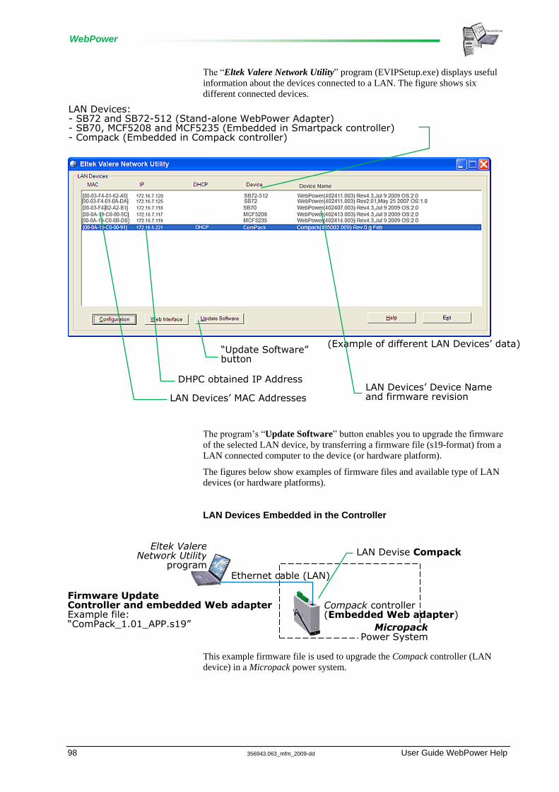
WebPower
98 356943.063_mfm_2009-dd User Guide WebPower Help
The ―Eltek Valere Network Utility‖ program (EVIPSetup.exe) displays useful
information about the devices connected to a LAN. The figure shows six
different connected devices.
The program‘s ―Update Software‖ button enables you to upgrade the firmware
of the selected LAN device, by transferring a firmware file (s19-format) from a
LAN connected computer to the device (or hardware platform).
The figures below show examples of firmware files and available type of LAN
devices (or hardware platforms).
LAN Devices Embedded in the Controller
This example firmware file is used to upgrade the Compack controller (LAN
device) in a Micropack power system.
Micropack Power System
Eltek Valere Network Utility
program Ethernet cable (LAN)
Firmware Update Controller and embedded Web adapter Example file: “ComPack_1.01_APP.s19”
Compack controller (Embedded Web adapter)
LAN Devise Compack
(Example of different LAN Devices’ data)
LAN Devices’ MAC Addresses
DHPC obtained IP Address
“Update Software” button
LAN Devices’ Device Name and firmware revision
LAN Devices: - SB72 and SB72-512 (Stand-alone WebPower Adapter) - SB70, MCF5208 and MCF5235 (Embedded in Smartpack controller) - Compack (Embedded in Compack controller)

WebPower
User Guide WebPower Help 356943.063_mfm_2009-dd 99
Example firmware files used to upgrade the Web adapter (LAN device)
embedded in the controller of a Flatpack2 power system. Each file corresponds
to one of the LAN devices (or hardware platforms).
Stand-alone LAN Devices
This example firmware file is used to upgrade the stand-alone WebPower
Adapter (LAN device) in a Flatpack2 power system.
Example firmware files used to upgrade the stand-alone WebPower Adapter
(LAN device) in an Aeon power system. Each file corresponds to one of the
LAN devices (or hardware platforms).
Eltek Valere Network Utility
program
Ethernet cable (LAN)
Aeon Power System
Aeon Gold controller
WebPower Adapter
(Stand-alone WebPower adapter)
LAN Devise SB72 or SB72-512
Firmware Update WebPower Adapter Example files: “Rev4.2_SB72Webpower_APP.s19” Or “Webpower_SB72-512_43_APP.s19”
Eltek Valere Network Utility
program
Ethernet cable (LAN)
Flatpack2 Power System
(Stand-alone WebPower adapter)
Smartpack controller
WebPower Adapter
LAN Devise SB72
Firmware Update WebPower Adapter Example file: “Rev4.2_SB72Webpower_APP.s19”
Flatpack2 Power System
Smartpack controller (Embedded Web adapter)
LAN Device: SB70 (Smartpack controller, Part 242100.113) or MCF5208 (Smartpack controller, Part 242100.118 HW v2) or MCF5235 (Smartpack controller, Part 242100.118 HW v3)
Firmware Update Embedded Web adapter Example file, respectively: “Rev4.2_SB70Webpower_APP.s19” or “Webpower_MCF5208_43_APP.s19” or “Webpower_MCF5235_43_APP.s19”
Eltek Valere Network Utility
program Ethernet cable (LAN)

WebPower
100 356943.063_mfm_2009-dd User Guide WebPower Help
Example firmware files used to upgrade the stand-alone WebPower Adapter
(LAN device) in a Flatpack power system. Each file corresponds to one of the
LAN devices (or hardware platforms).
WARNING: The upgrade will be aborted, if the selected LAN device (or software platform) and the firmware file do not match.
Alarm Monitors
Alarm monitors are software modules used by the system controller to measure
system internal and external input signals or logical states.
When an alarm monitor is enabled, it compares the measured parameter with
pre-programmed values or limits, and raises an alarm in the event of the
measured parameter reaching one of the limits.
When this event occurs, the alarm monitor stores the event in the Event Log,
initiates an internal action and activates an output group.
Internal pre-programmed actions may be battery current limiting, boost
inhibiting or similar. The generated alarm activates a pre-programmed group
of relay outputs (an alarm output group, AOG).
Eltek Valere Network Utility
program
Ethernet cable (LAN)
Flatpack Power System
MCU controller
WebPower Adapter
(Stand-alone WebPower adapter)
LAN Devise SB72 or SB72-512
Firmware Update WebPower Adapter Example files: “Rev2.01_SB72Webpower_APP.s19” Or “Webpower_SB72-512_43_APP.s19”

WebPower
User Guide WebPower Help 356943.063_mfm_2009-dd 101
The alarm monitors‘ most commonly used configuration parameters are:
(Refer to the ―Alarm Monitor dialog boxes‖ topic in PowerSuite Online Help)
Type of input
The measured Input Signal can be
analogue (e.g. a voltage),
logical (e.g. an open or close contact) and
numeric (e.g. number of rectifiers)
Alarm Monitor activation
You have to Enable the alarm monitor so that it functions
Type of alarm reset
You can select whether the alarm generated by monitor can be reset
manually, or automatically (when the event that caused the alarm is no
longer true)
Hysteresis and Time delay You can enter the hysteresis (lag or delay in response) of the values or
limits, before the alarm monitor raises the alarm.
When the input signal has reached a certain limit or criteria for a certain
period of time, the alarm monitor raises an alarm. This period of time is
called Time delay.
.
For example: A MajorHigh Limit is set to 57.00VDC, with a Hysteresis of
0.10VDC and a Time delay of 2 minutes.
An input signal of 57.08VDC will not cause the alarm monitor to raise an
alarm. The alarm will only be generated when the input signal is over
57.10VDC for a longer period of time than 2 minutes.
Monitored Limits and Events Analogue and numeric alarm monitors compare the measured input with
from one to four user-defined values or limits; two above normal value
(Major High and Minor High) and two below normal value (Minor Low and
Major Low). The type and number of internal actions (events) are usually
defined from factory.
Logical alarm monitors only compare the measured input signal with a
logical state (normally open or close). The user can define the type of event
the monitor activates when the input signal is not in the normal state.
Alarm output groups For each value or limit, you can select which alarm output group (AOG) the
alarm monitor will activate in the event the measured input reaches the
specific limit
Measured Average Value The alarm monitor stores all input signal measurements and performs
average calculations every minute. Then, the monitor continuously displays
the input signal average value, and the period of time the input signal has
been measured. You can restart the monitor‘s average calculations.

WebPower
102 356943.063_mfm_2009-dd User Guide WebPower Help
Measured Peak Value The alarm monitor stores all input signal measurements. Then, the monitor
continuously displays the input signal peak value, since the measurements
started. You can restart the monitor‘s peak value measurements.
In addition, you can configure the alarm monitors with a description of the alarm
monitor and other configuration parameters.
Read also the ―Alarm Monitor dialog boxes‖ topic in PowerSuite Online Help.
Alarm Output Groups
An Alarm Output Group (AOG) is a user defined software assignment that
consists of grouping together all the outputs -- alarm relay outputs and or
latching contactors (LVLD and LVBD) -- that always are activated at the same
time.
The standard Smartpack controller is equipped with 6 alarm relay outputs -- two
on CON1, main card, and four on CON2, in the IO card -- and 2 latching
contactor outputs.
Read also the topic ―System Inputs and Outputs - Overview‖ on page 69, for an
overview of all the power system‘s outputs.
In order to activate the alarm relay outputs and latching contactors (LVLD and
LVBD) in the DC power supply system, you have to assign them to output
groups (AOG).
Output relay assignment and output relay mapping are similar terms, synonyms.
Read also the ―Alarms Overview Outputs tab‖ topic in PowerSuite Online Help.
The DC power supply system uses 20 different alarm output groups (AOG);
18 for assignment of alarm output relays, and 2 or more for assignment of LVD
latching contactors.
Usually, the first seven alarm output groups have alarm relay outputs already
assigned to them from factory (Factory Default Settings).
Typically, alarm output groups 8 through 18 are listed as ―Alarm Group 8‖,
―Alarm Group 9‖… to ―Alarm Group 18‖, but they have no alarm relay outputs
assigned.
Alarm output groups 19 and 20 -- ―LVBD OG‖ and ―LVLD1 OG‖ -- have
usually LVD battery and load latching contactors assigned from factory.

WebPower
User Guide WebPower Help 356943.063_mfm_2009-dd 103
NOTICE: Usually, control units of the type Smartpack and Compack controllers and I/O Monitors (Outdoor) are physically equipped with relay outputs.
The outputs of Smartnode control units are telephone numbers, instead of relay outputs.
The assignment procedure is the same, but you group the phone numbers and assign them to Alarm Output Group. Read also topic “Control Unit Modem Callback Setup tab” in PowerSuite Online Help.
About Eltek Valere
Eltek Valere is a global leader in the development of DC power supply systems,
designed to meet the rapid growth within the industrial and telecommunication
fields, as well as the increasingly stringent reliability requirements.
Energy distribution in industrial, telecommunication and data systems
technology require a guaranteed, uninterruptible power supply. To meet this
demand, Eltek Valere makes in-depth investments in all types of scientific
research, technical development, and experimental mathematical modelling of
thermal characteristics of components and systems.
Compliance to International Standards
A modern power supply system must fulfil various international standards and
regulations, while meeting market requirements. Increased awareness of
Electromagnetic Compatibility (EMC), especially in Europe, has resulted in
Eltek Valere‘s investment in an EMC test laboratory. This laboratory not only
ensures that products comply with relevant standards, it is also utilised
throughout product development. The EMC test laboratory forms part of Eltek
Valere‘s extensive in-house test facility.
Forefront Telecom Power Products
Electronic equipment for data and telecommunications require supply voltages
generated from the mains, as well as from battery-assisted DC voltage. Intensive
development work has produced power supply systems designed to meet both
current and future power requirements, and the development of control and
alarm modules make our power supply systems a market leader. Programmed
functions monitor operating conditions, load and battery bank. Whenever a
problem is detected, the operator will be notified immediately, either via the
telephone network, or via Ethernet. Shutdowns can thus be avoided for critical
applications.
Eltek Valere‘s software expertise is constantly expanding remote communication
capabilities of systems, using standard network protocols.
Eltek Valere accepts no responsibility for any damage or injury to the system,
site or personnel caused by drawings, instructions or procedures not prepared by
Eltek Valere.

WebPower
104 356943.063_mfm_2009-dd User Guide WebPower Help

WebPower
User Guide WebPower Help 356943.063_mfm_2009-dd 105
FAQs
Frequently Asked Questions, FAQs
In this section you find answers to some of the most Frequently Asked Questions
about Eltek Valere‘s DC power systems.
Generic FAQs
PowerSuite and WebPower
Question:
What‘s the difference between PowerSuite and WebPower?
Answer:
PowerSuite is a program to be installed and run on a personal computer, while
WebPower is a graphical user interface (GUI) based on HTML pages that the
controller serve to a standard web browser for viewing. No program installation
required.
WebPower implements the most common configuration task, while PowerSuite
enables full configuration of the power system.
WebPower FAQs
How to Enable Pop-ups in the browser -- Internet Explorer
Question:
How do I enable Pop-ups in the Internet Explorer browser?
Answer:
You must allow the Web browser to show pop-ups from the controller‘s
configuration web pages, as the pages‘ navigation buttons, etc. employ Java
script-based navigation.
Internet Explorer and other Web browsers usually have the Pop-Up Blocker
feature enabled, thus stopping annoying pop-up ads and pop-up windows while
―surfing‖ the Internet.
This topic explains how to configure the Pop-up Blocker to allow pop-ups from
the controller‘s configuration web pages (e.g. IP address <172.16.5.221>), using
Internet Explorer.

WebPower
106 356943.063_mfm_2009-dd User Guide WebPower Help
Carry out the following steps, if the browser‘s Information bar displays that the
Pop-up Blocker has blocked the page, after clicking on one the buttons on the
Power Explorer tool bar:
1. Click on the Information bar
2. Select command ―Always Allow Pop-ups from This Site‖,
from the drop-down menu
3. Click ―Yes‖,
in the ―Allow pop-ups from this site?‖ dialog box
How to Change WebPower’s Default Log in Passwords
Question:
How do I change the default, factory set user name and password of
WebPower‘s ―admin‖ login account?
If you want to create new User Login Accounts, or edit other registered
accounts, then read the topic ―How to Create New User Login Accounts in
WebPower‖ on page 109.
Answer:
To view the controller‘s configuration pages (GUI) in your Web browser and be
able change the ―admin‖ account‘s user name and password, you have to log in
using the ―admin‖ login account.
Following table shows the WebPower‘s default, factory set User Login
Accounts.
Login
Account
User
Name
Password Access
Level
Note
Information Bar (Pop-up blocked…)
Power Explorer Tool Bar (Configuration buttons)
Compack controller’s IP address
Compack controller’s IP address
(Example)

WebPower
User Guide WebPower Help 356943.063_mfm_2009-dd 107
Login
Account
User
Name
Password Access
Level
Note
1 admin admin Factory (or ADMIN) Administration access rights
2 control control Service (or CONTROL) Service access rights
3 status status User (or STATUS) Read only access rights
4 -- -- Factory or Service or User User defined
-- -- -- Factory or Service or User User defined
10 -- -- Factory or Service or User User defined
(Case sensitive passwords)
WARNING: For security reasons, it is advisable to change the default passwords with the passwords of your choice.
Carry out the following steps to change the ―admin‖ account‘s user name and
password:
1. Access the controller’s configuration pages in your Web browser by opening your Web browser (e.g. Internet Explorer) and entering the controller‘s IP address in the browser‘s
address line.
(E.g. <172.16.5.75>; entering ―http://‖ before the address is not necessary).
For more information, read topic Networking the Controller – Access Methods (page 77) on the Functionality
Description section

WebPower
108 356943.063_mfm_2009-dd User Guide WebPower Help
2. Log in with the <admin> account, by clicking on the ―Enter‖ link — in the Web browser, in the middle of the page — and entering <admin> as user
name and <admin> as password (case sensitive).
Or using another login account with Factory Access Level.
Note that the Web browser must have the Pop-ups function enabled, as the configuration web pages employs Java
script navigation.
Read the topic ―How to Enable Pop-ups in the browser -- Internet Explorer‖ on page 105.
(Example of controller’s configuration pages)
Compack Controller’s IP address (Browser’s address line)
“Enter” link
Log in dialog box

WebPower
User Guide WebPower Help 356943.063_mfm_2009-dd 109
3. Change the current user name and password by, — Clicking on the ―System Configuration‖ button (1), on the Power Explorer toolbar
— Clicking on the ―Password‖ tab (2), in the dialog box
— Clicking in the ―Current User Name‖ field (3), and typing the login account‘s new user name
— Selecting the Access Level for the login account; e.g. the ―administrator/factory‖ (4)
— Clicking in the Password fields (5), and typing
the login account‘s current password (case sensitive) and twice the password you want to change to
— Then clicking on the ―Save‖ button (6), to activate the new password
How to Create New User Login Accounts in WebPower
Question:
How do I create new User Login Accounts in WebPower?
Also, how do I edit existing User Login Accounts in WebPower?
Answer:
To view the controller‘s configuration pages (GUI) in your Web browser and be
able to create new User Login Accounts or change registered user names and
passwords, you have to log in using one of the login accounts with Factory (or
ADMIN) Access Level, either the default ―admin‖ account or an already created
account with the Factory (or ADMIN) Access Level.
Following table shows the WebPower‘s default, factory set User Login
Accounts.
Login Account
User Name
Password Access Level
Note
System Configuration
1
2
3
4
5
6
Access Level radio buttons

WebPower
110 356943.063_mfm_2009-dd User Guide WebPower Help
Login Account
User Name
Password Access Level
Note
1 admin admin Factory (or ADMIN) Administration access rights
2 control control Service (or CONTROL) Service access rights
3 status status User (or STATUS) Read only access rights
4 -- -- Factory or Service or User User defined
-- -- -- Factory or Service or User User defined
10 -- -- Factory or Service or User User defined
(Case sensitive passwords)
WARNING: For security reasons, it is advisable to change the default passwords with the passwords of your choice.
Carry out the following steps to create a new account, e.g. the unused login
account number 4:
1. Access the controller’s configuration pages in your Web browser by opening your Web browser (e.g. Internet Explorer) and entering the controller‘s IP address in the browser‘s
address line.
(E.g. <172.16.5.75>; entering ―http://‖ before the address is not necessary).
For more information, read topic Networking the Controller – Access Methods (page 77) on the Functionality
Description section

WebPower
User Guide WebPower Help 356943.063_mfm_2009-dd 111
2. Log in with the <admin> account, by clicking on the ―Enter‖ link — in the Web browser, in the middle of the page — and entering <admin> as user
name and <admin> as password (case sensitive).
Or using another login account with Factory Access Level.
Note that the Web browser must have the Pop-ups function enabled, as the configuration web pages employs Java
script navigation.
Read the topic ―How to Enable Pop-ups in the browser -- Internet Explorer‖ on page 105.
3. Create the new Login Account – or edit existing account – by carrying out the following: — Click on the ―System Configuration‖ button (1), on the Power Explorer toolbar
— Click on the ―Password‖ tab (2), in the dialog box
(Notice the dialog box shows the access level (4) for the login account you have logged in (3))
— Click in the ―Account Overview‖ button (7),
to open a new dialog box with the overview of registered accounts.
(Notice the ―Account Overview‖ button (7) is not displayed, if you are not logged in with an account with Factory
Access Level)
— Click in ―Edit‖ button (8)
for the unused login account that you want to create, e.g. account 4
or for the existing login account that you want to edit.
(A new dialog box for account # 4 is displayed, so you can enter the login data)
— Click in the Current User Name field (9), and type the user name for the new account,
or edit the name of the existing account.
— Select the radio button for the Access Level for the new login account; e.g. the ―control/service‖ (10)
(Example of controller’s configuration pages)
Compack Controller’s IP address (Browser’s address line)
“Enter” link
Log in dialog box

WebPower
112 356943.063_mfm_2009-dd User Guide WebPower Help
— Click in the Password fields (11), and type
the account‘s current password (case sensitive) (not necessary, if creating a new account)
and twice the new password you want to use for this account,
— Then click on the ―Save‖ button (12), to activate the new login account data.
How to Change the Controller’s Device Name
Question:
How do I change the device name of the system controller?
System Configuration
1
8
2
3
4
7
9
10
11
12

WebPower
User Guide WebPower Help 356943.063_mfm_2009-dd 113
Answer:
In order to facilitate identification of the power system when connected a LAN,
it is advisable to log in with the ―admin‖ account and give the system controller
a Device name of your choice.
Carry out the following steps to give a Device name to the controller, using the
controller‘s configuration pages in your Web browser:
1. Access the controller’s configuration pages in your Web browser
by opening your Web browser (e.g. Internet Explorer) and entering the controller‘s IP address in the browser‘s address
line.
(E.g. <169.254.52.133>; entering ―http://‖ before the address is not necessary)
2. Log in with the <admin> account, by clicking on the ―Enter‖ link — in the Web browser, in the middle of the page — and entering <admin> as user
name and <admin> as password (case sensitive) (unless you have previously changed it).
Note that the Web browser must have the Pop-ups function enabled, as the configuration web pages employs Java
script navigation.
Read the topic ―How to Enable Pop-ups in the browser -- Internet Explorer‖ on page 105.
3. Change the controller’s Device Name by,
— Clicking on ―Network Config‖ button, in the Power Explorer‘s toolbar
— Clicking on the ―TCP/IP‖ tab
— Clicking in the Device Name field and entering the Device Name that describes your power system, e.g.
―Micropack System, EV Engine Room, Oslo‖
— Then clicking on the ―Save‖ button, to active the controller‘s new device name
Now the Eltek Valere Network Utility window will display the new device name.
(Example of controller’s configuration pages)
Network Config button (Power Explorer toolbar)
TCP/IP tab
Device Name’s field
Save button

WebPower
114 356943.063_mfm_2009-dd User Guide WebPower Help
How to Check the Status of your LAN Network Card (NIC)
Question:
How to check your NIC‘s IP address, when the computer is running the
MS Windows operating system?
Answer:
In MS Windows, you can always check the IP address, subnet mask, status, etc.
of your personal computer‘s network card (NIC), by opening the ―Network
Connections‖ window and looking at the Detail pane on the left side of the
window.
Notice that you can also get this information by opening a DOS window and
running the command ―IPCONFIG‖.
Carry out the following steps:
1. Open the ―Network Connections‖ window by, — Clicking on the ―Start‖ button, and
— Selecting the options: ―Connect To‖ and ―Show all Connections‖
OR
If this command is not displayed in the computer‘s ―Start‖ menu,
— Clicking on the ―Start‖ button, and
— Selecting the ―Control Panel‖
— Clicking on the ―Network Connections‖ icon
that opens the computer‘s Network Connections window
(Example)
“Show all Connection” command
Start button

WebPower
User Guide WebPower Help 356943.063_mfm_2009-dd 115
2. Find the NIC’s IP address and subnet mask used by the computer by,—
— Selecting the actual network card (NIC),
e.g. ―Local Area Connection 3‖
— Making a note of the IP address and Subnet mask displayed in the Details panel, on the left side of the window.
E.g. IP address: <172.16.5.192>, Subnet mask: <255.255.252.0>
PowerSuite FAQs
Cannot Find the Com Port Number
Question:
Why clicking on the ―Find COM Port #‖ button does not display the COM port
number?
You find the ―Find COM Port #‖ button on dialog box Site Manager dialog box
in PowerSuite Online Help.
Answer:
If the COM port number is not displayed when you click on the ―Find COM Port
#‖ button, the reason could be that the Smartpack USB drivers were not installed
“Network Connection” window
The NIC’s DHCP is enabled: “Obtain an IP address automatically”
“Details” pane, showing IP address, etc (If this pane is not displayed, click on the “Folders” button, on the toolbar, to display it)
“Folders” button
Click on the “Internet Protocol (TCP/IP)” and on the “Properties” button to open the next dialog box.
Selected Network card (NIC) (Local Area Connection 3) The “Details” pane shows the NIC’s IP address, etc Write click on the “Local Area Connection 3” and select “Properties” to open the dialog box.
(Example)

WebPower
116 356943.063_mfm_2009-dd User Guide WebPower Help
in the PC during the PowerSuite program installation, or were installed
incorrectly.
To install the Smartpack USB drivers correctly follow the steps in the topic 2.
Switch the Smartpack ON and connect the USB cable in PowerSuite Online
Help.
Type of Logs in PowerSuite
Question:
What‘s the difference between the types of logs or data records that PowerSuite
displays, and where do I find them?
Answer:
PowerSuite implements following 3 types of logs: (see figure)
Event Log (system related)
A log of power system events automatically registered by the system
controller.
Read more in topic Control System Event Log tab in PowerSuite Online
Help
Data Log (control unit related)
A log of key system data (voltages, current and temperature values)
registered by the system controllers, or by other connected control units
(e.g. I/O Monitor, Mains Monitor) at the intervals specified by
PowerSuite.
Read more in topic Control Unit Data Log tab in PowerSuite Online
Help
Data Logging (system related)
A log of key system data (voltages, current and temperature values) that

WebPower
User Guide WebPower Help 356943.063_mfm_2009-dd 117
PowerSuite registers or saves in a file in your computer.
PowerSuite acquires the key system data by interrogating the system
controller at the specified intervals.
Read more in topic Data Logging dialog box in PowerSuite Online
Help


WebPower
User Guide WebPower Help 356943.063_mfm_2009-dd 119
Glossary of Terms
2AC Power Shelves
2AC Power Shelves (Dual AC feed: 2 AC inputs per shelf, each feeding 2
rectifiers)
4AC Power Shelves
4AC Power Shelves (Single AC feed: 4 AC inputs per shelf, each feeding 1
rectifier)
AC
Alternating Current
Alarm Monitor
Alarm monitors are software modules used by the controller to measure system
internal and external input signals or logical states.
When an alarm monitor is enabled, it compares the measured parameter with
pre-programmed values or limits, and raises an alarm in the event of the
measured parameter reaching one of the limits.
When this event occurs, the alarm monitor stores the event in the Event Log,
initiates an internal action and activates an output group (AOG).
PowerSuite uses 3 types of alarm monitors:
Analogue Alarm Monitors (usually measure voltage or other analogue input
signals),
Numeric Alarm Monitors (count the number of AC phases, rectifiers or other
integers) and
Logical Alarm Monitors (report the state of relay contacts, open or close, or
other similar status)
Read more about Alarm Monitors (page 100) in the Functionality Description
section.
Alarm Monitors
See Alarm monitor
Alarm Output Group
An Alarm Output Group (AOG) is a user defined software assignment that
consists of grouping together all the outputs -- alarm relay outputs and or

WebPower
120 356943.063_mfm_2009-dd User Guide WebPower Help
contactors (LVLD and LVBD); telephone numbers (Smartnode) -- that always
are activated at the same time.
In order to activate the alarm relay outputs, contactors (LVLD and LVBD) or
telephone numbers in the DC power supply system, you have to assign them to
output groups.
Output relay assignment and output relay mapping are similar terms, synonyms.
Read more about Alarm Output Groups (page 102) in the Functionality
Description section.
Alarm Output Groups
See Alarm Output Group
Alarm State
The state of a voltage output or the position of alarm relay contacts when the
output is NOT in normal condition (the output is activated).
Alphanumeric Field
In standard Windows interface, alphanumeric fields in dialogue boxes are areas
that contain text strings or numeric values that the user may change.
Do following to edit the text strings or numeric values in alphanumeric fields:
1. Click inside the field, to insert the cursor in the text or value.
Use your keyboard‘s arrow keys to reposition the cursor
2. Use the keyboard‘s standard editing keys (Delete, Backspace and
typing keys) to edit the text or value
Press the ESC key or click on the dialog box‘s Cancel button or Close
button, if you want to discard the edited changes.
3. Click on the Apply button, in the dialogue box, to save the changes
Accepting or Rejecting Entered Data In standard dialog boxes, clicking on the Apply or the OK buttons will activate
the parameters and data you entered or selected in the box‘s fields.
Clicking on the Cancel button or the Close button – the cross, in the dialog
box‘s title bar – will close the dialog box, and all parameters and data you may
have selected in the box‘s fields will be rejected.
Allowed range of values
If you enter values outside a field‘s allowed range, a red balloon with an
exclamation mark will appear by the field.
Use the mouse to point at the exclamation mark, and a tool tips text box will
indicate the field‘s allowed range.
Alphanumeric Fields
See Alphanumeric field
Ampere-hours (Ah)
A measure of energy that is provided to or drawn from a battery. (A current of
one ampere for one hour equals 1Ah).

WebPower
User Guide WebPower Help 356943.063_mfm_2009-dd 121
Amp-Hour Battery Rating
This is the common rating of a battery. Amp-hour rating of battery capacity is
calculated by multiplying the current (in amperes) by discharge time (in hours).
Amp-hour battery rating is commonly used when describing sealed lead acid
batteries used in Telecom and UPS systems.
For example: a battery which delivers 2 amperes for 20 hours would have a 40
amp-hour battery rating (2 * 20= 40).
Battery Block
Consist of two or more battery cells connected together.
Read more about Battery Functions (page 43) in the Functionality Description
section.
Battery Boost Charging
Battery Boost Charging or Equalized Charging is a fast charge technique used to
reduce recharge time for the batteries and equalize the voltage between
individual cells.
The boost charging voltage should always be higher than the float voltage and
lower than the OVP voltage.
If a reduction in recharge time is required, starting boost charging will increase
the charge voltage and current.
Read more about Battery Functions (page 43) in the Functionality Description
section.
Battery Capacity
By accepted convention worldwide, it is described in "AMPERE HOUR" at the
10-hour rate C10 when discharged at 25°C.
i.e.: a battery is 200 Ah at C10, that is the battery will deliver 20 amps current
for 10 hours to a cut off voltage of for example 1.80 volts per cell.
Battery capacity is affected by the discharge rate, end-voltage, temperature and
age.
Read more about Battery Functions (page 43) in the Functionality Description
section.
Battery Cell
An electrochemical system that converts chemical energy into electrical energy.
Read more about Battery Functions (page 43) in the Functionality Description
section.
Battery Cut-off Voltage
Battery Cut-off Voltage is the volts-per-cell to which a battery may be
discharged safely to maximize battery life.
This data is specified according to the actual discharge load and run time. As a
rule of thumb, high amp loads and short run times will tolerate a lower cut off
voltage, whereas a low amps long run time discharge will require a higher cut off
voltage.
Read more about Battery Functions (page 43) in the Functionality Description
section.

WebPower
122 356943.063_mfm_2009-dd User Guide WebPower Help
Battery Cycle
A full charge followed by a full discharge (or the other way around). Cycle life
is measured by the amount of times a battery may be charged and discharged.
Every time a battery is charged and discharged, it uses one cycle. Cycle life is
very important in battery applications such as laptop batteries and emergency
light batteries. A NiCad battery has a cycle life of 500-1000 or more cycles.
Read more about Battery Functions (page 43) in the Functionality Description
section.
Battery Definition Table
It is also called Discharge Table, which indicates a battery‘s constant current
discharge performance data.
A battery model for Telecom applications can be selected by referring to a
constant current discharge table for a specific period of time, to a specified end-
of-discharge voltage and temperature.
Battery Discharge Characteristic
The discharge capacity of a lead acid battery varies, and is dependant on the
discharge current.
A battery could use a rate at the 10 hour rate. i.e. the capacity of the battery at 10
hours discharged to an end voltage of 1.80 Vpc (volts per cell) at a temperature
of 25°C.
Battery Float Voltage
A constant voltage applied to a battery to maintain the battery capacity.
Read more about Battery Functions (page 43) in the Functionality Description
section.
Boost Mode
Boost Mode is one of the PowerSuite‘s operation modes, where the rectifiers
charge the batteries much faster than while in Float Mode.
Boost Voltage
Indicates the output voltage during fast battery recharge (battery boost charging).
Increased charge voltage will reduce the required recharge time.
Browser
Short for Web browser, a software application used to locate and display Web
pages. The two most popular browsers are Microsoft Internet Explorer and
Firefox. Both of these are graphical browsers, meaning that they can display
graphics as well as text. In addition, most modern browsers can present
multimedia information, including sound and video, though they require plug-ins
for some formats.
CAN Bus
Controller Area Network (CAN or CAN bus) is a serial protocol utilized for
communication between Eltek Valere‘s rectifiers, controllers and other control

WebPower
User Guide WebPower Help 356943.063_mfm_2009-dd 123
units. The protocol is used in DC power systems that use the Smartpack
controller, the Compack controller and in Aeon systems.
The CAN bus standard was originally designed to allow microcontrollers and
devices to communicate with each other without a host computer.
The CAN specification defines the Data Link Layer, while ISO 11898 defines
the Physical Layer.
The CAN bus is a 2-wire interface running over either a Shielded Twisted Pair
(STP), Un-shielded Twisted Pair (UTP), or Ribbon cable. Each node uses a Male
9-pin D connector.
Capacity
The electrical energy content of a battery as expressed in ampere-hours.
Capacity is the total number of ampere-hours or watt-hours that can be
withdrawn from a fully charged cell or battery under specific condition of
discharge. The capacity is measured by observing the time it takes to discharge a
battery at a constant current until a specified cut-off voltage is reached.
See also ―Battery Capacity‖ on page Error! Bookmark not defined.
Cell mismatch
Cells within a battery pack containing different capacity and voltage levels.
Cell reversal
The stronger cells of a battery (several cells connected in series) impose a
voltage of reverse polarity across a weaker cell during a deep discharge.
Charge
The process of replenishing or replacing the electrical charge in a rechargeable
cell or battery.
Compack
A versatile microprocessor based controller for monitoring Micropack DC power
supply systems. The controller is designed for DIN rail mounting.
Control Unit
See Control Units.
Control Units
The control system -- in Eltek Valere DC power systems – consists of control
units or hardware devices connected to the system‘s CAN bus.
Several types of control units may be connected, such as:
Smartpack controllers
Compack controllers
Smartnode control units
Battery Monitors
Load Monitors

WebPower
124 356943.063_mfm_2009-dd User Guide WebPower Help
I/O Monitors
Mains Monitors
Other CAN nodes
C-rate
Unit by which charge and discharge times are scaled. A battery rated at
1000mAh provides 1000mA for one hour if discharged at 1C. A discharge of 1C
draws a current equal to the rated capacity. The same battery discharged at 0.5C
would provide 500mA for two hours.
Critical Condition
A DC power system‘s state caused when one or several serious circumstances
occur. Usually, the DC power supply system is in critical condition when the
battery bank is the only supply source (negative battery current).
Using PowerSuite, you can configure which circumstances (monitors in alarm)
the DC power system has to encounter for the system to be in critical condition.
Crossover Cable
An Ethernet crossover cable is a type of Ethernet cable used to connect
computing devices together directly where they would normally be connected
via a network switch, hub or router, such as directly connecting two personal
computers via their network adapters.
The 10BASE-T and 100BASE-TX Ethernet standards use one wire pair for
transmission in each direction. The Tx+ line from each device connects to the tip
conductor, and the Tx- line is connected to the ring. This requires that the
transmit pair of each device be connected to the receive pair of the device on the
other end. When a terminal device is connected to a switch or hub, this crossover
is done internally in the switch or hub. A standard straight through cable is used
for this purpose where each pin of the connector on one end is connected to the
corresponding pin on the other connector.
Current-limiting chargers
A charger that keeps the charge current constant during the charge process but
allows the voltage to fluctuate.
Cycle life
The number of cycles a battery provides before it is no longer usable. (A battery
is considered non-usable if its nominal capacity falls below 60 to 80 percent).
DC
Direct Current
DC Power Supply Systems
Eltek Valere’s modern ranges of DC power supply systems using the Smartpack
or the Compack as system controllers.
The Smartpack-based systems use the Smartpack controller and Flatpack2
rectifiers or Powerpack three-phase rectifier modules as their building blocks.

WebPower
User Guide WebPower Help 356943.063_mfm_2009-dd 125
In addition to these modules, a system incorporates AC distribution for the
rectifier inputs and DC distribution, batteries, LVD options, etc.
The Compack-based systems use the Compack controller, Micropack rectifiers
and Battery and Load Distribution modules as their building blocks.
All the Micropack building blocks are designed for DIN rail mounting.
DC Power System
See DC Power Supply Systems
DC Power Systems
See DC Power Supply Systems
Delta Voltage
Delta voltage is an absolute calculated value that represents how well balanced
the battery blocks that form a string are. PowerSuite uses this expression when
calculating battery symmetry.
Delta voltage (Vdelta) is the difference between the calculated and the measured
voltages, e.g. (Vbattery / 2) - Vmeasured = | Vdelta |
A Delta voltage of 0V indicates a completely balanced battery string.
DHCP
Dynamic Host Configuration Protocol (DHCP) is a network application protocol
used by devices (DHCP clients) to obtain configuration information for
operation in an Internet Protocol network. This protocol reduces system
administration workload, allowing devices to be added to the network with little
or no manual intervention.
Drop-down List
In standard Windows interface, a drop-down list in a dialogue box is a field
containing a down-arrow button at the field‘s right side, which displays a list of
text strings or numeric values that the user may select from.
When the list is up, the field displays the selected value.
Do following to select values form the drop-down list:
1. Click on the down-arrow button, to display the list with available
values
2. If the list is longer than displayed, click on the list’s scroll bar buttons
(up or down buttons) to find the value you want to select
3. Click on the value you want to select.
The drop-down list disappears and the selected value is displayed
Accepting or Rejecting Entered Data In standard dialog boxes, clicking on the Apply or the OK buttons will activate
the parameters and data you entered or selected in the box‘s fields.
Clicking on the Cancel button or the Close button – the cross, in the dialog
box‘s title bar – will close the dialog box, and all parameters and data you may
have selected in the box‘s fields will be rejected.

WebPower
126 356943.063_mfm_2009-dd User Guide WebPower Help
Drop-down Lists
See Drop-down List
Eltek Valere
Eltek Valere is a global corporation that secures worldwide communication by
providing critical power solutions for telecom infrastructure. The company is the
result of the acquisition of Valere Power by Eltek Energy.
Eltek Valere Network Utility
Simple Windows-based utility program (EVIPSetup.exe) that needs no software
installation
It is used to display the Smartpack and Compack controller‘s network
parameters, when connected to an Ethernet LAN.
Also, it enables changing the controller‘s IP address, configuring the controller
via a standard Web browser and upgrading the controller‘s firmware.
End-of-Discharge Voltage
The voltage point to which a battery can be discharged is a function of the
discharge rate. The Recommended End-Voltage Point (REVP) is the voltage at
which a battery should be disconnected from the load.
Discharging the battery below the REVP, or leaving the battery connected to a
load in a discharged state will ―over-discharge‖ the battery, and may impair its
ability to accept charge.
Energy
Voltage multiplied by current expressed in watts.
Equalizing Charge
With time, the charge levels of individual cells of a large battery tend to become
slightly unbalanced. The equalizing charge applies an elevated charge voltage
for a few hours to balance the cells. Used mainly for large lead acid cells.
Ethernet
Local Area Network technology. Ethernet provides data transfer using a
baseband (single-channel) communication technique. Ethernet uses carrier sense
multiple access collision detection (CSMA/CD) that prevents network failures
when two devices attempt to access the network at the same time. A 10/100
Ethernet port supports 10BASE-T and 100BASE-TX.
See also Ethernet, more…
Ethernet, more…
Ethernet is a large, diverse family of frame-based computer networking
technologies that operates at many speeds for local area networks (LANs).
It defines a number of wiring and signaling standards for the physical layer,
through means of network access at the Media Access Control (MAC)/Data Link
Layer, and a common addressing format.

WebPower
User Guide WebPower Help 356943.063_mfm_2009-dd 127
Ethernet has been standardized as IEEE 802.3. The combination of the twisted
pair versions of Ethernet for connecting end systems to the network with the
fiber optic versions for site backbones become the most widespread wired LAN
technology in use from the 1990s to the present, largely replacing competing
LAN standards such as coaxial cable Ethernet, token ring, FDDI, and ARCNET.
In recent years, Wi-Fi, the wireless LAN standardized by IEEE 802.11, has been
used instead of Ethernet for many home and small office networks and in
addition to Ethernet in larger installations.
Event
See Events
Events
In Eltek Valere DC power systems, events are system internal actions used in
PowerSuite alarm monitors.
Alarm monitors measure system internal and external input signals or logical
states, and compare the measured parameter with pre-programmed values or
limits. The alarm monitors raise an alarm in the event of the measured
parameter reaching one of the limits.
EVIPSetup.exe
See Eltek Valere Network Utility Program
Firmware
Firmware is software stored permanently on ROM or PROM chips. It can also
be electrically erased and reprogrammed (flashed) when stored in EEPROM
chips.
Flatpack
Eltek Valere’s range of DC power supply systems, using the MCU controller and
Flatpack rectifiers as their building blocks. Though the range has been installed
worldwide in a variety of system solutions, and it is now replaced by the
compact Flatpack2 range.
Flatpack2
Eltek Valere’s modern range of DC power supply systems, using the Smartpack
controller and Flatpack2 rectifiers as their building blocks. The range covers
integrated, cabinetized and outdoor system solutions.
Float charge
Similar to trickle charge. Compensates for the self-discharge on a lead acid
battery.
Float Mode
Float Mode is one of the PowerSuite‘s operation modes, where the rectifiers
charge the batteries enough to compensate for self-discharging.

WebPower
128 356943.063_mfm_2009-dd User Guide WebPower Help
FTP Server
Trivial File Transfer Protocol Server (TFTP). A host to provide services
according to TFTP; a TCP/IP standard protocol for file transfer with minimal
capability and overhead depending on UDP for ts datagram delivery service.
GUI
Pronounced GOO-ee. Acronym for graphical user interface. A program interface
that takes advantage of the computer's graphics capabilities to make the program
easier to use. Well-designed graphical user interfaces can free the user from
learning complex command languages. On the other hand, many users find that
they work more effectively with a command-driven interface, especially if they
already know the command language.
HTTP
Hypertext Transfer Protocol (HTTP) is a communications protocol for the
transfer of information on intranets and the World Wide Web. Its original
purpose was to provide a way to publish and retrieve hypertext pages over the
Internet.
HUB
A common connection point for devices in a network. Hubs are commonly used
to connect segments of a LAN. A hub contains multiple ports. When a packet
arrives at one port, it is copied to the other ports so that all segments of the LAN
can see all packets.
I/O
Short for Input /Output. The term I/O is used to describe any program, operation
or device that transfers data to or from a computer and to or from a peripheral
device. Every transfer is an output from one device and an input into another.
InstallShield Wizard
A graphical screen interface that guides you through the steps required to install
a Windows based software application, such as PowerSuite.
InstallShield for Windows Installer by InstallShield Software Corporation.
The InstallShield Software Corporation creates products that distribute and
manage digital content by using packaged applications.
IP Address
The Internet Protocol Address
IP version 4 addresses (IPv4) uses 32-bit (4-byte) addresses, which limits the
address space to 4,294,967,296 possible unique addresses. However, IPv4
reserves some addresses for special purposes such as private networks (~18
million addresses) or multicast addresses (~270 million addresses).
IPv4 addresses are usually represented in dot-decimal notation (four numbers,
each ranging from 0 to 255, separated by dots, e.g. 208.77.188.166). Each part
represents 8 bits of the address, and is therefore called an octet.

WebPower
User Guide WebPower Help 356943.063_mfm_2009-dd 129
LAN
Local Area Network
A local area network is a computer network covering a small physical area, like
a home, office, or small group of buildings, such as a school, or an airport.
Current LANs are most likely to be based on Ethernet technology.
Latching Contactor
Magnetically latching contactor
The coil of latching contactors is not energized in any state. They change state
from open to close, or vice versa, when a reversed pulse voltage is applied to its
coil.
Latching Contactors
See Latching Contactor
Local Area Network
A local area network is a computer network covering a small geographic area,
like a home, office, or group of buildings.
Current LANs are most likely to be based on switched IEEE 802.3 Ethernet
technology, running at 10, 100 or 1,000 Mbit/s, or on IEEE 802.11 Wi-Fi
technology.
Each node or computer in the LAN has its own computing power but it can also
access other devices on the LAN subject to the permissions it has been allowed.
These could include data, processing power, and the ability to communicate or
chat with other users in the network.
LVBD
Low Voltage Battery Disconnect contactor
System internal latching contactor that disconnects the battery bank from the
load, when a certain voltage limit is reached or other battery critical events
occur.

WebPower
130 356943.063_mfm_2009-dd User Guide WebPower Help
LVD
Low Voltage Disconnect contactor
System internal latching contactor that disconnects the batteries from the load or
the output power from non-priority load, when a certain voltage limit is reached
or a certain event occurs.
LVLD
Low Voltage Load Disconnect contactor
System internal latching contactor that disconnects the output power from non-
priority load, when a certain voltage limit is reached or the mains input fails or
other events occur.
MAC Address
Media Access Control Address
Every Ethernet network card has a unique 48-bit serial number called a MAC
address, which is stored in ROM carried on the card. Every computer on an
Ethernet network must have a card with a unique MAC address. Normally it is
safe to assume that no two network cards will share the same address, because
card vendors purchase blocks of addresses from the Institute of Electrical and
Electronics Engineers (IEEE) and assign a unique address to each card at the
time of manufacture.
MCB
Miniature Circuit Breaker
MIB
Management Information Base, a database of objects that can be monitored by a
network management system. SNMP uses standardized MIB formats that allows
any SNMP tools to monitor any device defined by a MIB
Micropack
Eltek Valere’s modern range of DC power supply systems using the Compack
controller, Micropack rectifiers, Battery Distribution Base and Load Distribution
Bases as their building blocks. All units are designed for DIN rail mounting.
The range covers low power solutions in telecom and industrial applications.
Mini Hub
A common connection point for devices in a network. Hubs are commonly used
to connect segments of a LAN. A hub contains multiple ports. When a packet
arrives at one port, it is copied to the other ports so that all segments of the LAN
can see all packets
Modem
A modem (from modulate and demodulate) is a device that modulates an analog
carrier signal to encode digital information, and also demodulates such a carrier
signal to decode the transmitted information.

WebPower
User Guide WebPower Help 356943.063_mfm_2009-dd 131
NC-C-NO
Acronym for Normally Closed, Common and Normally Open. The expression
refers to the position of 3 relay contacts, when the relay coil is de-energized.
When the relay coil is energized, the NC-C contacts open, and the C-NO
contacts close.
Negative DC Distribution
It is usually implemented in 48V and 60V DC power supply systems, which
have the DC distribution on the negative output (-48VDC or -60VDC), and
the positive on a Common Positive DC Output Rail (0V).
NIC
Network Interface Controller.
A network card, network adapter, network interface controller, network interface
card, or LAN adapter is a computer hardware component designed to allow
computers to communicate over a computer network. It is both an OSI layer 1
(physical layer) and layer 2 (data link layer) device, as it provides physical
access to a networking medium and provides a low-level addressing system
through the use of MAC addresses. It allows users to connect to each other either
by using cables or wirelessly.
NMS
Network Management Station -An SNMP Manager application which interfaces
with the SNMP Agent and provides communication capabilities through
standard SNMP messaging commands (SET, GET). The NMS also serves to
collect SNMP TRAP events.
A Network Management System (NMS) is a combination of hardware and
software used to monitor and administer a network.
NO-C-NC
Acronym for Normally Open, Common and Normally Closed. The expression
refers to the position of 3 relay contacts, when the relay coil is de-energized.
When the relay coil is energized, the NO-C contacts close, and the C-NC
contacts open.
Nominal voltage
The cell voltage that is accepted as an industrial standard.
Non-Priority Load
Telecom equipment or similar supplied from the DC power system‘s load output
circuits. The equipment‘s continuous operation is NOT essential, and has low
backup priority during Mains outages.
Generally, the DC power system temporally stops supplying this equipment
during a system critical condition, or when the equipment‘s backup leasing time
has expired.

WebPower
132 356943.063_mfm_2009-dd User Guide WebPower Help
Normal Condition
A DC power system‘s state when no serious circumstances occur. Usually, the
DC power supply system is in normal condition when no critical condition
occurs.
Normal State
The state of a voltage output or the position of alarm relay contacts when the
output is in normal condition (not activated).
Overcharge
Charging a battery after it reaches full charge. On overcharge, the battery can no
longer absorb charge and the battery heats up.
OVP
Over Voltage Protection
OVS
Over Voltage Shutdown
When the output voltage of a malfunctioning rectifier reaches a certain limit, the
system automatically shuts down to prevent damages.
pComm
RS232 serial protocol used by Eltek Valere‘s controllers for communication with
computers, modems, WebPower adapters and other equipment.
Pop-up
A window that suddenly appears (pops up) when you select an option with a
mouse or press a special function key. Usually, the pop-up window contains a
menu of commands and stays on the screen only until you select one of the
commands. It then disappears. A special kind of pop-up window is a pull-down
menu, which appears just below the item you selected, as if you had pulled it
down.
Positive DC Distribution
It is usually implemented in 24V DC power supply systems, which have the DC
distribution on the positive output (24VDC), and the negative on a Common
Negative DC Output Rail (0V).
Powerpack
Eltek Valere’s modern range of large three-phase DC power supply systems,
using the Smartpack controller and Powerpack three-phase rectifier modules as
their building blocks.

WebPower
User Guide WebPower Help 356943.063_mfm_2009-dd 133
PowerSuite
PC application used to configure and operate Micropack, Minipack, Flatpack2
and Powerpack DC power supply systems. The program is to be run on
computers using the MS Windows operating systems.
Priority Load
Very important telecom equipment or similar supplied from the DC power
system‘s load output circuits. The equipment‘s continuous operation is essential
and has high backup priority during Mains outages.
PSS
Power Supply System
REVP
Recommended End-Voltage Point. Read also ―End-of-Discharge Voltage‖ on
page Error! Bookmark not defined.
RJ-45
Short for Registered Jack-45, an eight-wire connector used commonly to connect
computers onto local area networks (LAN), especially Ethernets. RJ-45
connectors look similar to the ubiquitous RJ-11 connectors used for connecting
telephone equipment, but they are somewhat wider.
RS232
Serial communication bus or communication port
RS485
Serial communication bus or communication port
Shunt
A current shunt is usually a resistor of accurately-known very small resistance
that allows the measurement of current values too large to be directly measured
by a particular ammeter.
The current shunt is placed in series with the load, so that nearly all of the
current to be measured will flow through it. The voltage drop across the shunt is
proportional to the current flowing through it, and since its resistance is known, a
millivolt meter connected across the shunt can be scaled to directly read the
current value.
Shunts are rated by maximum current and voltage drop at that current, for
example, a 500A/75mV shunt would have a resistance of 0.15 milliohms, a
maximum allowable current of 500 amps and at that current the voltage drop
would be 75 millivolts.
By convention, most shunts are designed to drop 75mV when operating at their
full rated current and most "ammeters" are actually designed as voltmeters that
reach full-scale deflection at 75mV.

WebPower
134 356943.063_mfm_2009-dd User Guide WebPower Help
Smartpack
A versatile microprocessor based controller for monitoring Minipack, Flatpack2
and Powerpack DC power supply systems in a network.
SNMP
Simple Network Management Protocol, a set of protocols for managing complex
networks. The first versions of SNMP were developed in the early 80s. SNMP
works by sending messages, called protocol data units (PDUs), to different parts
of a network. SNMP-compliant devices, called agents, store data about
themselves in Management Information Bases (MIBs) and return this data to the
SNMP requesters.
SNMP Agent
An SNMP-compliant device that stores data about itself in Management
Information Bases (MIBs) and return this data to the SNMP requesters.
Software
Software are programs for directing the operation of computers,
microprocessors, controllers, etc. or for processing electronic data.
TCP/IP
Transmission Control Protocol/Internet Protocol
A protocol suite used by more than 15 million users with a UNIX association
and widely used to link computers of different kinds.
The Internet Protocol Suite (commonly known as TCP/IP) is the set of
communications protocols used for the Internet and other similar networks. It is
named from two of the most important protocols in it: the Transmission Control
Protocol (TCP) and the Internet Protocol (IP), which were the first two
networking protocols defined in this standard.
Test Mode
Test Mode is one of the PowerSuite‘s operation modes, where the system
controller is performing a specific preprogrammed test of the battery bank.
The Cycle
A process consisting of a single charge and discharge of a rechargeable battery.
Trickle charge
Maintenance charge to compensate for the battery's self-discharge.
Tunnelling Protocol
The term tunnelling protocol is used to describe when one network protocol
called the payload protocol is encapsulated within a different delivery protocol.

WebPower
User Guide WebPower Help 356943.063_mfm_2009-dd 135
UDP
The User Datagram Protocol (UDP) is one of the core members of the Internet
Protocol Suite, the set of network protocols used for the Internet. With UDP,
computer applications can send messages, sometimes known as datagrams, to
other hosts on an Internet Protocol (IP) network without requiring prior
communications to set up special transmission channels or data paths. UDP is
sometimes called the Universal Datagram Protocol.
URL
URL is an abbreviation of Uniform Resource Locator, the global address of
documents and other resources on the World Wide Web.
The first part of the address is called a protocol identifier (ftp, http, etc.) and it
indicates what protocol to use. The second part is called a resource name and it
specifies the IP address or the domain name where the resource is located. The
protocol identifier and the resource name are separated by a colon and two
forward slashes. For example: ftp://sw.eltekenergy.com/powersuite.exe and
http://www.eltekvalere.com/index.html
USB
Universal Serial Bus is a serial bus standard to interface devices to a host
computer. USB was designed to allow many peripherals to be connected using a
single standardized interface socket and to improve plug and play capabilities by
allowing hot swapping, that is, by allowing devices to be connected and
disconnected without rebooting the computer or turning off the device. Other
convenient features include providing power to low-consumption devices
without the need for an external power supply and allowing many devices to be
used without requiring manufacturer specific, individual device drivers to be
installed.
VPN
A virtual private network (VPN) is a computer network in which some of the
links between nodes are carried by open connections or virtual circuits in some
larger network (e.g., the Internet) as opposed to running across a single private
network. The link-layer protocols of the virtual network are said to be tunnelled
through the larger network. One common application is secure communications
through the public Internet, but a VPN need not have explicit security features,
such as authentication or content encryption. VPNs, for example, can be used to
separate the traffic of different user communities over an underlying network
with strong security features.
WAN
Wide Area Network is a computer network that covers a broad area (i.e., any
network whose communications links cross metropolitan, regional, or national
boundaries [1]). Less formally, a WAN is a network that uses routers and public
communications links [1]. Contrast with personal area networks (PANs), local
area networks (LANs), campus area networks (CANs), or metropolitan area
networks (MANs) are usually limited to a room, building, campus or specific
metropolitan area (e.g., a city) respectively. The largest and most well-known
example of a WAN is the Internet.

WebPower
136 356943.063_mfm_2009-dd User Guide WebPower Help
WebPower
A common name for the firmware installed in Eltek Valere‘s controllers --
Compack and Smartpack, web option – and in the external WebPower adapter
module. The firmware provides a communication protocol translator, a physical
layer conversion and Web server software.
WebPower translates the controller‘s internal protocol into the HTTP protocol
over TCP/IP, used to communicate in an Ethernet network, LAN, WAN, VPN or
even across the Internet.
The WebPower firmware provides a platform-independent graphical user
interface (GUI), employed to configure and operate Micropack, Minipack,
Flatpack2 and Powerpack DC power supply systems using a standard Web
browser.
In addition, WebPower provides an SNMP Agent, allowing Eltek Valere DC
power systems to be interoperable with SNMP enterprise management solutions,
which are commonly in use within the Telecommunications industry.

WebPower
User Guide WebPower Help Index 137
Index
"
"BatteryLifeTime" Monitor Calculations 62
A
About AC, DC Earthing Systems 32
About Eltek Valere 103
About Eltek Valere's SNMP MIB Files 92
About the WebPower Firmware 3
Accessing the Controller and Logging In to
WebPower 5
Active Alarm Groups web page 25
Alarm Messages, (Log) 36
Alarm Monitors 100
Alarm Output Groups 102
Alarm Reset 34
All Available System Inputs & Outputs 71
Answer: 105, 106, 109, 113, 114, 115, 116
Available Inputs and Outputs 73, 75, 76, 77
Available System Alarm Relay Outputs 70
Available System Current Sense Inputs 70
Available System Fan Control Inputs & Outputs 70
Available System Fuse Monitoring Inputs 70
Available System Programmable Inputs 71
Available System Temperature Sense Inputs 71
Available System Voltage Inputs 71
B
Battery 29
Battery Bank nn subpage 29
Battery Banks, Strings and Blocks 43
Battery Boost subpage 29
Battery Charging Current Limitation 61
Battery Current Calibration 38
Battery Functions 43
Battery Symmetry Calculations 49
Battery Symmetry Measurements 46
Battery Symmetry Voltage Calibration 39
Battery Tables 52
Battery Temperature Calibration 40
Battery Temperature Levels ~ "BatteryLifeTime"
monitor 62
Battery Test Log subpage 16
Battery Test Results web page 16
Battery Test Start Methods 56
Battery Test subpage 29
Battery Tests 54
Battery Voltage Calibration 39
Battery web page 29
Block Diagram 72, 74
Block Measurement Calculation -- Example 50
C
CAN Bus Address Range -- Control Units 67
CAN bus Addressing 66
CAN bus Termination 32
Cannot Find the Com Port Number 115
Compack Controller 4
Compack nn subpage (inputs) 30
Compack nn subpage (outputs) 30
Compliance to International Standards 103
Configuration of Critical Condition 34
Configuration subpage (battery) 29
Configuration subpage (rectifiers) 29
Control System 30
Control System Functions 66
Control Units, Controllers, CAN Nodes, etc 72
Controller Access -- Via Ethernet LAN 79
Controller Access -- Via Stand-alone PC 82
Controller's Default IP Address 78
D
Discharge Performance Data 53
Discontinuance Battery Test 58
Discontinuance Battery Test Calculations 58
E
Effect of Temperature on Battery Capacity 60
Effect of Temperature on Charging Voltage 60
eMail tab 19
Event Log web page 18
Example -- NMS Configuration 93
Excessive Battery Charging and Discharging 61
F
Firmware Upgrade 94
Firmware Upgrade - Compack Controller 96
Firmware Upgrade - Smartpack Controller 95
Firmware Upgrade - Smartpack's Embedded Web
Adapter 97
Firmware Upgrade - Stand-alone WebPower Adapter
97
Forefront Telecom Power Products 103
Frequently Asked Questions, FAQs 105
From Configuration Web Pages 35, 36, 42
From PowerSuite 35, 36, 42
From the Smartpack Controller's Front 34, 35, 36, 42
Functionality Overview 31

WebPower
138 356943.063_mfm_2009-dd User Guide WebPower Help
G
Generic FAQs 105
Getting Started 3
H
Hardware Assignment -- Control Units 67
Hardware Requirements 58
Help web page 26
How Does It Function 58
How to Calibrate 37
How to Change the Controller's Device Name 112
How to Change WebPower's Default Log in
Passwords 106
How to Check the Status of your LAN Network Card
(NIC) 114
How to Create New User Login Accounts in
WebPower 109
How to Enable Pop-ups in the browser -- Internet
Explorer 105
How to Select Tables 53
How to Use or Save the Table 53
I
In Short 79, 83, 88
Inputs 30
Inputs web page 30
L
Load 29
Load Bank nn subpage 29
Load Current Calculation 66
Load Functions 65
Load web page 29
LVBD - Battery Protection 63
LVBD subpage 29
LVLD ~ Non-Priority Load Disconnection 65
M
Mains 28
Mains Functions 40
Mains Phase Assignment versus Rectifier ID 40
Mains web page 28
Map Coordinates tab 12
Mid-point Measurement Calculation -- Example 49
Monitoring -- via Network Management System 87
More Detailed 80, 83
More Detailed - Controller SNMP Configuration 89
N
Network Config web page 19
Networking the Controller - Access Methods 77
O
Online Help Files tab 24
Outputs 30
Outputs web page 30
Overview Battery Measurements 45
Overview Firmware Files and LAN Devices 97
P
Password tab 14
Plug-and-Play Rectifiers 41
Power Explorer pane (1) 8
Power Explorer Pane web pages 28
Power Summary (3) pane 9
Power System 28
Power System Configuration & Monitoring -
Methods 86
Power System Functions 31
Power System web page 28
Power System's Operation Mode 33
PowerSuite and WebPower 105
PowerSuite FAQs 115
R
Rectifier Functions 40
Rectifier Information 41
Rectifier Status - Alarm Levels 43
Rectifiers 28
Rectifiers web page 29
Requirements 79, 82, 88
Resetting the Number of Rectifiers 41
S
Smartpack Controller 4
Smartpack Options 74
SNMP tab 22
Software Assignment -- Rectifiers 67
Symmetry in 24V Systems 48
Symmetry in 48V Systems 46
Symmetry Measurements during Discharge Mode 48
System Calibration 36
System Configuration web page 12
System Inputs and Outputs - Overview 69
System Voltage Levels web page 11
System Voltages 34
T
TCP/IP tab 21
Temperature Compensated Charging 59
Temperature Compensated Charging Equation 59
The Battery Monitor Control Unit - Overview 76
The Compack Controller - Overview 74
The I/O Monitor Control Unit - Overview 77
The Load Monitor Control Unit - Overview 76
The Smartnode Control Unit - Overview 75
The Smartpack Controller - Overview 72
The Working Area (2) 8
Toolbar - Internet Browser (5) 10
Toolbar - WebPower (4) 10

WebPower
User Guide WebPower Help Index 139
Toolbar web pages 11
Type of Logs in PowerSuite 116
Types of Battery Tests 55
U
Understanding the WebPower Interface 7
Using WebPower 11
W
Web Address Line - WebPower (6) 10
WebPower FAQs 105
WebPower Home Page 7
Welcome to WebPower 1
What to Calibrate 36


www.eltekvalere.com
Headquarters:Eltek Valere
Gråterudv. 8, Pb 2340 Strømsø, 3003 Drammen, NorwayPhone: +47 32 20 32 00 Fax: +47 32 20 32 10


