64
Wedge Shear Testing of Soils An insufficiently utilized new technique Prof. Dr. Türker Mirata m [email protected]
| Date post: | 22-Dec-2015 |
| Category: |
Documents |
| Upload: | loreen-horn |
| View: | 222 times |
| Download: | 3 times |

Wedge Shear Testing of SoilsAn insufficiently utilized new technique
Prof. Dr. Türker [email protected]
© Türker Mirata 2
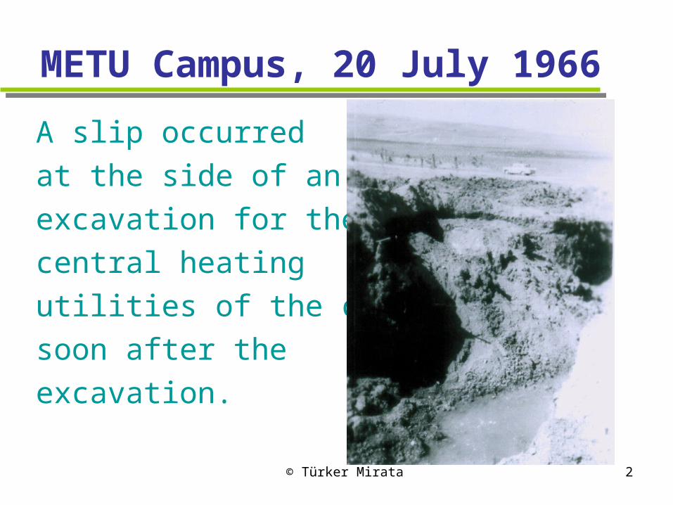
METU Campus, 20 July 1966
A slip occurred
at the side of an
excavation for the
central heating
utilities of the campus
soon after the
excavation.
© Türker Mirata 3
This raised the QUESTION
Can one not devise a relatively simple test for pedicting, with fair accuracy, the safety of such slopes in stiff, fissured, unsaturated clays like the Ankara Clay?
The following 24 years saw to the development of three different versions of a testing technique which not only answers the above but also facilitates the shear testing of gravels and crushed rock.
© Türker Mirata 4
1. The in situ wedge shear test (iswest)
Suitable especially for unsaturated, stiff fissured and/or stony clays
Tried successfully on three slips in the Ankara Clay

© Türker Mirata 5
Principle of the iswest

© Türker Mirata 6
Loading mechanism

© Türker Mirata 7
Loading possible in any direction
© Türker Mirata 8
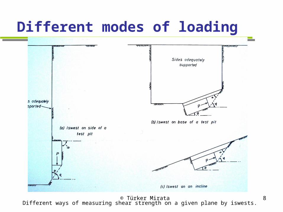
Different modes of loading
Different ways of measuring shear strength on a given plane by iswests.

© Türker Mirata 9
Six iswests carried out at Site C/1
7-23 June 1971; iswests in pit 9m from 1968 slip
Note inclination of shear plane in different iswests, conforming with the failure surface in the actual slip.
© Türker Mirata 10
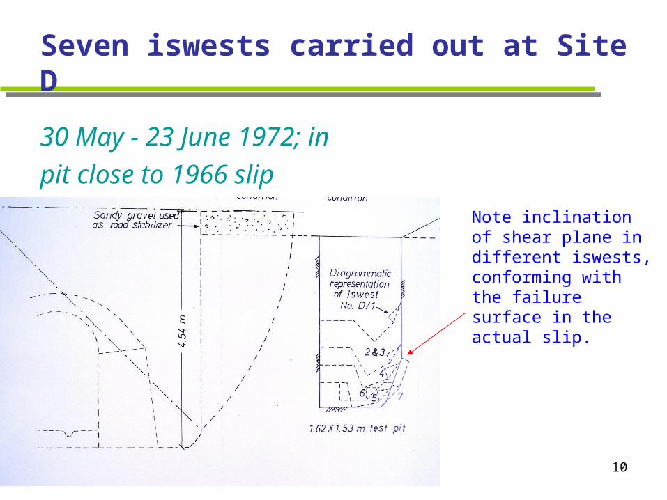
Seven iswests carried out at Site D
30 May - 23 June 1972; in
pit close to 1966 slip
Note inclination of shear plane in different iswests, conforming with the failure surface in the actual slip.
© Türker Mirata 11
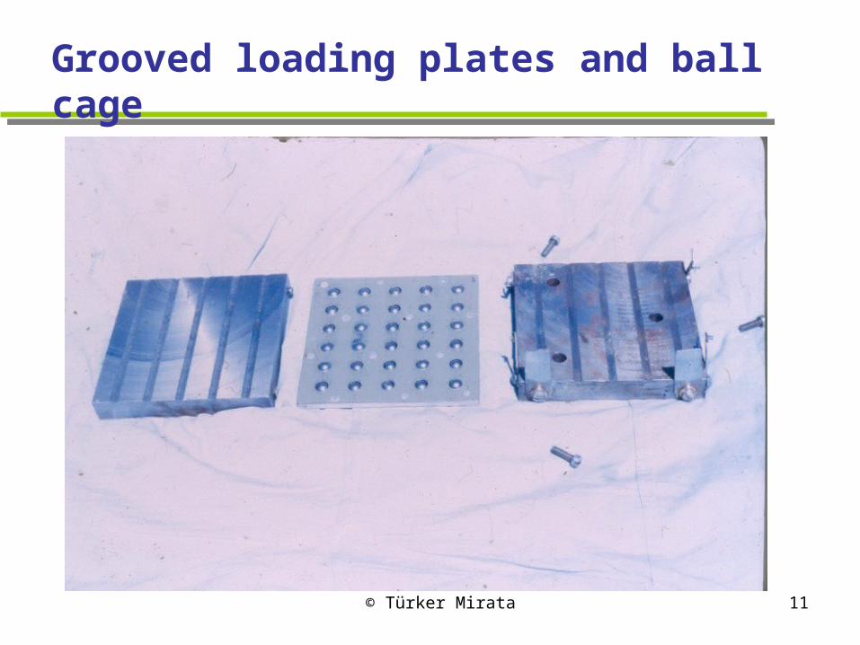
Grooved loading plates and ball cage
© Türker Mirata 12
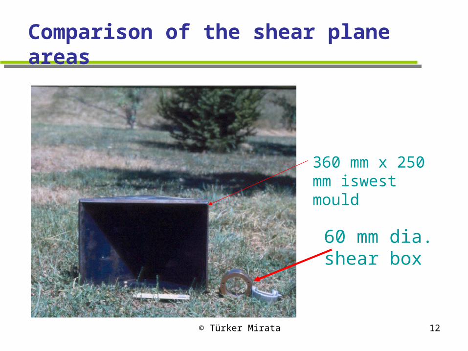
Comparison of the shear plane areas
60 mm dia. shear box
360 mm x 250 mm iswest mould

© Türker Mirata 13
All equipment used for the iswests
© Türker Mirata 14
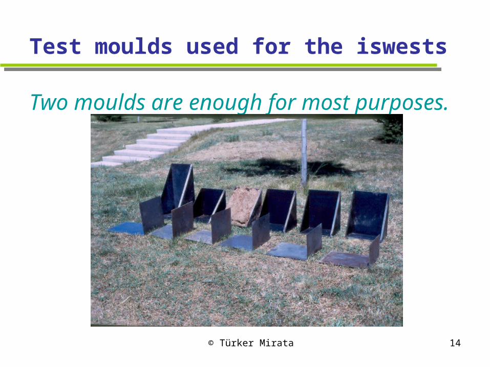
Test moulds used for the iswests
Two moulds are enough for most purposes.
© Türker Mirata 15
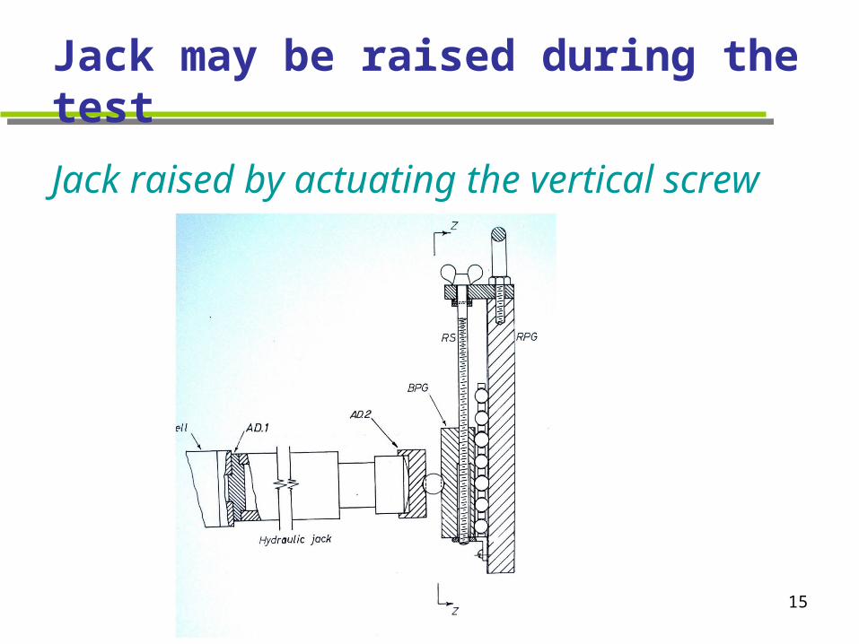
Jack may be raised during the test
Jack raised by actuating the vertical screw

© Türker Mirata 16
Earlier loading setup
Load applied on face of test mould through steel balls and a loading plate

© Türker Mirata 17
Improved loading setup
Load applied through two grooved plates with steel balls in between
© Türker Mirata 18
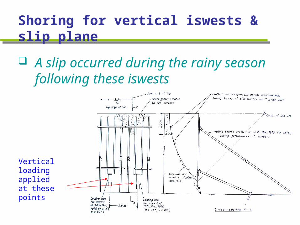
Shoring for vertical iswests & slip plane
A slip occurred during the rainy season following these iswests
Vertical loading applied at these points

© Türker Mirata 19
Vertical loading on side of cut
Iswest with vertical loading

© Türker Mirata 20
The shoring after the slip
This type of shoring proved unsuccessful
This showed it is safer to do such tests at the side of an adequately supported test pit.
© Türker Mirata 21
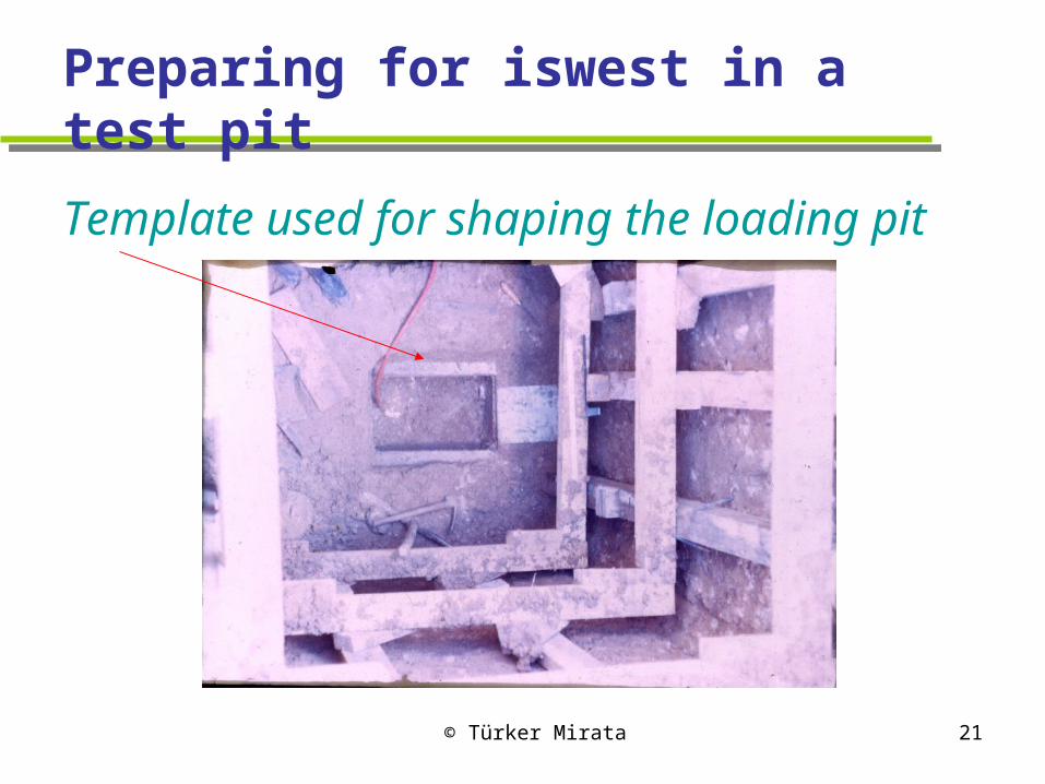
Preparing for iswest in a test pit
Template used for shaping the loading pit

© Türker Mirata 22
Sides of soil wedge being cut
L-shaped lamina used to aid this operation

© Türker Mirata 23
Gauging stool for checking size of loading pit
Note the graduations on the legs for different
test moulds
© Türker Mirata 24
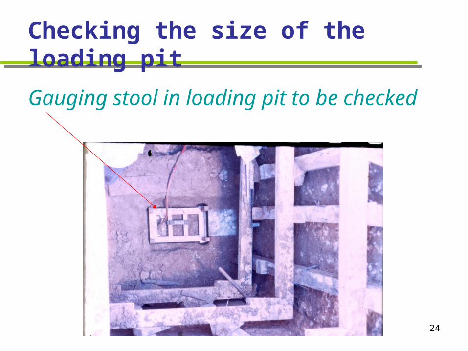
Checking the size of the loading pit
Gauging stool in loading pit to be checked
© Türker Mirata 25
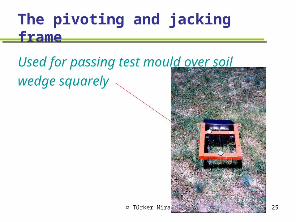
The pivoting and jacking frame
Used for passing test mould over soil
wedge squarely

© Türker Mirata 26
Marks on the cutting edges of test mould
These aid in positioning the test mould

© Türker Mirata 27
Iswest in progress at bottom of pit
June 1971

© Türker Mirata 28
Iswest in pit supported by expansible steel segments
Bent out of 3 mm thick
mild steel plate, eight
such 40 mm high
segments ranging
between 1035 and 1255
mm in dia. were used to
support a 4 m deep pit.

© Türker Mirata 29
Comparison of factors of safety for three slips in the stiff fissured Ankara Clay
1.00 1.20 1.40 1.60
1.80 2.00 2.20 2.40
Slip 1 Slip 2 Slip 3
Fa
cto
r o
f s
afe
ty
Effective stress analysis based on triaxial tests on 36mm dia. specimens
Total stress analysis based on iswestsEffective stress analysis based on triaxial tests on 102mm dia. specimens
© Türker Mirata 30
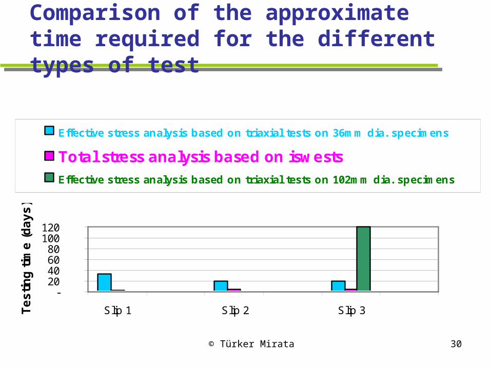
Comparison of the approximate time required for the different types of test
- 20 40 60 80
100 120
Slip 1 Slip 2 Slip 3Te
sti
ng
tim
e (
da
ys
)
Effective stress analysis based on triaxial tests on 36mm dia. specimens
Total stress analysis based on iswests
Effective stress analysis based on triaxial tests on 102mm dia. specimens

© Türker Mirata 31
2. Cylindrical wedge shear test (cylwest)
Suitable for testing clayey tube samples up to about 100 mm in diameter, recovered from boreholes.
Suitlable for compaction control of clay fills.
Can be performed on clays or sands compacted directly in the cylwest mould.

© Türker Mirata 32
Principle of the cylwest
The sample is introduced in a thin-walled steel tubecut at an angle between 30o and 45o to its axis. Upper half of mould is clampedin the cross-beam of an existing compressionmachine or portable frame. Spacers are removed. Loading is effected ina similar way to that in iswests.
© Türker Mirata 33
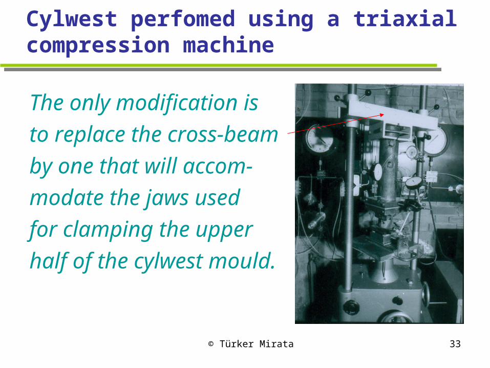
Cylwest perfomed using a triaxial compression machine
The only modification is
to replace the cross-beam
by one that will accom-
modate the jaws used
for clamping the upper
half of the cylwest mould.
© Türker Mirata 34
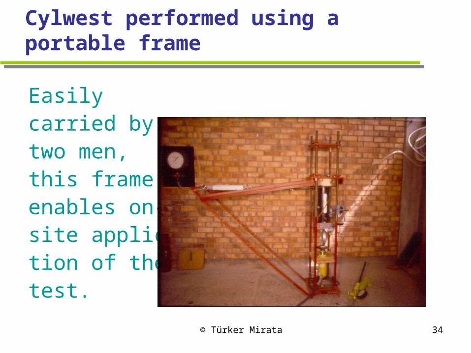
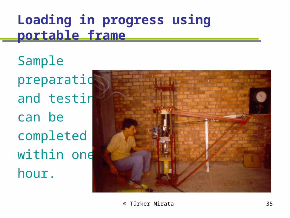
Cylwest performed using a portable frame
Easilycarried bytwo men,this frameenables on-site applica-tion of the test.
© Türker Mirata 35
Loading in progress using portable frame
Sample
preparation
and testing
can be
completed
within one
hour.

© Türker Mirata 36
Double-cut test mould
Used for testing compacted
soils in the same mould in
which they are compacted
One half of removed upper coupling
© Türker Mirata 37
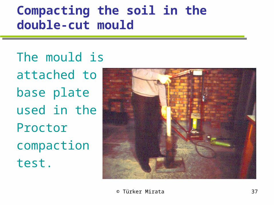
Compacting the soil in the double-cut mould
The mould is
attached to the
base plate
used in the
Proctor
compaction
test.
© Türker Mirata 38
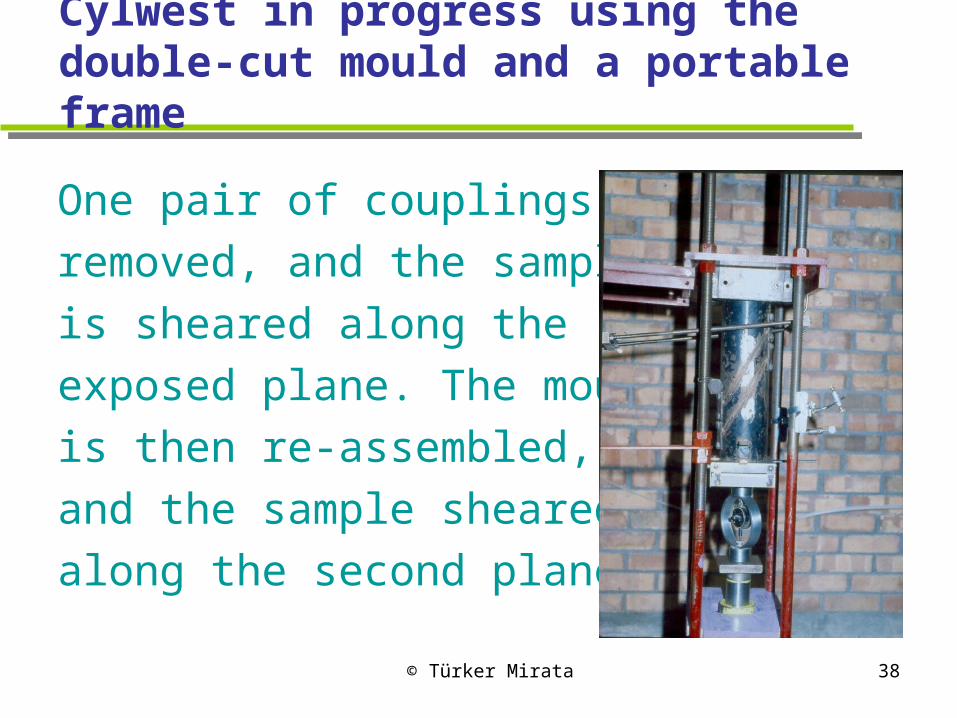
Cylwest in progress using the double-cut mould and a portable frame
One pair of couplings is
removed, and the sample
is sheared along the
exposed plane. The mould
is then re-assembled,
and the sample sheared
along the second plane.

© Türker Mirata 39
Shear strength envelopes from cylwests and shear box tests on clays compared
Segments
of peak
strength
envelopes
© Türker Mirata 40
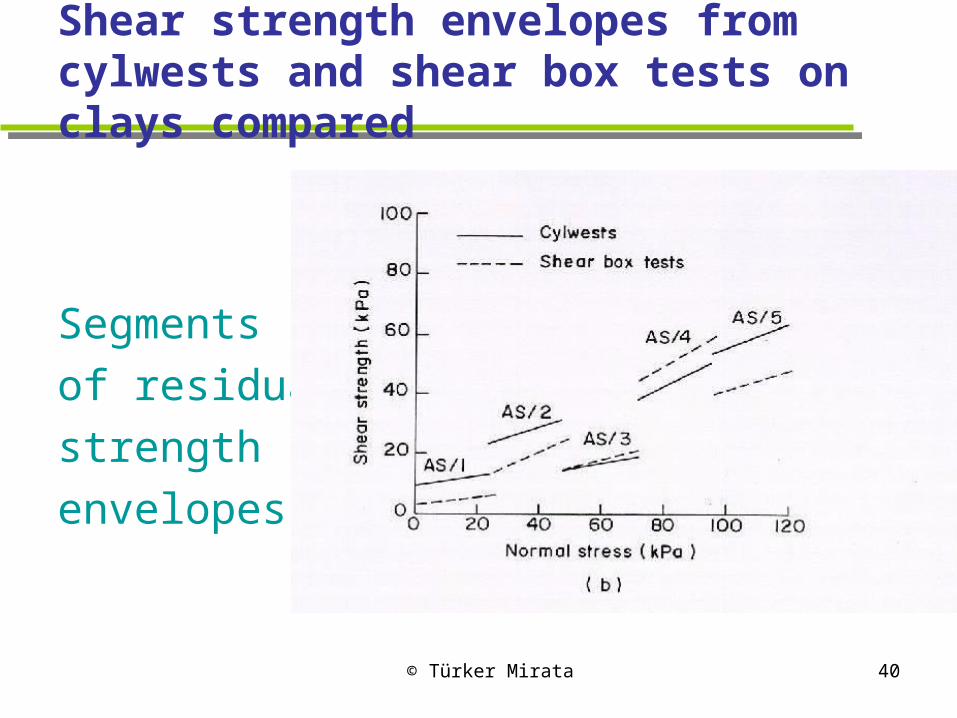
Shear strength envelopes from cylwests and shear box tests on clays compared
Segments
of residual
strength
envelopes
© Türker Mirata 41
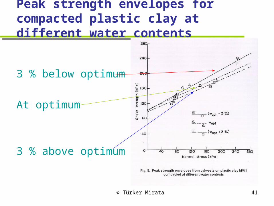
Peak strength envelopes for compacted plastic clay at different water contents
3 % below optimum
At optimum
3 % above optimum

© Türker Mirata 42
Peak strength envelopes for compacted sandy clay at different water contents
3 % below optimum
At optimum
3 % above optimum

© Türker Mirata 43
Peak envelopes for compacted plastic clay at different compactive efforts
25 blows per
Layer
20 blows per
Layer
15 blows per
layer

© Türker Mirata 44
Peak envelopes for compacted sandy clay at different compactive efforts
25 blows per
Layer
20 blows per
Layer
15 blows per
layer
© Türker Mirata 45
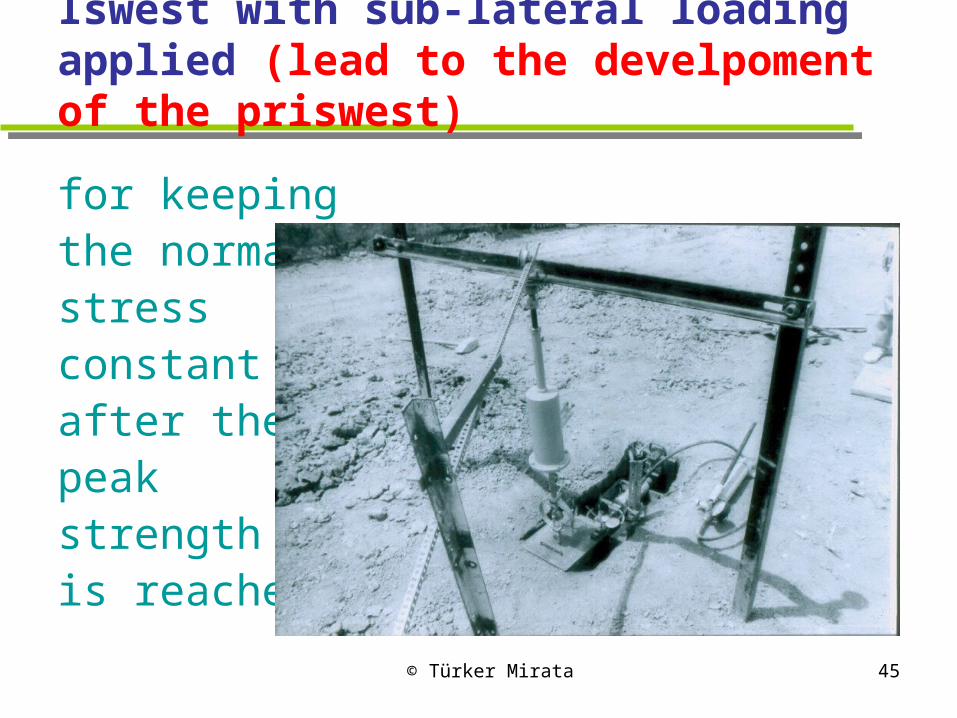
Iswest with sub-lateral loading applied (lead to the develpoment of the priswest)
for keepingthe normalstressconstantafter thepeakstrengthis reached.
© Türker Mirata 46
3. Prismatic wedge shear test (priswest)
Suitable for testing gravel, crushed rock, and clay with < 38 mm particles.
Enables static compaction to be applied for clayey samples.
Can be performed in the lab or on site within two hours.
Total weight of equipment needed is about 250 kg – ¼ of a conventional shear box for the same size of samples.
© Türker Mirata 47
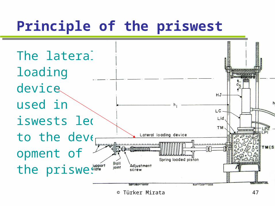
Principle of the priswest
The lateral loading device used in iswests ledto the devel-opment ofthe priswest.
© Türker Mirata 48
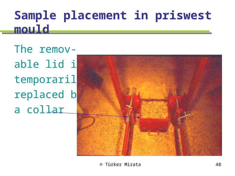
Sample placement in priswest mould
The remov-
able lid is
temporarily
replaced by
a collar
© Türker Mirata 49
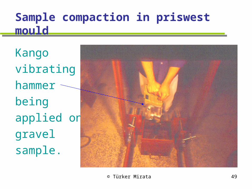
Sample compaction in priswest mould
Kango
vibrating
hammer
being
applied on
gravel
sample.

© Türker Mirata 50
Loading setup used for priswests (1)
The 5-toncapacityportableframe. Verticalloading is used for clay.

© Türker Mirata 51
Loading setup used for priswests (2)
20-ton
capacity
frame.
Horizontal
loading is
used for
gravel.

© Türker Mirata 52
Priswest in progress using 20-ton frame
Dial gauges
are used
to measure
displace-
ments.
© Türker Mirata 53
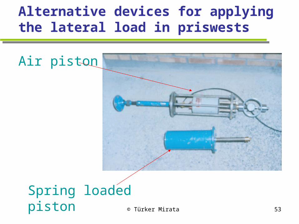
Alternative devices for applying the lateral load in priswests
Air piston
Spring loaded piston
© Türker Mirata 54
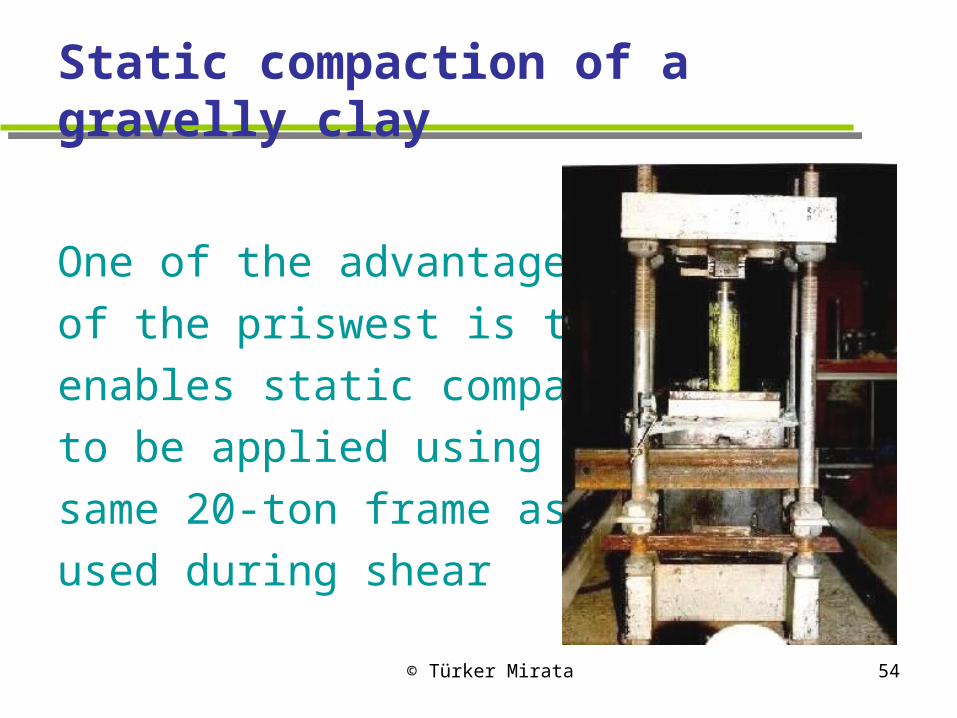
Static compaction of a gravelly clay
One of the advantages
of the priswest is that it
enables static compaction
to be applied using the
same 20-ton frame as
used during shear
© Türker Mirata 55
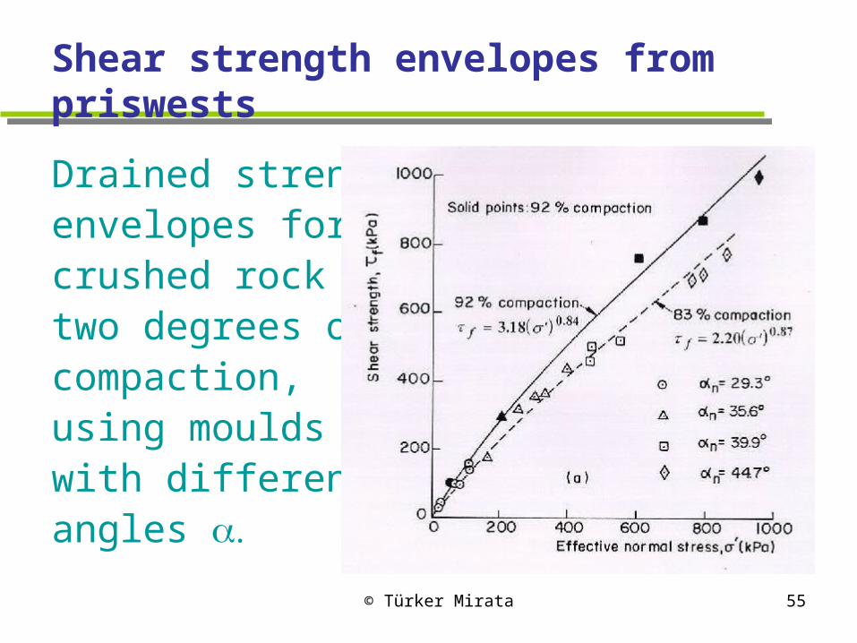
Shear strength envelopes from priswests
Drained strength envelopes for crushed rock at two degrees of compaction, using moulds with differentangles
© Türker Mirata 56
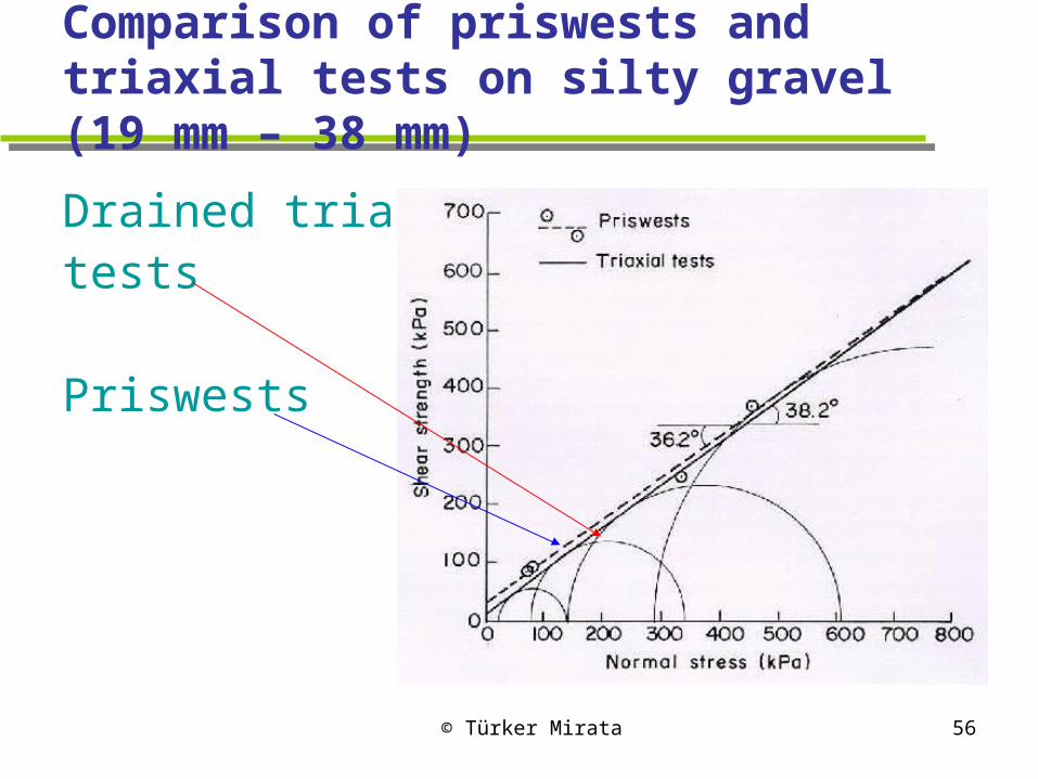
Comparison of priswests and triaxial tests on silty gravel (19 mm – 38 mm)
Drained triaxial tests
Priswests
© Türker Mirata 57
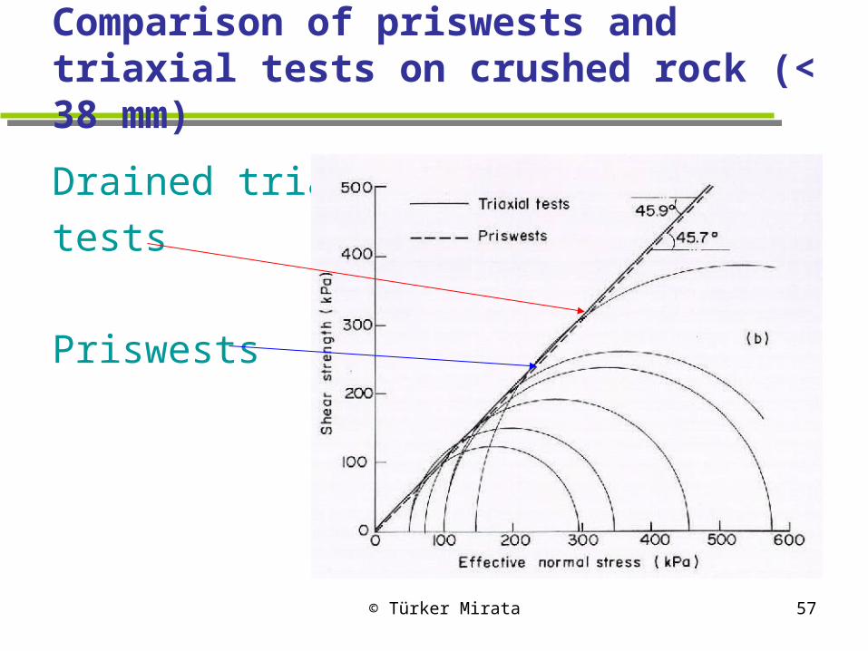
Comparison of priswests and triaxial tests on crushed rock (< 38 mm)
Drained triaxial
tests
Priswests
© Türker Mirata 58
Why should the results be so close?
The priswest, being close to plane strain conditions, would be expected to give a somewhat higher strength than the triaxial test.
Cylwests on sand do give a somewhat higher strength than the triaxial test.
The answer to this apparent anomaly is given in the next slide.

© Türker Mirata 59
Plot of peak friction angles vs. angle between shear plane and bedding planes for six different sands
Cylwestswith abt.same as triaxialtests give higher
(deg)
Priswestshave lowerthan triaxial tests Angle between shear plane and bedding planes, (degrees)

© Türker Mirata 60
Duration of priswests and triaxial tests
- 2 4 6 8
Gravel Crushed rock Gravelly clay(undrained
test)
Test
ing
time (
hour
s)
Triaxial tests on 190 mm samples
Priswests on 300 mm x 300 mm samples
© Türker Mirata 61
Those who have helped investigate the different aspects of the wedge shear test:
Aybak, Turgut (M.Sc, 1988). Köseoğlu, Rüştü (M.Sc, 1988). Azimli, Fuat (M.Sc, 1989). Varan, Mustafa (M.Sc, 1989). Çağnan, Şener (M.Sc, 1990). Seçkin, Altan (M.Sc, 1993). Turp, Engin Zülfükar (M.Sc, 1993).

© Türker Mirata 62
Those who have helped investigate the different aspects of the wedge shear test
(continued) Gökalp, Alp (M.Sc, 1994). Şakar, Mehmet (M.Sc, 1997). Gün, Fırat (M.Sc, 1997). Filiz, T. Emrin (M.Sc, 2000). Erzin, Yusuf (PhD, 2004).
© Türker Mirata 63
Special thanks are due to
The many METU technicians who have made the special equipment.
The METU technicians who have helped during the testing.
All colleagues who have helped in different ways.
Last but not least, Dr. Murat Mirata for help in preparing this PowerPoint show.
© Türker Mirata 64
THE END
Thanks for watching. For details see literature listed at http://www.metu.edu.tr/~mirata/
16 March 2007


