Wednesday, May 4, 2016 Development Review Committee DEVELOPMENT REVIEW COMMITTEE AGENDA PUBLIC NOTICE is hereby given that the Development Review Committee of Spanish Fork, Utah, will hold a regular meeting in the Council Chambers in the City O䌼ce Building, 40 South Main Street, Spanish Fork, Utah, commencing at 10:00 a.m. 1. Policy Changes File Attachments _Construction Standards Revision Feb 2016 Combined Updates (03) 4-21-201....pdf (2,293 KB) Draft POLICY 39 - Construction Standards Revision Changes Only (07) 4-22....pdf (311 KB) Growth related infrastructure that does not have local connection shall be eligible for 100% reimbursement through impact fees. If there will be local connections then the difference between the regional and local infrastructure cost may be reimbursed. 2. Adjourn Subject A. City Standards Policy 39 Meeting May 4, 2016 - Development Review Committee Category 1. Policy Changes Access Public Type Action, Discussion Subject B. 4.30.010 - Impact Fee Reimbursable Projects Meeting May 4, 2016 - Development Review Committee Category 1. Policy Changes Access Public Type Action, Discussion
Transcript
Wednesday, May 4, 2016Development Review Committee
DEVELOPMENT REVIEW COMMITTEE AGENDA PUBLIC NOTICE is hereby given that the Development Review Committee of Spanish Fork, Utah, will hold aregular meeting in the Council Chambers in the City O䌼�ce Building, 40 South Main Street, Spanish Fork,Utah, commencing at 10:00 a.m.
1. Policy Changes
File Attachments_Construction Standards Revision Feb 2016 Combined Updates (03) 4-21-201....pdf (2,293 KB)Draft POLICY 39 - Construction Standards Revision Changes Only (07) 4-22....pdf (311 KB)
Growth related infrastructure that does not have local connection shall be eligible for 100% reimbursement through impactfees. If there will be local connections then the difference between the regional and local infrastructure cost may bereimbursed.
2. Adjourn
Subject A. City Standards Policy 39
Meeting May 4, 2016 - Development Review Committee
Category 1. Policy Changes
Access Public
Type Action, Discussion
Subject B. 4.30.010 - Impact Fee Reimbursable Projects
Meeting May 4, 2016 - Development Review Committee
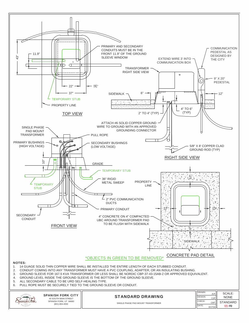
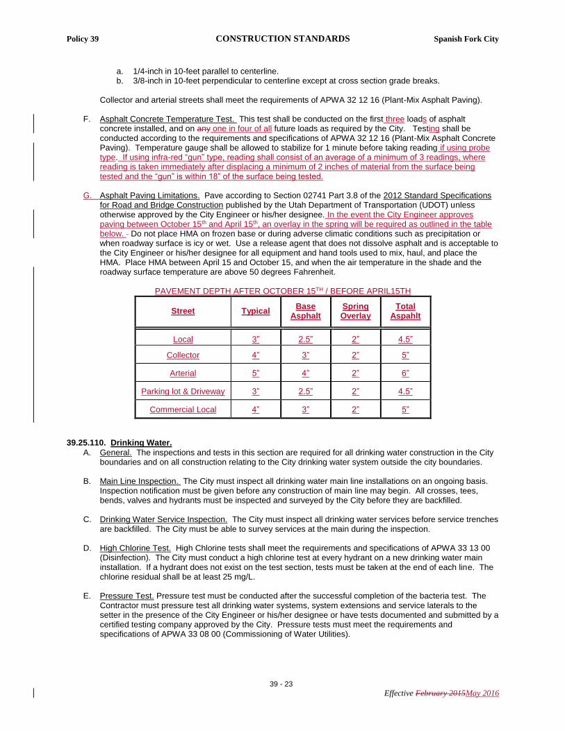
STEEL REINFORCEDPLASTIC MANHOLE STEPS@ 12" O.C. IN LINE AND ONSAME SIDE AS OPENING
A D&L 1180 OR EQUIVALENT MANHOLEFRAME AND LID RECESSED 1/4" BELOW
FINISHED GRADE. LID MUST BELABELED "WATER" WITH 1 7/8" HOLE
FINISH GRADE(1' HIGHER
THAN EXISTINGGRADE)
2'x2'x2'PRECAST BOX
3/4" WASHEDDRAIN ROCK
NOTES:1. RESTRAIN ALL JOINTS.2. SLOPE FLOOR TO DRAIN3. CLA-WALS TO HAVE SS TRIM
EYE BOLT(SEE DETAIL)
SEE DETAIL "B"
SEE DETAIL "A"
SPANISH FORK CITY40 SOUTH MAIN STREET
SPANISH FORK, UT 84660(801) 804-4550
DRAWN:
DESIGN:
CHECK:
DATE:
JLR
CJP
CMT
11/9/15
STANDARD DRAWINGSCALE:NONE
STANDARD__
PRV DETAIL
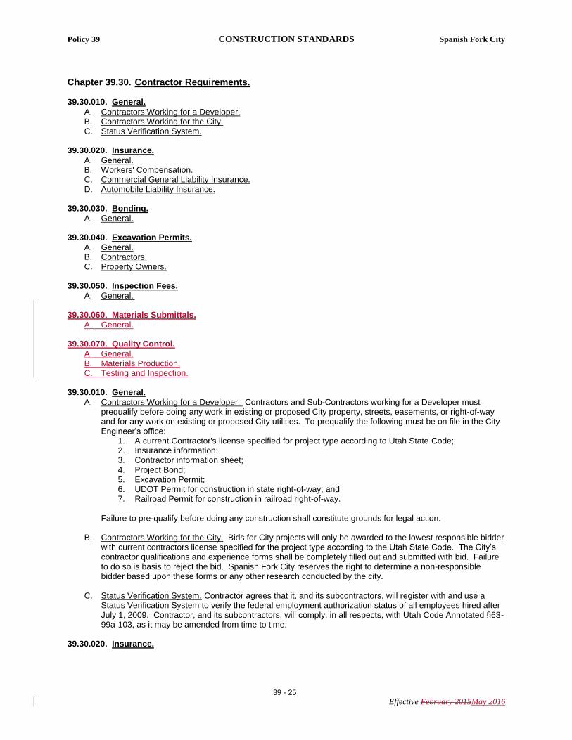
FULL HEIGHTCURB
RADIUS PLATE (TYP.)
5'RAMP
2'
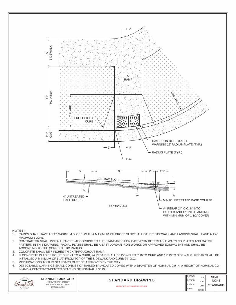
NOTES:1. RAMPS SHALL HAVE A 1:12 MAXIMUM SLOPE, WITH A MAXIMUM 2% CROSS SLOPE. ALL OTHER SIDEWALK AND LANDING SHALL HAVE A 1:48
MAXIMUM SLOPE.2. CONTRACTOR SHALL INSTALL PAVERS ACCORDING TO THE STANDARDS FOR CAST-IRON DETECTABLE WARNING PLATES AND MATCH
PATTERN IN THIS DRAWING. RADIAL PLATES SHALL BE A EAST JORDAN IRON WORKS OR APPROVED EQUIVALENT AND SHALL BEACCORDING TO THE CORRECT TBC RADIUS.
3. CONCRETE SHALL BE 7 INCHES THICK THROUGHOUT RAMP.4. IF CONCRETE IS TO BE POURED NEXT TO A CURB, #4 REBAR SHALL BE DOWELED 6" INTO CURB AND 12" INTO SIDEWALK. REBAR SHALL BE
INSTALLED A MINIMUM OF 1 1/2" FROM TOP OF THE SIDEWALK AND CURB 24" O.C.5. MODIFICATIONS TO THIS STANDARD MUST BE APPROVED BY THE CITY.6. DETECTABLE WARNINGS SHALL CONSIST OF RAISED TRUNCATED DOMES WITH A DIAMETER OF NOMINAL 0.9 IN, A HEIGHT OF NOMINAL 0.2
IN AND A CENTER-TO-CENTER SPACING OF NOMINAL 2.35 IN.
#4 REBAR 24" O.C. 6" INTOGUTTER AND 12" INTO LANDINGWITH MINIMUM OF 1 1/2" COVER
MIN 8" UNTREATED BASE COURSE
1/2" 0" 2"
R25' (TBC)
6' F
LAR
E
A
A
SPANISH FORK CITY40 SOUTH MAIN STREET
SPANISH FORK, UT 84660(801) 804-4550
DRAWN:
DESIGN:
CHECK:
DATE:
JLR
CJP
CMT
4/20/16
STANDARD DRAWINGSCALE:NONE
STANDARD__
REDUCED WIDTH RAMP DESIGN
SPANISH FORK CITY40 SOUTH MAIN STREET
SPANISH FORK, UT 84660(801) 804-4550
DRAWN:
DESIGN:
CHECK:
DATE:
JLR
CJP
CMT
4/20/16
STANDARD DRAWINGSCALE:NONE
STANDARD__
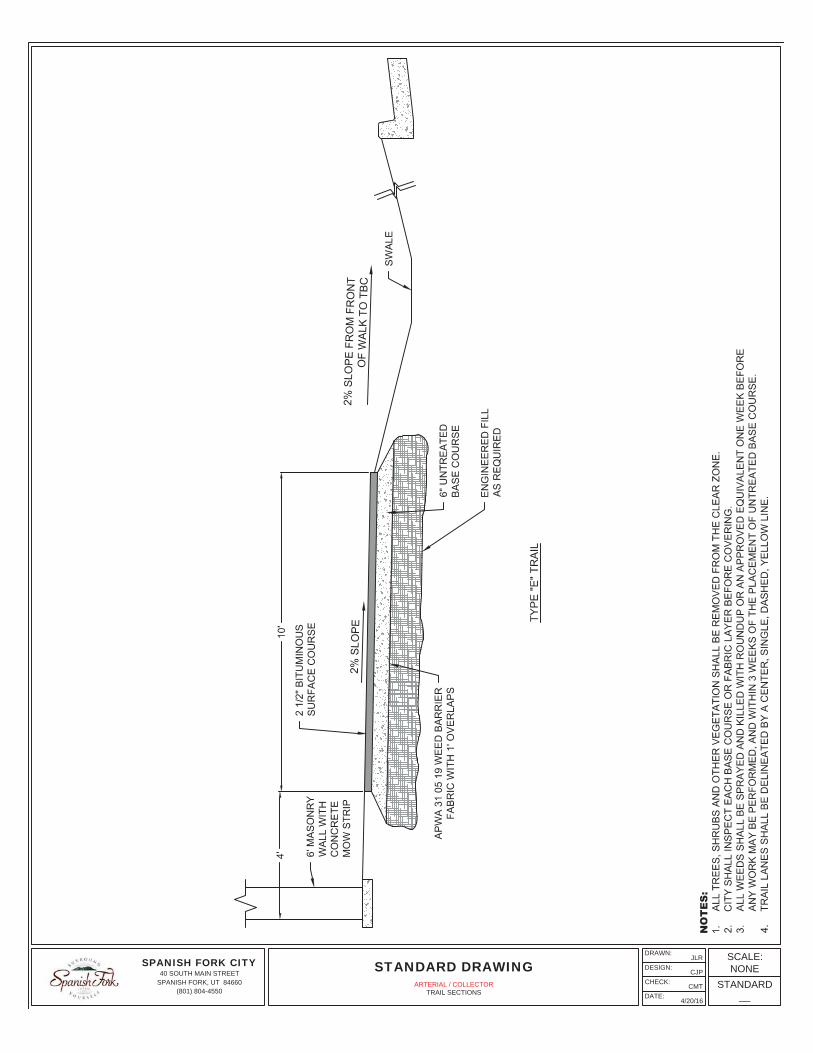
ARTERIAL / COLLECTORTRAIL SECTIONS
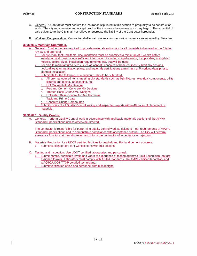
48" P
RE
CA
ST
CO
NC
RE
TE M
AN
HO
LE L
ID
SID
EW
ALK
NO
TE
S:
1.B
UR
Y C
ON
DU
IT 1
8" B
ELO
W G
RA
DE
.2.
CO
NTR
AC
TOR
SH
ALL
INS
TALL
1 1
/2" A
ND
2" M
ETE
RS
(ME
TER
TO
BE
PR
OV
IDE
D B
Y S
PA
NIS
H F
OR
K C
ITY
).3.
TYP
E O
F M
ETE
R T
O B
E U
SE
D S
HA
LL B
E D
ETE
RM
INE
D B
Y T
HE
CIT
Y.
21" M
ETE
R S
ETT
ER
WIT
HD
UA
L C
HE
CK
VA
LVE
IRO
N P
IPE
BY
CO
MP
RE
SS
ION
BA
LL T
YP
E C
OR
P S
TOP
202B
DO
UB
LE B
RA
SS
STR
AP
FO
RD
SA
DD
LE O
R A
PP
RO
VE
DE
QU
IVA
LEN
T O
NTO
WA
TER
MA
IN
GR
AD
EC
UR
B &
GU
TTE
R
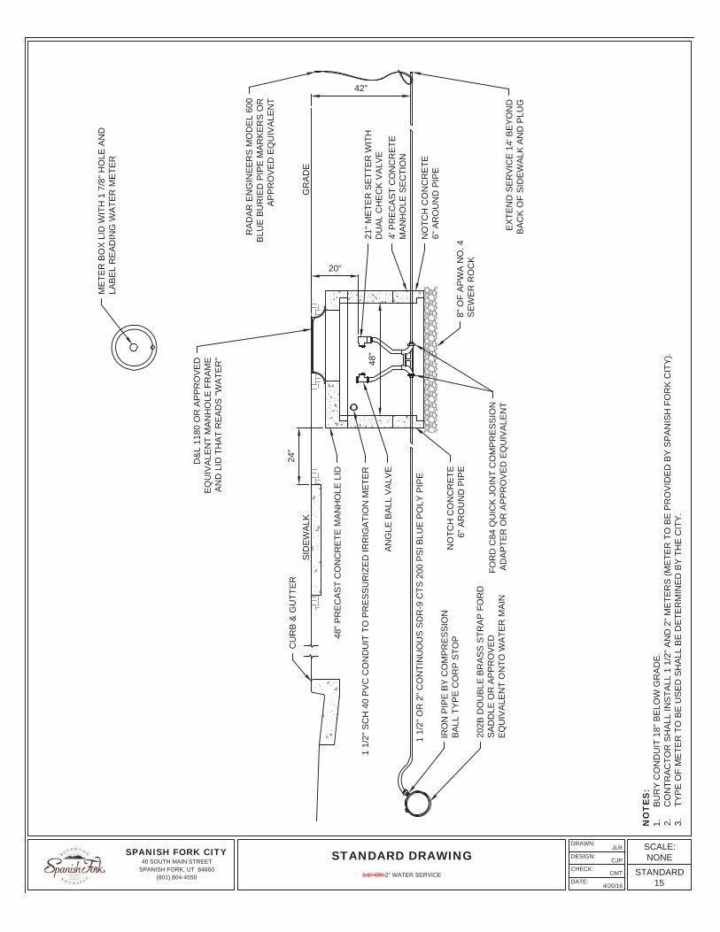
42"
D&
L 11
80 O
R A
PP
RO
VE
DE
QU
IVA
LEN
T M
AN
HO
LE F
RA
ME
AN
D L
ID T
HA
T R
EA
DS
"WA
TER
"
24"
RA
DA
R E
NG
INE
ER
S M
OD
EL
600
BLU
E B
UR
IED
PIP
E M
AR
KE
RS
OR
AP
PR
OV
ED
EQ
UIV
ALE
NT
ME
TER
BO
X L
ID W
ITH
1 7
/8" H
OLE
AN
DLA
BE
L R
EA
DIN
G W
ATE
R M
ETE
R
EX
TEN
D S
ER
VIC
E 1
4' B
EY
ON
DB
AC
K O
F S
IDE
WA
LK A
ND
PLU
G
NO
TCH
CO
NC
RE
TE6"
AR
OU
ND
PIP
E
8" O
F A
PW
A N
O. 4
SE
WE
R R
OC
K
FOR
D C
84 Q
UIC
K J
OIN
T C
OM
PR
ES
SIO
NA
DA
PTE
R O
R A
PP
RO
VE
D E
QU
IVA
LEN
T
NO
TCH
CO
NC
RE
TE6"
AR
OU
ND
PIP
E
AN
GLE
BA
LL V
ALV
E
1 1/
2" S
CH
40
PV
C C
ON
DU
IT T
O P
RE
SS
UR
IZE
D IR
RIG
ATI
ON
ME
TER
4' P
RE
CA
ST
CO
NC
RE
TEM
AN
HO
LE S
EC
TIO
N
20"
1 1/
2" O
R 2
" CO
NTI
NU
OU
S S
DR
-9 C
TS 2
00 P
SI B
LUE
PO
LY P
IPE
48"
SPANISH FORK CITY40 SOUTH MAIN STREET
SPANISH FORK, UT 84660(801) 804-4550
DRAWN:
DESIGN:
CHECK:
DATE:
JLR
CJP
CMT
4/20/16
STANDARD DRAWINGSCALE:NONE
STANDARD15
1.5'' OR 2'' WATER SERVICE
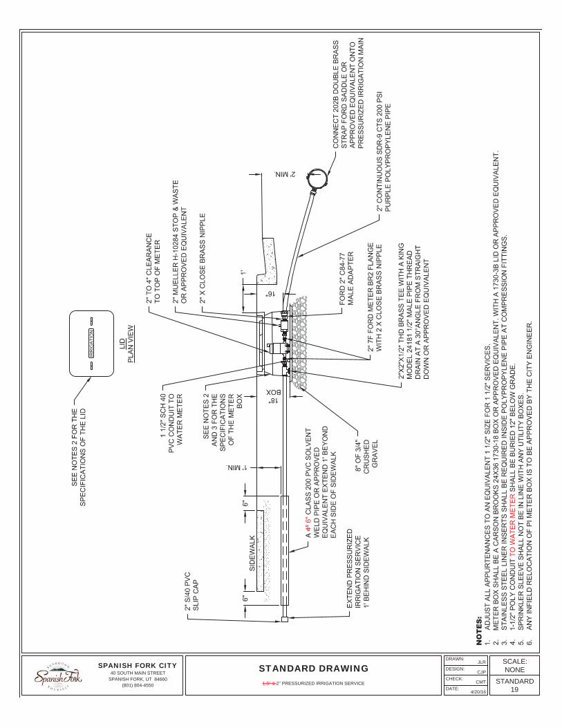
NOTES:1. STANDARD SERVICE SIZE SHALL BE 1" CONTINUOUS SDR-9 CTS 200 PSI PURPLE POLYPROPYLENE PIPE.2. STAINLESS STEEL LINER INSERTS WILL BE REQUIRED INSIDE OF TUBING AT COMPRESSION FITTINGS.3. ALL FITTINGS SHALL BE COMPATIBLE WITH SERVICE SIZE.4. SERVICE LATERAL SHALL SLOPE TOWARDS PRESSURIZED IRRIGATION MAIN.5. SPRINKLER SLEEVE SHALL NOT BE IN LINE WITH ANY UTILITY BOXES.6. 1-1/2" POLY CONDUIT SHALL BE BURIED 12" BELOW GRADE.7. FOR TRAFFIC AREAS, USE A CDR SYSTEMS CORP 16X21X18 FIBERGLASS REINFORCED POLYMER CONCRETE BOX WITH "IRRIGATION" MARKED
ON THE LID.
GRADE
CARSON-BROOKS 1220-12IRRIGATION BOX WITH CARSON
BROOKS 1220-4 BOLT-DOWN COVER,OR APPROVED EQUIVALENT, WITH
ONE 1220-6X EXTENSIONS.
1'
METER SHALL BEPROVIDED BY THE CITYAND INSTALLED BY THECONTRACTOR
1-1/2" SCH 40 PVC CONDUITTO WATER METER
MUELLER 1" H-10284 STOP AND WASTEOR APPROVED EQUIVALENT
1" X CLOSE BRASS NIPPLE
FORD 1" C84-44 MALE ADAPTER ORAPPROVED EQUIVALENT
6" OF APWA NO. 4SEWER ROCK
1" SCH40 PVCMALE ADAPTER
PLUG 12" OUTOF METER BOX
1" SCH 40 PVC
1"X1"X1/2" THD BRASS TEE WITH A KING MODEL 241811/2" MALE PIPE THREAD DRAIN AT A 30° ANGLE FROM
STRAIGHT DOWN OR APPROVED EQUIVALENT
FORD C38-24-2.5 B 1" X 2 1/2" STRAIGHTMETER COUPLING BY MALE IRON PIPETHREAD OR APPROVED EQUIVALENT
A 4" CLASS 200 PVC SOLVENTWELD PIPE OR APPROVEDEQUIVALENT EXTEND 1' BEYONDEACH SIDE OF SIDEWALK
CONNECT 202B BRASS DOUBLE STRAP FORDSADDLE OR APPROVED EQUIVALENT ONTO
PRESSURIZED IRRIGATION MAIN
LIDPLAN VIEW
IRRIGATION
SPANISH FORK CITY40 SOUTH MAIN STREET
SPANISH FORK, UT 84660(801) 804-4550
DRAWN:
DESIGN:
CHECK:
DATE:
JLR
CJP
CMT
4/21/16
STANDARD DRAWINGSCALE:NONE
STANDARD18
1'' PRESSURIZED IRRIGATION SERVICE BOX AND LATERAL
SPANISH FORK CITY40 SOUTH MAIN STREET
SPANISH FORK, UT 84660(801) 804-4550
DRAWN:
DESIGN:
CHECK:
DATE:
JLR
CJP
CMT
4/20/16
STANDARD DRAWINGSCALE:NONE
STANDARD19
1.5'' & 2'' PRESSURIZED IRRIGATION SERVICE
A A
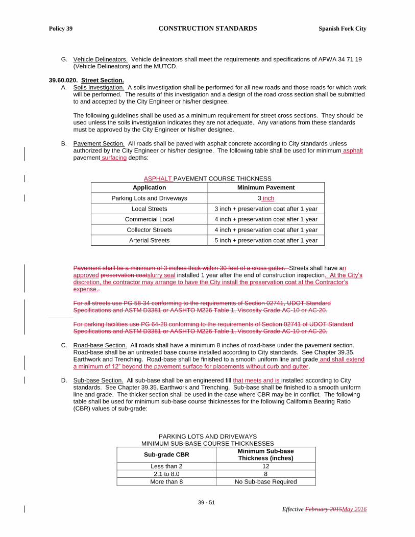
PRECAST CONCRETEBASE SECTION
6" COMPACTED UNTREATEDBASE COURSE
A D&L 1180 OR EQUIVALENT MANHOLEFRAME AND LID RECESSED 1/4" BELOWFINISHED GRADE WHICH READS "SEWER","STORM DRAIN", "WATER", OR "IRRIGATION"AS APPROPRIATE (SEE NOTE 9)
MINIMUM OF ONE 4" OR 6" PRECASTCONCRETE GRADE RING REQUIRED(TWO GRADE RINGS MAXIMUM)
PRECAST CONCRETEECCENTRIC CONE SECTION
ALL WEATHER BUTYL SEALANT INROPE FORM AT ALL JOINTS, SEAL ALLLIFT HOLES WITH NON-SHRINK GROUT
PSX DIRECT BOOT ORAPPROVED EQUIVALENT
FORSHEDA PIPE LEAD-IN ORAPPROVED EQUAL
4' TO 6'
2'-3"
4'-6"
3'
SEWER
NOTES:1. USE 4' I.D. MANHOLES FOR MAIN LINES LESS THEN 18" IN DIAMETER; 5' I.D. MANHOLES FOR MAIN LINES 18" TO 30" IN DIAMETER, AND 6' I.D. FOR
MAIN LINES GREATER THAN 30" IN DIAMETER.2. FLAT LIDS MAY BE USED IN LIEU OF ECCENTRIC CONES WHERE NECESSARY. FLAT LIDS SHALL BE OF ECCENTRIC DESIGN AND MEET H20 LIVE
LOADING. NO FLAT RING AND COVERS WILL BE ALLOWED UNLESS APPROVED BY CITY ENGINEER OR HIS/HER DESIGNEE.3. MANHOLE RIMS PLACED IN FIELDS SHALL HAVE SOLID LIDS AND BE BURIED 2 FEET DEEP.4. MANHOLE RIMS OUT OF STREETS SHALL BE PLACED 4 INCHES ABOVE GRADE.5. CONCRETE COLLAR AND RIM SHALL BE INSTALLED 1/4" BELOW PAVEMENT SURFACE AFTER THE 1 YEAR PRESERVATION COAT.6. MANHOLE COLLARS AND RINGS SHALL BE PROTECTED BY A COVERING DURING A SEAL COAT.7. STORM MANHOLES MAY HAVE FLAT BOTTOMS IN THE BASES.8. CONCRETE COLLAR SHALL BE PLACED AFTER THE 1 YEAR PRESERVATION COAT WHEN APPLICABLE.9. IN PAVED AREAS WITH A SLOPE GREATER THAN 5% USE AN EJIW 3624 TWIST BASE OR APPROVED EQUIVALENT.10. ALL STORM DRAIN MANHOLES CONNECTED TO STORM DRAIN INLETS SHALL HAVE A FLAT BOTTOM WITH 18" MIN. FROM FLOW LINE TO BOTTOM
OF BOX.11. ALL STORM DRAIN MANHOLES NOT CONNECTED TO AN INLET BOX SHALL HAVE A TROUGH.
1" R ON CORNERS OFCONCRETE COLLAR
FINISH GRADE
12" COMPACTEDUNTREATED BASE COARSE
PRECAST CONC. SECTIONFURNISHED IN 12", 24", 36" AND
48" HEIGHTS AS REQUIRED
5" FOR 48" I.D.6" FOR 60" I.D.7" FOR 72" I.D.
8" CONCRETE MANHOLE COLLAR
2'-6"
8" GROUT OVER ANY LIP ONTHE INSIDE OF MANHOLE
CONCRETE COLLAR WITH FIBER MESHREINFORCEMENT APWA 03 20 00(CONCRETE REINFORCING)
SPANISH FORK CITY40 SOUTH MAIN STREET
SPANISH FORK, UT 84660(801) 804-4550
DRAWN:
DESIGN:
CHECK:
DATE:
JLR
CJP
CMT
4/20/16
STANDARD DRAWINGSCALE:NONE
STANDARD21
MANHOLE
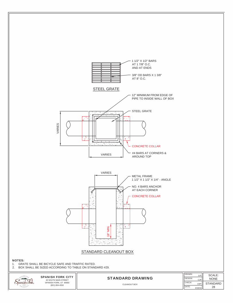
NOTES:1. ALL STORM TRANSMISSION LINES SHALL RUN THROUGH STORM MANHOLES.2. BOX SHALL BE SIZED ACCORDING TO TABLE ON STANDARD #32.3. UNLESS OTHERWISE DESIGNED BY A LICENSED PROFESSIONAL ENGINEER, #4 REBAR WILL BE SPACED AT MINIMUM OF
12" O.C. IN ALL DIRECTIONS IN CONCRETE, ALL REBAR SHALL OVERLAP A MINIMUM OF 14".
5'-9
" MIN
.
4'-0"
MAY USE A 3 x 3 x 4 PRECAST BOXWHICH MEETS H-2O LOADING ANDASTM SPECIFICATION C-858 FORUNDERGROUND UTILITY STRUCTURES
MINIMUM 4" CLEARANCETO TOP OF PIPE
GROUT ALL AROUND PIPE ANDOVER ANY LIP INTO MANHOLE
TWO LAYERS OF ADS GEOSYNTHETICS 315WTKWOVEN GEOTEXTILE BETWEEN FOUNDATION
STONE AND CHAMBERS 5' MIN WIDECONTINUOUS FABRIC WITHOUT SEAMS
1'
15"
SEE ELECTRIC AND COMMUNICATIONCONDUIT JOINT TRENCH DETAIL
GAS
MASONRY WALL
B
BCURB INLETPLAN VIEW
PAVEMENT
GUTTER
CURBSWALE
STORMTECHSC-740 CHAMBERS
OR APPROVEDEQUIVALENT
SEE LID RESIDENTIALSTREET INLET BOX
EXTEND 12" PIPE TOSTORMTECH WITH A 0.5%
MINIMUM SLOPE
STORM-TECHSC-740 END CAP SOD
PAVEMENT2'-6"
4'-6"
C&G
4:1SLOPE
SECTION B-BCURB INLET
4'-6"SOD
4:1SLOPE
3x3BOXSIDEWALK
VARIES
NATIVE SOIL
3x3 PRECASTCONCRETE BOX
SODSEE INLET BOXSTANDARD
EXTEND 8" PIPE TOBOX WITH A 1%MINIMUM SLOPE
12" PIPE TOSTORM TECH
STORMTECH SC-740CHAMBERS ORAPPROVED EQUIVALENT
B
B
HP
A
A
PLAN VIEW
30'
50' 50'
100'
10'
30'
CURB INLET TO BELOCATED PER DESIGN
SPANISH FORK CITY40 SOUTH MAIN STREET
SPANISH FORK, UT 84660(801) 804-4550
DRAWN:
DESIGN:
CHECK:
DATE:
JLR
CJP
CMT
4/21/16
STANDARD DRAWINGSCALE:NONE
STANDARD31
LOW IMPACT DEVELOPMENT (LID) COLLECTOR / ARTERIAL / COMMERCIAL STREET GRASS SWALE INLET
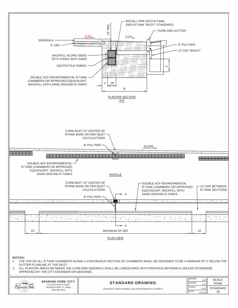
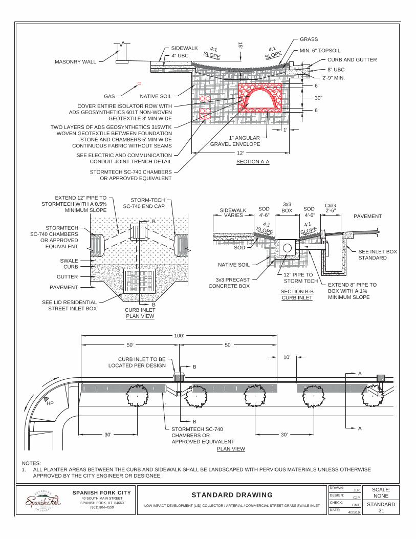
NOTES:1. STREET TREES TO BE MINIMUM OF 3 FEET FROM TBC, SIDEWALK OR TRAIL.2. 2" CALIPER MINIMUM STREET TREES TO BE PLANTED 30 FOOT ON CENTER.3. TREE SPECIES TO BE SPECIFIED BY CONTRACTOR/DESIGNER AND APPROVED BY THE CITY.4. ALL PLANTER AREAS BETWEEN THE CURB AND SIDEWALK SHALL BE LANDSCAPED WITH PERVIOUS MATERIALS UNLESS OTHERWISE
APPROVED BY THE CITY ENGINEER OR DESIGNEE.
5' FROM TBC
TREE PLANTING SECTIONA-A
SEE NOTE 2
4:1SLOPE4:1
SLOPESIDEWALK
4" UBC
NATIVE SOIL
REFER TOCOLLECTOR/ARTERIALLID SWALE
CURB AND GUTTER
8" UBC
12'1.0'
SEE ELECTRIC ANDCOMMUNICATION CONDUIT
JOINT TRENCH DETAIL
GAS
MASONRY WALL
6" 18" M
IN.
SLOPE
A
A
PLAN VIEW
STORMTECH SC-740 CHAMBERSOR APPROVED EQUIVALENT
30'
CURB INLET TO BELOCATED PER DESIGN
50.0' SEE TABLE
10.0'
PROFILE
STORMTECH SC-740 CHAMBERSOR APPROVED EQUIVALENT
CURB INLET TO BELOCATED PER DESIGN TBC
FL
30.0'
EXTEND 12" PIPE TO STORMTECHWITH A 0.5% MINIMUM SLOPE
TABLE 10.35% TO 0.50% 300'0.5% TO 0.75% 200'
>0.75% 100'
SPANISH FORK CITY40 SOUTH MAIN STREET
SPANISH FORK, UT 84660(801) 804-4550
DRAWN:
DESIGN:
CHECK:
DATE:
JLR
CJP
CMT
4/21/16
STANDARD DRAWINGSCALE:NONE
STANDARD33
LOW IMPACT DEVELOPMENT (LID) COLLECTOR / ARTERIAL / COMMERCIAL STREET TREE PLANTING
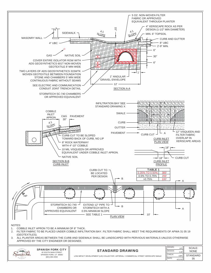
NOTES:1. COBBLE INLET APRON TO BE A MINIMUM OF 8" THICK.2. FILTER FABRIC TO BE PLACED UNDER COBBLE INFILTRATION BAY. FILTER FABRIC SHALL MEET THE REQUIREMENTS OF APWA 31 05 19
(GEOTEXTILES).3. ALL PLANTER AREAS BETWEEN THE CURB AND SIDEWALK SHALL BE LANDSCAPED WITH PERVIOUS MATERIALS UNLESS OTHERWISE
APPROVED BY THE CITY ENGINEER OR DESIGNEE.
TABLE 10.35% TO 0.50% 300'0.5% TO 0.75% 200'
>0.75% 100'
SEE TABLE 1 10'
B
B
A
A
PLAN VIEW
STORMTECH SC-740CHAMBERS OR
APPROVED EQUIVALENT
CURB CUT TOBE LOCATEDPER DESIGN
HP
EXTEND 12" PIPE TOSTORMTECH WITH A
0.5% MINIMUM SLOPE
15"
4:1SLOPE
4:1SLOPE
8" UBCCURB AND GUTTER
MIN. 6" TOPSOIL
4" UBC
SIDEWALK
4" XERISCAPE ROCK AS PERDESIGN (1-1/2" MIN DIAMETER)
5 OZ. NON-WOVEN FILTERFABRIC OR APPROVEDEQUIVALENT THROUGH PLANTER
TWO LAYERS OF ADS GEOSYNTHETICS 315WTKWOVEN GEOTEXTILE BETWEEN FOUNDATION
STONE AND CHAMBERS 5' MIN WIDECONTINUOUS FABRIC WITHOUT SEAMS
1'
SEE ELECTRIC AND COMMUNICATIONCONDUIT JOINT TRENCH DETAIL
GAS
MASONRY WALL
4'-6"
18"
VA
RIE
S
30"-
18"
A
A
COBBLEINLETAPRON C&G PAVEMENT
4:1SLOPE
NATIVE SOIL
8" ROCK WATERWAYWITH 4"-10" COBBLE10 MIL VISQUEEN OR APPROVEDEQUIVALENT UNDER COBBLE INLET APRON.
CURB CUT TO BE SLOPEDTOWARD BACK OF CURB, NO LIP
CURB CUT
PAVEMENT
GUTTER
CURB
SWALE
INFILTRATION BAY SEESTANDARD DRAWING X
CURB CUT12" VISQUEEN ANDFILTER FABRICOVERLAP INXERISCAPE AREAS
CURB INLETPLAN VIEW
CURB INLETPROFILE
SECTION B-BCURB INLET
SPANISH FORK CITY40 SOUTH MAIN STREET
SPANISH FORK, UT 84660(801) 804-4550
DRAWN:
DESIGN:
CHECK:
DATE:
JLR
CJP
CMT
4/21/16
STANDARD DRAWINGSCALE:NONE
STANDARD35
LOW IMPACT DEVELOPMENT (LID) COLLECTOR / ARTERIAL / COMMERCIAL STREET XERISCAPE SWALE
RE
SID
EN
TIA
L LO
CA
L S
TRE
ET
- 60'
RO
W
2%2%
2%5'
8'2.
5'29
'2.
5'8'
5'
13'
34'
13'
60'
SID
EW
ALK
LAN
ES
IDE
WA
LK
℄
NO
TE
S:
1.S
EE
STA
ND
AR
D D
RA
WIN
GS
FO
R S
IDE
WA
LKS
.2.
SU
B-B
AS
E A
S S
PE
CIF
IED
IN T
HE
CO
NS
TRU
CTI
ON
STA
ND
AR
DS
AN
D S
OIL
S R
EP
OR
T.3.
MIN
IMU
M O
F 8"
UN
TRE
ATE
D B
AS
E C
OU
RS
E U
ND
ER
STR
EE
T P
AV
EM
EN
T A
ND
CU
RB
& G
UTT
ER
UN
LES
S M
OR
E R
EQ
UIR
ED
BY
SO
ILS
RE
PO
RT
4.A
LL L
OC
AL
TO L
OC
AL
TBC
RA
DII
TO B
E 2
5'.
5.A
LL P
LAN
TER
AR
EA
S B
ETW
EE
N T
HE
CU
RB
AN
D S
IDE
WA
LK S
HA
LL B
E L
AN
DS
CA
PE
D W
ITH
PE
RV
IOU
S M
ATE
RIA
LS U
NLE
SS
OTH
ER
WIS
E A
PP
RO
VE
D B
Y T
HE
CIT
Y E
NG
INE
ER
OR
DE
SIG
NE
E.
3" B
ITU
MIN
OU
S S
UR
FAC
E C
OU
RS
EW
ITH
AN
AP
PR
OV
ED
PR
ES
ER
VA
TIO
NC
OA
T A
FTE
R 1
YE
AR
MIN
. 4" U
BC
MIN
. 8" U
BC
SU
B-B
AS
ES
EE
NO
TE 2
SE
E L
OW
IMP
AC
TD
EV
ELO
PM
EN
T (L
ID)
CO
LLE
CTO
R/
AR
TER
IAL
STR
EE
TS
WA
LE S
TAN
DA
RD
SE
E L
OW
IMP
AC
TD
EV
ELO
PM
EN
T (L
ID)
CO
LLE
CTO
R/
AR
TER
IAL
STR
EE
TS
WA
LE S
TAN
DA
RD
2%2%
2%
SPANISH FORK CITY40 SOUTH MAIN STREET
SPANISH FORK, UT 84660(801) 804-4550
DRAWN:
DESIGN:
CHECK:
DATE:
JLR
CJP
CMT
4/20/16
STANDARD DRAWINGSCALE:NONE
STANDARD36
RESIDENTIAL LOCAL STREET
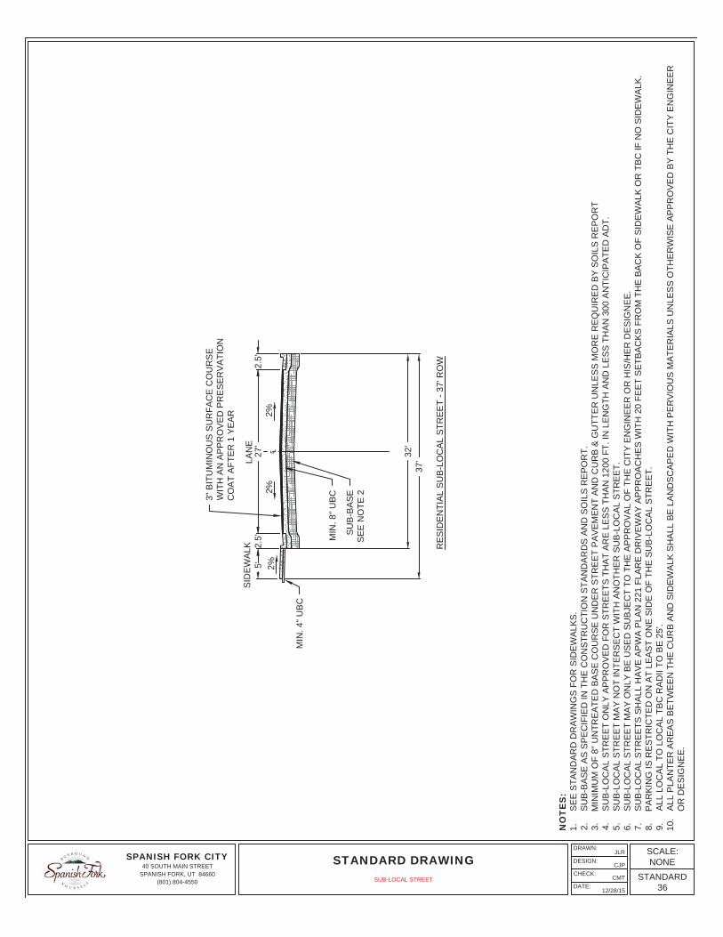
RE
SID
EN
TIA
L S
UB
-LO
CA
L S
TRE
ET
- 37'
RO
W
2%2%
2%5'
2.5'
27'
2.5'
32'
37'
SID
EW
ALK
LAN
E
℄
NO
TE
S:
1.S
EE
STA
ND
AR
D D
RA
WIN
GS
FO
R S
IDE
WA
LKS
.2.
SU
B-B
AS
E A
S S
PE
CIF
IED
IN T
HE
CO
NS
TRU
CTI
ON
STA
ND
AR
DS
AN
D S
OIL
S R
EP
OR
T.3.
MIN
IMU
M O
F 8"
UN
TRE
ATE
D B
AS
E C
OU
RS
E U
ND
ER
STR
EE
T P
AV
EM
EN
T A
ND
CU
RB
& G
UTT
ER
UN
LES
S M
OR
E R
EQ
UIR
ED
BY
SO
ILS
RE
PO
RT
4.S
UB
-LO
CA
L S
TRE
ET
ON
LY A
PP
RO
VE
D F
OR
STR
EE
TS T
HA
T A
RE
LE
SS
TH
AN
120
0 FT
. IN
LE
NG
TH A
ND
LE
SS
TH
AN
300
AN
TIC
IPA
TED
AD
T.5.
SU
B-L
OC
AL
STR
EE
T M
AY
NO
T IN
TER
SE
CT
WIT
H A
NO
THE
R S
UB
-LO
CA
L S
TRE
ET.
6.S
UB
-LO
CA
L S
TRE
ET
MA
Y O
NLY
BE
US
ED
SU
BJE
CT
TO T
HE
AP
PR
OV
AL
OF
THE
CIT
Y E
NG
INE
ER
OR
HIS
/HE
R D
ES
IGN
EE
.7.
SU
B-L
OC
AL
STR
EE
TS S
HA
LL H
AV
E A
PW
A P
LAN
221
FLA
RE
DR
IVE
WA
Y A
PP
RO
AC
HE
S W
ITH
20
FEE
T S
ETB
AC
KS
FR
OM
TH
E B
AC
K O
F S
IDE
WA
LK O
R T
BC
IF N
O S
IDE
WA
LK.
8.P
AR
KIN
G IS
RE
STR
ICTE
D O
N A
T LE
AS
T O
NE
SID
E O
F TH
E S
UB
-LO
CA
L S
TRE
ET.
9.A
LL L
OC
AL
TO L
OC
AL
TBC
RA
DII
TO B
E 2
5'.
10.
ALL
PLA
NTE
R A
RE
AS
BE
TWE
EN
TH
E C
UR
B A
ND
SID
EW
ALK
SH
ALL
BE
LA
ND
SC
AP
ED
WIT
H P
ER
VIO
US
MA
TER
IALS
UN
LES
S O
THE
RW
ISE
AP
PR
OV
ED
BY
TH
E C
ITY
EN
GIN
EE
RO
R D
ES
IGN
EE
.
MIN
. 4" U
BC
3" B
ITU
MIN
OU
S S
UR
FAC
E C
OU
RS
EW
ITH
AN
AP
PR
OV
ED
PR
ES
ER
VA
TIO
NC
OA
T A
FTE
R 1
YE
AR
MIN
. 8" U
BC
SU
B-B
AS
ES
EE
NO
TE 2
SPANISH FORK CITY40 SOUTH MAIN STREET
SPANISH FORK, UT 84660(801) 804-4550
DRAWN:
DESIGN:
CHECK:
DATE:
JLR
CJP
CMT
12/28/15
STANDARD DRAWINGSCALE:NONE
STANDARD36
SUB-LOCAL STREET
4'℄
11'
43'
90'
2%
LAN
ES
IDE
WA
LK
2%
21'
2.5'
SW
ALE
26'
2.5'
8'S
WA
LES
HO
ULD
ER
MIN
OR
CO
LLE
CTO
R 2
LA
NE
STR
EE
T - 9
0' R
OW
11'
2%
LAN
E8'
SH
OU
LDE
R
4" B
ITU
MIN
OU
S S
UR
FAC
EC
OU
RS
E W
ITH
AN
AP
PR
OV
ED
PR
ES
ER
VA
TIO
NC
OA
T A
FTE
R 1
YE
AR
6' M
AS
ON
RY
WA
LL
PLA
NTE
R
MIN
. 4" U
BC
SE
E L
OW
IMP
AC
TD
EV
ELO
PM
EN
T (L
ID)
CO
LLE
CTO
R/A
RTE
RIA
LS
TRE
ET
SW
ALE
STA
ND
AR
D
MIN
. 8" U
BC
SU
B-B
AS
ES
EE
NO
TE 6
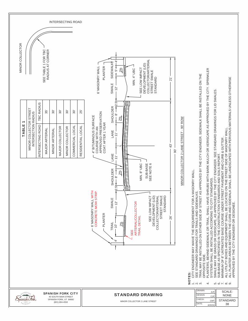
NO
TE
S:
1.C
ITY
EN
GIN
EE
R M
AY
WA
IVE
TH
E R
EQ
UIR
EM
EN
T FO
R A
MA
SO
NR
Y W
ALL
.2.
SE
E S
TAN
DA
RD
DR
AW
ING
S F
OR
TR
AIL
S A
ND
SID
EW
ALK
S.
3.TR
AIL
MA
Y B
E IN
STA
LLE
D O
N E
ITH
ER
SID
E O
F S
TRE
ET
AS
AP
PR
OV
ED
BY
TH
E C
ITY
EN
GIN
EE
R. S
IDE
WA
LK S
HA
LL B
E IN
STA
LLE
D O
N T
HE
OP
PO
SIT
E S
IDE
.4.
PLA
NTE
RS
, BE
HIN
D S
IDE
WA
LK O
R T
RA
IL, S
HA
LL H
AV
E S
HR
UB
S W
ITH
BA
RK
MU
LCH
OR
XE
RIS
CA
PE
AS
AP
PR
OV
ED
BY
TH
E C
ITY
. SP
RIN
KLE
RS
YS
TEM
S S
HA
LL B
E IN
STA
LLE
D A
CC
OR
DIN
G T
O C
ITY
STA
ND
AR
DS
.5.
SW
ALE
MA
Y B
E G
RA
SS
OR
XE
RIS
CA
PE
, AS
AP
PR
OV
ED
BY
TH
E C
ITY
EN
GIN
EE
R. S
EE
STA
ND
AR
D D
RA
WIN
GS
FO
R L
ID S
WA
LES
.6.
SU
B-B
AS
E A
S S
PE
CIF
IED
IN T
HE
CO
NS
TRU
CTI
ON
STA
ND
AR
DS
AN
D S
OIL
S R
EP
OR
T.7.
MIN
IMU
M O
F 8"
UN
TRE
ATE
D B
AS
E C
OU
RS
E U
ND
ER
STR
EE
T P
AV
EM
EN
T A
ND
CU
RB
& G
UTT
ER
.8.
ALL
UTI
LITY
BO
XE
S A
ND
EQ
UIP
ME
NT
SH
ALL
BE
LO
CA
TED
ON
TH
E S
TRE
ET
SID
E O
F M
AS
ON
RY
WA
LL.
9.A
LL P
LAN
TER
AR
EA
S B
ETW
EE
N T
HE
CU
RB
AN
D S
IDE
WA
LK S
HA
LL B
E L
AN
DS
CA
PE
D W
ITH
PE
RV
IOU
S M
ATE
RIA
LS U
NLE
SS
OTH
ER
WIS
EA
PP
RO
VE
D B
Y T
HE
CIT
Y E
NG
INE
ER
OR
DE
SIG
NE
E.
SE
E T
AB
LE 1
FO
R T
BC
RA
DIU
S A
T C
OR
NE
R
TA
BLE
1M
INO
R C
OLL
EC
TOR
STR
EE
TIN
TER
SE
CTI
ON
RA
DIU
S
INTE
RS
EC
TIN
G R
OA
DTB
C R
AD
IUS
MA
JOR
AR
TER
IAL
35'
MIN
OR
AR
TER
IAL
30'
MA
JOR
CO
LLE
CTO
R30
'
MIN
OR
CO
LLE
CTO
R30
'
CO
MM
ER
CIA
L LO
CA
L30
'
RE
SID
EN
TIA
L LO
CA
L25
'
INTERSECTING ROADM
INO
R C
OLL
EC
TOR
12'
12'
5'10
'TR
AIL 2%
4'
PLA
NTE
R
6' M
AS
ON
RY
WA
LL W
ITH
CO
NC
RE
TE M
OW
STR
IP
SE
EA
RTE
RIA
L/C
OLL
EC
TOR
TRA
IL D
ETA
IL
SE
E L
OW
IMP
AC
TD
EV
ELO
PM
EN
T (L
ID)
CO
LLE
CTO
R/A
RTE
RIA
LS
TRE
ET
SW
ALE
STA
ND
AR
D
SPANISH FORK CITY40 SOUTH MAIN STREET
SPANISH FORK, UT 84660(801) 804-4550
DRAWN:
DESIGN:
CHECK:
DATE:
JLR
CJP
CMT
4/20/16
STANDARD DRAWINGSCALE:NONE
STANDARD38
MINOR COLLECTOR 2 LANE STREET
℄2%
2%
LAN
EM
ED
IAN
/LA
NE
LAN
ES
IDE
WA
LK
2%
2.5'
SW
ALE
SH
OU
LDE
R5'
2.5'
SW
ALE
2%
SH
OU
LDE
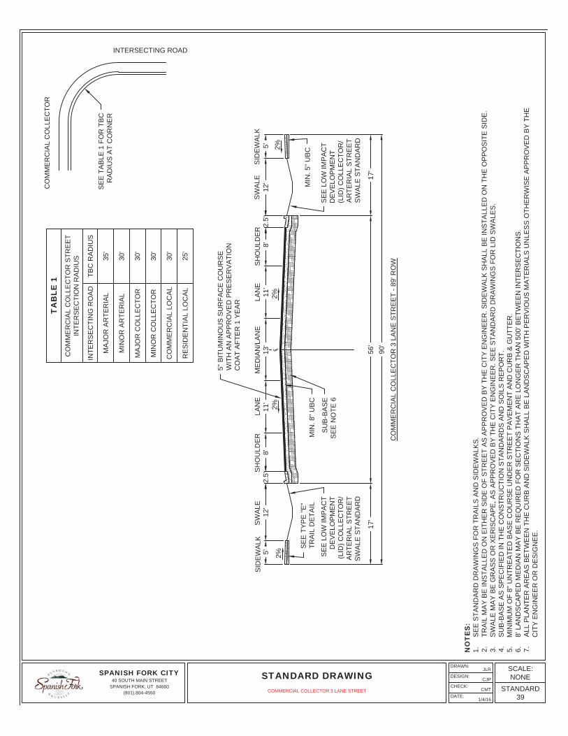
R CO
MM
ER
CIA
L C
OLL
EC
TOR
3 L
AN
E S
TRE
ET
- 89'
RO
W
NO
TE
S:
1.S
EE
STA
ND
AR
D D
RA
WIN
GS
FO
R T
RA
ILS
AN
D S
IDE
WA
LKS
.2.
TRA
IL M
AY
BE
INS
TALL
ED
ON
EIT
HE
R S
IDE
OF
STR
EE
T A
S A
PP
RO
VE
D B
Y T
HE
CIT
Y E
NG
INE
ER
. SID
EW
ALK
SH
ALL
BE
INS
TALL
ED
ON
TH
E O
PP
OS
ITE
SID
E.
3.S
WA
LE M
AY
BE
GR
AS
S O
R X
ER
ISC
AP
E, A
S A
PP
RO
VE
D B
Y T
HE
CIT
Y E
NG
INE
ER
. SE
E S
TAN
DA
RD
DR
AW
ING
S F
OR
LID
SW
ALE
S.
4.S
UB
-BA
SE
AS
SP
EC
IFIE
D IN
TH
E C
ON
STR
UC
TIO
N S
TAN
DA
RD
S A
ND
SO
ILS
RE
PO
RT.
5.M
INIM
UM
OF
8" U
NTR
EA
TED
BA
SE
CO
UR
SE
UN
DE
R S
TRE
ET
PA
VE
ME
NT
AN
D C
UR
B &
GU
TTE
R.
6.8'
LA
ND
SC
AP
ED
ME
DIA
N M
AY
BE
RE
QU
IRE
D F
OR
SE
CTI
ON
S T
HA
T A
RE
LO
NG
ER
TH
AN
500
' BE
TWE
EN
INTE
RS
EC
TIO
NS
.7.
ALL
PLA
NTE
R A
RE
AS
BE
TWE
EN
TH
E C
UR
B A
ND
SID
EW
ALK
SH
ALL
BE
LA
ND
SC
AP
ED
WIT
H P
ER
VIO
US
MA
TER
IALS
UN
LES
S O
THE
RW
ISE
AP
PR
OV
ED
BY
TH
EC
ITY
EN
GIN
EE
R O
R D
ES
IGN
EE
.
5" B
ITU
MIN
OU
S S
UR
FAC
E C
OU
RS
EW
ITH
AN
AP
PR
OV
ED
PR
ES
ER
VA
TIO
NC
OA
T A
FTE
R 1
YE
AR
MIN
. 5" U
BC
SE
E L
OW
IMP
AC
TD
EV
ELO
PM
EN
T(L
ID) C
OLL
EC
TOR
/A
RTE
RIA
L S
TRE
ET
SW
ALE
STA
ND
AR
D
SE
E T
AB
LE 1
FO
R T
BC
RA
DIU
S A
T C
OR
NE
R
TA
BLE
1C
OM
ME
RC
IAL
CO
LLE
CTO
R S
TRE
ET
INTE
RS
EC
TIO
N R
AD
IUS
INTE
RS
EC
TIN
G R
OA
DTB
C R
AD
IUS
MA
JOR
AR
TER
IAL
35'
MIN
OR
AR
TER
IAL
30'
MA
JOR
CO
LLE
CTO
R30
'
MIN
OR
CO
LLE
CTO
R30
'
CO
MM
ER
CIA
L LO
CA
L30
'
RE
SID
EN
TIA
L LO
CA
L25
'
INTERSECTING ROADC
OM
ME
RC
IAL
CO
LLE
CTO
R
MIN
. 8" U
BC
SU
B-B
AS
ES
EE
NO
TE 6
11'
13'
11'
56'
90'
17'
12'
8'
17'12
'8'
5'
SE
E T
YP
E "E
"TR
AIL
DE
TAIL
SID
EW
ALK
SE
E L
OW
IMP
AC
TD
EV
ELO
PM
EN
T(L
ID) C
OLL
EC
TOR
/A
RTE
RIA
L S
TRE
ET
SW
ALE
STA
ND
AR
D
SPANISH FORK CITY40 SOUTH MAIN STREET
SPANISH FORK, UT 84660(801) 804-4550
DRAWN:
DESIGN:
CHECK:
DATE:
JLR
CJP
CMT
1/4/16
STANDARD DRAWINGSCALE:NONE
STANDARD39
COMMERCIAL COLLECTOR 3 LANE STREET
℄2%
2%
LAN
EM
ED
IAN
/LA
NE
LAN
ES
IDE
WA
LK
2%2.
5'S
WA
LES
HO
ULD
ER
10'
2.5'
TRA
ILS
WA
LES
HO
ULD
ER
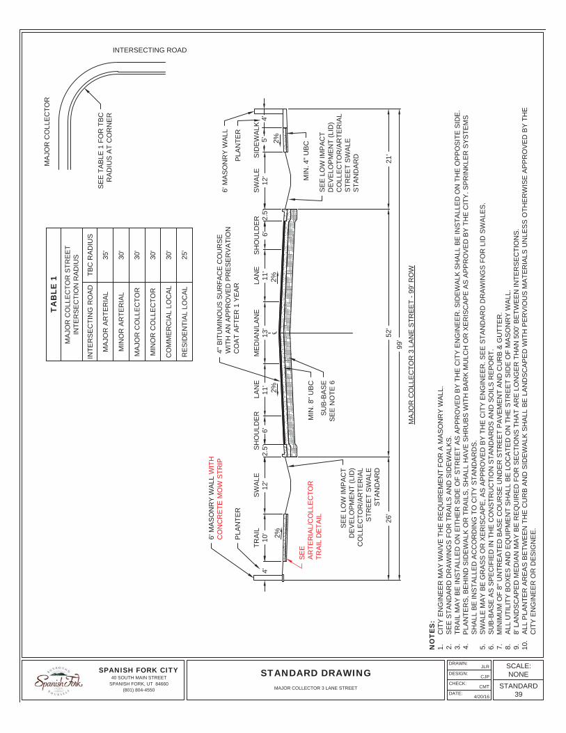
MA
JOR
CO
LLE
CTO
R 3
LA
NE
STR
EE
T - 9
9' R
OW
NO
TE
S:
1.C
ITY
EN
GIN
EE
R M
AY
WA
IVE
TH
E R
EQ
UIR
EM
EN
T FO
R A
MA
SO
NR
Y W
ALL
.2.
SE
E S
TAN
DA
RD
DR
AW
ING
S F
OR
TR
AIL
S A
ND
SID
EW
ALK
S.
3.TR
AIL
MA
Y B
E IN
STA
LLE
D O
N E
ITH
ER
SID
E O
F S
TRE
ET
AS
AP
PR
OV
ED
BY
TH
E C
ITY
EN
GIN
EE
R. S
IDE
WA
LK S
HA
LL B
E IN
STA
LLE
D O
N T
HE
OP
PO
SIT
E S
IDE
.4.
PLA
NTE
RS
, BE
HIN
D S
IDE
WA
LK O
R T
RA
ILS
, SH
ALL
HA
VE
SH
RU
BS
WIT
H B
AR
K M
ULC
H O
R X
ER
ISC
AP
E A
S A
PP
RO
VE
D B
Y T
HE
CIT
Y. S
PR
INK
LER
SY
STE
MS
SH
ALL
BE
INS
TALL
ED
AC
CO
RD
ING
TO
CIT
Y S
TAN
DA
RD
S.
5.S
WA
LE M
AY
BE
GR
AS
S O
R X
ER
ISC
AP
E, A
S A
PP
RO
VE
D B
Y T
HE
CIT
Y E
NG
INE
ER
. SE
E S
TAN
DA
RD
DR
AW
ING
S F
OR
LID
SW
ALE
S.
6.S
UB
-BA
SE
AS
SP
EC
IFIE
D IN
TH
E C
ON
STR
UC
TIO
N S
TAN
DA
RD
S A
ND
SO
ILS
RE
PO
RT.
7.M
INIM
UM
OF
8" U
NTR
EA
TED
BA
SE
CO
UR
SE
UN
DE
R S
TRE
ET
PA
VE
ME
NT
AN
D C
UR
B &
GU
TTE
R.
8.A
LL U
TILI
TY B
OX
ES
AN
D E
QU
IPM
EN
T S
HA
LL B
E L
OC
ATE
D O
N T
HE
STR
EE
T S
IDE
OF
MA
SO
NR
Y W
ALL
.9.
8' L
AN
DS
CA
PE
D M
ED
IAN
MA
Y B
E R
EQ
UIR
ED
FO
R S
EC
TIO
NS
TH
AT
AR
E L
ON
GE
R T
HA
N 5
00' B
ETW
EE
N IN
TER
SE
CTI
ON
S.
10.
ALL
PLA
NTE
R A
RE
AS
BE
TWE
EN
TH
E C
UR
B A
ND
SID
EW
ALK
SH
ALL
BE
LA
ND
SC
AP
ED
WIT
H P
ER
VIO
US
MA
TER
IALS
UN
LES
S O
THE
RW
ISE
AP
PR
OV
ED
BY
TH
EC
ITY
EN
GIN
EE
R O
R D
ES
IGN
EE
.
4" B
ITU
MIN
OU
S S
UR
FAC
E C
OU
RS
EW
ITH
AN
AP
PR
OV
ED
PR
ES
ER
VA
TIO
NC
OA
T A
FTE
R 1
YE
AR
6' M
AS
ON
RY
WA
LL
PLA
NTE
R
MIN
. 4" U
BC
SE
E L
OW
IMP
AC
TD
EV
ELO
PM
EN
T (L
ID)
CO
LLE
CTO
R/A
RTE
RIA
LS
TRE
ET
SW
ALE
STA
ND
AR
D
SE
E T
AB
LE 1
FO
R T
BC
RA
DIU
S A
T C
OR
NE
R
TA
BLE
1M
AJO
R C
OLL
EC
TOR
STR
EE
TIN
TER
SE
CTI
ON
RA
DIU
S
INTE
RS
EC
TIN
G R
OA
DTB
C R
AD
IUS
MA
JOR
AR
TER
IAL
35'
MIN
OR
AR
TER
IAL
30'
MA
JOR
CO
LLE
CTO
R30
'
MIN
OR
CO
LLE
CTO
R30
'
CO
MM
ER
CIA
L LO
CA
L30
'
RE
SID
EN
TIA
L LO
CA
L25
'
INTERSECTING ROADM
AJO
R C
OLL
EC
TOR
MIN
. 8" U
BC
SU
B-B
AS
ES
EE
NO
TE 6
11'
13'
11'
52'
99'
21'
12'
6'
26'
12'
6'4'
5'
2%
4'
PLA
NTE
R
6' M
AS
ON
RY
WA
LL W
ITH
CO
NC
RE
TE M
OW
STR
IP
SE
EA
RTE
RIA
L/C
OLL
EC
TOR
TRA
IL D
ETA
IL
SE
E L
OW
IMP
AC
TD
EV
ELO
PM
EN
T (L
ID)
CO
LLE
CTO
R/A
RTE
RIA
LS
TRE
ET
SW
ALE
STA
ND
AR
D
SPANISH FORK CITY40 SOUTH MAIN STREET
SPANISH FORK, UT 84660(801) 804-4550
DRAWN:
DESIGN:
CHECK:
DATE:
JLR
CJP
CMT
4/20/16
STANDARD DRAWINGSCALE:NONE
STANDARD39
MAJOR COLLECTOR 3 LANE STREET
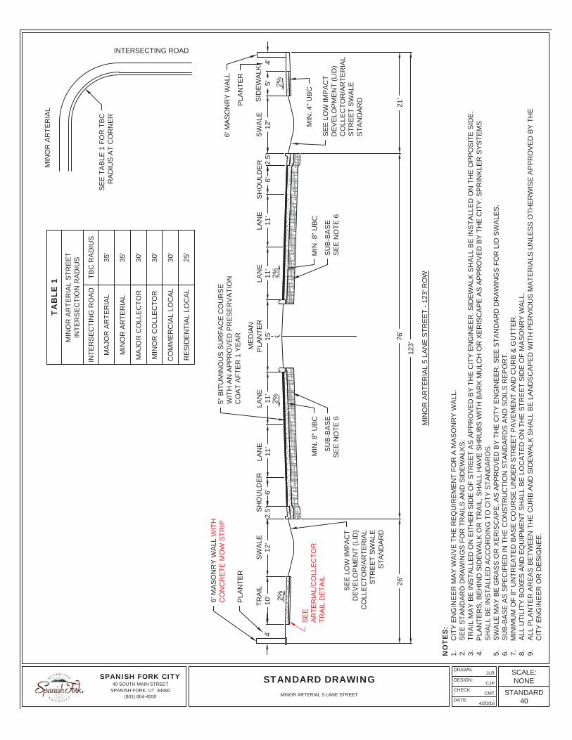
26'
10'
12'
2.5'
6'11
'15
'4'
76'
123'
TRA
ILS
WA
LELA
NE
ME
DIA
NP
LAN
TER
SID
EW
ALK
℄2%
2%2%
4'S
HO
ULD
ER
11'
LAN
E
21'
12'
2.5'
6'11
'S
WA
LELA
NE
2%
SH
OU
LDE
R11
'LA
NE
MIN
OR
AR
TER
IAL
5 LA
NE
STR
EE
T - 1
23' R
OW
NO
TE
S:
1.C
ITY
EN
GIN
EE
R M
AY
WA
IVE
TH
E R
EQ
UIR
EM
EN
T FO
R A
MA
SO
NR
Y W
ALL
.2.
SE
E S
TAN
DA
RD
DR
AW
ING
S F
OR
TR
AIL
S A
ND
SID
EW
ALK
S.
3.TR
AIL
MA
Y B
E IN
STA
LLE
D O
N E
ITH
ER
SID
E O
F S
TRE
ET
AS
AP
PR
OV
ED
BY
TH
E C
ITY
EN
GIN
EE
R. S
IDE
WA
LK S
HA
LL B
E IN
STA
LLE
D O
N T
HE
OP
PO
SIT
E S
IDE
.4.
PLA
NTE
RS
, BE
HIN
D S
IDE
WA
LK O
R T
RA
IL, S
HA
LL H
AV
E S
HR
UB
S W
ITH
BA
RK
MU
LCH
OR
XE
RIS
CA
PE
AS
AP
PR
OV
ED
BY
TH
E C
ITY
. SP
RIN
KLE
R S
YS
TEM
SS
HA
LL B
E IN
STA
LLE
D A
CC
OR
DIN
G T
O C
ITY
STA
ND
AR
DS
.5.
SW
ALE
MA
Y B
E G
RA
SS
OR
XE
RIS
CA
PE
, AS
AP
PR
OV
ED
BY
TH
E C
ITY
EN
GIN
EE
R. S
EE
STA
ND
AR
D D
RA
WIN
GS
FO
R L
ID S
WA
LES
.6.
SU
B-B
AS
E A
S S
PE
CIF
IED
IN T
HE
CO
NS
TRU
CTI
ON
STA
ND
AR
DS
AN
D S
OIL
S R
EP
OR
T.7.
MIN
IMU
M O
F 8"
UN
TRE
ATE
D B
AS
E C
OU
RS
E U
ND
ER
STR
EE
T P
AV
EM
EN
T A
ND
CU
RB
& G
UTT
ER
.8.
ALL
UTI
LITY
BO
XE
S A
ND
EQ
UIP
ME
NT
SH
ALL
BE
LO
CA
TED
ON
TH
E S
TRE
ET
SID
E O
F M
AS
ON
RY
WA
LL.
9.A
LL P
LAN
TER
AR
EA
S B
ETW
EE
N T
HE
CU
RB
AN
D S
IDE
WA
LK S
HA
LL B
E L
AN
DS
CA
PE
D W
ITH
PE
RV
IOU
S M
ATE
RIA
LS U
NLE
SS
OTH
ER
WIS
E A
PP
RO
VE
D B
Y T
HE
CIT
Y E
NG
INE
ER
OR
DE
SIG
NE
E.
PLA
NTE
R
6' M
AS
ON
RY
WA
LL
PLA
NTE
R
5" B
ITU
MIN
OU
S S
UR
FAC
E C
OU
RS
EW
ITH
AN
AP
PR
OV
ED
PR
ES
ER
VA
TIO
NC
OA
T A
FTE
R 1
YE
AR
MIN
. 4" U
BC
SE
E L
OW
IMP
AC
TD
EV
ELO
PM
EN
T (L
ID)
CO
LLE
CTO
R/A
RTE
RIA
LS
TRE
ET
SW
ALE
STA
ND
AR
D
MIN
. 8" U
BC
SU
B-B
AS
ES
EE
NO
TE 6
SE
E T
AB
LE 1
FO
R T
BC
RA
DIU
S A
T C
OR
NE
R
TA
BLE
1M
INO
R A
RTE
RIA
L S
TRE
ET
INTE
RS
EC
TIO
N R
AD
IUS
INTE
RS
EC
TIN
G R
OA
DTB
C R
AD
IUS
MA
JOR
AR
TER
IAL
35'
MIN
OR
AR
TER
IAL
35'
MA
JOR
CO
LLE
CTO
R30
'
MIN
OR
CO
LLE
CTO
R30
'
CO
MM
ER
CIA
L LO
CA
L30
'
RE
SID
EN
TIA
L LO
CA
L25
'
INTERSECTING ROADM
INO
R A
RTE
RIA
L
MIN
. 8" U
BC
SU
B-B
AS
ES
EE
NO
TE 6
5'
6' M
AS
ON
RY
WA
LL W
ITH
CO
NC
RE
TE M
OW
STR
IP
SE
EA
RTE
RIA
L/C
OLL
EC
TOR
TRA
IL D
ETA
IL
SE
E L
OW
IMP
AC
TD
EV
ELO
PM
EN
T (L
ID)
CO
LLE
CTO
R/A
RTE
RIA
LS
TRE
ET
SW
ALE
STA
ND
AR
D
SPANISH FORK CITY40 SOUTH MAIN STREET
SPANISH FORK, UT 84660(801) 804-4550
DRAWN:
DESIGN:
CHECK:
DATE:
JLR
CJP
CMT
4/20/16
STANDARD DRAWINGSCALE:NONE
STANDARD40
MINOR ARTERIAL 5 LANE STREET
TRA
ILM
ED
IAN
PLA
NTE
RLA
NE
SH
OU
LDE
R/
FUTU
RE
LA
NE
SW
ALE
SID
EW
ALK
10'
138'
26'
91'
21'
2%℄
2%4'
LAN
ELA
NE
SH
OU
LDE
R/
FUTU
RE
LA
NE
SW
ALE
2%
LAN
E12
'2.
5'13
.5'
11'
11'
15'
11'
11'
13.5
'2.
5'12
'
2%
MA
JOR
AR
TER
IAL
7 LA
NE
STR
EE
T - 1
38' R
OW
NO
TE
S:
1.C
ITY
EN
GIN
EE
R M
AY
WA
IVE
TH
E R
EQ
UIR
EM
EN
T FO
R A
MA
SO
NR
Y W
ALL
.2.
SE
E S
TAN
DA
RD
DR
AW
ING
S F
OR
TR
AIL
S A
ND
SID
EW
ALK
S.
3.TR
AIL
MA
Y B
E IN
STA
LLE
D O
N E
ITH
ER
SID
E O
F S
TRE
ET
AS
AP
PR
OV
ED
BY
TH
E C
ITY
EN
GIN
EE
R. S
IDE
WA
LK S
HA
LL B
E IN
STA
LLE
D O
N T
HE
OP
PO
SIT
E S
IDE
.4.
PLA
NTE
RS
, BE
HIN
D S
IDE
WA
LK O
R T
RA
ILS
, SH
ALL
HA
VE
SH
RU
BS
WIT
H B
AR
K M
ULC
H O
R X
ER
ISC
AP
E A
S A
PP
RO
VE
D B
Y T
HE
CIT
Y. S
PR
INK
LER
SY
STE
MS
SH
ALL
BE
INS
TALL
ED
AC
CO
RD
ING
TO
CIT
Y S
TAN
DA
RD
S.
5.S
WA
LE M
AY
BE
GR
AS
S O
R X
ER
ISC
AP
E, A
S A
PP
RO
VE
D B
Y T
HE
CIT
Y E
NG
INE
ER
. SE
E S
TAN
DA
RD
DR
AW
ING
S F
OR
LID
SW
ALE
S.
6.S
UB
-BA
SE
AS
SP
EC
IFIE
D IN
TH
E C
ON
STR
UC
TIO
N S
TAN
DA
RD
S A
ND
SO
ILS
RE
PO
RT.
7.M
INIM
UM
OF
8" U
NTR
EA
TED
BA
SE
CO
UR
SE
UN
DE
R S
TRE
ET
PA
VE
ME
NT
AN
D C
UR
B &
GU
TTE
R.
8.A
LL U
TILI
TY B
OX
ES
AN
D E
QU
IPM
EN
T S
HA
LL B
E L
OC
ATE
D O
N T
HE
STR
EE
T S
IDE
OF
MA
SO
NR
Y W
ALL
.9.
ALL
PLA
NTE
R A
RE
AS
BE
TWE
EN
TH
E C
UR
B A
ND
SID
EW
ALK
SH
ALL
BE
LA
ND
SC
AP
ED
WIT
H P
ER
VIO
US
MA
TER
IALS
UN
LES
S O
THE
RW
ISE
AP
PR
OV
ED
BY
TH
EC
ITY
EN
GIN
EE
R O
R D
ES
IGN
EE
.
6' M
AS
ON
RY
WA
LLP
LAN
TER
6' M
AS
ON
RY
WA
LL W
ITH
CO
NC
RE
TE M
OW
STR
IP
PLA
NTE
R
5" B
ITU
MIN
OU
S S
UR
FAC
E C
OU
RS
EW
ITH
AN
AP
PR
OV
ED
PR
ES
ER
VA
TIO
NC
OA
T A
FTE
R 1
YE
AR
MIN
. 4" U
BC
SE
E L
OW
IMP
AC
TD
EV
ELO
PM
EN
T (L
ID)
CO
LLE
CTO
R/A
RTE
RIA
LS
TRE
ET
SW
ALE
STA
ND
AR
D
SE
E T
AB
LE 1
FO
R T
BC
RA
DIU
S A
T C
OR
NE
R
TA
BLE
1M
AJO
R A
RTE
RIA
L S
TRE
ET
INTE
RS
EC
TIO
N R
AD
IUS
INTE
RS
EC
TIN
G R
OA
DTB
C R
AD
IUS
MA
JOR
AR
TER
IAL
35'
MIN
OR
AR
TER
IAL
35'
MA
JOR
CO
LLE
CTO
R35
'
MIN
OR
CO
LLE
CTO
R35
'
CO
MM
ER
CIA
L LO
CA
L30
'
RE
SID
EN
TIA
L LO
CA
L25
'
INTERSECTING ROADM
AJO
R A
RTE
RIA
L
MIN
. 8" U
BC
SU
B-B
AS
ES
EE
NO
TE 6
MIN
. 8" U
BC
SU
B-B
AS
ES
EE
NO
TE 6
5'4'
SE
EA
RTE
RIA
L/C
OLL
EC
TOR
TRA
IL D
ETA
IL
SE
E L
OW
IMP
AC
TD
EV
ELO
PM
EN
T (L
ID)
CO
LLE
CTO
R/A
RTE
RIA
LS
TRE
ET
SW
ALE
STA
ND
AR
D
SPANISH FORK CITY40 SOUTH MAIN STREET
SPANISH FORK, UT 84660(801) 804-4550
DRAWN:
DESIGN:
CHECK:
DATE:
JLR
CJP
CMT
4/20/16
STANDARD DRAWINGSCALE:NONE
STANDARD41
MAJOR ARTERIAL 7 LANE STREET
NO
TE
S:
1.TH
IS T
RA
IL L
AY
OU
T M
AY
ON
LY B
E U
SE
D W
HE
N A
UTH
OR
IZE
D B
Y T
HE
CIT
Y E
NG
INE
ER
.2.
TRA
IL L
AN
ES
SH
ALL
BE
DE
LIN
EA
TED
BY
A C
EN
TER
, SIN
GLE
, DA
SH
ED
, YE
LLO
W L
INE
.3.
BO
XE
S S
HA
LL B
E P
LAC
ED
ON
PR
OP
ER
TY L
INE
S W
HE
RE
EV
ER
PO
SS
IBLE
.
SE
CTI
ON
A-A
SE
CTI
ON
B-B
10'
1 1/
2 TO
2%
FA
LLFR
OM
WA
LL T
O C
UR
B
10' TY
PE
"A" T
RA
IL
WA
LLW
ALL
SE
CTI
ON
ALI
ZER
STA
ND
AR
DLI
GH
T P
OLE
TYP
E "A
" TR
AIL
1 1/
2 TO
2%
FA
LLFR
OM
WA
LL T
O C
UR
B
STA
ND
AR
D L
IGH
T P
OLE
CO
MM
UN
ICA
TIO
N B
OX
ES
PA
VE
AR
OU
ND
UTI
LITY
BO
XE
S &
LIG
HT
10' W
ALL
SE
CTI
ON
SE
LEC
TRIC
AL
&C
OM
MU
NIC
ATI
ON
CO
ND
UIT
YE
LLO
W S
OLI
D L
INE
CU
RB
AN
D G
UTT
ER
YE
LLO
W S
KIP
LIN
E
AA
BB
4'5'
10'
8'
SPANISH FORK CITY40 SOUTH MAIN STREET
SPANISH FORK, UT 84660(801) 804-4550
DRAWN:
DESIGN:
CHECK:
DATE:
JLR
CJP
CMT
4/20/16
STANDARD DRAWINGSCALE:NONE
STANDARD44
CURB SIDE TRAIL LAYOUT
DELETE
24" CATCH CURB AND GUTTER
24"
FLOW AWAY CURB AND GUTTER
18"
12"
12"
2"
10"
24"
24" DRIVE THROUGH GUTTERSEE NOTE 9
12"
12"
12"
1"
6" 24"
31 2"
7"
212"
6"
13"
7" 23"
30" CATCH CURB AND GUTTER
12"
12"
12"
6"2"
712"
30"8"
30" DRIVE THROUGH GUTTERSEE NOTE 9
CROSS GUTTER
48"
NOTES:1. SUB-BASE UNDER ALL CURBS AND GUTTERS SHALL MATCH WHAT IS IN THE ROAD WITH A MINIMUM OF 8" OF COMPACTED UNTREATED BASE
COURSE.2. IF CONCRETE IS TO BE POURED NEXT TO A CURB #4 REBAR SHALL BE DOWELED 3" INTO CURB AND 4" INTO SIDEWALK. REBAR SHALL BE
INSTALLED A MINIMUM OF 2" FROM TOP OF SIDEWALK AND CURB 24" O.C.3. SIDEWALKS SHALL HAVE CONSTRUCTION JOINTS EVERY 5'.4. TOP FRONT OF SIDEWALK SHALL BE PLACED AT THE SAME GRADE AS TOP BACK OF CURB.5. TACK SHALL BE APPLIED TO LIP OF CURB AND EXTEND 1' ONTO GRAVEL ROAD BASE.6. PAVERS, FABRIC, SAND MATERIAL AND INSTALLATION SHALL MEET THE SPECIFICATIONS AND REQUIREMENTS OF APWA 32 14 13 (PRECAST
CONCRETE UNIT PAVING) AND 32 14 16 (BRICK UNIT PAVING).7. ESTABLISH PAVER PATTERN TO ASSURE ALL CUT EDGE PAVERS SHALL BE HALF PAVERS OR LARGER.8. ALL PAVERS SHALL MATCH THE ORGINAL COLOR OF THE DARK RED CONCRETE PAVERS ON MAIN STREET9. MODIFIED CURB & GUTTER IS ONLY TO BE USED IN THE RESIDENTIAL SUB LOCAL ROAD - 42' RIGHT OF WAY UNLESS OTHERWISE APPROVED
BY THE CITY ENGINEER.
R3/4" (TYP)
6"
8"
8"61 2"
APWA TYPE "E" CURB ANDGUTTER AS MODIFIED
BACKFILL BEHIND CURBBEFORE PAVING
# 4 REB A R @ 2 4 " O .C .
(5) #4 REBAR @ 10 1/2" O.C.
MIN. 8" UNTREATED BASECOURSE UNLESS MORE
REQUIRED BY SOILSREPORT (TYP)
SUB-BASE AS SPECIFIED IN THECONSTRUCTION STANDARDS AND
SOILS REPORT (TYP)
MIN. 8" UNTREATED BASECOURSE UNLESS MORE
REQUIRED BY SOILSREPORT (TYP)
SUB-BASE AS SPECIFIED IN THECONSTRUCTION STANDARDS AND
SOILS REPORT (TYP)
MIN. 8" UNTREATED BASECOURSE UNLESS MORE
REQUIRED BY SOILSREPORT (TYP)
SUB-BASE AS SPECIFIED IN THECONSTRUCTION STANDARDS AND
SOILS REPORT (TYP)
APWA 4' WATERWAY
734"
9"
TYPE "D" CURBAND GUTTERR=1"
R=12"
BACKFILL BEHIND CURBBEFORE PAVING R3
4" (TYP)
APWA TYPE "E"CURB AND GUTTER
BACKFILL BEHINDCURB BEFORE PAVING
APWA TYPE "B1"CURB AND GUTTER
BACKFILL BEHINDCURB BEFORE PAVING
4"
SPANISH FORK CITY40 SOUTH MAIN STREET
SPANISH FORK, UT 84660(801) 804-4550
DRAWN:
DESIGN:
CHECK:
DATE:
JLR
CJP
CMT
3/30/16
STANDARD DRAWINGSCALE:NONE
STANDARD45
CURB & GUTTERS
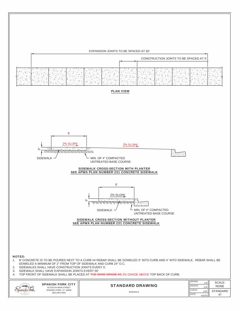
NOTES:1. IF CONCRETE IS TO BE POURED NEXT TO A CURB #4 REBAR SHALL BE DOWELED 3" INTO CURB AND 4" INTO SIDEWALK. REBAR SHALL BE
DOWELED A MINIMUM OF 2" FROM TOP OF SIDEWALK AND CURB 24" O.C.2. SIDEWALKS SHALL HAVE CONSTRUCTION JOINTS EVERY 5'.3. SIDEWALK SHALL HAVE EXPANSION JOINTS EVERY 50'4. TOP FRONT OF SIDEWALK SHALL BE PLACED AT THE SAME GRADE AS 2% GRADE ABOVE TOP BACK OF CURB.
CONSTRUCTION JOINTS TO BE SPACED AT 5'
PLAN VIEW
EXPANSION JOINTS TO BE SPACED AT 50'
MIN. OF 4" COMPACTEDUNTREATED BASE COURSE
2% SLOPE
5'
5"
SIDEWALK CROSS-SECTION WITH PLANTERSEE APWA PLAN NUMBER 231 CONCRETE SIDEWALK
MIN. OF 4" COMPACTEDUNTREATED BASE COURSE
5"
SIDEWALK CROSS-SECTION WITHOUT PLANTERSEE APWA PLAN NUMBER 231 CONCRETE SIDEWALK
SIDEWALK
SIDEWALK
2% SLOPE
5'
2% SLOPE
SPANISH FORK CITY40 SOUTH MAIN STREET
SPANISH FORK, UT 84660(801) 804-4550
DRAWN:
DESIGN:
CHECK:
DATE:
JLR
CJP
CMT
4/20/16
STANDARD DRAWINGSCALE:NONE
STANDARD47
SIDEWALK
8'
8'
BEGINNING OF CURVE TBC
23'
CAST-IRON DETECTABLEWARNING RADIUS PLATE (TYP.)
29'
8'
11'
23'5'
3' 20'
2'-6
"
10' RADIUS
TBC 25' RADIUS
11'
5' 2'
5'
2'
FULL HEIGHT CURBFULL HEIGHT CURB
NO LIP AT CURBCUT OR GUTTER
CAST-IRON DETECTABLEWARNING RADIUS PLATE (TYP.)
5'
RAMP
3'
11'
NOTES:1. RAMPS SHALL HAVE A 1:12 MAXIMUM SLOPE, WITH A MAXIMUM 2% CROSS SLOPE. ALL OTHER SIDEWALK SHALL HAVE A 1:48 MAXIMUM CROSS
SLOPE.2. CONTRACTOR SHALL INSTALL CAST-IRON DETECTABLE WARNING RADIUS PLATES. PLATES SHALL BE AN EAST JORDAN IRON WORKS OR
APPROVED EQUIVALENT. DETECTABLE WARNING PLATES SHALL CONSIST OF RAISED TRUNCATED DOMES WITH A DIAMETER OF NOMINAL 0.9",A HEIGHT OF NOMINAL 0.2" AND A CENTER-TO-CENTER SPACING OF NOMINAL 2.35".
3. LOCATE DETECTABLE WARNING SURFACE SO THE CORNERS NEAREST THE STREET ARE WITHIN 1" OF THE BACK OF CURB.4. CONCRETE SHALL BE 5" THICK THROUGHOUT RAMP.5. RAMP THAT IS TO BE POURED NEXT TO A CURB, SHALL HAVE #4 REBAR SHALL BE DOWELED 6" INTO CURB AND 12" INTO RAMP. REBAR SHALL
BE INSTALLED A MINIMUM OF 2" FROM TOP OF CURB 24" O.C.6. CURB FLARE SHALL HAVE A 1:4 MAXIMUM SLOPE. MODIFICATIONS TO THIS STANDARD MUST BE APPROVED BY THE CITY.7. REDUCED WIDTH INTERSECTION TO BE USED WITH LOCAL TO LOCAL ROADS. NOT TO BE USED WITH COLLECTOR/ ARTERIAL ROADS.
LOCAL-TO-LOCAL TEE INTERSECTION
CORNER DETAIL
RADIUS PLATE (TYP.)
29'
6' FLARETBC 100' R
(TYP.)
TBC 100' R(TYP.)
SPANISH FORK CITY40 SOUTH MAIN STREET
SPANISH FORK, UT 84660(801) 804-4550
DRAWN:
DESIGN:
CHECK:
DATE:
JLR
CJP
CMT
4/21/16
STANDARD DRAWINGSCALE:NONE
STANDARD48 59
REDUCED WIDTH INTERSECTION (LOCAL TO LOCAL)
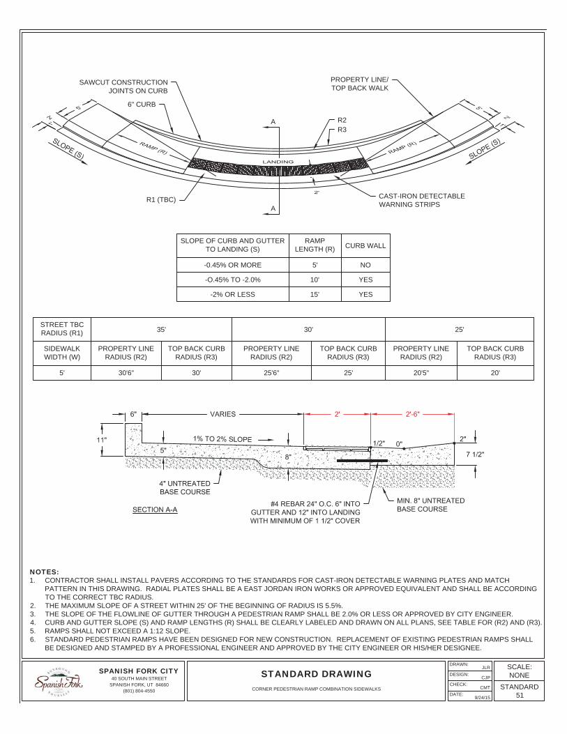
VARIES 2'
8"
6" 2'-6"
11"
8"
SECTION A-A
5"
SLOPE OF CURB AND GUTTERTO LANDING (S)
RAMPLENGTH (R) CURB WALL
-0.45% OR MORE 5' NO
-O.45% TO -2.0% 10' YES
-2% OR LESS 15' YES
STREET TBC RADIUS (R1) 35' RADIUS 30' RADIUS 25' RADIUS
SIDEWALK WIDTH
(W1)
PLANTERWIDTH
(P1)
SIDEWALK WIDTH
(W2)
PLANTERWIDTH
(P2)
PROPERTYLINE RADIUS
(R2)
TOP BACKCURB RADIUS
(R3)
PROPERTYLINE RADIUS
(R2)
TOP BACKCURB RADIUS
(R3)
PROPERTYLINE RADIUS
(R2)
TOP BACKCURB RADIUS
(R3)
5' 5' 2'6" 2' 2'6" 2' 2'6" 2'
5' 5' 5' 2'6" 2' 2'6" 2'
5' 5' 12' 2' 2'6" 2'
10' 12' 10' 12'
10' 12' 6' 8' 5'6" 2'6"
6' 8' 6' 8' 12'6" 5'6" 8'6" 2'6"
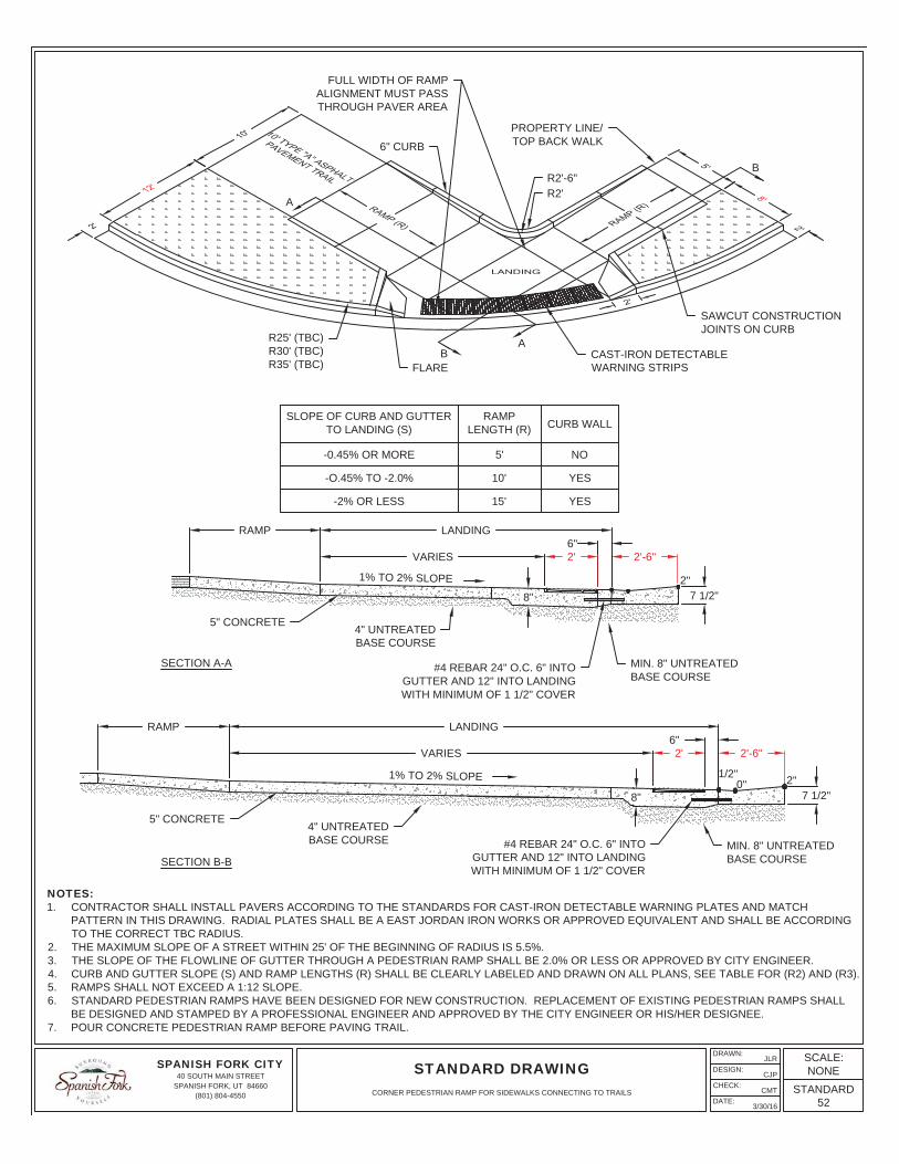
NOTES:1. CONTRACTOR SHALL INSTALL PAVERS ACCORDING TO THE STANDARDS FOR CAST-IRON DETECTABLE WARNING PLATES AND MATCH
PATTERN IN THIS DRAWING. RADIAL PLATES SHALL BE A EAST JORDAN IRON WORKS OR APPROVED EQUIVALENT AND SHALL BE ACCORDINGTO THE CORRECT TBC RADIUS.
2. THE MAXIMUM SLOPE OF A STREET WITHIN 25' OF THE BEGINNING OF RADIUS IS 5.5%.3. THE SLOPE OF THE FLOWLINE OF GUTTER THROUGH A PEDESTRIAN RAMP SHALL BE 2.0% OR LESS OR APPROVED BY CITY ENGINEER.4. CURB AND GUTTER SLOPE (S) AND RAMP LENGTHS (R) SHALL BE CLEARLY LABELED AND DRAWN ON ALL PLANS, SEE TABLE FOR (R2) AND (R3).5. RAMPS SHALL NOT EXCEED A 1:12 SLOPE.6. STANDARD PEDESTRIAN RAMPS HAVE BEEN DESIGNED FOR NEW CONSTRUCTION. REPLACEMENT OF EXISTING PEDESTRIAN RAMPS SHALL
BE DESIGNED AND STAMPED BY A PROFESSIONAL ENGINEER AND APPROVED BY THE CITY ENGINEER OR HIS/HER DESIGNEE.
4" UNTREATEDBASE COURSE
2"0"1/2"
1% TO 2% SLOPE
#4 REBAR 24" O.C. 6" INTOGUTTER AND 12" INTO LANDINGWITH MINIMUM OF 1 1/2" COVER
MIN. 8" UNTREATEDBASE COURSE
CAST-IRON DETECTABLEWARNING STRIPS
FLARE6" CURB
PROPERTY LINE/TOP BACK WALK
6" CURB
FULL WIDTH OF RAMPALIGNMENT MUST PASSTHROUGH PAVER AREA
SAWCUT CONSTRUCTIONJOINTS ON CURB
R3R2
A
A6" CURB
R1 (TBC)
SLOPE (S) SLOPE (S)
SPANISH FORK CITY40 SOUTH MAIN STREET
SPANISH FORK, UT 84660(801) 804-4550
DRAWN:
DESIGN:
CHECK:
DATE:
JLR
CJP
CMT
3/30/16
STANDARD DRAWINGSCALE:NONE
STANDARD49
PEDESTRIAN RAMP SIDEWALKS WITH PLANTERS
VARIES 2'
7 1/2"
6" 2'-6"
11"
8"5"
1"0"1/2"1% TO 2% SLOPE
#4 REBAR 24" O.C. 6" INTOGUTTER AND 12" INTO LANDINGWITH MINIMUM OF 1 1/2" COVER
MIN. 8" UNTREATEDBASE COURSESECTION A-A
NOTES:1. CONTRACTOR SHALL INSTALL PAVERS ACCORDING TO THE STANDARDS FOR CAST-IRON DETECTABLE WARNING PLATES AND MATCH
PATTERN IN THIS DRAWING. RADIAL PLATES SHALL BE A EAST JORDAN IRON WORKS OR APPROVED EQUIVALENT AND SHALL BE ACCORDINGTO THE CORRECT TBC RADIUS.
2. THE MAXIMUM SLOPE OF A STREET WITHIN 25' OF THE BEGINNING OF RADIUS IS 5.5%.3. THE SLOPE OF THE FLOWLINE OF GUTTER THROUGH A PEDESTRIAN RAMP SHALL BE 2.0% OR LESS OR APPROVED BY CITY ENGINEER.4. CURB AND GUTTER SLOPE (S) AND RAMP LENGTHS (R) SHALL BE CLEARLY LABELED AND DRAWN ON ALL PLANS, SEE TABLE FOR (R2) AND (R3).5. RAMPS SHALL NOT EXCEED A 1:12 SLOPE.6. STANDARD PEDESTRIAN RAMPS HAVE BEEN DESIGNED FOR NEW CONSTRUCTION. REPLACEMENT OF EXISTING PEDESTRIAN RAMPS SHALL
BE DESIGNED AND STAMPED BY A PROFESSIONAL ENGINEER AND APPROVED BY THE CITY ENGINEER OR HIS/HER DESIGNEE.
SPANISH FORK CITY40 SOUTH MAIN STREET
SPANISH FORK, UT 84660(801) 804-4550
DRAWN:
DESIGN:
CHECK:
DATE:
JLR
CJP
CMT
3/30/16
STANDARD DRAWINGSCALE:NONE
STANDARD50
CORNER PEDESTRIAN RAMP FOR COMBINATION SIDEWALKS CONVERTING TO SIDEWALKS WITH PLANTERS
STREET TBCRADIUS (R1) 35' 30' 25'
SIDEWALKWIDTH (W)
PROPERTY LINERADIUS (R2)
TOP BACK CURBRADIUS (R3)
PROPERTY LINERADIUS (R2)
TOP BACK CURBRADIUS (R3)
PROPERTY LINERADIUS (R2)
TOP BACK CURBRADIUS (R3)
5' 30'6" 30' 25'6" 25' 20'5" 20'
SLOPE OF CURB AND GUTTERTO LANDING (S)
RAMPLENGTH (R) CURB WALL
-0.45% OR MORE 5' NO
-O.45% TO -2.0% 10' YES
-2% OR LESS 15' YES
NOTES:1. CONTRACTOR SHALL INSTALL PAVERS ACCORDING TO THE STANDARDS FOR CAST-IRON DETECTABLE WARNING PLATES AND MATCH
PATTERN IN THIS DRAWING. RADIAL PLATES SHALL BE A EAST JORDAN IRON WORKS OR APPROVED EQUIVALENT AND SHALL BE ACCORDINGTO THE CORRECT TBC RADIUS.
2. THE MAXIMUM SLOPE OF A STREET WITHIN 25' OF THE BEGINNING OF RADIUS IS 5.5%.3. THE SLOPE OF THE FLOWLINE OF GUTTER THROUGH A PEDESTRIAN RAMP SHALL BE 2.0% OR LESS OR APPROVED BY CITY ENGINEER.4. CURB AND GUTTER SLOPE (S) AND RAMP LENGTHS (R) SHALL BE CLEARLY LABELED AND DRAWN ON ALL PLANS, SEE TABLE FOR (R2) AND (R3).5. RAMPS SHALL NOT EXCEED A 1:12 SLOPE.6. STANDARD PEDESTRIAN RAMPS HAVE BEEN DESIGNED FOR NEW CONSTRUCTION. REPLACEMENT OF EXISTING PEDESTRIAN RAMPS SHALL
BE DESIGNED AND STAMPED BY A PROFESSIONAL ENGINEER AND APPROVED BY THE CITY ENGINEER OR HIS/HER DESIGNEE.
SAWCUT CONSTRUCTIONJOINTS ON CURB
6" CURB
PROPERTY LINE/TOP BACK WALK
R3R2
CAST-IRON DETECTABLEWARNING STRIPS
A
AR1 (TBC)
SPANISH FORK CITY40 SOUTH MAIN STREET
SPANISH FORK, UT 84660(801) 804-4550
DRAWN:
DESIGN:
CHECK:
DATE:
JLR
CJP
CMT
9/24/15
STANDARD DRAWINGSCALE:NONE
STANDARD51
CORNER PEDESTRIAN RAMP COMBINATION SIDEWALKS
2'-6"2'6"
7 1/2"
LANDINGRAMP
8"
VARIES
2"0"1/2"
2'-6"6"
7 1/2"
2'VARIES
LANDINGRAMP
8"2"
SLOPE OF CURB AND GUTTERTO LANDING (S)
RAMPLENGTH (R) CURB WALL
-0.45% OR MORE 5' NO
-O.45% TO -2.0% 10' YES
-2% OR LESS 15' YES
4" UNTREATEDBASE COURSE
NOTES:1. CONTRACTOR SHALL INSTALL PAVERS ACCORDING TO THE STANDARDS FOR CAST-IRON DETECTABLE WARNING PLATES AND MATCH
PATTERN IN THIS DRAWING. RADIAL PLATES SHALL BE A EAST JORDAN IRON WORKS OR APPROVED EQUIVALENT AND SHALL BE ACCORDINGTO THE CORRECT TBC RADIUS.
2. THE MAXIMUM SLOPE OF A STREET WITHIN 25' OF THE BEGINNING OF RADIUS IS 5.5%.3. THE SLOPE OF THE FLOWLINE OF GUTTER THROUGH A PEDESTRIAN RAMP SHALL BE 2.0% OR LESS OR APPROVED BY CITY ENGINEER.4. CURB AND GUTTER SLOPE (S) AND RAMP LENGTHS (R) SHALL BE CLEARLY LABELED AND DRAWN ON ALL PLANS, SEE TABLE FOR (R2) AND (R3).5. RAMPS SHALL NOT EXCEED A 1:12 SLOPE.6. STANDARD PEDESTRIAN RAMPS HAVE BEEN DESIGNED FOR NEW CONSTRUCTION. REPLACEMENT OF EXISTING PEDESTRIAN RAMPS SHALL
BE DESIGNED AND STAMPED BY A PROFESSIONAL ENGINEER AND APPROVED BY THE CITY ENGINEER OR HIS/HER DESIGNEE.7. POUR CONCRETE PEDESTRIAN RAMP BEFORE PAVING TRAIL.
AB
B
A
FULL WIDTH OF RAMPALIGNMENT MUST PASSTHROUGH PAVER AREA
SAWCUT CONSTRUCTIONJOINTS ON CURB
6" CURB
R2'R2'-6"
PROPERTY LINE/TOP BACK WALK
CAST-IRON DETECTABLEWARNING STRIPSFLARE
R25' (TBC)R30' (TBC)R35' (TBC)
1% TO 2% SLOPE
MIN. 8" UNTREATEDBASE COURSE
#4 REBAR 24" O.C. 6" INTOGUTTER AND 12" INTO LANDINGWITH MINIMUM OF 1 1/2" COVER
MIN. 8" UNTREATEDBASE COURSE
#4 REBAR 24" O.C. 6" INTOGUTTER AND 12" INTO LANDINGWITH MINIMUM OF 1 1/2" COVER
5" CONCRETE
1% TO 2% SLOPE
4" UNTREATEDBASE COURSE
5" CONCRETE
SECTION A-A
SECTION B-B
SPANISH FORK CITY40 SOUTH MAIN STREET
SPANISH FORK, UT 84660(801) 804-4550
DRAWN:
DESIGN:
CHECK:
DATE:
JLR
CJP
CMT
3/30/16
STANDARD DRAWINGSCALE:NONE
STANDARD52
CORNER PEDESTRIAN RAMP FOR SIDEWALKS CONNECTING TO TRAILS
ELE
CTR
ICA
LC
ON
DU
IT Z
ON
E
CO
MM
UN
ICA
TIO
NS
CO
ND
UIT
ZO
NE
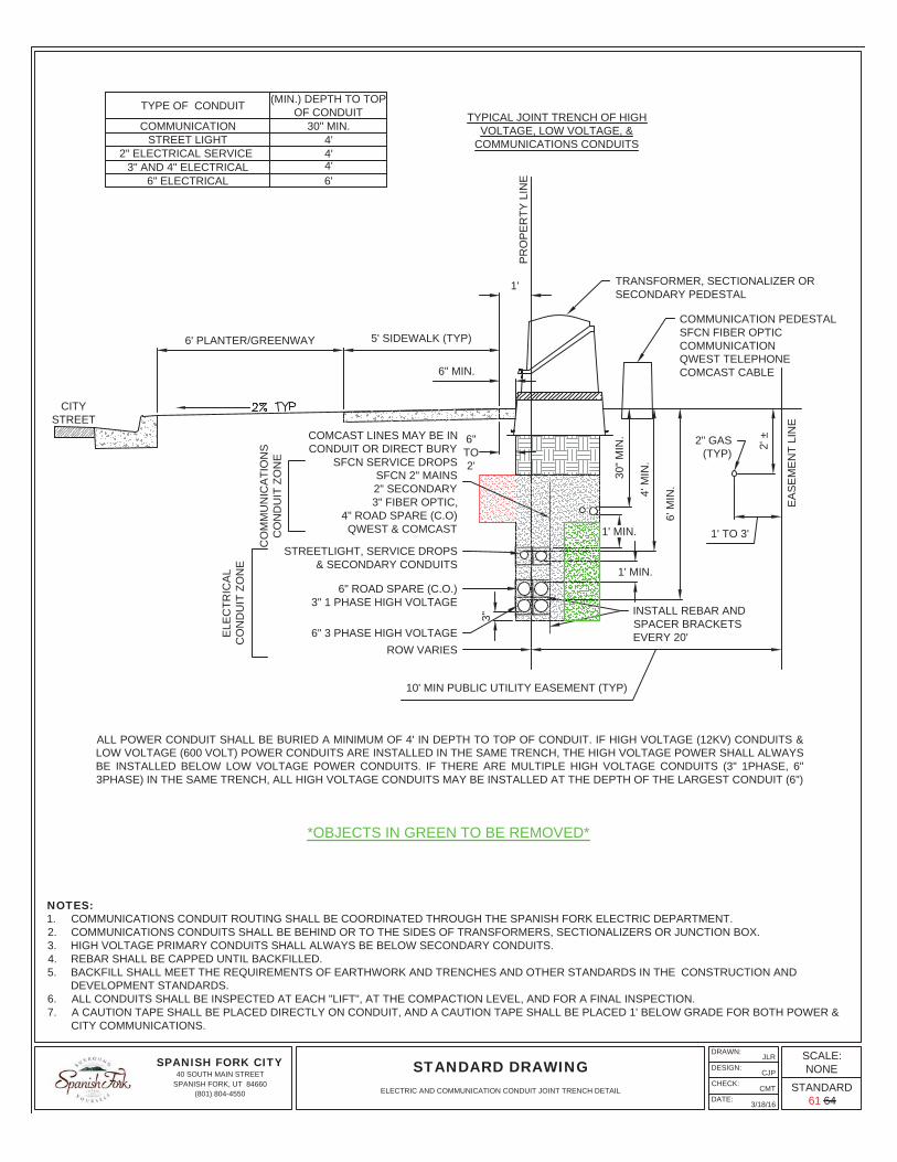
ALL POWER CONDUIT SHALL BE BURIED A MINIMUM OF 4' IN DEPTH TO TOP OF CONDUIT. IF HIGH VOLTAGE (12KV) CONDUITS &LOW VOLTAGE (600 VOLT) POWER CONDUITS ARE INSTALLED IN THE SAME TRENCH, THE HIGH VOLTAGE POWER SHALL ALWAYSBE INSTALLED BELOW LOW VOLTAGE POWER CONDUITS. IF THERE ARE MULTIPLE HIGH VOLTAGE CONDUITS (3" 1PHASE, 6"3PHASE) IN THE SAME TRENCH, ALL HIGH VOLTAGE CONDUITS MAY BE INSTALLED AT THE DEPTH OF THE LARGEST CONDUIT (6")
TYPICAL JOINT TRENCH OF HIGHVOLTAGE, LOW VOLTAGE, &
COMMUNICATIONS CONDUITS
6" ELECTRICAL3" AND 4" ELECTRICAL
2" ELECTRICAL SERVICE
TYPE OF CONDUIT
6'
4'
(MIN.) DEPTH TO TOPOF CONDUIT
COMMUNICATIONSTREET LIGHT 4'
4'
30" MIN.
NOTES:1. COMMUNICATIONS CONDUIT ROUTING SHALL BE COORDINATED THROUGH THE SPANISH FORK ELECTRIC DEPARTMENT.2. COMMUNICATIONS CONDUITS SHALL BE BEHIND OR TO THE SIDES OF TRANSFORMERS, SECTIONALIZERS OR JUNCTION BOX.3. HIGH VOLTAGE PRIMARY CONDUITS SHALL ALWAYS BE BELOW SECONDARY CONDUITS.4. REBAR SHALL BE CAPPED UNTIL BACKFILLED.5. BACKFILL SHALL MEET THE REQUIREMENTS OF EARTHWORK AND TRENCHES AND OTHER STANDARDS IN THE CONSTRUCTION AND
DEVELOPMENT STANDARDS.6. ALL CONDUITS SHALL BE INSPECTED AT EACH "LIFT", AT THE COMPACTION LEVEL, AND FOR A FINAL INSPECTION.7. A CAUTION TAPE SHALL BE PLACED DIRECTLY ON CONDUIT, AND A CAUTION TAPE SHALL BE PLACED 1' BELOW GRADE FOR BOTH POWER &
CITY COMMUNICATIONS.
CITYSTREET
6" 3 PHASE HIGH VOLTAGE
6" ROAD SPARE (C.O.)3" 1 PHASE HIGH VOLTAGE
STREETLIGHT, SERVICE DROPS & SECONDARY CONDUITS
COMCAST LINES MAY BE INCONDUIT OR DIRECT BURY
SFCN SERVICE DROPSSFCN 2" MAINS2" SECONDARY
3" FIBER OPTIC,4" ROAD SPARE (C.O)
QWEST & COMCAST
10' MIN PUBLIC UTILITY EASEMENT (TYP)
3"
ROW VARIES
INSTALL REBAR ANDSPACER BRACKETSEVERY 20'
COMMUNICATION PEDESTALSFCN FIBER OPTICCOMMUNICATIONQWEST TELEPHONECOMCAST CABLE
TRANSFORMER, SECTIONALIZER ORSECONDARY PEDESTAL
PR
OP
ER
TY L
INE
1'
EA
SE
ME
NT
LIN
E
6' PLANTER/GREENWAY 5' SIDEWALK (TYP)
6" MIN.
6"TO2'
30" M
IN.
4' M
IN.
6' M
IN.
1' MIN.
1' MIN.
1' TO 3'
2' ±2" GAS
(TYP)
SPANISH FORK CITY40 SOUTH MAIN STREET
SPANISH FORK, UT 84660(801) 804-4550
DRAWN:
DESIGN:
CHECK:
DATE:
JLR
CJP
CMT
3/18/16
STANDARD DRAWINGSCALE:NONE
STANDARD61 64
ELECTRIC AND COMMUNICATION CONDUIT JOINT TRENCH DETAIL
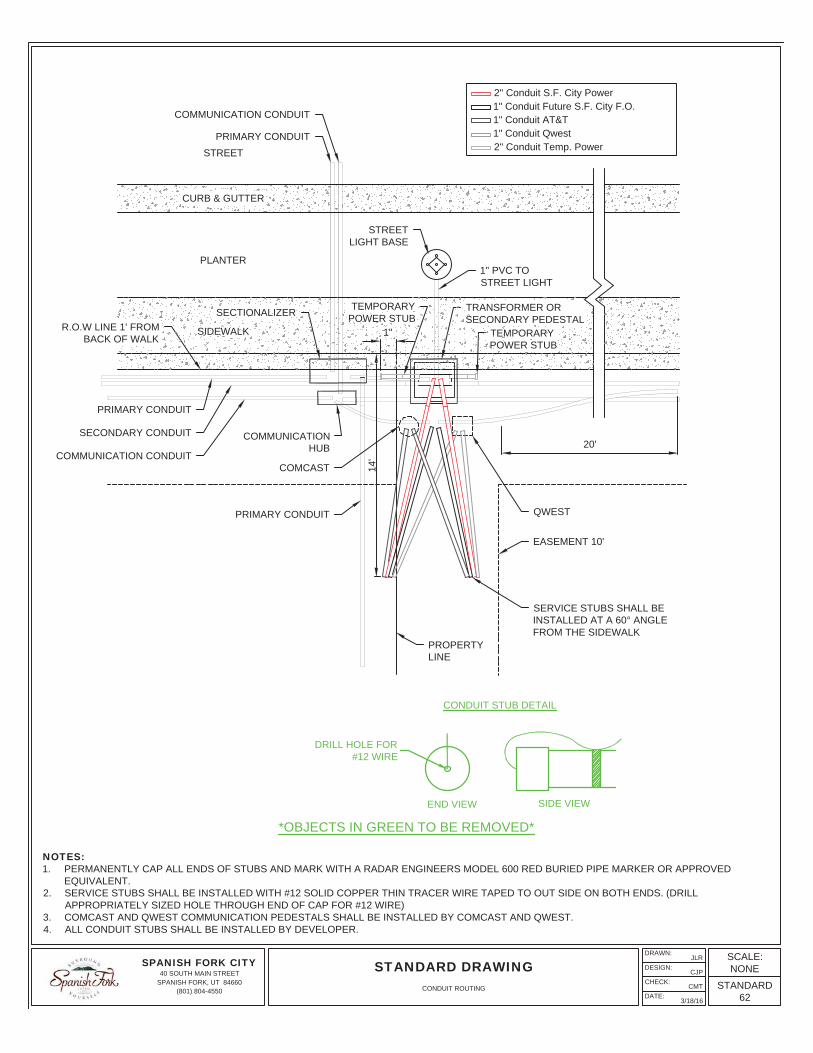
*OBJECTS IN GREEN TO BE REMOVED*
2" Conduit S.F. City Power1" Conduit Future S.F. City F.O.1" Conduit AT&T1" Conduit Qwest2" Conduit Temp. Power
NOTES:1. PERMANENTLY CAP ALL ENDS OF STUBS AND MARK WITH A RADAR ENGINEERS MODEL 600 RED BURIED PIPE MARKER OR APPROVED
EQUIVALENT.2. SERVICE STUBS SHALL BE INSTALLED WITH #12 SOLID COPPER THIN TRACER WIRE TAPED TO OUT SIDE ON BOTH ENDS. (DRILL
APPROPRIATELY SIZED HOLE THROUGH END OF CAP FOR #12 WIRE)3. COMCAST AND QWEST COMMUNICATION PEDESTALS SHALL BE INSTALLED BY COMCAST AND QWEST.4. ALL CONDUIT STUBS SHALL BE INSTALLED BY DEVELOPER.
SIDEWALK
PRIMARY CONDUIT
COMCAST
COMMUNICATIONHUB
PRIMARY CONDUIT
SECONDARY CONDUIT
COMMUNICATION CONDUIT
14'
R.O.W LINE 1' FROMBACK OF WALK
SECTIONALIZER
PRIMARY CONDUIT
COMMUNICATION CONDUIT
PLANTER
CURB & GUTTER
STREET
STREETLIGHT BASE
1" PVC TOSTREET LIGHT
TRANSFORMER ORSECONDARY PEDESTAL
TEMPORARYPOWER STUB
TEMPORARYPOWER STUB
1"
20'
QWEST
EASEMENT 10'
SERVICE STUBS SHALL BEINSTALLED AT A 60° ANGLEFROM THE SIDEWALK
PROPERTYLINE
DRILL HOLE FOR#12 WIRE
END VIEW SIDE VIEW
CONDUIT STUB DETAIL
SPANISH FORK CITY40 SOUTH MAIN STREET
SPANISH FORK, UT 84660(801) 804-4550
DRAWN:
DESIGN:
CHECK:
DATE:
JLR
CJP
CMT
3/18/16
STANDARD DRAWINGSCALE:NONE
STANDARD62
CONDUIT ROUTING
*OBJECTS IN GREEN TO BE REMOVED*
GRADE
SECONDARY JUNCTIONPEDESTAL (TYP)
SFCN PEDESTAL
6"
2" TO 4"(TYP)
NOTES:1. CONDUITS ENTERING ANY JUNCTION BOX SHALL HAVE END BELLS TO PROTECT WIRE FROM DAMAGE.2. SECONDARY WIRE SHALL BE RATED FOR 600 VOLTS AND BE THE URD TYPE. CARE SHALL BE TAKEN IN INSTALLATION AS NOT TO DAMAGE
WIRE INSULATION.3. ALL SECONDARY WIRE SHALL EXTEND A MINIMUM OF 36" & A MAXIMUM OF 48" FROM TOP OF BOX (WITHOUT THE LID).4. SECONDARY PEDESTALS SHALL FACE TOWARDS THE STREET AND SHALL BE LEVEL.5. ROADBASE SHALL BE USED UNDER ALL PEDESTALS. ROADBASE SHALL BE COMPACTED TO 95% OF DRY DENSITY. COMPACTION TESTS SHALL
BE TAKEN PRIOR TO ANY PEDESTALS BEING SET INTO PLACE.6. CONDUITS SHALL BE 2" TO 4" HIGHER THAN INSIDE GRADE OF PEDESTAL. (INSIDE GRADE IS THE BOTTOM OF THE PEDESTAL)7. LOCKING MECHANISM SHALL BE 10" FROM FINISHED GRADE.8. USE ONLY APPROVED JUNCTION PEDESTALS: PENCELL AG20HDXCL-NL & NORDIC PSP-15-15-30-MG OR APPROVED EQUIVALENT.9. SECONDARY SERVICE LATERAL CONDUITS SHALL BE SEPARATED HORIZONTALLY IN THE TRENCH FROM COMMUNICATIONS CONDUITS.
SIDEWALK
SIDEWALK
3" PVC SECONDARYCONDUIT WITH 4/0URD WIRE IS TYPICAL
CONCRETE PAD DETAIL
LEAVE 36" OF WIRE INJUNCTION BOX (TYP)
END BELLS ONALL CONDUITS
SIDEWALK
4" CONCRETE ON 4" COMPACTEDUBC AROUND J-BOX TO BEFLUSH WITH SIDEWALK
PROPERTY LINE
SFCN PEDESTAL SUPPLIEDAND DESIGNED BY CITY
SFCN COMMUNICATIONS CONDUITS
1" SFCN SERVICELATERAL CONDUIT STUBS
2" OR 212" ELECTRIC SERVICE
LATERAL CONDUIT STUBS (TYP)
TOP VIEW
RIGHT SIDE VIEW
18"
15"
15"
12"
6"
12"
12"
SECONDARY JUNCTIONPEDESTAL (TYP)
12"
SPANISH FORK CITY40 SOUTH MAIN STREET
SPANISH FORK, UT 84660(801) 804-4550
DRAWN:
DESIGN:
CHECK:
DATE:
JLR
CJP
CMT
3/16/16
STANDARD DRAWINGSCALE:NONE
STANDARD64 72
SECONDARY JUNCTION PEDESTAL
NOTES:1. 14 GUAGE SOLID THIN COPPER WIRE SHALL BE INSTALLED THE ENTIRE LENGTH OF EACH STUBBED CONDUIT.2. CONDUIT COMING INTO ANY TRANSFORMER MUST HAVE A PVC COUPLING, ADAPTER, OR AN INSULATING BUSHING.3. GROUND SLEEVE FOR 167.5 KVA TRANSFORMER OR LESS SHALL BE NORDIC CBP-37-43-15AB-2 OR APPROVED EQUIVALENT.4. GROUND LEVEL INSIDE THE GROUND SLEEVE IS THE BOTTOM OF THE GROUND SLEEVE.5. ALL SECONDARY CABLE TO BE URD SELF-HEALING TYPE.6. PULL ROPE MUST BE SECURELY TIED TO THE GROUND SLEEVE OR CONDUIT.
GRADE
SECONDARYCONDUIT
PRIMARY CONDUIT
2" PVC COMMUNICATIONDUCTS
36" RIGIDMETAL SWEEP
SECONDARY BUSHINGS(LOW VOLTAGE)
PULL ROPE
ATTACH #6 SOLID COPPER GROUNDWIRE TO GROUND WITH AN APPROVED
GROUNDING CONNECTOR
PRIMARY BUSHINGS(HIGH VOLTAGE)
SINGLE PHASEPAD MOUNT
TRANSFORMER
SIDEWALK
PROPERTY LINE
TOP VIEW
FRONT VIEW
RIGHT SIDE VIEW
PRIMARY AND SECONDARYCONDUITS MUST BE IN THEFRONT 11.9" OF THE GROUNDSLEEVE WINDOW
TRANSFORMERRIGHT SIDE VIEW
EXTEND WIRE 3' INTOCOMMUNICATION BOX
COMMUNICATIONPEDESTAL ASDESIGNED BYTHE CITY
9" X 20"PEDESTAL
5/8" X 8' COPPER CLADGROUND ROD (TYP)
10"
43" 11.9"
22"
37"
712"
6"
2" TO 4" (TYP)4" TO 6"
(TYP)
4" CONCRETE ON 4" COMPACTEDUBC AROUND TRANSFORMER PAD
TO BE FLUSH WITH SIDEWALK
CONCRETE PAD DETAIL
PROPERTYLINE
12" 12"
12"
6"
SIDEWALK
12"
TEMPORARY STUB
TEMPORARY STUB
TEMPORARYSTUB
SPANISH FORK CITY40 SOUTH MAIN STREET
SPANISH FORK, UT 84660(801) 804-4550
DRAWN:
DESIGN:
CHECK:
DATE:
JLR
CJP
CMT
3/17/16
STANDARD DRAWINGSCALE:NONE
STANDARD65 70
SINGLE PHASE PAD MOUNT TRANSFORMER
*OBJECTS IN GREEN TO BE REMOVED*
3" RMC OR F.G.90° ELBOWS (TYP)
SIDEWALK
SFCNCOMMUNICATIONSPEDESTAL ASDESIGNED &PROVIDED BY THECITY
4-POINT MOUNTINGJUNCTION (TYP)
STAINLESS STEELCAM ARM
FINISHED GRADEFINISHED GRADE
2' 1/2"
2' 3
/4"
2' 1
/2"
10" (
TYP
)
35"
41 1/2"
31 7/8"
52 3
/4"
46"
2" T
O 4
"
1' MIN./3" MAX.
2" T
O 4
"
6" (MIN.)
NOTES:1. SECTIONALIZER CABINET UNITS FOR 200 AMP 1 PHASE ARE TO BE FABRICATED FROM FIBERGLASS COMPOSITE & MEET SPANISH FORK
ELECTRIC'S SPECIFICATIONS. CONDUIT OPENINGS MUST BE WITHIN THE GROUND SLEEVE WINDOW OF THE SECTIONALIZER.2. BLOW IN 1350 LB. MULE TAPE IN ALL CONDUITS AND TIE SECURELY TO 4 POINT MOUNTING PLATE.3. 200 AMP 1 PHASE SECTIONALIZER P/N: NORDIC ND-150-MG-101-X-X OR AN APPROVED EQUIVALENT.4. CONTRACTOR TO FURNISH & INSTALL 200-AMP 4-POINT MOUNTING JUNCTION PLATES & 4 POINT JUNCTIONS.5. RIGID METAL (RMC) OR FIBERGLASS (F.G.) SHALL BE USED FOR ALL ELBOWS, OR BENDS 45 DEGREES OR GREATER.6. SFCN COMMUNICATIONS ELBOWS SHALL BE LONG SWEEP (36") RMC OR F.G..7. SECTIONALIZER SHALL BE SET A MINIMUM OF 6" BEHIND SIDEWALK8. CONCRETE SHALL BE POURED IN FRONT OF THE SECTIONALIZER IN BETWEEN THE SECTIONALIZER & SIDEWALK.9. AREA AROUND SECTIONALIZER SHALL BE BACKFILLED AND LEVELED A MINIMUM OF 12' IN ALL DIRECTIONS AROUND THE SECTIONALIZER TO
PROVIDE A SAFE WORKING AREA FOR THE ELECTRIC DEPARTMENT.
58"X8' COPPER-CLADGROUND ROD (TYP)
3" PRIMARYCONDUIT (TYP)
END BELLS ON ALLCONDUITS (TYP)
LOCKING MECHANISM
SIDEWALK
4" CONCRETE ON 4" COMPACTEDUBC AROUND SECTIONALIZER TOBE FLUSH WITH SIDEWALK (TYP)
6"
12"
SECTIONALIZER
12"
12"
CONCRETE PAD DETAIL
SPANISH FORK CITY40 SOUTH MAIN STREET
SPANISH FORK, UT 84660(801) 804-4550
DRAWN:
DESIGN:
CHECK:
DATE:
JLR
CJP
CMT
3/16/16
STANDARD DRAWINGSCALE:NONE
STANDARD66 65
200-AMP 1 PHASE SECTIONALIZER
NOTES:1. SECTIONALIZER CABINET UNITS FOR 100 AMP 1 PHASE AND 3 PHASE ARE TO BE FABRICATED FROM FIBERGLASS COMPOSITE. CONDUIT
OPENINGS MUST BE WITHIN THE GROUND SLEEVE WINDOW OF THE SECTIONALIZER. USE MANUFACTURER'S APPROVED GROUND SLEEVE FOREACH SECTIONALIZER.
2. BLOW IN 1350 LB MULE TAPE IN ALL CONDUITS AND TIE SECURELY TO 4 POINT MOUNTING PLATE.3. CONTRACTOR TO FURNISH & INSTALL 200-AMP 4-POINT MOUNTING JUNCTION AND PLATES & 4-POINT JUNCTIONS.4. 200 AMP 1 PHASE SECTIONALIZER P/N: NORDIC ND-150-MG-101-X-X OR WESTERN POWER PRODUCTS P/N: SPM-320-47-MG-DF35. 200 AMP 3 PHASE SECTIONALIZER P/N: NORDIC ND-350-MG-101-X-X OR WESTERN POWER PRODUCTS P/N: SPM-540-47-MG-DF3
1 PHASEFRONT VIEW
5/8" X 8' COPPER CLADGROUND ROD (TYP)
ATTACH #6 SOLIDCOPPER GROUND WIRE
TO GROUND WITH ANAPPROVED GROUNDING
CONNECTOR
SIDEWALK
CURB & GUTTERGRADE
GRADE
3" CONDUIT (TYP)
5/8" X 8' COPPER CLADGROUND ROD (TYP)
PVC COMMUNICATIONCONDUIT (TYP)
36" RADIUS RIGIDMETAL SWEEP
EXTEND WIRE 3' INTOCOMMUNICATION BOX
SFCN COMMUNICATIONPEDESTAL AS DESIGNEDBY THE CITY
5/8" X 8' COPPER CLADGROUND ROD (TYP)
5" CONDUIT (TYP)
PVC PIPE ORINSULATINGBUSHINGS (TYP)
END BELLS ONALL CONDUITS
PARKING STAND
STAINLESSSTEEL CAM ARM
STAINLESS STEELPROP ARM
P-107
ZINC COATEDEYEBOLT
3 PHASEFRONT VIEW
46"
2" T
O 4
"
3' MAX1' MIN
31"
523
8"
7512"
4" TO 6"(TYP)
5112"
47"
1" 15"
213
4"25
1 2"2" TO 4"
(TYP)
2' 1/2"
SIDEWALK
4" CONCRETE ON4" COMPACTED
UBC AROUNDSECTIONALIZER TO
BE FLUSH WITHSIDEWALK (TYP)
12"
6"
12" 12"
SECTIONALIZER
CONCRETE PAD DETAIL
SPANISH FORK CITY40 SOUTH MAIN STREET
SPANISH FORK, UT 84660(801) 804-4550
DRAWN:
DESIGN:
CHECK:
DATE:
JLR
CJP
CMT
3/16/16
STANDARD DRAWINGSCALE:NONE
STANDARD67 66
200-AMP 1 AND 3 PHASE FIBERGLASS SECTIONALIZER
NOTES:1. SECTIONALIZER CABINET UNITS FOR 600 AMP 3 PHASE ARE TO BE FABRICATED FROM FIBERGLASS COMPOSITE & MEET SPANISH FORK
ELECTRIC'S SPECIFICATIONS. CONDUIT OPENINGS MUST BE WITHIN THE GROUND SLEEVE WINDOW OF THE SECTIONALIZER.2. BLOW IN 1/4" POLY ROPE AND TIE SECURELY TO 4 POINT MOUNTING PLATE.3. GROUND SLEEVE AND CAP SHALL HAVE #4 REBAR 12" ON CENTER IN ALL DIRECTIONS. USE PRE-CAST CEMENT GROUND SLEEVE AND CAP
WITH DIMENTIONS AS SHOWN ABOVE.4. CONTRACTOR TO FURNISH & INSTALL 600-AMP 4-POINT MOUNTING JUNCTION AND PLATES & 4-POINT JUNCTION
GRADE
5/8" x 8' COPPER CLADGROUND ROD (TYP) 94.45"
30"
SFCN COMMUNICATIONPEDESTAL AS DESIGNEDBY THE CITY
EXTEND WIRE 3' INTOCOMMUNICATION BOX
53"
GROUND LEVEL INSIDESLEEVE (TYP)
5/8" x 8' COPPER CLADGROUND ROD (TYP)
ATTACH #6 SOLID COPPERGROUND WIRE TO GROUNDWITH AN APPROVEDGROUNDING CONNECTOR
SIDEWALK
CURB & GUTTER
6" CONDUIT (TYP)
PVC COMMUNICATIONCONDUIT (TYP)
36" RADIUS RIGID METALOR FIBERGLASS SWEEPS
PVC PIPE OR INSULATINGBUSHINGS (TYP)
END BELLS ON ALL CONDUIT
GOUND SLEEVE (TYP)
NORDIC ND-383054-MG-PA71-X-XSST LOCK
6812"
29"
241 2" 53
1 2"
18"
2" T
O 4
"(T
YP
)
4" T
O 6
"(T
YP
)2' MAX1' MIN
2"TO
4"
2" T
O 4
"(T
YP
)
GRADE 10"
SIDEWALK
4" CONCRETE ON 4" COMPACTEDUBC AROUND SECTIONALIZER TOBE FLUSH WITH SIDEWALK (TYP)
12"
6"
12" 12"
SECTIONALIZER
CONCRETE PAD DETAIL
SPANISH FORK CITY40 SOUTH MAIN STREET
SPANISH FORK, UT 84660(801) 804-4550
DRAWN:
DESIGN:
CHECK:
DATE:
JLR
CJP
CMT
3/16/16
STANDARD DRAWINGSCALE:NONE
STANDARD68 69
600-AMP 3 PHASE FIBERGLASS SECTIONALIZER
NOTES:1. SWITCH GEAR GROUND SLEEVE SHALL BE PROVIDED BY SPANISH FORK ELECTRIC AND
INSTALLED BY ELECTRICAL CONTRACTOR AS PER CITY SUPPLIED LAYOUT2. 1/4" POLY ROPE SHALL BE BLOWN INTO CONDUIT AND TIED SECURELY TO GROUND ROD3. CONDUIT LAYOUT DETAIL SHALL BE GIVEN BY SPANISH FORK ELECTRIC DURING PRE
CONSTRUCTION MEETING4. TYPICAL FOR SITE DEVELOPMENTS
2" T
O 4
"(T
YP
)
76"
93.5"
2" T
O 4
"(T
YP
)
26"
92"
4" T
O 6
"(T
YP
)
FG/TBC
10"
36"
61"
70"
65.5"
74"
74"
61"
76"
65.5"
6"
(TY
P)
6"(TYP)
2' CONCRETE SKIRT COMPLETELYAROUND GROUND SLEEVE
6" CONDUIT (TYP)
60" FIBERGLASSLONG SWEEPS
SCH 40 ELECTRICALGRADE PVC PIPE
END BELLS ON ALL CONDUIT
GROUND SLEEVE (TYP)
5/8" X 8' COPPER CLADGROUND ROD (TYP)
CURB AND GUTER
5/8" X 8' COPPER CLADGROUND ROD (TYP)
GROUND LEVEL INSIDESLEEVE (TYP)
4"
2'
2'
5/8" X 8' COPPER CLADGROUND ROD (TYP)
SIDEWALK
SPANISH FORK CITY40 SOUTH MAIN STREET
SPANISH FORK, UT 84660(801) 804-4550
DRAWN:
DESIGN:
CHECK:
DATE:
TC
TC
KP
3/16/16
STANDARD DRAWINGSCALE:NONE
STANDARD69 68
600 AMP PSE 9/11 SWITCHGEAR
2" T
O 4
"(T
YP
)
48"
62.5"
2" T
O 4
"(T
YP
)
26"
83"
4" T
O 6
"(T
YP
)
FG/TBC
10"
36"
24"
55"
70"
68.5"
36"
68.5
"
55"
48"
36"
24"
18"
4"
2' CONCRETE SKIRT COMPLETELYAROUND GROUND SLEEVE
5/8" X 8' COPPER CLADGROUND ROD (TYP)
5/8" X 8' COPPER CLADGROUND ROD (TYP)
6" CONDUIT (TYP)
60" FIBERGLASSLONG SWEEPS
SCH 40 ELECTRICALGRADE PVC PIPE
END BELLS ON ALL CONDUIT
GROUND SLEEVE (TYP)
GROUND LEVEL INSIDESLEEVE (TYP)
NOTES:1. SWITCH GEAR GROUND SLEEVE SHALL BE PROVIDED BY SPANISH FORK ELECTRIC AND
INSTALLED BY ELECTRICAL CONTRACTOR AS PER CITY SUPPLIED LAYOUT2. 1/4" POLY ROPE SHALL BE BLOWN INTO CONDUIT AND TIED SECURELY TO GROUND ROD3. CONDUIT LAYOUT DETAIL SHALL BE GIVEN BY SPANISH FORK ELECTRIC DURING PRE
CONSTRUCTION MEETING4. TYPICAL FOR COMMERCIAL TRANSFORMER PROTECTION FOR 750KVA AND LARGER
CURB AND GUTTER
2'
2'
SIDEWALK
5/8" X 8' COPPER CLADGROUND ROD (TYP)
SPANISH FORK CITY40 SOUTH MAIN STREET
SPANISH FORK, UT 84660(801) 804-4550
DRAWN:
DESIGN:
CHECK:
DATE:
TC
TC
KP
3/16/16
STANDARD DRAWINGSCALE:NONE
STANDARD70 67
600 AMP PSE 3/5 SWITCHGEAR
1 2 3 4 5 6
NOTES:1. INSTALL AN IN-LINE 10 AMP FUSE & FUSE HOLDER ON THE UNGROUNDED 120/240V STREET LIGHT CONDUCTOR(S) IN JUNCTION BOX.2. CONDUIT ENTERING INTO ANY SECONDARY PEDESTAL MUST HAVE A FABRICATED BELL END.3. SECONDARY PEDESTAL SHALL BE NORDIC PSP-15-15-30-MG OR PENCELL AG20HDXCL-NL APPROVED EQUIVALENT.4. GROUND LEVEL INSIDE THE GROUND SLEEVE IS THE BOTTOM OF THE GROUND SLEEVE.5. ALL SECONDARY CABLE SHALL EXTEND A MINIMUM OF 36" & A MAXIMUM OF 48" FROM TOP OF SECONDARY BOX (WITHOUT LID) AND SHALL BE
THE URD TYPE CABLE.6. ROAD BASE SHALL BE USED UNDER SECONDARY BOXES. ROAD BASE SHALL BE COMPACTED TO 95% AND BE TESTED PRIOR TO BOX BEING
SET INTO PLACE.7. ALL SERVICE STUBS SHALL EXTEND 1' PAST PROPERTY LINE.8. SECONDARY WATERTIGHT, INSULATED SET SCREW CONNECTORS (UTILCO PED-6-350-SSP, ELASTIMOLD USB63S, RAYCHEM GPRT-350-6P-C(B6)
OR EQUIVALENT) SHALL ACCEPT A MINIMUM OF SIX INDIVIDUAL WIRES, UNLESS OTHERWISE APPROVED BY ELECTRICAL DEPARTMENT.
WATERTIGHT, INSULATED600V SET SCREW CONNECTOR (TYP)(SIDE VIEW)
3" SECONDARY CONDUIT (TYP)
FACTORY FABRICATEDEND BELLS ON CONDUITS
SECONDARY WATERTIGHT INSULATEDCONNECTOR TYPE BUSSBAR(MINIMUM 6 POSITION)
SECONDARY PEDESTALSFCN COMMUNICATIONPEDESTAL PROVIDED &DESIGNED BY THE CITY
COMMUNICATION CONDUIT(S)
GRADE 10"
36" (
MIN
)48
" (M
AX
)W
IRE
(TY
P)
SPANISH FORK CITY40 SOUTH MAIN STREET
SPANISH FORK, UT 84660(801) 804-4550
DRAWN:
DESIGN:
CHECK:
DATE:
JLR
CJP
CMT
4/20/16
STANDARD DRAWINGSCALE:NONE
STANDARD72 73
SECONDARY PEDESTAL, WIRE & CONNECTIONS
11"
8"
11" D
IA. O
PE
NIN
G
BOLT THREADSTO EXTRUDE FROMCONCRETE 4"-6"
NUT & WASHER
#8-2 STR. THWNFROM SOURCE #6 CU STR. BONDING
CONDUCTOR FROM "UFER"REBAR TO STREET LIGHT BASE
1" PVC & 1" RIGID METAL90° ELBOW IN CONCRETE
24" DIA. CONCRETE BASE
20" DIA. STREET LIGHT BASE
15" DIA. BOLT CIRCLE
DOOR OPENING
CURB
GUTTER
ORIENTATION VIEWED FROM TOP OF POLE
RUBBED FINISH
STREET LIGHT BASE DETAIL
4-#4 REBAR UPRIGHTS& 4-#4 REBAR RINGS
10"
6'
2'
SEE NOTE 9
NOTES:1. STREET LIGHT BASES SHALL BE INSPECTED PRIOR TO POURING CONCRETE.2. STREET LIGHT BASES SHALL BE 2' IN DIAMETER AND 6' IN DEPTH WITH 10" OF BASE EXPOSED ABOVE TOP BACK OF CURB.3. EXPOSED CONCRETE SHALL HAVE A RUBBED FINISH, WITH ALL HONEYCOMB OR CRACKS FILLED.4. STREET LIGHT BASE SHALL BE CENTERED IN PLANTER STRIP OR 3' FROM TOP BACK OF CURB TO CENTER OF BASE IF NO PLANTER STRIP IS
PRESENT.5. SONNETUBE SHALL BE KEPT DRY AND SHALL NOT BE ALLOWED TO DEFORM IN ANY WAY.6. CONCRETE COVER OVER REINFORCING STEEL SHALL BE 2" UNLESS OTHERWISE APPROVED.7. USE 4-#4 REBAR UPRIGHTS & 4-#4 REBAR RINGS SPACED EVENLY AND KEPT 2" FROM SIDES, TOP AND BOTTOM OF CONCRETE.8. GROUT GAP INBETWEEN STREET LIGHT AND BASE & PROVIDE 12" DRAIN PIPE FOR WATER.9. ALL STREET LIGHT BASES ALONG STATE ROADS ARE TO BE FLUSH WITH THE TBC AND CONNECTED TO THE LIGHT POLE WITH A BREAKAWAY
SUPPORT.
SPANISH FORK CITY40 SOUTH MAIN STREET
SPANISH FORK, UT 84660(801) 804-4550
DRAWN:
DESIGN:
CHECK:
DATE:
JLR
CJP
CMT
3/16/16
STANDARD DRAWINGSCALE:NONE
STANDARD73 76
STREET LIGHT POLE BASE DETAIL
#12-2 W/GROUND CU. THWNTO STREET LIGHT LUMINAIRE
#8-2 W/GROUND THWN FROM SOURCE
GROUT & INSTALL DRAIN AT GAPS
BASES SHALL BE TROWELEDAND RUBBED TO SMOOTH TEXTURE
STREET LIGHT BASECENTERED IN PLANTER (TYP)
SIDEWALK PLANTER STRIP
CU
RB
& G
UTTE
R
STREET LIGHT FUSING
DECORATIVE STREET LIGHT POLE & LIGHT FIXTURE POLE BASE LAYOUT PLAN VIEW
MODERN CAGEWITH BLACK FINISH
CLEAR LENSCLB DOORWITH BLACK FINISH
BLACK FINISH
MODERN FINIALWITH BLACK FINISH
4"
20'
2'-1
1"
10"
3" O.D.TENON
2"1'8"
6'
4' D
EP
TH
COPPERTOP ACCESS
FINISHED GRADE
SEE NOTE 8
NOTES:1. STREET LIGHT CONDUCTOR(S) SHALL HAVE AN INLINE 10 AMP FUSE & SET SCREW TYPE FUSEHOLDER INSTALLED IN JUNCTION BOX OR
TRANSFORMER.2. 1" PVC CONDUIT WITH RIGID STEEL OR FIBERGLASS ELBOWS TO RUN FROM BASE OF STREET LIGHT TO CLOSEST TRANSFORMER OR
SECONDARY PEDESTAL.3. IF PLANTER EXISTS STREET LIGHT SHALL BE CENTERED IN PLANTER STRIP. IF THERE IS NO PLANTER LIGHT BASE SHALL BE 3' ON CENTER
FROM TOP BACK OF CURB. BOLT PATTERN SHALL BE ON A DIAMOND TO THE CURB UNLESS OTHERWISE SPECIFIED.4. STREET LIGHT POLE, FIXTURE, LUMINAIRE, PHOTOCELL, BOLTS, NUTS, WASHERS SHALL BE PROVIDED BY CITY.5. BASES SHALL HAVE A SMOOTH OR RUBBED FINISH, FREE FROM HONEYCOMB & CRACKS.6. STREET LIGHT BASE SHALL BE BONDED TO STREET LIGHT POLE BY A "UFER" TYPE #6 CU BONDING CONDUCTOR.7. THE GROUNDING CONDUCTOR SHALL BE TERMINATED WITH THE GROUNDED (NEUTRAL) CONDUCTOR AT THE SOURCE.8. ALL STREET LIGHT BASES ALONG STATE ROADS ARE TO BE FLUSH WITH THE TBC AND CONNECTED TO THE LIGHT POLE WITH A BREAKAWAY
SUPPORT.
WIRE FUSE HOLDER WIRESTRIPPER WIRE
FUSE HOLDER
RUBBER BOOTSET SCREW
10 AMP FUSE (TYP)
120 VOLT CIRCUITWITH GROUND (TYP)
SPANISH FORK CITY40 SOUTH MAIN STREET
SPANISH FORK, UT 84660(801) 804-4550
DRAWN:
DESIGN:
CHECK:
DATE:
JLR
CJP
CMT
3/16/16
STANDARD DRAWINGSCALE:NONE
STANDARD74
DECORATIVE STREET LIGHT POLE AND FIXTURE
5'-6
"
SURFACE MOUNT FRONT VIEW
4' (T
YP
)
1' MIN.
6' (MAX.)
SERVICE SIZE NEC WIRE SIZE CONDUIT SIZE100 AMP #2 ALU 2"125 AMP 1/0 ALU 2"150 AMP 2/0 ALU 2"200 AMP 4/0 ALU 3" 2"201 AMPS-400 AMPS SEE ELECTRICAL DIVISION
METERBASE (TYP)
12" PVC OR EMT TO
PROTECT GROUND WIRE
GROUND TO 5 8"X8' GROUND ROD& "UFER" GROUND (TYP)
CORROSION TAPE ONRIGID METAL CONDUIT
45>90 DEGREE (TYP)
POWER STUBAT 4' DEPTH
(TYP)
BOLT ON HUB ONLY (TYP)
PERMANENT PVCTYPE END CAPS
TRANSFORMEROR JUNCTION BOX
COMMUNICATIONSPEDESTALS (TYP)
1" COMMUNICATIONSSERVICE CONDUIT STUBS
UNISTRUT SHALL BESECURELY FASTENED TO
CONCRETE FOUNDATION WITHSUITABLE CONCRETE ANCHORS
AND BE A MIN. OF 3' IN LENGTH
CONDUITS SECURELYATTACHED TO UNISTRUT
WITH UNISTRUT TYPECLAMPS
RIGID
6" SPACING (TYP.)
NOTES:1. ALL MATERIALS TO BE SUPPLIED BY CUSTOMER EXCEPT METER.2. ALL TEMPORARY/PERMANANT EQUIPMENT SHALL COMPLY WITH CURRENT N.E.C., N.E.S.C, AND CITY STANDARDS.3. SPANISH FORK ELECTRICAL DIVISION WILL FURNISH AND INSTALL METER AND CONNECT SERVICE IN TRANSFORMER OR JUNCTION BOX.4. SERVICE CONDUCTORS SHALL MEET CURRENT NATIONAL ELECTRIC CODE.5. GROUND ROD TO BE DRIVEN A MINIMUM OF 6' IN UNDISTURBED SOIL. GROUNDING CONDUCTOR CONNECTED TO GROUND ROD SHALL BE
MINIMUM OF #6 COPPER.6. UNISTRUT TO BE OF ONE PIECE AND OF 2' IN LENGTH7. ENOUGH WIRE SHALL BE PROVIDED TO EXTEND A MINIMUM OF 3' PAST THE TRANSFORMER OR SECONDARY PEDESTAL GROUND SLEEVE.8. RIGID METAL CONDUITS SHALL BE TAPED WITH ANTI-CORROSION TAPE. TAPE SHALL EXTEND 6" ABOVE FINISHED GRADE.9. ALL POWER SERVICE LATERAL CONDUITS SHALL BE 2" OR 3". TO DETERMINE SIZE FIELD VERIFY BY EXCAVATING THE SERVICE STUBS.10. METERBASE SHALL BE LOCATED WITHIN THE FRONT 6' OF THE SIDE OF THE HOUSE. OTHER LOCATION SHALL FIRST BE APPROVED BY POWER
DEPT.11. METER SOCKET SHALL BE PLACED A MINIMUM OF 4'6" AND A MAXIMUM OF 6' TO CENTER OF SOCKET FROM FINISHED GRADE.12. CONTACT POWER DEPT. TO SCHEDULE APPOINTMENT FOR ASSISTANCE IN PULLING IN URD WIRE INTO ENERGIZED TRANSFORMERS.13. MAIN DISCONNECT BREAKER TO BE INSTALLED AT TIME OF INSPECTION.
FINISHED GRADE
SERVICE LATERAL CONDUIT2"-100 TO 150 AMP3"-200 AMP ELECTRIC
SPANISH FORK CITY40 SOUTH MAIN STREET
SPANISH FORK, UT 84660(801) 804-4550
DRAWN:
DESIGN:
CHECK:
DATE:
JLR
CJP
CMT
3/16/16
STANDARD DRAWINGSCALE:NONE
STANDARD75 77
RESIDENTIAL UNDERGROUND SERVICE 200 AMPS OR LESS
3' (MIN.)
12" EMT OR PVC TO PROTECT
GROUNDING CONDUCTOR SHALL BESECURELY FASTENED TO BUILDING
#6 COPPERGROUNDING CONDUCTOR
(2) 5 8"X8' COPPER-CLADGROUND RODS (TYP)
ROOF FLASHING
WEATHERHEAD
CONDUCTOR LENGTH SHALL BE AMINIMUM OF 24" OUT OF WEATHERHEAD
POINT OF SERVICE ATTACHMENT
3' M
IN/4
' MA
X.
4'6"
MIN
./6' M
AX
.
6' MAX.
FINISHED GRADE
SECURE CONDUIT TOHOUSE BY UNISTRUT& UNISTRUT TYPE CLAMPS
2" RIGID METAL CONDUIT (TYP)
RESIDENTIAL OVERHEAD SERVICE
SERVICE SIZE NEC WIRE SIZE CONDUIT SIZE*100 AMP #2 ALU 2"125 AMP 1/0 ALU 2"150 AMP 2/0 ALU 2"200 AMP 4/0 ALU 2"201 AMPS-400 AMPS SEE POWER DEPT.
NOTES:1. ALL METERBASE SERVICE LOCATIONS MUST FIRST BE APPROVED BY ELECTRIC DEPARTMENT.2. IN GENERAL ALL METERBASES SHALL BE LOCATED ON THE FRONT 6' OF THE SIDE OF THE HOUSE.3. METER HEIGHT SHALL BE A MINIMUM OF 4'6" AND A MAXIMUM OF 6' TO CENTER OF METER SOCKET.4. METERBASE SHALL BE KEPT A MINIMUM OF 3' FROM DOORS, WINDOWS, STAIRS, GAS METERS.5. ALL BONDING AND GROUNDING SHALL MEET CURRENT NEC AND SPANISH FORK ELECTRIC DEPARTMENT REQUIREMENTS. FOR EXISTING
HOMES (2) GROUND RODS SHALL BE REQUIRED IN ADDITION TO ANY OTHER NEC GROUNDING REQUIREMENTS.6. ALL SERVICE CONDUCTOR SIZES AND TYPES SHALL MEET CURRENT NEC.7. IN GENERAL ONLY CONTINUOUS LENGTHS OF CONDUIT SHALL BE USED. NO JOINTS OR COUPLERS ARE PERMITTED IN SERVICE CONDUITS
UNLESS OTHERWISE APPROVED.
SPANISH FORK CITY40 SOUTH MAIN STREET
SPANISH FORK, UT 84660(801) 804-4550
DRAWN:
DESIGN:
CHECK:
DATE:
JLR
CJP
CMT
3/16/16
STANDARD DRAWINGSCALE:NONE
STANDARD76 81
RESIDENTIAL OVERHEAD SERVICE 200 AMPS OR LESS
WEATHERHEAD
CONDUCTOR LENGTH SHALLBE A MINIMUM OF 24" OUTOF WEATHERHEAD
SECURE CONDUIT TOHOUSE BY UNISTRUT& UNISTRUT CLAMPS
2" OR 212" RIGID METAL CONDUIT
ROOF FLASHING
RESIDENTIAL SERVICE 200 AMPS OR LESSSIDE VIEW
(2) 5 8"X8' COPPER-CLADGROUND ROD (TYP)
12" EMT OR PVC TO
PROTECTGROUNDING
CONDUCTOR
4'6"
MIN
./6' M
AX
.
FINISHED GRADE
3' M
IN./4
' MA
X.
SERVICE SIZE NEC WIRE SIZE CONDUIT SIZE*100 AMP #2 ALU 2" 125 AMP 1/0 ALU 2" 150 AMP 2/0 ALU 2" 200 AMP 4/0 ALU 2" 201AMPS-400 AMPS SEE POWER DEPT.
NOTES:1. ALL METERBASE SERVICE LOCATIONS MUST FIRST BE APPROVED BY ELECRTIC DEPARTMENT.2. IN GENERAL ALL METERBASES SHALL BE LOCATED ON THE FRONT 6' OF THE SIDE OF THE HOUSE.3. METER HEIGHT SHALL BE A MINIMUM OF 4'6" AND A MAXIMUM OF 6' TO CENTER OF METER SOCKET.4. METERBASE SHALL BE KEPT A MINIMUM OF 3' FROM DOORS, WINDOWS, STAIRS, GAS METERS.5. ALL BONDING AND GROUNDING SHALL MEET CURRENT NEC AND SPANISH FORK ELECTRIC DEPARTMENT REQUIREMENTS. FOR EXISTING
HOMES 2 GROUND RODS SHALL BE REQUIRED IN ADDITION TO ANY OTHER NEC REQUIREMENTS.6. ALL SERVICE CONDUCTOR SIZES AND TYPES SHALL MEET CURRENT NEC.7. IN GENERAL ONLY CONTINUOUS LENGTHS OF CONDUIT SHALL BE USED. NO JOINTS OR COUPLERS ARE PERMITTED IN SERVICE CONDUITS.8. UNISTRUT & UNISTRUT TYPE CLAMPS SECURELY FASTENED TO THE BUILDING SHALL BE USED TO SUPPORT THE MAST.9. OVERHEAD SERVICE DROPS SHALL MEET NEC, NESC, & CITY STANDARDS FOR CLEARANCES OVER DRIVEWAYS, ROADS, ROOFS, ETC.
SPANISH FORK CITY40 SOUTH MAIN STREET
SPANISH FORK, UT 84660(801) 804-4550
DRAWN:
DESIGN:
CHECK:
DATE:
JLR
CJP
CMT
3/16/16
STANDARD DRAWINGSCALE:NONE
STANDARD77 82
RESIDENTIAL OVERHEAD SERVICE SIDE VIEW
MTR
BKRS
GRADE
2' M
IN.
MTR
BKRS
GRADE
2' M
IN.
4'
4'6"
TO
6'
2"X12" PLANK (TYP)
CONDUCTORS SHALL EXTEND2' OUT OF WEATHERHEAD
SIZE OF CONDUCTORSSHALL MEET CURRENT NEC
2" RIGID METAL CONDUIT (TYP)
RIGID 90° ELBOW& 2" PVC CONDUIT (TYP)
58"X8' GROUND ROD (TYP)
OVERHEAD TEMPORARY POWER UNDERGROUND TEMPORARY POWER
BOLT ON HUB ONLY
RIGID METAL CONDUIT
UNISTRUT WITHUNISTRUT CLAMPS (TYP)
#6 COPPERGROUNDING CONDUCTOR
BOLT ONHUB ONLY
2"X12" PLANK (TYP)
NOTES:1. ALL MATERIALS TO BE SUPPLIED BY CUSTOMER EXCEPT METER.2. ALL TEMPORARY EQUIPMENT SHALL COMPLY WITH CURRENT N.E.C. TEMPORARY POWER ARTICLES..3. TEMPORARY SERVICES MAY NOT BE PLACED ON CITY POLES UNLESS OTHERWISE APPROVED.4. TEMPORARY POWER POLES TO BE 2"X12" PLANKS OR 6"X6" POST AND BE BURIED A MINIMUM OF 2' IN DEPTH.5. SPANISH FORK ELECTRIC DIVISION WILL FURNISH AND INSTALL METER AND CONNECT SERVICE LOOP.6. SERVICE CONDUCTORS WILL BE #4 C.U. OR LARGER.7. GROUND ROD TO BE DRIVEN A MINIMUM OF 6' IN UNDISTURBED SOIL.8. ENOUGH SERVICE CABLE AND SUPPORTS SHALL BE PROVIDED TO COMPLETE DRIP LOOP AND CONNECTIONS AT POLE.9. ALL TEMPORARY POWER POLES SHALL BE PLACED WITHIN 10' OF SERVICE POWER POLE. CONTACT ELECTRIC DEPT. WITH ANY QUESTIONS.10. ALL LOCATIONS FOR TEMPORARIES SHALL BE FIRST APPROVED BY ELECTRIC DEPARTMENT.
SPANISH FORK CITY40 SOUTH MAIN STREET
SPANISH FORK, UT 84660(801) 804-4550
DRAWN:
DESIGN:
CHECK:
DATE:
JLR
CJP
CMT
3/16/16
STANDARD DRAWINGSCALE:NONE
STANDARD78 80
TEMPORARY SERVICE FOR OVERHEAD & UNDERGROUND LINES
1" COMMUNICATIONSCONDUITS STUBS
58"X8' GROUND ROD (TYP)
UTILITY SAFETYDISCONNECT SWITCH
METER
400 AMP METER/MAINSERVICE DISCONNECT
CUSTOMER DISCONNECT(BREAKERS)
BKRS
3" SERVICECONDUIT
TRANSFORMEROR JUNCTION BOX SFCN COMMUNICATIONS
PEDESTALS
3" (MIN.) SERVICELATERAL CONDUIT
EXISTING 2" OR 212"
SERVICE LATERALCONDUIT TO BE
ABANDONED4' M
IN.
FINISHED GRADE
4'6"
TO
6'
1' MIN.
6" SPACING(TYP.)
NOTES:1. ALL MATERIALS TO BE SUPPLIED BY CUSTOMER EXCEPT METER.2. 400 AMP SERVICES REQUIRE SPECIAL CARE IN DESIGN & CONSTRUCTION. REQUIREMENTS MAY INCLUDE, BUT ARE NOT LIMITED TO,
INSTALLING LARGER TRANSFORMERS, JUNCTION BOXES, CONDUITS, & WIRING TO SERVE THE END CUSTOMER. CONTACT THE ELECTRICPARTMENT FOR APPROVAL OF SERVICE.
3. A 400 AMP NON-FUSED UTILITY DISCONNECT SWITCH SHALL BE INSTALLED AHEAD OF THE 400 AMP METER/MAIN SERVICE DISCONNECT. THEUTILITY DISCONNECT SWITCH SHALL HAVE A SHORT-CIRCUIT CURRENT RATING EQUAL TO OR GREATER THAN THE AVAILABLE SHORT-CIRCUITCURRENT RATING OF THE SERVICE DISCONNECTING MEANS.
4. A MINIMUM 3" DIAMETER CONDUIT IS REQUIRED FOR 400 AMP SERVICES. EXISTING SERVICE LATERAL CONDUIT MAY NOT BE LARGE ENOUGHFOR A 400 AMP SERVICE. NEW SERVICE CONDUIT MAY NEED TO BE INSTALLED TO EXISTING TRANFORMER OR JUNCTION BOX. CONTACTELECTRIC DEPARTMENT FOR REQUIREMENTS.
5. SERVICE CONDUCTORS SHALL MEET CURRENT NATIONAL ELECTRIC CODE.6. BONDING & GROUNDING SHALL MEET CURRENT NEC & ELECTRIC DEPARTMENT REQUIREMENTS. A 5 8"X8' GROUND ROD SHALL BE INSTALLED
FOR ALL SERVICES IN ADDITION TO OTHER NED CODE REQUIREMENTS.7. ADDRESS MUST BE POSTED ON PROPERTY DURING ALL PHASES OF CONSTRUCTION.8. ENOUGH WIRE SHALL BE PROVIDED TO EXTEND A MINIMUM OF 3' PAST THE TRANSFORMER OR SECONDARY PEDESTAL GROUND SLEEVE.9. ALL RIGID METAL CONDUITS SHALL BE TAPED WITH ANTI-CORROSION TAPE. TAPE SHALL EXTEND 6" ABOVE FINISHED GRADE.10. METERBASE/DISCONNECT SHALL BE LOCATED ON THE FRONT 6' OF THE SIDE OF THE HOUSE.11. METER HEIGHT SHALL BE NO LESS THAN 4'6" AND NO HIGHER THAN 6' TO CENTER OF SOCKET FROM FINISHED GRADE.
SPANISH FORK CITY40 SOUTH MAIN STREET
SPANISH FORK, UT 84660(801) 804-4550
DRAWN:
DESIGN:
CHECK:
DATE:
JLR
CJP
CMT
3/16/16
STANDARD DRAWINGSCALE:NONE
STANDARD79 83
RESIDENTIAL UNDERGROUND SERVICE 400 AMPS
3"
4' M
IN.
SERVICE ENTRANCECONDUIT SIZED PER NEC
(2) UNISTRUTASSEMBLIES
5/8"X8' GROUNDROD (TYP)
36"X48"X11" CT CABINET
CONDUIT PER NEC
EXTERIOR CUSTOMERDISCONNECT
CONDUITS SHALL BESECURELY ATTACHEDTO THE FOUNDATION
THREE PHASETRANSFORMER
METER
TEST SWITCHES
PERMANENT CAPON SFCN CONDUIT
1" CONDUIT(TYP)
THREE PHASE PRIMARYCONDUIT SHALL BEA MINIMUM OF 4" PVC
NOTES:1. ALL SERVICE LOCATIONS, MATERIALS, EQUIPMENT SHALL BE APPROVED BY ELECTRIC DEPARTMENT.2. 36" MINIMUM CLEARANCES (SIDES AND ABOVE) FROM DOORS, WINDOWS, STAIRS, GAS METERS SHALL BE OBSERVED. ADDITIONAL
CLEARANCES MAY BE REQUIRED.3. 8' MINIMUM CLEARANCE SHALL BE REQUIRED IN FRONT OF SERVICES, METERS. ADDITIONAL CLEARANCES MAY BE REQUIRED.4. CITY WILL FURNISH METERBASE & TEST SWITCH FOR CONTRACTOR TO INSTALL. (SEE ELECTRIC DEPT.)5. GROUNDING & BONDING OF CABINETS, CONDUITS, & OTHER EQUIPMENT SHALL MEET NEC.6. SERVICES 200 AMPS OR LESS SHALL USE A LINK BYPASS METERBASE.7. SERVICES SIZED 800 AMPS OR LESS MAY USE STAND ALONE TYPE CT CABINETS. FOR SERVICES LARGER THAN 800 AMPS CONTACT THE
ELECTRIC DEPARTMENT.8. SERVICES 800 AMPS OF LESS USE CT CABINET MILBANK P/N: CT364811-HC & MOUNTING RACK P/N: K4798 OR AN APPROVED EQUIVALENT.9. SERVICE CONDUITS SHALL BE A MINIMUM OF 4' IN DEPTH, AND MEET CITY STANDARDS.10. ELECTRICAL CONTRACTOR SHALL PROVIDE & INSTALL SERVICE CONDUCTORS, & SHALL MAKE CONNECTIONS IN THE SECONDARY SIDE OF
THE TRANSFORMER.11. CUSTOMER SHALL OWN & MAINTAIN SERVICE CONDUCTORS FROM TRANSFORMER TO THE CUSTOMER SERVICE DISCONNECT.
SPANISH FORK CITY40 SOUTH MAIN STREET
SPANISH FORK, UT 84660(801) 804-4550
DRAWN:
DESIGN:
CHECK:
DATE:
JLR
CJP
CMT
3/16/16
STANDARD DRAWINGSCALE:NONE
STANDARD80 79
3 PHASE UNDERGROUND SERVICE 201-800 AMPS
NOTES:1. CONTRACTOR SHALL PROVIDE SCHEDULE 40 PVC CONDUIT AND MATERIALS FOR STANDOFF ASSEMBLIES ABOVE THE RIGID METAL SECTION
OF THE RISER TO THE CITY FOR INSTALLATION.2. FOR RISERS WHERE THE CONTRACTOR IS REQUIRED TO PULL LOW VOLTAGE CABLE (120/240 VOLT, 3 OR 4 WIRE) ENOUGH WIRE SHALL
EXTEND FROM THE CONDUIT FOR THE CITY TO ATTACH IT TO THE 2' DRIP LOOP AT TOP OF POLE.3. FIBERGLASS CONDUITS AND FIBERGLASS "ELBOWS" ARE NOT PERMITTED ON ANY RISER POLE APPLICATION UNLESS OTHERWISE APPROVED.4. CROSS-HATCHED CONDUITS SHALL BE ANTI-CORROSION TAPED, RIGID METAL CONDUITS.
FINISH GRADE
STANDARD SWEEPRIGID METAL ELBOW
ELECTRICALPOWER CONDUIT
SFCN COMMUNICATIONS CONDUIT
LONG SWEEP RIGID METALELBOW FOR SFCN SYSTEM
TIE MULE TAPETO BOTTOM STANDOFF
RIGID METAL CONDUITS SHALLBE INSTALLED THE FIRST 10'
ABOVE FINISHED GRADE
6" STANDOFFASSEMBLY (TYP)
UPPER STANDOFF ASSEMBLIES ANDSCHEDULE 40 PVC CONDUIT PROVIDED BY
CONTRACTOR AND INSTALLED BY CITY
FACTORY FABRICATED END BELL COMCAST 2"
4" QWEST CONDUIT
SFCN CONDUIT
ELECTRIC CONDUIT
112" STRUT
12"X4" GALVANIZED
LAG SCREW (TYP.)
6" STANDOFF BRACKET
112" STRUT
STRUT TYPE CLAMPS
CONDUIT
POLE
POLE
12" T
O 3
0"
7" M
IN.
3" M
IN.
6"
SPANISH FORK CITY40 SOUTH MAIN STREET
SPANISH FORK, UT 84660(801) 804-4550
DRAWN:
DESIGN:
CHECK:
DATE:
JLR
CJP
CMT
3/16/16
STANDARD DRAWINGSCALE:NONE
STANDARD81 61
TYPICAL RISER POLE
COMPLIANT BUILDING
FINISHED GRADE
BUILDING IN VIOLATION
601-22,000 VOLT NOMINALOPEN SUPPLY CONDUCTORS (TYP)
BUILDING IN VIOLATION
601-22,000 VOLT (NOMINAL)OPEN SUPPLY CONDUCTORS (TYP)
COMPLIANT BUILDING
POWER POLE(TYP)
CLEARANCEZONE
CLEARANCEZONE
CLEARANCEZONE
CLEARANCEZONE
POWER POLE(TYP)
FINISHED GRADE
ELEVATION VIEW
PLAN VIEW
15' 15'
VA
RIE
S
15' 15'
NOTES:1. NO BUILDING OR STRUCTURE SHALL BE PLACED, OR CONSTRUCTED IN THE POWER LINE CLEARANCE ZONE.2. CLEARANCES GIVEN ARE TYPICAL AND APPLY TO OPEN SUPPLY PRIMARY CIRCUITS OPERATING AT OVER 600 VOLTS UP TO 22,000 VOLTS, AND
MAY NOT APPLY TO ALL CASES OR CIRCUMSTANCES.3. CLEARANCES DO NOT APPLY TO SECONDARY INSULATED SERVICE CIRCUITS OPERATING AT 600 VOLTS OR LESS.4. TYPICAL CLEARANCES INCLUDE THE COMPLETE VERTICAL & HORIZONTAL SPACE AROUND POWERLINES FROM THE OUTSIDE CONDUCTOR TO
ANY BUILDING, SIGN, OR STRUCTURE.5. TYPICAL CLEARANCES FOR 12KV PRIMARY OVERHEAD DISTRIBUTION CIRCUITS ARE 15' FROM THE OUTSIDE CONDUCTOR IN ANY DIRECTION
FROM ANY BUILDING, SIGN, OR STRUCTURE6. TYPICAL CLEARANCES FOR 46KV PRIMARY OVERHEAD TRANSMISSION CIRCUITS ARE 30' FROM THE OUTSIDE CONDUCTOR IN ANY DIRECTION
FROM ANY BUILDING, SIGN, OR STRUCTURE.7. SPECIAL APPLICATIONS, HIGHER VOLTAGES, RAILROAD TRACKS, SWIMMING POOLS, AND OPEN WATER MAY RESULT IN ADDITIONAL
CLEARANCES AND SHALL BE APPROVED BY ELECTRIC DEPARTMENT.
SPANISH FORK CITY40 SOUTH MAIN STREET
SPANISH FORK, UT 84660(801) 804-4550
DRAWN:
DESIGN:
CHECK:
DATE:
JLR
CJP
CMT
3/16/16
STANDARD DRAWINGSCALE:NONE
STANDARD82 85
OVERHEAD POWERLINE CLEARANCES OVER 600 VOLTS TO 22,000 VOLTS
8'6'22
.5' 25
'
SINGLE ARM RIGID STEEL POLES;MOUNTING HEIGHT 25' (TYP) DOUBLE ARM RIGID
STEEL POLES
PREMANUFACTUREDBASE COVER
BONDING CONDUCTORFROM POLE GROUNDCONNECTOR, "UFER"REBAR IN BASE, & TONEUTRAL AT SOURCE
12" DRAIN PIPE
GAP FILLED WITH GROUT
BASE WITHOUTMANUFACTURED COVER
COBRAHEAD TYPEFIXTURE WITH FLAT CUTOFF (TYP)
CENTERED INPLANTER STRIP
A 10 AMP FUSE SHALL BE INSTALLED ON THEUNGROUNDED CONDUCTOR(S) IN BASE OF POLE
BOLT PATTERN TO BE OBTAINEDFROM POWER DIVISION
PHOTOCELL RECEPTACLE
10"
SEE NOTE 7
NOTES:1. STREET LAMPS FOR COLLECTOR ROAD: 120/240 VOLT, 90 DEGREE CUT OFF, 250 W. HIGH PRESSURE SODIUM LUMINAIRE HEADS - COBRA
STYLE.2. STREET LAMPS FOR STANDARD ROAD: 120/240 VOLT, 90 DEGREE CUT OFF, 100 W. HIGH PRESSURE SODIUM LUMINAIRE HEADS - COBRA STYLE.3. 1" PVC CONDUIT WITH RIGID STEEL ELBOWS TO RUN FROM BASE OF STREET LIGHT TO CLOSEST TRANSFORMER OR SECONDARY PEDESTAL.4. IF PLANTER EXISTS STREET LIGHT WILL BE CENTERED IN PLANTER STRIP.5. THE USE OF THE OPTIONAL STREET LIGHT SHALL BE DETERMINED BY THE ELECTRICAL DEPARTMENT.6. SEE "STREET LIGHT BASE DETAILS" FOR SPECIFICATIONS FOR STREET LIGHT BASE.8. ALL STREET LIGHT BASES ALONG STATE ROADS ARE TO BE FLUSH WITH THE TBC AND CONNECTED TO THE LIGHT POLE WITH A BREAKAWAY
SUPPORT.
SPANISH FORK CITY40 SOUTH MAIN STREET
SPANISH FORK, UT 84660(801) 804-4550
DRAWN:
DESIGN:
CHECK:
DATE:
JLR
CJP
CMT
3/16/16
STANDARD DRAWINGSCALE:NONE
STANDARD75
OPTIONAL STREET LIGHT POLE & FIXTURE
DELETE
SURFACE MOUNT SIDE VIEW
1" PVC COMMUNICATIONSWITH PVC END CAP (TYP)
GROUND TO 5 8"X8' COPPER-CLADGROUND ROD & FOOTING "UFER" (TYP)
NOTES:1. ALL MATERIALS TO BE SUPPLIED BY CUSTOMER EXCEPT METER.2. ALL TEMPORARY/PERMANANT EQUIPMENT SHALL COMPLY WITH CURRENT N.E.C., N.E.S.C, AND CITY STANDARDS.3. METER SOCKET SHALL BE A MINIMUM OF 4'6" & A MAXIMUM OF 6' TO CENTER OF SOCKET FROM FINISHED GRADE.4. SPANISH FORK ELECTRIC DIVISION WILL FURNISH AND INSTALL METER AND CONNECT SERVICE IN TRANSFORMER OR JUNCTION BOX.5. SERVICE CONDUCTORS SHALL MEET CURRENT NATIONAL ELECTRIC CODE.6. GROUND ROD TO BE DRIVEN A MINIMUM OF 6' IN UNDISTURBED SOIL. GROUNDING CONDUCTOR CONNECTED TO GROUND ROD SHALL BE
A MINIMUM OF #6 COPPER.7. ADDRESS MUST BE POSTED ON PROPERTY DURING ALL PHASES OF CONSTRUCTION.8. ENOUGH WIRE SHALL BE PROVIDED TO EXTEND A MINIMUM OF 3' PAST THE TRANSFORMER OR SECONDARY PEDESTAL GROUND SLEEVE.9. RIGID METAL CONDUITS SHALL BE TAPED WITH ANTI-CORROSION TAPE. TAPE SHALL EXTEND 6" ABOVE FINISHED GRADE.10. ALL POWER SERVICE LATERAL CONDUITS SHALL BE 2". TO DETERMINE SIZE FIELD VERIFY BY EXCAVATING THE EXISTING SERVICE STUBS.11. METERBASE SHALL BE LOCATED ON THE FRONT 6' OF THE SIDE OF THE HOUSE.
SERVICE SIZE NEC WIRE SIZE CONDUIT SIZE*100 AMP #2 ALU 2"125 AMP 1/0 ALU 2"150 AMP 2/0 ALU 2"200 AMP 4/0 ALU 3"201 AMPS-400 AMPS SEE ELECTRICAL DIVISION
4'6"
TO
6'
BOLT ON HUB ONLY
4' (T
YP
)
SECURE CONDUITS WITHUNISTRUT & CLAMPS (TYP)
SERVICE LATERAL CONDUIT2"-100 TO 150 AMP3"-200 AMP ELECTRIC
1" COMMUNICATIONS SERVICELATERAL CONDUITS (TYP)
FINISHED GRADE
MINIMUM #6 COPPERGROUNDING CONDUCTOR
SPANISH FORK CITY40 SOUTH MAIN STREET
SPANISH FORK, UT 84660(801) 804-4550
DRAWN:
DESIGN:
CHECK:
DATE:
JLR
CJP
CMT
3/16/16
STANDARD DRAWINGSCALE:NONE
STANDARD78
RESIDENTIAL UNDERGROUND SERVICE 200 AMPS OR LESS (SIDE VIEW)
DELETE
FLUSH MOUNT SURFACE MOUNT
5'-6
" (TY
P)
4' (T
YP
)
NOTES:1. ALL MATERIALS TO BE FURNISHED AND INSTALLED BY CUSTOMER EXCEPT METER AND INSTALLMENT OFTRANSFORMERS.2. ALL COMMERCIAL SELF CONTAINED METER BASES REQUIRE A METER BYPASS WHICH PERMITS CHANGING OR TESTING OF THE METER
WITHOUT SERVICE INTERRUPTION.3. METER SHALL BE LOCATED WITHIN 6' OF THE FRONT OF HOUSE.
TYPICALLY GROUND TO A 5/8" X 8'COPPER CLAD GROUND ROD ANDTO A METALLIC WATER LINE IN THEBUILDING AT POINT OF ENTRY
1" POLY OR PVCCONDUIT ATTACH TOSTUB ATCOMMUNICATIONPEDESTAL (TYP)
1" COMM.CONDUIT
COMM.WIRE
CAP (TYP)
GRADE
METAL CONDUIT SHALL BECOATED WITH 2" CORROSIONPROTECTIVE TAPE (TYP)
CONDUIT SHALL BE 120 DB, SCHEDULE40 PVC MAY BE USED, ALL CONDUITSHALL BE ELECTRIC GRADE (TYP)
EXTERIOR MOUNTED SERVICE ENTRANCECONDUITS SHALL BE SOLIDLY ATTACHEDUSING STRUT AND STRUT TYPE CLAMPSABOVE GROUND LINE (TYP)
1" COMMUNICATIONS CONDUIT
INSULATED GROUNDING BUSHING WITHGROUNDING STRAP OR BOLTED HUB (TYP)
METER BASE WITH EXTERIORMOUNTING WINGS
SPANISH FORK CITY40 SOUTH MAIN STREET
SPANISH FORK, UT 84660(801) 804-4550
DRAWN:
DESIGN:
CHECK:
DATE:
JLR
CJP
CMT
3/16/16
STANDARD DRAWINGSCALE:NONE
STANDARD84
UNDERGROUND SERVICE IN OVERHEAD DISTRIBUTION AREA 200 AMP OR SMALLER
DELETE
Policy 39 CONSTRUCTION STANDARDS Spanish Fork City
Effective February 2015May 2016 39 - 2
D. Protection of Existing Improvements. The Contractor shall be responsible for the protection of any
existing improvements on public or private property at the start of work or placed there during the progress of the work. Existing improvements shall include but are not limited to permanent surfacing, curbs, ditches, driveways, culverts, fences, walls and landscaping. Any surface improvements damaged as a result of construction shall be restored or replaced to an equal or better condition than before. This shall be accomplished in a timely manner.
E. Maintaining Existing Road Surfaces. The Contractor shall be responsible for maintaining existing road
surfaces suitable for travel by the public. The Contractor shall be responsible for all dust and mud control and all claims and damages resulting from failure to maintain the construction area.
F. New Materials. Only new materials may be used during construction unless otherwise authorized by the
City Engineer or his/her designee. G. City Furnished Products. If the City furnishes any products the Contractor shall conform to
requirements and specifications of APWA 01 64 00 (Owner-furnished Products). H. Product Delivery and Handling. The Contractor shall conform to requirements and specifications of
APWA 01 65 00 (Product Delivery and Handling). I. Product Storage and Protection. The Contractor shall conform to requirements and specifications of
APWA 01 66 00 (Product Storage and Protection). J. Building Permits. The City may issue a building permit upon application, in compliance with all laws,
ordinances, rules, and regulations. No building permit will be issued until all the improvements essential to meet the building code and fire code are installed, accepted, and in service and all building permit and impact fees are paid for the entire plat.
When asphalt pavement plants are closed for the winter, building permits may be issued before paving if there is six inches of compacted road base in all areas to be paved.
The City Engineer or his/her designee is hereby designated as the responsible official to accept the improvements.
K. Other Specifications and Standards. City standards and ordinances shall supersede all other
Standards whenever they conflict. 39.10.020. Definitions.
A. AASHTO. The American Association of State Highway and Transportation Officials, is a standards setting body which publishes specifications, test protocols and guidelines which are used in highway design and construction throughout the United States.
B. APWA. The Utah Chapter, American Public Works Association Manual of Standard Specifications,
latest edition with all approved suppleiments. These standard specifications can be obtained at http://utah.apwa.net/. When sections of the APWA manual are referred to in these standards, the Contractor shall also adhere to the requirements and specifications of all related sections referred to by the section of the APWA manual.
C. AWWA. The American Water Works Association Standards, latest edition. D. City. The City of Spanish Fork, Utah. E. City Engineer. The person appointed by the City to be the City Engineer. F. City Planner. The person appointed by the City to be the City Planner. G. Civil Engineer. A person licensed with the State of Utah to practice as a professional engineer. H. County. Utah County, Utah.
Policy 39 CONSTRUCTION STANDARDS Spanish Fork City
Effective February 2015May 2016 39 - 5
Chapter 39.20. Improvement and Design Requirements. 39.20.010. General.
A. Easement. B. Traffic Control. C. Survey. D. Temporary Controls. D.E. Landfill.
39.20.015. Specialized Engineering.
A. General B. Hillside Geotechnical Engineering. C. Bank Stabilization.
39.20.020. Construction Plans.
A. General. B. Plan Sheets. C. Electric and Communication Plans. D. Street, Parking Lot and Driveway Plans. E. Sanitary Sewer, Storm, Land and Groundwater Drain Plans. F. Drinking Water and Pressurized Irrigation Plans. G. Landscaping Plans. H. Irrigation Canal and Pipe Plans.
39.20.030. Street Improvements.
A. General. B. Cul-de-sacs. C. Curbs, Gutters, and Sidewalks. D. Partial-Streets Widths. E. Driveway and Intersection Location. F. Parking. G. Reverse Frontage Lots. H. Temporary Turn-Arounds. I. Allowable Grades. J. Stamped Concrete. K. Precast Concrete or Block Walls. L. Pedestrian Ramps. M. Horizontal and Vertical Curve.
39.20.040. Utility Improvements.
A. General. B. Communication. C. Electric. D. Pressurized Irrigation. E. Sanitary Sewer. F. Storm Drain. G. Drinking Water.
39.20.010. General.
A. Easements. Developer shall provide easements for all utility extensions through private property. Developer shall also provide a 10 foot public utility easement along public right-of-ways or streets and along one side of all other property lines. If setbacks are less than 10 feet then public utility easements shall be the extent of the setback.
B. Traffic Control. A traffic control plan shall be submitted to the City prior to construction in or along public streets. All traffic control shall comply with APWA 01 55 26 (Traffic Control) and the MUTCD.
C. Survey. The alignment of the side property lines for each lot in a subdivision shall be marked in the top back of curb with a lot line witness marker that meets the requirements and specifications of APWA 31 05 10 (Boundary Markers and Survey Monuments). Developer shall provide survey bench marks and monuments as required by the City Engineer or his/her designee.
Policy 39 CONSTRUCTION STANDARDS Spanish Fork City
Effective February 2015May 2016 39 - 6
All property corners shall be marked with a rebar corner marker that meets the requirements and specifications of APWA 31 05 10 (Boundary Markers and Survey Monuments). Corners must be marked before acceptance of a subdivision’s improvements by the City. The rebar must be offset 2 to 4 inches by a steel tee post four feet out of the ground on the property line alignment. D. Temporary Controls. Temporary controls such as noise, dust, mud, surface water, ground water, pollution and erosion controls shall be made. Controls shall meet the requirements and specifications of APWA 01 57 00 (Temporary Controls). The pumping of groundwater across sidewalks, into gutters or into the sanitary sewer system is prohibited. D.E. Landfill. No buildings, paved parking lots, paved roads, roads, parking lots,, curb, gutter, or sidewalks are allowed to be located over landfills, construction debris, or garbage.
39.20.015. Specialized Engineering.
A. General. Any specialized engineering beyond the expertise of city staff such as, but not limited to, geotechnical, traffic, environmental, hillside, floodplain, bank stabalization and erosion control will require the review of qualified consultants. All review costs shall be paid by the property owner/developer.
B. Hillside Geotechnical Engineering. Any development resulting in grading, excavation, filling or erecting of any structure on or within close proximity to any slope or hillside with a slope between ten percent (10%) and thirty percent (30%) shall be required to submit a site specific geotechnical report. Close proximity to a steep slope shall be defined as the horizontal distance from the slope which is less than or equal to the vertical distance from the crest of the slope to the toe of the slope. The geotechnical report shall include sufficient subsurface exploration, laboratory testing and geotechnical engineering analysis to render design level geotechnical recommendations and opinions regarding slope stability and required mitigation to protect planned or future development above and below the slope(s) from earth deformations and other adverse soil or geologic conditions. All work completed in connection with the site specific geotechnical report shall be performed by an experienced geotechnical engineering firm and under the direct supervision and direction of a professional geotechnical engineer properly licensed in the state of Utah. The scope of work described below is considered the minimum requirement for the geotechnical investigation. The geotechnical firm (Consultant) shall use their experience and engineering judgment in conjunction with the minimum requirements outlined below to develop an appropriate site-specific geotechnical scope of work and report.
1. Field Explorations. Prior to commencing field explorations the geotechnical engineer shall review available geologic maps, aerial photographs and other pertinent literature to develop an understanding of the site and its geologic setting.
Locate utilities within areas of explorations by notifying the appropriate local one-call state utility locate service. Independent private utility locates may be required for utilities not identified by the local one-call service. Complete subsurface explorations in accordance with the minimum requirements outlined in this section.
a. Single residential building lot – complete at least one (1) soil boring. b. Residential subdivisions – complete at least one (1) soil boring in every proposed lot.
Boring (s) shall be located within close proximity to slope crests so as to render a representative soil profile of the slope for analysis. The boring(s) shall extend to a minimum depth of 15 feet below the tow of the slope. For example, if a 30-foot tall slope is being evaluated the boring shall extend at least 45 feet below the top of the slope. Borings shall extend through existing fill materials so that at least one sample is collected in native soil. Adjust boring depths for anticipated site development cuts and fills and for known soil conditions. The geotechnical shall consider past property use and location. Additional soil borings shall be planned for sites located in areas that are known or suspected to have had previous slope deformations or seeps, springs or other adverse features. Special attentions shall be given to identifying, to the extent practical, the presence and extent of existing fill.
Policy 39 CONSTRUCTION STANDARDS Spanish Fork City
Effective February 2015May 2016 39 - 11
E. Partial-Streets Widths. In certain conditions, and when special approval is given, partial road widths may be allowed. A partial road width shall include half the road plus 10 feet. The road shall also include a 2 foot shoulder along the unfinished portion of the street with a minimum 2% slope away from the edge of pavement. In the event that a partial road is allowed, all intersections shall be fully improved with an appropriate asphalt taper. All City improvements must be made in dedicated City right-of-way or public utility easements. “No Parking” signs shall be installed on the opposite side of the road from the development.
F. Driveway and Intersection Location. Driveways and street intersection locations shall be designed according
to Spanish Fork City Transportation Master Plan. No driveways shall be constructed within the following distances from an adjoining street. These distances are from Top Back Curb(TBC) to the edge of driveway for accesses:
1. Along Local Streets: a. 34' from an adjoining local street, b. 100' from adjoining collector/arterial (approach), c. 120' from adjoining collector/arterial (departure).
2. Curb cuts shall only be allowed for driveways. Driveways shall be a minimum of 3 feet from any above grade utility box. All accesses and streets onto collectors and arterials must be approved by the City Engineer or his/her designee.
G. Parking. Parking shall meet the requirements of the zoning ordinance and standard drawings.
H. Reverse Frontage Lots. New residential developments shall not be designed to allow direct access from individual lots or dwelling units to major collector streets or larger streets. The City Engineer may allow direct access from a minor collector street if the lots have larger front setback of 35 feet with shared access and a driveway designed to prevent vehicles backing into the street. Masonry walls, six feet tall, shall be provided along the sides of residential developments which have reverse or side frontage to arterial streets, collector streets or interstates. If a lot has frontage on a minor collector street, a 3’ wall is required. The walls will be of decorative block, brick, or similar materials together with design elements such as columns, capping, inlays, and variations in materials. The material, style, and color of the wall must be reviewed and approved by the City Engineer or his/her designee. The wall shall be constructed according to a design stamped by a licensed professional civil engineer and City construction standards. The City Council may waive this requirement in those instances where the height of the interstate, arterial street, or collector street is significantly higher than the top of the wall. The City Council may also waive the requirement for a masonry fence if a park or open space area is adjacent to such streets. The Council may waive all fencing requirements or impose non-sight obscuring fencing, at their sole discretion.
I.H. Temporary Turn-Arounds. Temporary turn-arounds are to be provided on all streets which extend more than one lot from an intersection. These are to be recorded as easements or dedicated to the City. The turnaround shall be 96 feet in diameter and consist of a minimum of 8 inches of compacted road base. If a temporary turnaround is located along the frontage of a subdivided lot, the roadway including asphalt, curb, and gutter and sidewalk shall be improved.
J.I. Allowable Grades. The maximum grade allowed for any City street or private driveway is 8.0% unless
otherwise approved by the City Engineer or his/her designee. In no case shall grades greater than 12.0% be allowed. The minimum grade allowed for any City street 0.45%. The City Engineer or his/her designee may allow a minimum grade of 0.35% if the roadway has incorporated Low Impact Development (LID) systems.
K.J. Stamped Concrete. The color and pattern of stamped concrete shall be approved by the Development
Review Committee.
L.K. Precast Concrete or Block Walls. The design of all walls must be approved by the Development Review Committee. Design must be stamped and signed by a licensed professional civil engineer registered in the state of Utah.
M.L. Pedestrian Ramps. Pedestrian ramps shall be placed at all corners of intersections and at all other locations
of regular pedestrian traffic across roads as determined by the City Engineer or his/her designee. All ramps shall conform to the requirements of the Americans with Disabilities Act and City standards.
Policy 39 CONSTRUCTION STANDARDS Spanish Fork City
Effective February 2015May 2016 39 - 18
been poured from the mixer. Once a sample is taken the concrete pour shall be stopped until tests show that the concrete meets City standards. Concrete that does not meet City requirements for slump, temperature, and air entrainment shall not be used. Any that may already have been poured shall be removed before hardening.
C. Compression Test. The City shall test compression on every fifty cubic yards or less of concrete placed
each day according to ASTM C143, C231. C1064, C172, and C31. Three cylinder specimens shall be taken for each test, one shall be broken at 7 days, one at 28 days and the third held for 45 days after submittal in case further testing is required.
Specimens shall attain the specified strength at 28 days. One lot is 1 day’s production. A lot with sub-standard compressive strength may be accepted at reduced price if the appropriate pay factor is applied to the whole lot. The following table outlines the pay factors for sub-standard Portland cement concrete strength:
Replace More than 600500 These pay factors may not be applied toward concrete in structures.
D. Forms and String Line Inspection. The City shall inspect all forms and string lines before concrete may be placed.
E. Gutter Drainage Inspection. The City shall inspect all gutters for drainage prior to paving. Water shall be let
into all gutters and any gutters with standing water in excess of 1/4 inch after runoff shall be replaced. Contractor must supply water truck for gutter drainage inspection.
F. Thickness Test. The City shall determine the number, if any, and location of core tests necessary to ensure
the proper thickness of Portland cement concrete. Tests shall be taken at equal intervals in a test area. A test area shall be defined as a total area placed at the same time and by the same process. The average thickness shall then be determined from all the cores taken. Tests shall be taken and verified by a certified testing lab contracting to the City.
When the average thickness is more than 0.25 inches below the specified thickness, a minimum of 1 core per 1,500 square feet of pavement shall be taken. Work with sub-standard thickness may be accepted at reduced price if the appropriate pay factor for the lowest tested thickness is applied to all of the sub-standard work. The following table outlines the pay factors for sub-standard Portland cement concrete thickness:
Policy 39 CONSTRUCTION STANDARDS Spanish Fork City
Effective February 2015May 2016 39 - 20
B. Main Line Inspection. The City must inspect all sanitary sewer main line installation on an ongoing basis. Inspection notification must be given before any construction of the main may begin.
C. Service Inspection. The City must inspect all sanitary sewer services before service trenches are backfilled.
The City must be able to survey services at each end during the inspection. D. Air Pressure Test. Contractor shall conduct a low pressure air test by the following method under the
direction of the City Engineer or his/her designee with equipment equal to Cherne Industrial, Inc., or provide proof that test was conducted by a certified testing company. Sanitary sewer pipes with inside diameters of 30 inches or larger shall be leak tested according to manufacturer’s specifications.
All wyes, tees, or ends of lateral stubs shall be suitably capped and braced to withstand the internal test pressures. Caps shall be easily removable for future lateral connections or extensions. After a manhole to manhole section of line has been backfilled and cleaned, it shall be plugged at each manhole with pneumatic plugs. Low pressure air shall be introduced into the sealed line until the internal air pressure reaches 4 psi-G greater than the average back pressure of any ground water that may be over the pipe. At least 2 minutes shall be allowed for the air pressure to stabilize. The portion of line being tested shall be accepted if the portion under test does not lose air at a rate greater than 0.003 cubic feet per minute per square foot of internal pipe surface or 2.0 cubic feet per minute minimum when tested at an average 3.0 psi-G greater than any back pressure exerted by ground water that may be over the pipe at the time of the test. The pipe and joints shall also be considered acceptable when the time required in minutes for pressure to decrease from 3.5 To 2.5 psi-G (greater than the average back pressure of any ground water that may be over the pipe) shall not be less than the time shown for the given diameters in the following table:
PRESSURE REDUCTION TIME LIMITS
Pipe Diameter (inches) Time (minutes)
4 2.0 6 3.0 8 4.0
10 5.0 12 5.5 15 7.5 18 8.5 21 10.0 24 11.5
If the installation fails to meet this requirement, the Contractor shall determine at his/her own expense the source of leakage. He shall repair or replace all defective materials and/or workmanship. All sanitary sewer mains shall be tested, cleaned and accepted by Spanish Fork City before laying the street surface.
E. Video Inspection. Contractor shall clean and then have the City video inspect all sanitary sewer main lines prior to paving. The City must approve video inspection company.
Cleaning shall be done using a high pressure jet cleaning machine, producing a minimum of 800 psi. Waste water and debris shall not be permitted to enter the City sanitary sewer system, but shall be removed at the lowest manhole of the extension. Video Inspection shall be done by the Spanish Fork City. with their own equipment. All costs associated with the video inInspection shallis to be added into the inspection fee. Video inspection shall clearly show any debris, broken pipe, misaligned pipe, displaced pipe and defective joints for all sections of the main line. All defects and their location shall be detailed on a separate video log
Policy 39 CONSTRUCTION STANDARDS Spanish Fork City
Effective February 2015May 2016 39 - 21
report. A digital video disk (DVD) of video inspection and log report shall be submitted by the inspection company to the City Engineer or his/her designee. Log reports shall be submitted on the City video form or an approved equivalent. Log reports must be submitted with an 11x17 copy of the plans. All manholes in the log report must reference the labeled manholes numbers on the plans. Each manhole must also have a street address clearly shown on the log report. Main line determined to be defective by the City Engineer or his/her designee shall be remedied by the Contractor. Contractor shall then clean and video inspect the main lines again.
F. Deflection Test. Contractor shall perform a displacement test on all sewer lines after video inspection.
Deflections tests must be conducted in the presence of the City Engineer or his/her designee or be documented and submitted by a certified testing company approved by the City. In no case shall pipe be accepted that has a deflection of more than 5% after it has been backfilled. The Mandrel must be pulled by hand or air. A pipe deflection test shall be required of the Developer/Contractor after backfilling and compaction of the trench.
39.25.090. Storm, Land and Groundwater Drains.
A. General. The inspections and tests in this section are required for all storm, land and groundwater drain construction in the City boundaries and on all construction relating to the City storm, land and groundwater drain system outside the city boundaries.
B. Main Line Inspection. The City must inspect all storm, land and groundwater drain main lines during
installation on an ongoing basis. Inspection notification must be given before any construction of the pipe may begin. All groundwater drains shall be pre-approved by the City Engineer or his/her designee.
C. Air Pressure Test. Contractor shall conduct a low pressure air test for all sealed drains by the following
method under the direction of the City Engineer or his/her designee with equipment equal to Cherne Industrial, Inc., or provide proof that test was conducted by a certified testing company. Storm drain pipes with inside diameters of 30 inches or larger shall be leak tested according to manufacturer’s specifications.
All wyes, tees, or ends of lateral stubs shall be suitably capped and braced to withstand the internal test pressures. Caps shall be easily removable for future lateral connections or extensions. After a manhole to manhole section of line has been backfilled and cleaned, it shall be plugged at each manhole with pneumatic plugs. Low pressure air shall be introduced into the sealed line until the internal air pressure reaches 4 psi-G greater than the average back pressure of any ground water that may be over the pipe. At least 2 minutes shall be allowed for the air pressure to stabilize. The portion of line being tested shall be accepted if the portion under test does not lose air at a rate greater than 0.003 cubic feet per minute per square foot of internal pipe surface or 2.0 cubic feet per minute minimum when tested at an average 3.0 psi-G greater than any back pressure exerted by ground water that may be over the pipe at the time of the test. The pipe and joints shall also be considered acceptable when the time required in minutes for pressure to decrease from 3.5 To 2.5 psi-G (greater than the average back pressure of any ground water that may be over the pipe) shall not be less than the time shown for the given diameters in the following table:
PRESSURE REDUCTION TIME LIMITS Pipe Diameter (inches) Time (minutes)
4 2.0 6 3.0 8 4.0
10 5.0 12 5.5 15 7.5 18 8.8 21 10.0 24 11.5
Policy 39 CONSTRUCTION STANDARDS Spanish Fork City
Effective February 2015May 2016 39 - 22
If the installation fails to meet this requirement, the Contractor shall determine at his/her own expense the source of leakage. He shall repair or replace all defective materials and/or workmanship. All storm drain lines shall be tested, cleaned and accepted by Spanish Fork City before laying the street surface.
D. Video Inspection. Contractor shall clean and then video inspect all storm, land and groundwater drain lines before paving. The City must approve video inspection company.
Cleaning shall be done using a high pressure jet cleaning machine, producing a minimum of 800 psi. Debris shall not be permitted to enter the City storm drain system.
Video inspection shall clearly show any debris, broken pipe, misaligned pipe, displaced pipe and defective joints for all sections of the main line. All defects and their location shall be detailed on a separate video log report. A digital video disk (DVD) of video inspection and log report shall be submitted by the inspection company to the City Engineer or his/her designee. Log reports shall be submitted on the City video form or an approved equivalent. Log reports must be submitted with an 11x17 copy of the plans. All manholes in the log report must reference the labeled manholes numbers on the plans. Each manhole must also have a street address clearly shown on the log report.
39.25.100. Streets.
A. Asphalt Pavement Material Tests. Material tests will be conducted by the City when the City Engineer or his/her designee considers it necessary.
B. Compaction Tests. The City will test all bituminous pavement for compaction and moisture content. Test
locations shall be determined by the City but will generally be taken 3 per 200 lineal foot of street or 1 per 2,000 square foot of paved area. Pay factors as per APWA 32 12 16 (Plant-Mix Asphalt Paving) shall apply.
C. Grading Inspection. The sub-grade, sub-base, and road base shall all be graded to an engineered red-head
and accepted by Spanish Fork City. Red-heads shall be placed every 50 feet at the crown of the road. If the distance between red-heads and edge of pavement exceeds 25 feet additional redheads shall be installed half way between the crown and edge of pavement. Red-heads shall also be placed every 50 feet at the edge of pavement where there is no curb and gutter.
D. Thickness Test. Material depth tests will be conducted by the City when the City Engineer or his/her
designee considers it necessary. The total depth shall be reasonably close to that shown on the typical section. Depth analysis shall be made on at least four holes for each section. Base thickness shall be accepted if 75% of the test holes are less than 1/4" below the specified thickness and no individual hole shall be more than 3/4" below the specified thickness. Work with sub-standard thickness may be accepted at reduced price if the appropriate pay factor for the lowest tested thickness is applied to all of the sub-standard work. The following table outlines the pay factors for sub-standard asphalt pavement thickness:
PAVEMENT DEPTH PAY FACTORS
Pay Factor
Tolerance (inches below specified thickness)
0.95 0.00 to 0.25
0.90 0.26 to 0.50
0.70 0.51 to 0.75
0.50 0.76 to 1.00
Replace More than 1.000.5
E. Profile Tolerance Inspection. Profile tolerance inspections may be required by the City any time within a
year of paving. Collector and arterial streets shall meet the requirements of APWA 32 12 16 (Plant-Mix Asphalt Paving. For local streets profiling, Tthe maximum vertical distance from the pavement surface to a straight edge for a local streets is:
Policy 39 CONSTRUCTION STANDARDS Spanish Fork City
Effective February 2015May 2016 39 - 23
a. 1/4-inch in 10-feet parallel to centerline. b. 3/8-inch in 10-feet perpendicular to centerline except at cross section grade breaks.
Collector and arterial streets shall meet the requirements of APWA 32 12 16 (Plant-Mix Asphalt Paving).
F. Asphalt Concrete Temperature Test. This test shall be conducted on the first three loads of asphalt
concrete installed, and on any one in four of all future loads as required by the City. Testing shall be conducted according to the requirements and specifications of APWA 32 12 16 (Plant-Mix Asphalt Concrete Paving). Temperature gauge shall be allowed to stabilize for 1 minute before taking reading if using probe type. If using infra-red “gun” type, reading shall consist of an average of a minimum of 3 readings, where reading is taken immediately after displacing a minimum of 2 inches of material from the surface being tested and the “gun” is within 18” of the surface being tested.
G. Asphalt Paving Limitations. Pave according to Section 02741 Part 3.8 of the 2012 Standard Specifications
for Road and Bridge Construction published by the Utah Department of Transportation (UDOT) unless otherwise approved by the City Engineer or his/her designee. In the event the City Engineer approves paving between October 15th and April 15th, an overlay in the spring will be required as outlined in the table below. Do not place HMA on frozen base or during adverse climatic conditions such as precipitation or when roadway surface is icy or wet. Use a release agent that does not dissolve asphalt and is acceptable to the City Engineer or his/her designee for all equipment and hand tools used to mix, haul, and place the HMA. Place HMA between April 15 and October 15, and when the air temperature in the shade and the roadway surface temperature are above 50 degrees Fahrenheit.
PAVEMENT DEPTH AFTER OCTOBER 15TH / BEFORE APRIL15TH
Street Typical Base
Asphalt Spring Overlay
Total Aspahlt
Local 3” 2.5” 2” 4.5”
Collector 4” 3” 2” 5”
Arterial 5” 4” 2” 6”
Parking lot & Driveway 3” 2.5” 2” 4.5”
Commercial Local 4” 3” 2” 5”
39.25.110. Drinking Water.
A. General. The inspections and tests in this section are required for all drinking water construction in the City boundaries and on all construction relating to the City drinking water system outside the city boundaries.
B. Main Line Inspection. The City must inspect all drinking water main line installations on an ongoing basis.
Inspection notification must be given before any construction of main line may begin. All crosses, tees, bends, valves and hydrants must be inspected and surveyed by the City before they are backfilled.
C. Drinking Water Service Inspection. The City must inspect all drinking water services before service trenches
are backfilled. The City must be able to survey services at the main during the inspection. D. High Chlorine Test. High Chlorine tests shall meet the requirements and specifications of APWA 33 13 00
(Disinfection). The City must conduct a high chlorine test at every hydrant on a new drinking water main installation. If a hydrant does not exist on the test section, tests must be taken at the end of each line. The chlorine residual shall be at least 25 mg/L.
E. Pressure Test. Pressure test must be conducted after the successful completion of the bacteria test. The
Contractor must pressure test all drinking water systems, system extensions and service laterals to the setter in the presence of the City Engineer or his/her designee or have tests documented and submitted by a certified testing company approved by the City. Pressure tests must meet the requirements and specifications of APWA 33 08 00 (Commissioning of Water Utilities).
Policy 39 CONSTRUCTION STANDARDS Spanish Fork City
A. Contractors Working for a Developer. B. Contractors Working for the City. C. Status Verification System.
39.30.020. Insurance.
A. General. B. Workers' Compensation. C. Commercial General Liability Insurance. D. Automobile Liability Insurance.
39.30.030. Bonding.
A. General. 39.30.040. Excavation Permits.
A. General. B. Contractors. C. Property Owners.
39.30.050. Inspection Fees.
A. General. 39.30.060. Materials Submittals.
A. General. 39.30.070. Quality Control.
A. General. B. Materials Production. C. Testing and Inspection.
39.30.010. General.
A. Contractors Working for a Developer. Contractors and Sub-Contractors working for a Developer must prequalify before doing any work in existing or proposed City property, streets, easements, or right-of-way and for any work on existing or proposed City utilities. To prequalify the following must be on file in the City Engineer’s office:
1. A current Contractor's license specified for project type according to Utah State Code; 2. Insurance information; 3. Contractor information sheet; 4. Project Bond; 5. Excavation Permit; 6. UDOT Permit for construction in state right-of-way; and 7. Railroad Permit for construction in railroad right-of-way.
Failure to pre-qualify before doing any construction shall constitute grounds for legal action.
B. Contractors Working for the City. Bids for City projects will only be awarded to the lowest responsible bidder with current contractors license specified for the project type according to the Utah State Code. The City’s contractor qualifications and experience forms shall be completely filled out and submitted with bid. Failure to do so is basis to reject the bid. Spanish Fork City reserves the right to determine a non-responsible bidder based upon these forms or any other research conducted by the city.
C. Status Verification System. Contractor agrees that it, and its subcontractors, will register with and use a
Status Verification System to verify the federal employment authorization status of all employees hired after July 1, 2009. Contractor, and its subcontractors, will comply, in all respects, with Utah Code Annotated §63-99a-103, as it may be amended from time to time.
39.30.020. Insurance.
Policy 39 CONSTRUCTION STANDARDS Spanish Fork City
Effective February 2015May 2016 39 - 26
A. General. A Contractor must acquire the insurance stipulated in this section to prequalify to do construction work. The city must receive and accept proof of the insurance before any work may begin. The submittal of said evidence to the City shall not relieve or decrease the liability of the Contractor hereunder.
B. Workers’ Compensation. Contractor shall obtain workers compensation insurance as required by State law.
39.30.060. Materials Submittals.
A. General. Contractors are required to provide materials submittals for all materials to be used to the City for review and approval. 1. For pre-manufactured items, documentation must be submitted a minimum of 2 weeks before
installation and must include sufficient information, including shop drawings, if applicable, to establish models, colors, sizes, installation requirements, etc. that will be used.
2. For on-site manufactured items, such as asphalt, concrete or base courses, submit mix designs, hot/cold weather installation plans, and materials certifications a minimum of 5 working days prior to planned installation.
3. Submittals for the following, at a minimum, should be submitted: a. All pre-manuctured items meeting city standards such as light fixtures, electrical components, utility
fixtures and piping, landscaping, etc. b. Hot Mix Asphalt Mix Designs c. Portland Cement Concrete Mix Designs d. Treated Base Course Mix Designs e. Untreated Base Course Job Mix Formulas f. Tack and Prime Coats g. Concrete Curing Compounds
4. Submit copies of all Quality Control testing and inspection reports within 48 hours of placement of materials.
39.30.070. Quality Control.
A. General. Perform Quality Control work in accordance with applicable materials sections of the APWA Standard Specifications unless otherwise directed.
The contractor is responsible for performing quality control work sufficient to meet requirements of APWA Standard Specifications and to demonstrate compliance with acceptance criteria. The City will perform assurance functions at their discretion and inform the contractor of acceptance or rejection.
B. Materials Production Use UDOT certified facilities for asphalt and Portland cement concrete.
1. Submit verification of Plant Certifications with mix designs.
C. Testing and Inspection. Use UDOT certified laboratories and personnel. 1. Submit names, certificate levels and years of experience of testing agency’s Field Technician that are
assigned to work. Laboratory must comply with ASTM Standards.Use AMRL certified laboratory and WAQTC/UDOT TTQP certified technicians.
2. Submit verification of lab and personnel with mix designs.
Policy 39 CONSTRUCTION STANDARDS Spanish Fork City
Effective February 2015May 2016 39 - 28
If utilities are bored then the excavation permit fee shall be reduced by one half.
B. Contractors. Contractors are required to submit the following information to obtain an excavation permit: 1. Copy of Contractors license; 2. Certificate of Insurance; 3. Cash Licence and permit bond of $10,000.00; 4. Detailed drawing of proposed work and traffic control (4 copies).
C. Property Owners. Individual property owners doing his/her own work for drive approaches and other similar, minor concrete work in the City right-of-way are required to submit the following information to obtain an excavation permit:
1. Proof of homeowners or similar insurance; 2. Cash or escrow bond in the amount of $1,000.00; 3.2. Detailed drawings of the proposed work, including safety, barricades, traffic and pedestrian control.
Any cuts or changes to the curb are to shall be performed by a licenced contractor who has obtained an excavation permit.
39.30.050. Inspection Fee.
A. General. For bonded developments an inspection fee will be collected. The fee will be for city costs relating to the construction. These costs include but are not limited to survey, inspection, testing and administration. The fee will be estimated based upon previous projects. Portions of the fee not used shall be refunded to the Developer after the punch list of the final acceptance inspection is completed.
If City costs relating to inspection exceed the inspection fee, these costs will be paid for by the developer or they will be deducted from the 10% cash bond.
Policy 39 CONSTRUCTION STANDARDS Spanish Fork City
Effective February 2015May 2016 39 - 50
Chapter 39.60. Streets and Pavements. 39.60.010. General.
A. Street Designations. B. Time Limitation after Curb and Gutter. C. Geotextiles, Geogrids and Geocomposites. D. Pavers. E. Painted Traffic Lines and Markings. F. Traffic Barriers. G. Vehicle Delineators.
39.60.020. Street Section.
A. Soils Investigation. B. Pavement Section. C. Road-base Section. D. Sub-base Section. E. Grading.
39.60.030. Trail Section.
A. General. B. Survey. C. Weed Abatement. D. Geotextile Fence. E. Sub-grade. F. Weed Barrier. G. Limestone Crusher Fines. H. Trail Markings. I. Clean-up.
39.60.040. Bituminous Surface Course.
A. Paving Asphalts. B. Asphalt Concrete. C. Prime Coat. D. Tack Coat. E. Overlays and Patches. F. Slurry Seal. G. Chip Seal. H. Micro-Surfacing. I. Pavement Crack Seal.
39.60.010. General.
A. Street Designations. Street designations include: local streets, collector streets and arterial streets. Designations shall be assigned by the City.
B. Time Limitation after Curb and Gutter is Placed. Pavement shall be placed at least minimum of 7seven
days after and before 45 days after the placement of curb and gutter and Pavement must be finished within 45 days of the placement of curb and gutter unless an extension is granted by the City Engineer or his/her designee.
C. Geotextiles, Geogrids and Geocomposites. All geotextile work shall meet the requirements and
specifications of APWA 31 05 19 (Geotextiles) and APWA 32 12 16 (Plant-Mix Asphalt Paving). Geogrid and geocomposite work shall meet the requirements and specifications of APWA 31 05 21 (Geogrids/Geoomposites) and APWA 32 12 16 (Plant-Mix Asphalt Paving).
D. Pavers. Pavers and installation shall meet the requirements and specifications of APWA 32 14 13 (Precast
Concrete Unit Paving) and APWA 32 14 16 (Brick Unit Paving).
E. Painted Traffic Lines and Markings. Painted traffic lines and markings shall meet the requirements and specifications of APWA 32 17 23 (Pavement Markings) and the MUTCD.
F. Traffic Barriers. Vehicle barriers shall meet the requirements and specifications of APWA 34 71 13 (Vehicle
Barriers) and the MUTCD.
Policy 39 CONSTRUCTION STANDARDS Spanish Fork City
Effective February 2015May 2016 39 - 51
G. Vehicle Delineators. Vehicle delineators shall meet the requirements and specifications of APWA 34 71 19
(Vehicle Delineators) and the MUTCD. 39.60.020. Street Section.
A. Soils Investigation. A soils investigation shall be performed for all new roads and those roads for which work will be performed. The results of this investigation and a design of the road cross section shall be submitted to and accepted by the City Engineer or his/her designee.
The following guidelines shall be used as a minimum requirement for street cross sections. They should be used unless the soils investigation indicates they are not adequate. Any variations from these standards must be approved by the City Engineer or his/her designee.
B. Pavement Section. All roads shall be paved with asphalt concrete according to City standards unless
authorized by the City Engineer or his/her designee. The following table shall be used for minimum asphalt pavement surfacing depths:
ASPHALT PAVEMENT COURSE THICKNESS
Application Minimum Pavement
Parking Lots and Driveways 3 inch
Local Streets 3 inch + preservation coat after 1 year
Commercial Local 4 inch + preservation coat after 1 year
Collector Streets 4 inch + preservation coat after 1 year
Arterial Streets 5 inch + preservation coat after 1 year
Pavement shall be a minimum of 3 inches thick within 30 feet of a cross gutter. Streets shall have an approved preservation coatslurry seal installed 1 year after the end of construction inspection. At the City’s discretion, the contractor may arrange to have the City install the preservation coat at the Contractor’s expense..
For all streets use PG 58-34 conforming to the requirements of Section 02741, UDOT Standard Specifications and ASTM D3381 or AASHTO M226 Table 1, Viscosity Grade AC-10 or AC-20.
For parking facilities use PG 64-28 conforming to the requirements of Section 02741 of UDOT Standard Specifications and ASTM D3381 or AASHTO M226 Table 1, Viscosity Grade AC-10 or AC-20.
C. Road-base Section. All roads shall have a minimum 8 inches of road-base under the pavement section. Road-base shall be an untreated base course installed according to City standards. See Chapter 39.35. Earthwork and Trenching. Road-base shall be finished to a smooth uniform line and grade and shall extend a minimum of 12” beyond the pavement surface for placements without curb and gutter.
D. Sub-base Section. All sub-base shall be an engineered fill that meets and is installed according to City
standards. See Chapter 39.35. Earthwork and Trenching. Sub-base shall be finished to a smooth uniform line and grade. The thicker section shall be used in the case where CBR may be in conflict. The following table shall be used for minimum sub-base course thicknesses for the following California Bearing Ratio (CBR) values of sub-grade:
PARKING LOTS AND DRIVEWAYS
MINIMUM SUB-BASE COURSE THICKNESSES
Sub-grade CBR Minimum Sub-base Thickness (inches)
Less than 2 12 2.1 to 8.0 8
More than 8 No Sub-base Required
Policy 39 CONSTRUCTION STANDARDS Spanish Fork City
Effective February 2015May 2016 39 - 52
LOCAL STREET MINIMUM SUB-BASE COURSE THICKNESS
Sub-grade CBR Minimum Sub-base Thickness (inches)
Less than 2 15 2.1 to 3.0 12
3.1 to 10.0 8 More than 10 No Sub-base Required
COLLECTOR STREET
MINIMUM SUB- BASE COURSE THICKNESS
Sub-grade CBR Minimum Sub-base Thickness (inches)
Less than 2.0 18 2.1 to 3.0 15 3.1 to 5.0 12
5.1 to 15.0 8 More than 15 No Sub-base Required
ARTERIAL STREET
MINIMUM SUB-BASE COURSE THICKNESS
Sub-grade CBR Minimum Sub-base Thickness (inches)
Less than 2.5 24 2.5 to 3.5 18 3.5 to 6.0 12
6.1 to 25.0 8 More than 25 No Sub-base Required
E. Grading. The sub-grade, sub-base, and road base shall all be graded to an engineered red-head and
accepted by the City. Red-heads shall be placed every 50 feet at the crown of the road. If the distance between red-heads and edge of pavement exceeds 25 feet additional redheads shall be installed half way between the crown and edge of pavement.
39.60.030. Trail Section.
A. General. A pavement and soils investigation shall be performed for all new trails. The results of this investigation and a design of the trail section shall be submitted to and accepted by the City Engineer or his/her designee.
The following guidelines shall be used as a minimum requirement for trail cross sections. They should be used unless the soils investigation indicates they are not adequate. Any variations from these standards must be approved by the City Engineer or his/her designee. All trail materials shall be placed according to City standards.
1. Engineered Fill. Compacted engineered fill shall be placed in all areas where fills are required to
meet grade or the requirements of the soils investigation. 2. Untreated Base Course. 6 inches of compacted untreated base course shall be placed under the
surface course of all trails. 3. Bituminous Surface Course. A minimum of 2 1/2 inches of APWA AC-20-DM-1/2, PG 58-28, 50
Blow or SP-3/8, PG58-28, 75Nd bituminous surface course shall be placed across 10 feet of the trail section. .a. A maximum of 15% RAP or 15% Recycled Binder Replacement, whichever is less, will be
allowed. 4. Limestone Crusher Fines. When required, 2 1/2 inches of limestone crusher fines shall be placed
along the edges of the trails to the top of the bituminous surface course.
Policy 39 CONSTRUCTION STANDARDS Spanish Fork City
Effective February 2015May 2016 39 - 53
B. Survey. Both sides of a trail shall be laid out by a survey and approved by the City before construction.
Lath shall be placed at 100 foot intervals and at bends and obstacles the trail comes near.
C. Weed Abatement. All weeds shall be sprayed and killed with Roundup or an approved equivalent one week before any work may be performed, and within 3 weeks of the placement of untreated base course.
D. Geotextile Fence. An APWA 31 05 19 (Geotextiles) silt fence shall be installed along the limits of the trail
construction at hillsides and river embankments.
E. Sub-grade. The sub-grade shall be grubbed of all trees, bushes and other organic matter. Sub-grade shall be graded to meet the following ADA requirements for walkways:
1. Maximum Slope. Sub-grade shall not have a slope greater than 8.33%. 2. Maximum Run for Steep Slopes. For slopes between 5.00% and 6.25% the maximum run shall be
40 feet. For slopes between 6.25% and 8.33% the maximum run shall be 30 feet.
F. Weed Barrier. Weed barrier geotextile shall meet the requirements and specifications of APWA 31 05 19 (Geotextiles).
G. Limestone Crusher Fines. The compacted limestone crusher fines shall meet the following gradation:
LIMESTONE CRUSHER FINES GRADATION
Sieve Passing
3/8 inch 100% No. 4 70 to 90%
No. 10 30 to 70% No. 40 5 to 30%
No. 200 5 to 15%
H. Trail Markings. Trail lanes shall be delineated by a center single dashed yellow line. Painted traffic lines and markings shall meet the requirements and specifications of APWA 32 17 23 (Pavement Markings) and the MUTCD.
I. Clean-up. Upon completion of the trail section all windrows, survey and construction debris shall be
removed from along the edges of the trail. 39.60.040. Bituminous Surface Course.
A. Paving Asphalts. Paving asphalts shall meet the requirements and specifications of APWA 32 12 03 (Paving Asphalts). Recycled asphalt Asphalt Pavement (RAP) or Recycled Asphalt Binder (RAB) content may not exceed 2515% in any mix design.
For all local, commercial local and collector streets, use a minimum PG 58-28 conforming to the requirements of Section 02741, UDOT Standard Specifications.
For all arterial streets use a minimum PG 64-28 conforming to the requirements of Section 02741, UDOT Standard Specifications. For parking facilities use a minimum PG 58-28 conforming to the requirements of Section 02741 of UDOT Standard Specifications. For all repair and maintenance work utilizing hand applications (spreader box or grader) use a PG 58-28 or PG 64-22 conforming to the requirements of Section 02741 of UDOT Standard Specifications.
B. Asphalt Concrete. Asphalt concrete shall meet the specifications and requirements of APWA 32 12 05 (Asphalt Concrete), APWA 32 12 16 (Plant-Mix Asphalt Paving) and APWA 32 12 17 (Cold-Mix Asphalt Paving). Use PG 64-22 unless otherwise specified.
Policy 39 CONSTRUCTION STANDARDS Spanish Fork City
Effective February 2015May 2016 39 - 54
Cold-mix asphalt concrete shall only be installed when allowed by the City Engineer or his/her designee. All cold-mix asphalt concrete shall be replaced with hot-mix within 30 days of when it becomes available.
Superpave performance graded asphalt concrete that meets the specifications and requirements APWA 32 12 06 (Superpave) shall be used in all arterial streets. All other streets and asphalt concrete applications shall meet the specifications and requirements of the APWA medium traffic classification.
C. Prime Coat. Prime coat only as required by the plans or the City. Prime coat shall meet the requirements
and specifications of APWA 32 12 13 (Prime Coat).
D. Tack Coat. Install tack coat as required and according to APWA 32 12 14 (Tack Coat). Use CSS-1 or CSS-1h tack emulsion diluted 2:1 (concentrate to water).
E. Thin Overlays and Patches. Use APWA PG 64-22 for overlays less than 2 inches thick. Use APWA PG 64-
22 for overlays 2 inches thick or greaterbinder and bitminuous concrete as defined in Article A based on paver or hand applications.. Use SS-1 emulsified asphaltApply tack coat to all horizontal and vertical surfaces sufficient to achieve minimum 95% coverage prior to placement of overlay or patch.
F. Slurry Seal. Slurry seals shall meet the requirements and specifications of APWA 32 01 13 (Slurry Seal).
The type of slurry seal applied to a City street shall be approved and specified by the City Engineer.
G. Chip Seal. Chip seals shall meet the requirements and specifications of APWA 32 01 14 (Chip Seal).
H. Micro-Surfacing. Micro-surfacing shall meet the requirements and specifications of APWA 32 01 15 (Micro-Surface Seal).
I. Pavement Crack Seal. Pavement crack seals shall meet the requirements and specifications of APWA 32
01 17 (Pavement Crack Seal).
Policy 39 CONSTRUCTION STANDARDS Spanish Fork City
Effective February 2015May 2016 39 - 56
E. Combination Curb, Gutter, and Sidewalk. Combination curb, gutter, and sidewalk will not be allowed unless authorized by the City Engineer or his/her designee.
F. Cold Weather Concrete. Concrete shall not be placed when a descending air temperature in the shade and
away from artificial heat falls below 35ºF. Concrete shall not be poured on frozen ground. Where temperatures are likelyprojected to descend below 32ºF within 72 hours after placement, concrete shall be covered or otherwise protected against freezing. No calcium based add mixtures may be used. Any other add mixtures must be approved by the City Engineer or his/her designee.
If concrete is not protected by insulation blankets for 72 hours following installation and the temperature drops below 45 degrees a pay factor of 0.50 shall apply.
G. Debris in Gutters. Once curb and gutter and surface course is in place they shall be kept as clean as
possible. Dirt and gravel shall not be placed in gutter or on street. Gutter shall flow freely at all times.
H. Sidewalk. When equipment is required to cross over sidewalk, bridging will be provided to protect concrete.
I. Drive Approaches. All concrete for a drive approach shall be 5 inches thick in the public right-of-way.
J. Protection of Wet Concrete. The Contractor shall be responsible to protect wet concrete. Any concrete that is vandalized before setting up shall be replaced at the contractor’s expense.
K. Repair. When authorized by the City Engineer or his/her designee, Contractor may repair concrete damage
with Concrete Solution’s Ultra Surface Concrete Polymer installed to manufacturer’s specifications or an equivalent that is approved by the City Engineer or his/her designee.
39.65.020. Installation.
A. Cutting Pavement. When replacing gutter, the pavement shall be cut along the entire excavation to provide a vertical joint in the surface. Cut shall be a minimum of 12 inches from lip of gutter. A pavement saw shall be used for all pavement cutting. If excavation damages the cut pavement, pavement shall be cut again before patching. All road cuts shall be repaired within 2 working days.
B. Forms and Joints. When pouring concrete along a curve, flexible forms with enough stakes to hold the
forms at an even curve shall be used.
Curb and gutter contraction joints shall be constructed every 10 feet by using steel templates 1/8 inch in thickness. Sidewalk contraction joints shall meet APWA requirements with the minimum distance between joints being 5 feet.
C. Base Material. A minimum of 4 inches of untreated base course shall be installed under all concrete and
shall extend out 1 foot in all directions from concrete unless otherwise specified. Untreated base course shall be compacted and installed according to City standards. See chapter 39.35. Earthwork and Trenches.
D. Mixing and Conveying. Concrete transported in a truck mixer, agitator, or other transportation device shall
be discharged at the job and placed in its final position in the forms within 1 hour after the introduction of the mixing water to the cement and the aggregate, or the cement to the aggregate, except that in hot weather or under other conditions contributing to quick stiffening of the concrete, the maximum allowable time may be reduced by the City Engineer or his/her designee. The maximum volume of mixed concrete transported in an agitator shall be in accordance with the specified rating. During adverse weather conditions the City Engineer or his/her designee may deem it necessary for the use of a concrete pump truck.
E. Finishing. As soon as the concrete has set sufficiently to retain its shape without support of the face form,
the clamps, spreaders and face forms shall be removed. While the concrete is still green, the surface shall be thoroughly floated with a magnesium or moist wooden float to provide an even smooth surface, then broomed lightly.
F. Curing. As soon as possible after final finishing, the finished surface shall be coated with a curing
compound. The compound shall be an ASTM C-1315 Type 2 curing compound that meets the APWA 03 39 00 (Concrete Curing) specifications. The compound shall be applied in accordance with the manufacturer's recommendations. During the months of October through February exposed concrete shall be covered with an insulated curing blanket that meets the ACI 306 specification for 3 days when temperatures remain at 15 degrees Fahrenheit or higher and for 7 days for temperatures below 15 degrees Fahrenheit. Insulated curing
Policy 39 CONSTRUCTION STANDARDS Spanish Fork City
Effective February 2015May 2016 39 - 58
Fine aggregate shall be uniformly graded within the following range:
PORTLAND CEMENT CONCRETE FINE AGGREGATE GRADATION
Sieve Size Minimum
Retained (%) Maximum
Retained (%)
No. 4 0 5 No. 8 0 20
No. 16 20 50 No. 30 50 75 No. 50 75 90
No. 100 95 100
C. Cement. All cement used shall be Type II unless otherwise allowed by the City Engineer or his/her designee. All cement and dry additives shall be stored in damp-proof conditions. Shipments of cement shall be marked and stored in such a manner as to provide positive identification. The supplier shall keep and have available for inspection at all times an accurate record of supplies and use of cement of the various types and shipments. No cement shall be used which has been subject to dampness or exposure.
D. Water. Water used for concrete shall be potable and free from excess salts, organic material, or other
deleterious substances. Addition of water to the mixed concrete after specified workability has been obtained will not be allowed, nor shall any concrete be re-tempered or re-mixed.
39.65.040. Concrete Mixes. A. Mix Design. Concrete mix designs shall meet the following requirements:
PORTLAND CEMENT CONCRETE
MIX DESIGN REQUIREMENTS Property Standard Requirement Thrust Block Material
Cement Content 6.5 Bags per Cubic Yard (Minimum)
3.5 Bags per Cubic Yard (Minimum)
28 Day Compressive Strength 4000 psi (Minimum) 2000 psi (Minimum)
Slump Range 1 to 3 inches 1 to 6 inches Flatwork Slump Range 3 to 4 inches NA
Air Content 5% to 7% NA
B. Proportioning. The supplier shall determine proportions by weight of aggregates, cement, additives, and water required to comply with strength, workability, and other requirements detailed herein. Such proportions shall be submitted to the City Engineer or his/her designee in three copies annually along with the following tests on materials and shall be subject to his/her approval.
1. Coarse aggregate a. Source b. Deleterious substances c. Los Angeles Abrasion Test d. Sodium Sulfate Soundness Test e. Sieve
2. Fine aggregate a. Source b. Deleterious substances c. Calorimetric Test for Organics d. Sodium Sulfate Soundness Test e. Sieve and fineness modulus
3. Cement a. Type b. Supplier c. Analysis
Upon approval, all concrete shall be prepared in terms of the proportions so approved unless variation becomes necessary by reason of materials or conditions to achieve the requirements of these specifications,
Policy 39 CONSTRUCTION STANDARDS Spanish Fork City
Effective February 2015May 2016 39 - 63
D. Load Control. The City Engineer or his/her designee reserves the right to require developers to install
equipment to limit load and reduce voltage fluctuations.
E. Voltage Control. Where Customer installs power factor corrective equipment, the City reserves the right to require Customer to install controls and equipment to prevent voltage, frequency, and/or harmonics problems that may be detrimental to other Customers or the City.
F. Fluctuating Load Limitations. Where large fluctuating 1 phase loads, such as spot welders, are involved, the
City reserves the right to require such loads to be supplied by means of a 3 phase to a single-phase converter or other similar equipment. All conversion equipment shall be installed, owned, operated and maintained by the Customer.
In the event a separate service or transformer installation or additional transformer capacity is required to adequately serve fluctuating loads (such as X-ray equipment, welders, etc.). Such equipment costs and installations shall be the responsibility of the Customer.
G. Penalties. If, such voltage control equipment is not installed by Customer, Customer may be required to pay
a power factor penalty and/or all electric service shall be subject to disconnection as provided by Title 13.44 of the Spanish Fork Municipal Code. Customer's wiring used to supply such fluctuating loads shall be installed in a continuous run of rigid conduit and cable as approved by the City.
39.70.030. Materials.
A. Materials. Only electrical grade materials and appurtenances shall be used. The materials and appurtenances shall be UL Listed and designed for their purpose.
B. Conduit. All conduits shall be electrical grade conduit. Conduit shall be schedule 40 PVC unless otherwise
specified by the City Engineer or his/her designee. Electrical grade rigid metal or schedule 40 fiberglass conduit shall be used under collector and arterial streets and for all sweeps. Fiberglass conduits shall not be used for riser poles. All conduits extending out of the ground outside of an enclosure shall be rigid metal from the elbow up a minimum of 10 feet. All conduits entering into any cabinet, enclosure, vault, or ground sleeve shall have end bells attached to the ends of conduits to protect wire from damage. All buried metal conduit shall be coated with anti-corrosion tape. Tape shall be a minimum of 2 inches wide. Tape shall extend 6” above finished grade. Fiberglass sweeps shall not be used on riser poles, or service entrance conduits.
C. Enclosures. All enclosures including, primary and secondary junction boxes, shall be level. Opening
mechanisms and locking devices on all transformer equipment shall be 4 to 6 inches above final grade. Opening mechanisms and locking devices on all primary sectionalizers, switchgear and secondary junction boxes shall be 10 inches above final grade. Only approved enclosures, pads, vaults shall be used.
D. Soils & Compaction. All soils under enclosures shall be approved road base and be compacted to 95% of
dry density. The compaction area must extend at least 1 foot past the enclosure in all directions and be a minimum of 1 foot in depth under the enclosure. A compaction test shall be required before any enclosure, box, sleeve, or pad is set into place. The compaction test shall be taken by the City or by the City’s approved engineering firm. If ground sleeves or pads settle, Developer shall be required to re-level to the above specifications. If primary enclosures or transformers settle after being energized, the City shall re-level the equipment at the Developer’s expense.
39.70.040. Installation.
A. General. All electrical facilities shall be installed under the supervision of a licensed electrical contractor
or journeyman linemanAll electrical facilities will be installed by a licensed electrical contractor, or journeyman lineman. A certified journeyman electrician or lineman shall be on site during all conduit installation, cable pulling and connecting of electrical wiring. All electrical installation & equipment shall be installed in a neat and workmanlike manner. Curb & gutter shall be installed before excavation of electrical trenches. The curb should have property corners pinned in the top of the curb by approved methods. The curb will give reference for proper conduit depths & locations, and proper placement of electrical and communications boxes.
Contractor shall construct all electrical facilities in a development except for the following which shall be completed by the Utility:
Policy 39 CONSTRUCTION STANDARDS Spanish Fork City
Effective February 2015May 2016 39 - 70
placed under carports or enclosed by sheds, garages, outbuildings or other buildings. The meter shall remain readily accessible to the City at all times.
H. Outdoor Meters for Non-Residential General Service. All single phase meters installed for Non-residential
use shall be socket type. The meter base shall have bypass links installed. The meter socket shall be furnished and installed by Customer at Customer’s expense.
I. Instrument Transformer for Metering. In all outdoor installations requiring current transformers, whether 1
phase or 3 phase, the Customer shall provide an approved meter loop for meter connections. The City shall furnish any instrument transformers, meter bases, or other devices required, to properly meter the Customer’s electrical needs. Such instrument transformers and devices shall be installed by City.
J. Current Transformer Cabinet. Any cabinets required to house said instrument transformers and accessory
equipment shall be furnished and installed by Customer at Customer’s expense. This requirement applies to all installations. All cabinets shall be approved by City.
Such metering or instrument cabinets are for the exclusive use of City, and shall, at all times, be under the control of, and kept sealed by City.
39.70.080. Lighting. A. General. The City shall provide the street light poles, fixtures & associated parts to install the street lights.
The contractor is responsible for transport of the street lights from the City Public Works Department to their respective developments. Furthermore, the contractor shall be responsible for pouring the concrete bases, assembling and erecting the street lights. All street light bases shall be grouted and a rubbed finish shall be applied to the exposed base.
All local streets, minor & major collectors, and arterial streets shall have the decorative street light as shown in the standard drawings or as designed. 25-foot steel galvanized poles with a 6-foot arm, and either a 100 watt or a 250 watt equivalent LED cobra head type fixture may be used or substituted for a decorative type pole & fixture at the City’s discretion. All fixture types will be of the Luminaire type with 90 degree cutoff lens.
B. Location. In general, street lights will be installed at all intersections except where a four way intersection
has an offset of less than 100 feet from another intersection. Street lights shall be installed on the top of all traffic signal poles. Street lights for local streets will be installed with a minimum of 250 feet and a maximum of 400 feet between. Any street that extends more than 600 feet without an intersection shall have street lights placed at equal intervals not to exceed 400 feet. All mid-block street lights shall be installed 18 inches from a property line. Collector and arterial streets shall have lights spaced at 175 feet apart on alternating sides of the street. In addition to the typical location design and layout, street light locations may also be designed by the Electrical Division.
Each street light will be installed so that the street light pole is centered in the planter strip or within 18 inches of the sidewalk if no planter strip exists.
C. Orientation. Street lights at intersections of local streets shall aim to the center of the intersection. On
collector or arterial streets street lights shall be set at a 90 degree angles at regular intervals determined by the City. The bolt pattern shall be oriented on a diamond to the street.
D. Grounding & Bonding. A bonding wire shall be connected from the rebar “Ufer” rings in the concrete pole
base to the street light pole grounding/bonding screw or termination point using NEC approved methods and a separate grounding wire will be installed from the pole to the closest secondary pedestal or transformer. The grounding conductor shall be terminated with the neutral conductor.
E. Wiring & Fusing. A 10 amp in-line fuse & fuse holder shall be installed in the junction box or transformer, on
the 120/240 volt ungrounded conductors.
Policy 39 CONSTRUCTION STANDARDS Spanish Fork City
Effective February 2015May 2016 39 - 73
39.75.050. Inside Wiring Recommendations. A. General. The following information is for informational purposes only, but provides wiring information
adequate to facilitate either Comcast or SFCN communication services inside the home.
B. Coax wire and fittings. Only use RG-6 coax cable. The following are recommended specifications for a home communication panel.
1. Coax Wire. Only use RG-6 coax cable. 2. Center Conductor. Center conductor should be copper covered steel center. 3. Dielectric Insulation. Dielectric insulation should be flame retardant polyethylene with a low
dissipation factor of 0.00015, a low dielectric constant of 2.3, and foam velocity pf propagation greater than 80% and manufactured using micro cell technology for greater strength, to resist deformation, and to prevent moisture ingress.
4. Shielding. Shielding should consist of a foil layer which is to be bonded to the insulation with a wire shielding of 60% braid coverage on the outside of the foil shielding. The material for both the braid, and the foil should be all aluminum.
5. Non-Plenum Jacket. Non-plenum jacket should be PVC material, and rated for general indoor use, and must meet NEC article 820 for flame 5 retardant protection.
6. Crimp Fittings. Crimp fittings should incorporate a 360 degree compression type crimp. 7. Splitters. Splitters should be 1GHz 5-900 MHz or broader.
C. Home Communications Panel. The following are recommended specifications for a home communication
panel. 1. Mounting. The minimum necessary for a communications center would be a simple 2'X2' piece of
½" ply wood securely attached to the wall in the basement, although manufactured panels are available for a more professional, and finished look. The manufactured panels would be a good choice in a finished closet, in a furnace room, or in other visible areas.
2. Location. The location of the communication center should be readily accessible, either in the furnace or utility room, or under the stairs, in a closet, or other similar area. The consumer will need access to this panel in order to reset their cable modem, network hub, or pre-amp for their cable TV where applicable.
3. Electrical Outlet. A standard electrical outlet would need to be adjacent to the communications center to power the cable modem, network hub, or pre-amp when multiple computers, or televisions are used.
4. Wiring. Two RG-6 wires should be run from the On Premise Box (OPB) to the home communications panel for the internet and cable hookup. An RG-6 wire should be run from the panel to each cable television outlet. A CAT5 cable should be run from the panel to each internet access outlet. See standard drawings. It is also recommended that telephone wiring be run out of the panel as well.
4.5. Conduit. One 1 inch PVC or equivalent conduit should be run from OPB to the Home Communication Panel for Fiber Optic Installation. FTTH