+ All Categories
Home > Documents > Week 3 : (3HL) Coverage : Typical geotechnical problems ... geotechnical or SI reports. Warta...

Week 3 : (3HL) Coverage : Typical geotechnical problems ... geotechnical or SI reports. Warta...

Date post: 11-Apr-2018
Category:
Upload: duongthien
View: 214 times
Download: 0 times
Share this document with a friend
70
At the end of this lecture/week, the students will be able to : LEARNING OUTCOMES Learning Outcomes : 1. Discuss SI for different geotechnical problems 2. Propose procedures of doing the appropriate SI Week 3 : (3HL) Coverage : Typical geotechnical problems and usual application of SI methods
Transcript

At the end of this lecture/week, the students

will be able to :

LEARNING OUTCOMES

Learning Outcomes :

1. Discuss SI for different geotechnical problems

2. Propose procedures of doing the appropriate SI

Week 3 : (3HL) Coverage : Typical geotechnical

problems and usual application of SI methods

3.0 Planning Scope of Site Investigation

4.0 Procedures of SI

5.0 SI Common Methods

OUTLINE of PRESENTATION

CONVENTIONAL APPROACH TO SI

THE PURPOSE OF SITE INVESTIGATION

The purpose of all site investigation is the identification of the geotechnical and geoenvironmental characteristics of the ground at a site to provide the basis for the design of efficient, economic and safe projects.

Comprehensive accumulation of information on the

ground and its characteristics will be used in an

appropriate foundation design for the structures

and pavement design and enables a practical, safe

and economic construction process to be planned.

THE QUALITY INDICATORS OF A GOOD SITE INVESTIGATION

Critical Success Factors:

Identification of Ground Hazards.

Provision for better management of ground risk

Provision of better value for clients and users

Efficient processes which continuously improve

Provision of relevant, reliable information and effective supply chain management

Key Performance Indicators:

Preparation – Desk Study and reconnaissance survey

Design

Procurement

Management – project, risk and quality

Supervision

Reporting – factual, interpretative and ground model

Outcome – client satisfaction, project review and user feedback

SI PRACTITIONERS

The planning of SI works should be carried out by

Qualified Geotechnical Engineers

SI works should be executed by Qualified SI

contractor registered with CIDB.

SI works should be directed, monitored,

supervised and Reported by Qualified

Geotechnical Engineers registered with the BEM

SELECTING AN SI CONTRACTOR

To assess the general suitability of the site and neighbour -hood for the proposed works, from a geological and geotechnical point of view.

To provide suitable geotechnical data for all aspects of an economic, safe and reliable design of foundations, earthworks and temporary works, including assessment of the effects of any previous uses of the site.

To assess the problems and constraints associated with the construction of the works arising from the soil or groundwater conditions and to plan the best method of construction.

OBJECTIVES OF SITE INVESTIGATION

To assess the quantity, quality and ease of extraction of construction materials suitable for the works.

To determine the changes in the stability, drainage and other geotechnical aspects of the site and the surrounding ground and buildings, which might be initiated by the construction works.

To make comparison on the construction works by alternative methods or at alternative sites.

OBJECTIVES OF SITE INVESTIGATION

Desk Studies provide an opportunity to gather valuable

information for negligible cost. They are carried out at the

start of the Site Investigation, and involve reading existing

information about the site. This existing information could

include;

DESK STUDIES

Information obtained during the Desk Study will be taken into

account when planning the SI.

Topographical Maps

Geological Maps

Aerial Photographs

Satellite Images

Existing SI records

Geotechnical Journals, etc

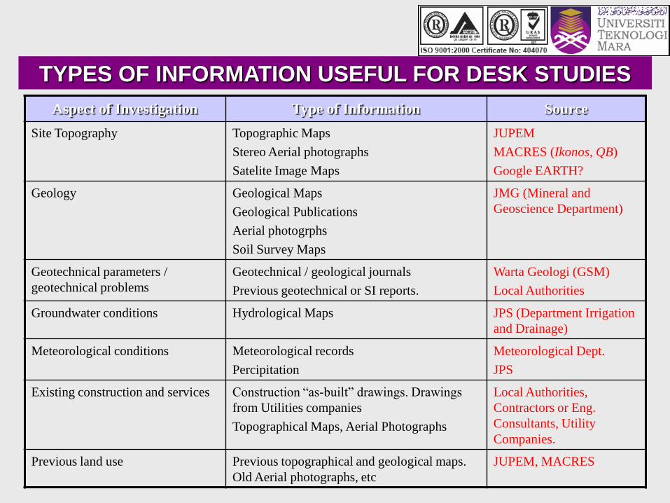
TYPES OF INFORMATION USEFUL FOR DESK STUDIES

Aspect of Investigation Type of Information Source

Site Topography Topographic Maps

Stereo Aerial photographs

Satelite Image Maps

JUPEM

MACRES (Ikonos, QB)

Google EARTH?

Geology Geological Maps

Geological Publications

Aerial photogrphs

Soil Survey Maps

JMG (Mineral and

Geoscience Department)

Geotechnical parameters /

geotechnical problems

Geotechnical / geological journals

Previous geotechnical or SI reports.

Warta Geologi (GSM)

Local Authorities

Groundwater conditions Hydrological Maps JPS (Department Irrigation

and Drainage)

Meteorological conditions Meteorological records

Percipitation

Meteorological Dept.

JPS

Existing construction and services Construction “as-built” drawings. Drawings

from Utilities companies

Topographical Maps, Aerial Photographs

Local Authorities,

Contractors or Eng.

Consultants, Utility

Companies.

Previous land use Previous topographical and geological maps.

Old Aerial photographs, etc

JUPEM, MACRES

The Site Reconnaissance Survey or the Walk-Over Survey is

an important and necessary supplement to Desk Study and

should cover the whole site area and the immediate vicinity.

SITE RECONNAISSANCE SURVEY

To compare & confirm desk study & obtain additional information

Physically examine ground conditions, geotechnical hazards, exposed cut/geology, outcrop, weathering depth, previous slip, adjacent structures, etc.

Give due consideration to environment & ecological impact.

Execute brief geological mapping

Questioning local individuals: flood & tide levels, etc.

Example Checklist form for Site Reconnaissance

MAIN SUBSURFACE EXPLORATION

Developing a Site Investigation Program

For many projects and for many site conditions, the most

difficult and crucial part of the planning phase involves the

decisions regarding sampling/investigation method, boring

locations, number of samples, number and types of laboratory

tests, and the number of confirmatory samples.

At this stage, the types of potential sampling/investigation

methods should have been identified and assessed.

HOW MANY BOREHOLES?

Example : A proposed site for multi-storey complex

Not enough boreholes, soil profile and properties not well defined

Borehole point

Too many boreholes and will blow the budget

Borehole point

HOW MANY BOREHOLES?

Example : A proposed site for multi-storey complex

About right

Borehole point

Trial pit

Here, we strike a good balance. Trial pits are quite cheap, and they certianly have a place in site investigation.

HOW MANY BOREHOLES?

Example : A proposed site for multi-storey complex

5.1 JKR/Mackintosh Probes

5.2 Hand Augering (HA)

5.3 Deep Boring (DB)

5.4 Deep Sound (DS) -100/200 kN Capacity

5.5 Test Pits, Bulk & Block Samples

5.6 Motorised Hand Boring (MHB)

5.7 Geophysical Survey

5.0 Common SI Methods.

CONVENTIONAL APPROACH TO SI

5.1 JKR/Mackintosh Probe

Can be used to determine the

thickness of unsuitable material to be

removed and also for preliminary

design of embankments

Limited to about 15 m

Record no. of blows/ft. then correlate

to established chart to determine

bearing capacity of soil

CONVENTIONAL APPROACH TO SI

5.2 Hand Augering (HA)

Used in soft to stiff cohesive soils or

sandy soils above water tables

Maximum depth about 5 m

CONVENTIONAL APPROACH TO SI

COMMON TYPES OF HAND AUGER

TECHNIQUE FOR RECORDING A

REPRESENTATIVE SOIL PROFILE

USING A HAND AUGER

HAND AUGERING (HA)

Used in soft to stiff

cohesive soils or sandy

soils above water table.

Maximum depth up to 5 m.

Can be used to obtained

open tube samples of 50 –

100 mm diameter

5.2 Hand Augering (HA)

CONVENTIONAL APPROACH TO SI

CONVENTIONAL APPROACH TO SIPercussion Drilling

CONVENTIONAL APPROACH TO SI

5.3 Deep Boring (DB)

Advanced by power rotary drilling

Open hole rotary drilling or casing

advancement drilling method

Flushing medium.. Clear water, mud

water, etc

Bentonite/mud water for coarse

sand/fine gravel

CONVENTIONAL APPROACH TO SI

5.3 Deep Boring (DB)

CONVENTIONAL APPROACH TO SI

WASH / ROTARY BORING WATER JETTING

Rig with

hydraulic feedRig

Water pump

casing

rod

Drill bit

Water

pump

casing

METHODS OF ADVANCING BOREHOLES

Water under very high

pressure

Return water outside of

casing, making all related

observations useless

Casing

Hole advanced by brute jetting

action of water and rotating

and surging of casing

Huge volume of soil below is

disturbed, water ingress is

very high and test volume is

no longer intact. All tests /

samples are bad

Hole advanced by jetting of high

pressure water downwards into the

soil below and surging and rotating

action of casing. Hole advanced

mainly by destructive forces of water

under high pressure.

Return water Outside of casing

Cheap adapted machine. Very fast and

cost less.

Test volume disturbed and altered.

Samples and tests not representative or

bad.

NO skil is required.

NOT in compliance with specification

requiring sampling and testing or code

of practice.

WATER JETTING

WASH BORING

Hole advanced by rotating and

surging action of cutting bit attached

to drill rod inside casing. Water

discharged sideways and downwards

into soils below

Return water Inside of casing

Machine various including manual. More

suited for drilling water wells and boring

for disturbed samples.

Test volume disturbed and altered.

Samples and tests not representative or

reliable.

Require some skill

Doubtful compliance with specification

requiring sampling and testing or code

of practice.

Water under pressure

Drill rod

Return water inside of casing,

making related observations

possible

Casing

Hole advanced rotating and

surging of bit attached to drill

string

Cutting bit

Most flushing water discharged

downwards, some water enters

soils below. With care, only

some tests samples are

possible.

Hole advanced by cutting bit attached to

the bottom of drill rod and hydraulic thrust.

Soil cuttings transported upward by drilling

water. Use compatible casings, rods, drag

and cutting bits. Cutting bits varying with

soil types. Almost all water discharged

sideways.

Return water inside of casing

Machine suited for quality sampling and

testing. High degree of observations possible

– e.g. return water, water losses, penetration

rates, etc.

Rig very costly

Test volume intact, samples acceptable,

reliable.

Skill essential

In compliance with specification requiring

sampling and testing and code of practice.

ROTARY BORING

Water under pressure

Compatible drill rod

Hole advanced by cutting

action of rotating bit attached

to drill rod and hydraulic thrust

Compatible casing

Return water inside of casing

making related observations

possible

Cutting bit

Almost all flushing water

discharged sideways, very little

ingress into soil below. Very

little disturbance to soil volume

below.

Good tests and samples are

possible

ROTARY DRILLING MACHINE

ROTARY WASH DRILLING SYSTEM

STRATIGRAPHY IDENTIFICATION AND BOREHOLE LOG/RECORD

The subsurface conditions observed in

the soil samples and drilling cuts or

perceived through the performance of

the drilling should be described by the

driller.

In addition to the description of

individual samples, the boring log

should also describe various strata

COMMON FIELD TESTS

STANDARD PENETRATION TEST (SPT)

STANDARD PENETRATION TEST (SPT)

Drive head

Split tube

Drive shoe

76 mm

457 mm

76 mm

Split-spoon sampler

Drop hammer

Extension

rod

Split spoon

sampler

borehole

50 mm

SPT test in borehole

SEQUENCE OF DRIVING SPLIT BARREL SAMPLER DURING THE

STANDARD PENETRATION TEST (SPT)

5.4 Deep Sound (DS)

Static Dutch Cone Penetrometer

Used to supplement Deep Boring (DB)

results in filling areas which are fluvial

or soft formation

Not suitable for gravel abundant

subsoil

CONVENTIONAL APPROACH TO SI

Cone Penetration Equipment

FIELD RESULTS & ANALYSIS I

CONE PENETRATION TEST

FIELD RESULTS & ANALYSIS I

5.5 Test Pit, Bulk & Block Samples

Usually to access suitability of soil as

filling material

Up to 2 m or more (with excavator)

Visual inspection in Test Pit

Bulk samples for Laboratory Tests

Undisturbed block for Strength Test

CONVENTIONAL APPROACH TO SI

CLAY

BOREHOLE75 mm dia

10-30 m depth

back hoeBoring rig

METHODS OF EXPLORATION

Hand Augering (HA)

JKR / Mackintosh Probes

Deep Sounding (DS)

TRIAL PIT1-2 m width2-4 m depth

Other exploration methods :

An engineer supervising and marking

samples from trial pitTrial pit showing soil Profiles

TRIAL PIT

A Very Large Trial Pit

Enables visual inspection, locating strata boundaries, and access for undisturbed block samples.

TRIAL PIT

5.5 Test Pit, Bulk & Block Samples

CONVENTIONAL APPROACH TO SI

5.7 Geophysical Survey

Used to supplement borehole results

covering large areas

Include seismic refraction method &

electrical resistivity method

Can be used to predict corrosivity of

soil & geological features and cavities

CONVENTIONAL APPROACH TO SI

5.7 Geophysical Survey

Electrical Resistivity Method

Seismic Refraction Method

CONVENTIONAL APPROACH TO SI

SOIL AND ROCK SAMPLING

Soil samples obtained for engineering testing and analysis, in general, are of two

main categories:

Undisturbed Samples

Undisturbed samples are obtained in clay soil strata for use in laboratory testing to

determine the engineering properties of those soils. Undisturbed samples of

granular soils can be obtained, but often specialized procedures are required such

as freezing or resin impregnation and block or core type sampling.

Undisturbed samples are obtained with specialized equipment designed to

minimize the disturbance to the in-situ structure and moisture content of the soils.

Specimens obtained by undisturbed sampling methods are used to determine the

strength, stratification, permeability, density and compressibility properties

Disturbed Samples

Disturbed samples are those obtained using equipment that destroy the macro

structure of the soil but do not alter its mineralogical composition. Specimens from

these samples can be used for determining the general lithology of soil deposits, for

identification of soil components and for general classification purposes (grain size

distribution, Atterberg limits) and compaction characteristics of soils.

DISTURBED SAMPLES OBTAINED FROM SPT

UNDISTURBED CLAY SAMPLES

Required for triaxial, consolidation tests in the lab.

sampling tube

soil (%) 100..

....2

22

DI

DIDOAR

area ratio

AR<10%

Good quality samples necessary.

The thicker the wall, the greater the disturbance.

Take good care in transport and handling.

ROCK CORING

CONVENTIONAL APPROACH TO SI


Recommended