31
Software Engineering System Models Slide 1 Software Engineering System Models
| Date post: | 13-Jul-2015 |
| Category: |
Engineering |
| Upload: | mahmoud-saaideh |
| View: | 84 times |
| Download: | 0 times |

Software Engineering System Models Slide 1
Software Engineering
System Models

Software Engineering System Models Slide 2
System models
are abstract descriptions of systems
whose requirements are being analysed
Software Engineering System Models Slide 3
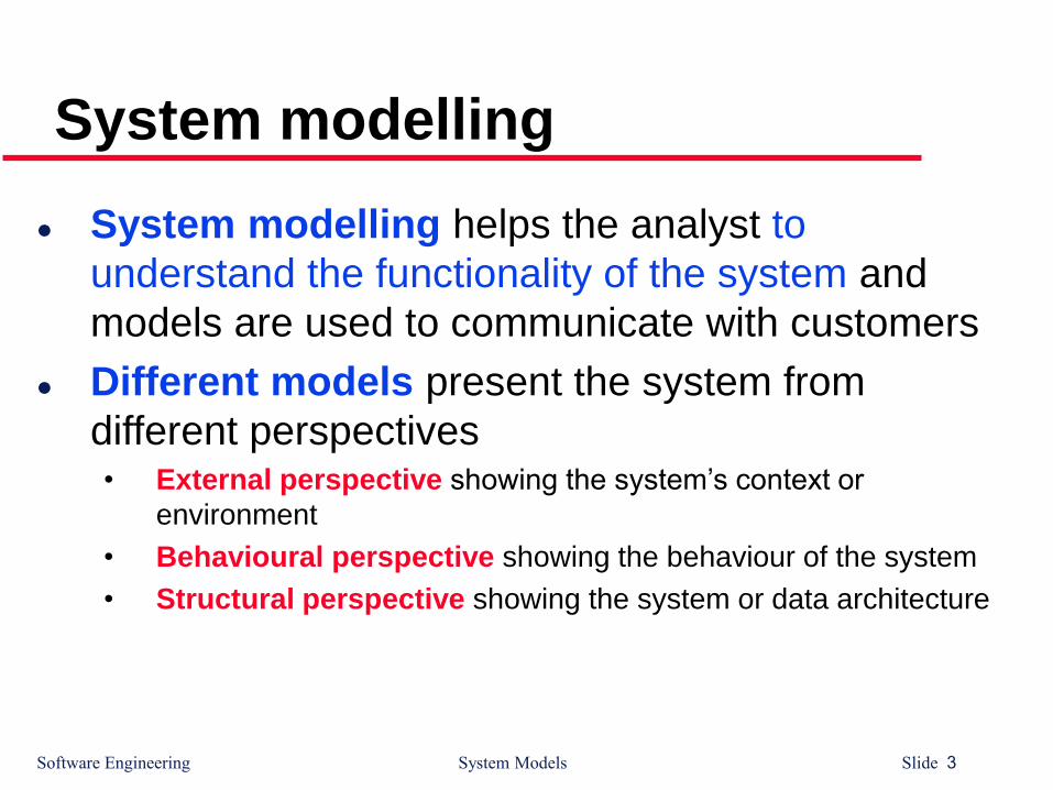
System modelling
System modelling helps the analyst to
understand the functionality of the system and
models are used to communicate with customers
Different models present the system from
different perspectives• External perspective showing the system’s context or
environment
• Behavioural perspective showing the behaviour of the system
• Structural perspective showing the system or data architecture

Software Engineering System Models Slide 4
System models weaknesses
They do not model non-functional system
requirements
They do not usually include information
about whether a method is appropriate for a
given problem
They may produce too much documentation
The system models are sometimes too
detailed and difficult for users to understand

Software Engineering System Models Slide 5
Model types
Data processing model showing how the data is
processed at different stages
Composition model showing how entities are composed
of other entities
Architectural model showing principal sub-systems
Classification model showing how entities have common
characteristics
Stimulus/response model showing the system’s reaction
to events

Software Engineering System Models Slide 6
Context models
Context models are used to illustrate the
boundaries of a system
Social and organisational concerns may affect
the decision on where to position system
boundaries
Architectural models show the a system and
its relationship with other systems
Software Engineering System Models Slide 7
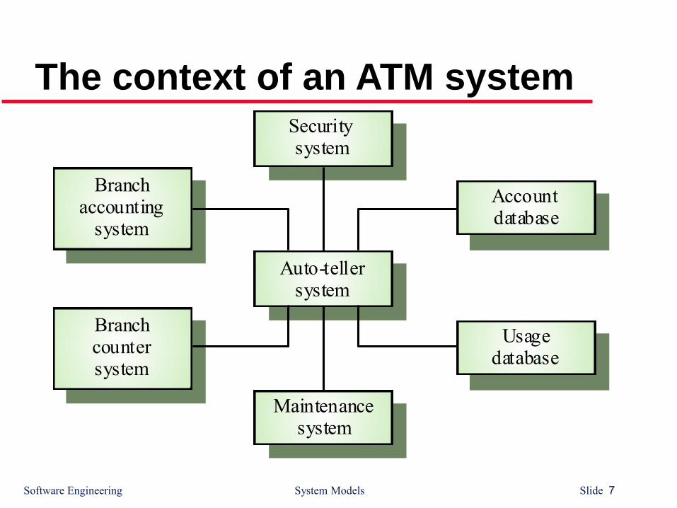
The context of an ATM system
Auto-tellersystem
Securitysystem
Maintenancesystem
Accountdatabase
Usagedatabase
Branchaccounting
system
Branchcountersystem

Software Engineering System Models Slide 8
Process models
Process models show the overall process and
the processes that are supported by the system
Data flow models may be used to show the
processes and the flow of information from one
process to another

Software Engineering System Models Slide 9
Equipment procurement process
Get costestimates
Acceptdelivery ofequipment
Checkdelivered
items
Validatespecification
Specifyequipmentrequired
Choosesupplier
Placeequipment
order
Installequipment
Findsuppliers
Supplierdatabase
Acceptdelivered
equipment
Equipmentdatabase
Equipment
spec.Checked
spec.
Deliverynote
Deliverynote
Order
notification
Installationinstructions
Installationacceptance
Equipmentdetails
Checked andsigned order form
Orderdetails +
Blank orderform
Spec. +supplier +estimate
Supplier listEquipment
spec.

Software Engineering System Models Slide 10
Behavioural models
Behavioural models are used to describe the
overall behaviour of a system
Two types of behavioural model• Data processing models that show how data is processed as it
moves through the system
• State machine models that show the systems response to
events
Both of these models are required for a
description of the system’s behaviour

Software Engineering System Models Slide 11
Data-processing models
Data flow diagrams are used to model the
system’s data processing
These show the processing steps as data flows
through a system
IMPORTANT part of many analysis methods
Simple and intuitive notation that customers
can understand
Show end-to-end processing of data

Software Engineering System Models Slide 12
Order processing DFD
Completeorder form
Orderdetails +
blank
order form
Valida teorder
Recordorder
Send tosupplier
Adjustavailablebudget
Budgetfile
Ordersfile
Completedorder form
Signedorder form
Signedorder form
Checked andsigned order
+ ordernotification
Orderamount
+ accountdetails
Signedorder form
Orderdetails

Software Engineering System Models Slide 13
Data flow diagrams
DFDs model the system from a functional
perspective
Tracking and documenting how the data
associated with a process is helpful to develop
an overall understanding of the system
Data flow diagrams may also be used in
showing the data exchange between a system
and other systems in its environment

Software Engineering System Models Slide 14
2.2 State machine models
State Machine models the behaviour of the system in response to external and internalevents
They show the system’s responses to stimuli so are often used for modelling real-time systems
State machine models show system states as nodes and events as arcs between these nodes. When an event occurs, the system moves from one state to another
Statecharts are an integral part of the UML

Software Engineering System Models Slide 15
Microwave oven modelFull power
Enabled
do: operateoven
Fullpower
Halfpower
Halfpower
Fullpower
Number
TimerDooropen
Doorclosed
Doorclosed
Dooropen
Start
do: set power = 600
Half power
do: set power = 300
Set time
do: get numberexit: set time
Disabled
Operation
Timer
Cancel
Waiting
do: display time
Waiting
do: display time
do: display 'Ready'
do: display 'Waiting'
State machine model
does not show flow of
data within the system

Software Engineering System Models Slide 16
Microwave oven stimuli
Stimulus DescriptionHalf power The user has pressed the half power buttonFull power The user has pressed the full power buttonTimer The user has pressed one of the timer buttonsNumber The user has pressed a numeric keyDoor open The oven door switch is not closedDoor closed The oven door switch is closedStart The user has pressed the start buttonCancel The user has pressed the cancel button

Software Engineering System Models Slide 17
Finite state machines
Finite State Machines (FSM), also known as
Finite State Automata (FSA)
are models of the behaviours of a system or acomplex object, with a limited number of definedconditions or modes, where mode transitionschange with circumstance.
Software Engineering System Models Slide 18
Finite state machines - Definition
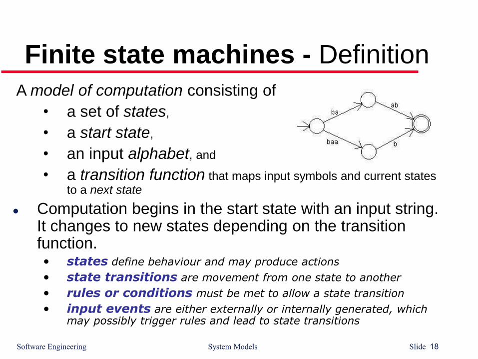
A model of computation consisting of
• a set of states,
• a start state,
• an input alphabet, and
• a transition function that maps input symbols and current states to a next state
Computation begins in the start state with an input string. It changes to new states depending on the transition function. • states define behaviour and may produce actions
• state transitions are movement from one state to another
• rules or conditions must be met to allow a state transition
• input events are either externally or internally generated, which may possibly trigger rules and lead to state transitions
Software Engineering System Models Slide 19
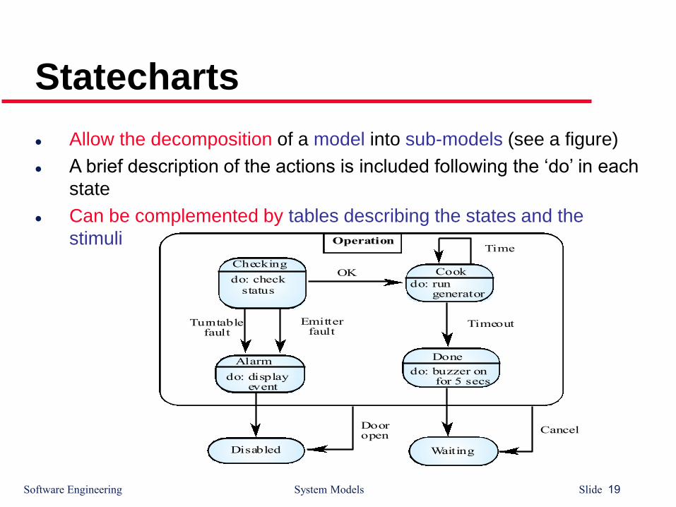
Statecharts
Allow the decomposition of a model into sub-models (see a figure)
A brief description of the actions is included following the ‘do’ in each
state
Can be complemented by tables describing the states and the
stimuli
Cook
do: run generator
Done
do: buzzer on for 5 secs.
Waiting
Alarm
do: display event
do: checkstatus
Checking
Turntablefault
Emitterfault
Disabled
OK
Timeout
TimeOperation
Dooropen
Cancel
Software Engineering System Models Slide 20
Petri Nets Model
Petri Nets were developed originally by Carl Adam Petri, and were the subject of his dissertation in 1962.
Since then, Petri Nets and their concepts have been extended, developed, and applied in a variety of areas.
While the mathematical properties of Petri Nets are interesting and useful, the beginner will find that a good approach is to learn to model systems by constructing them graphically.

Software Engineering System Models Slide 21
The Basics
A Petri Net is a collection of
directed arcs connecting places
and transitions.
Places may hold tokens.
The state or marking of a net is
its assignment of tokens to
places.
Place with
token
P1
P2
T1
Arc with capacity 1
TransitionPlace

Software Engineering System Models Slide 22
Capacity
Arcs have capacity 1 by default; if other than
1, the capacity is marked on the arc.
Places have infinite capacity by default.
Transitions have no capacity, and cannot store
tokens at all.
Arcs can only connect places to transitions
and vice versa.
A few other features and considerations will be
added as we need them.

Software Engineering System Models Slide 23
Enabled transitions and firing
A transition is enabled when the number of tokens in
each of its input places is at least equal to the arc weight
going from the place to the transition.
An enabled transition may fire at any time.
Software Engineering System Models Slide 24
When arcs have different weights…
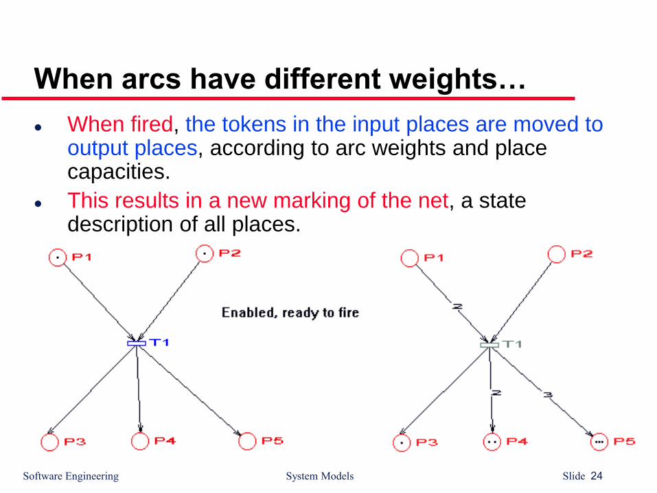
When fired, the tokens in the input places are moved to output places, according to arc weights and place capacities.
This results in a new marking of the net, a state description of all places.
Software Engineering System Models Slide 25
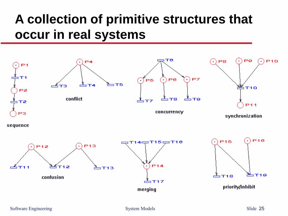
A collection of primitive structures that
occur in real systems

Software Engineering System Models Slide 26
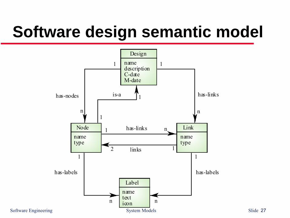
Semantic data models
Used to describe the logical structure of dataprocessed by the system
Entity-relation-attribute model sets out the entities in the system, the relationships between these entities and the entity attributes
Widely used in database design. Can readily be implemented using relational databases
No specific notation provided in the UML but objects and associations can be used
Software Engineering System Models Slide 27
Software design semantic modelDesign
namedescriptionC-dateM-date
Link
nametype
Node
nametype
links
has-links
12
1 n
Label
nametexticon
has-labelshas-labels
1
n
1
n
has-linkshas-nodes is-a
1
n
1
n1
1
Software Engineering System Models Slide 28
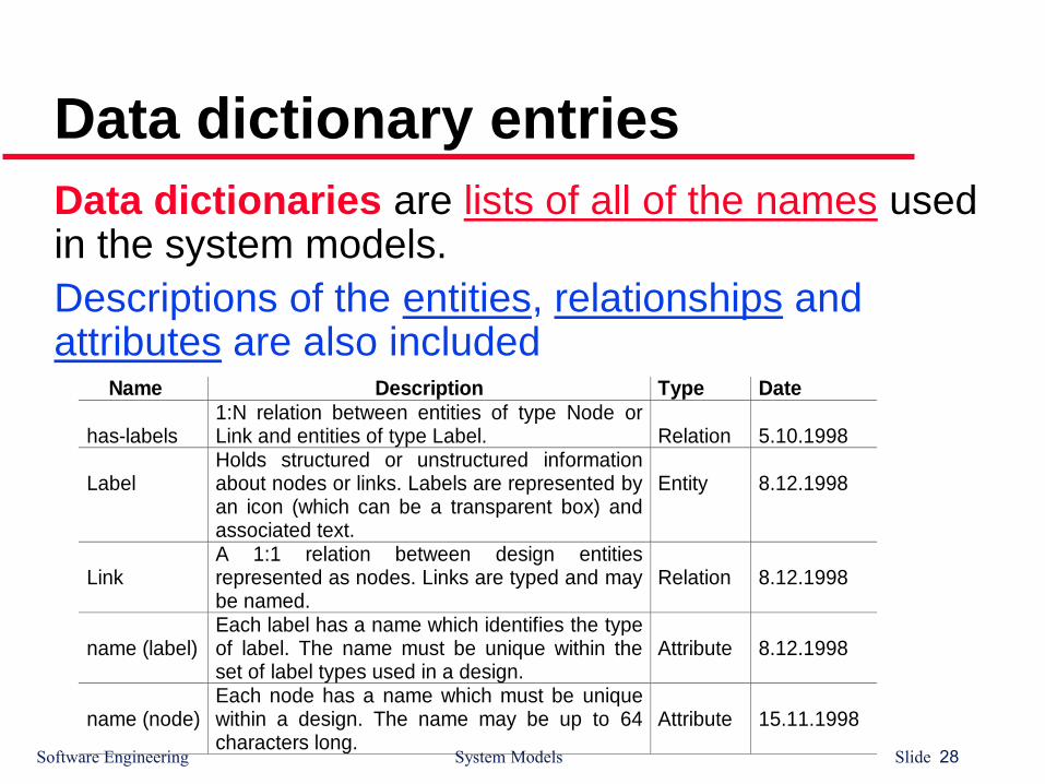
Data dictionary entries
Name Description Type Date
has-labels1:N relation between entities of type Node orLink and entities of type Label. Relation 5.10.1998
LabelHolds structured or unstructured informationabout nodes or links. Labels are represented byan icon (which can be a transparent box) andassociated text.
Entity 8.12.1998
LinkA 1:1 relation between design entitiesrepresented as nodes. Links are typed and maybe named.
Relation 8.12.1998
name (label)Each label has a name which identifies the typeof label. The name must be unique within theset of label types used in a design.
Attribute 8.12.1998
name (node)Each node has a name which must be uniquewithin a design. The name may be up to 64characters long.
Attribute 15.11.1998
Data dictionaries are lists of all of the names used in the system models.
Descriptions of the entities, relationships and attributes are also included

Software Engineering System Models Slide 29
Object models
Object models describe the system in terms
of object classes
An object class is an abstraction over a set of
objects with common attributes and the services
(operations) provided by each object
Various object models may be produced• Inheritance models
• Aggregation models
• Interaction models

Software Engineering System Models Slide 30
Object models
Natural ways of reflecting the real-world entities
manipulated by the system
More abstract entities are more difficult to model
using this approach
Object class identification is recognised as a
difficult process requiring a deep understanding
of the application domain
Object classes reflecting domain entities are
reusable across systems
Software Engineering System Models Slide 31
The Unified Modeling Language
Devised by the developers of widely used object-oriented
analysis and design methods
Has become an effective standard for object-oriented
modelling
Notation• Object classes are rectangles with the name at the top, attributes in
the middle section and operations in the bottom section
• Relationships between object classes (known as associations) are
shown as lines linking objects
• Inheritance is referred to as generalisation and is shown ‘upwards’
rather than ‘downwards’ in a hierarchy


