17
| Date post: | 13-Jul-2015 |
| Category: |
Education |
| Upload: | akmal-ariffin |
| View: | 96 times |
| Download: | 0 times |


Define motions of all actuators
Divide sequence into groups
Determine limit switch status
Identify number of connecting line
( = number of groups)
Identify number of reversing valve
( = number of groups – 1)

Example ◦ A pneumatic actuated
drilling machine, contained of two DAC. When the workpiece is located at it position, cylinder A will clamp the workpiece. Then, the drilling process is started, where the spindle is controlled by cylinder B. After finish drilling, cylinder B will retract to the initial position, before the clamping cylinder retract.
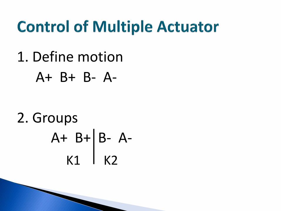
1. Define motion
A+ B+ B- A-
2. Groups
A+ B+ B- A-
K1 K2

3. Limit switch status
A+ B+ B- A-
Start
A1
B1
B0
A0
Above
Below

4. Number of connecting line
= number of groups
= 2
5. Number of reversing valve
= number of groups – 1
= 1

Mechanical sensor, initial position
Activated position

2 connecting lines
1 reversing valve

A+ Start + A0

B+ A1

B- B1

A- B0


4 2
5
1
3
14 12
0 V

4 2
5
1
3
14 12
4 2
5
1
3
14 12
0 V6
0 V5


