24
1 Welcome to the EPTAC Webinar Series: Delamination, Causes and Cures? You are connected to our live presentation delivered via the internet. The webinar will begin shortly. NEW

1
Welcome to the EPTAC Webinar Series:Delamination, Causes and Cures?
You are connected to our live presentation delivered via the internet. The webinar will begin shortly.
NEW

2
Attendee Quick Reference
Control Panel Features:Once you have joined our Webinar, you will see this GoToWebinar Control Panel and Grab Tab. The control panel contains three panes that can be expanded or collapsed by clicking the arrow on the left side of each pane.
To Leave a Webinar:1. From the Attendee Control Panel File Menu, select Exit – Leave Webinar.2. On the Leave Webinar?Confirmation dialog box, click Yes.
You can ask questions by typing text directly to the presenter using the “Question and Answer” box

Delamination, Causes and Cures

4
Delamination
What is it?
Why is measles not delamination?
Why is Haloing not delamination?
Is Crazing a form of delamination?

5
What is it?
It is a separation of either the fiberglass from the resin or
The resin from the laminate or foil, like the prepreg or B stage.

6
What Causes Delamination
Thermal shock Wave solder process Manual soldering Rework and Repair process
Moisture in the board Poor lamination process Wrong Tg for FR-4 material

7
What Can Help Prevent Delamination
Oxide layer on inner layers
Baking of board prior to thermal processing
Keeping them dry in storage
Qualification of supplier to provide boards that are acceptable to the process

8
Some Typical Stress Testing Parameters
Solder Float test 6X @ 288oC
Interconnect Stress Test 6X @ 230oC
n passes in reflow simulation at 260oC
Time at 260oC must be greater than 10 minutes.

9
Types of Tests to Measure Delamination
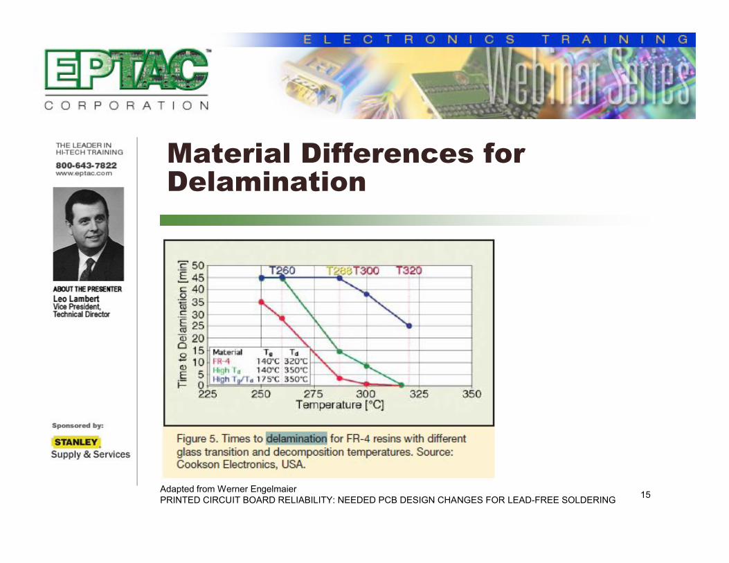
Time to delamination is a common measurement used to assess base material performance.
The time to delamination is a measure of the time it takes for the resin and copper, or resin and reinforcement, to separate or delaminate.
This test utilizes TMA equipment to bring a sample to a specified temperature and then measures the time it takes for failure to occur.
An Assessment of the Impact of Lead-Free Assembly Processes on BaseMaterial and PCB ReliabilityEdward KelleyCookson Electronics, Polyclad LaminatesLondonderry, NH

10
Types of Tests to Measure Delamination
Temperatures of 260oC (T260) and 288oC (T288) are commonly used for this testing.
Many high-Tg FR-4 materials will exhibit lower times to delamination than low-Tg FR-4 materials.
With Pb-free assembly temperatures reaching 260oC, the T260 test has become a much more relevant measure of performance.
An Assessment of the Impact of Lead-Free Assembly Processes on BaseMaterial and PCB ReliabilityEdward KelleyCookson Electronics, Polyclad LaminatesLondonderry, NH

11
Delamination Illustration
Adapted from IPC-A-600

12
Microsection Delamination Example
Microsection of laminate separation from the internal foil.
Adapted from IPC-A-600

13
External Example
This happened after the wave soldering process.
Provided by Assurance Technology Corporation

14
Microsection example
Adapted from “Final Finishes and Laminate Lead Free Overview”by Joe Renda Enthone OEM Manager
15
Material Differences for Delamination
Adapted from Werner EngelmaierPRINTED CIRCUIT BOARD RELIABILITY: NEEDED PCB DESIGN CHANGES FOR LEAD-FREE SOLDERING

16
Measles: Definition and Causes
Are a form of separation They occurs at the knuckles of the fiber
bundles and look like a cross when viewed externally
Causes can be many, but basically poor preparation of the fiber, lack of wetting of the epoxy and excessive pressure applied during soldering
Measles will not propagate with exposure to thermal cycle

17
Example of Measles

18
Crazing: Definition and Cause
It is a separation along the fiber bundles
Most times it is caused by mechanical means, such as bending the boards.

19
Crazing
Crazing is much less controlled separation in the base material forming ‘‘interconnections’’between measles and possibly adjacent conductive patterns;
Therefore, the acceptance requirements for crazing were set the same as the similar conditions of delamination and blistering.
From IPC-A-600

20
Crazing Pictures
Adapted from IPC-A-600
21
Haloing: Definition and Causes
Is a separation of the epoxy from the glass, It occurs either along the edges of the
board or around the circumference of a drilled hole. Therefore there is a special criteria for its acceptance and non-conformance
Board separation process and bad drilling process

22
Haloing
On Edges
On internal holes

23
Upcoming Webinars
New Webinars added every month.
Check back at:
http://www.eptac.com/webinars/upcoming.htm
Or contact us at: 1.800.643.7822
24
Further Information
For questions regarding this webinar, please contact Leo Lambert at
For information on any of EPTAC’s or IPC’s Certification Courses, please visit our
website at http://www.eptac.com


![WELCOME [fairtrade.london.anglican.org]fairtrade.london.anglican.org/Main pages/FTfortnightaction_guide_2009.pdfWELCOME Welcome to the Fairtrade Fortnight Action Guide for 2009! This](https://static.documents.pub/doc/80x56/5f08fbfd7e708231d424ac93/welcome-pagesftfortnightactionguide2009pdf-welcome-welcome-to-the-fairtrade.jpg)


![Welcome [] Carpet101_3_9_06.pdfWelcome . CARPET101 ... Difficult to Re-process Polymer Not recyclable into virgin Nylon ... Gauge, Fabric formation, dye technique](https://static.documents.pub/doc/80x56/5abaeeb07f8b9a297f8c4f42/welcome-carpet1013906pdfwelcome-carpet101-difficult-to-re-process.jpg)