HERVE
BARON
©2
01
3 –
He
rvé
Ba
ron
Welcome to this presentation.
It shows the different types of Process diagrams and will help
you to read them.
It also provides you with reference information as to their
contents.
Comments are most welcome ([email protected]),
which I will incorporate for the benefit of all.
Hervé
Process Diagrams Training
HERVE
BARON
©2
01
3 –
He
rvé
Ba
ron
Agenda
� The Process Diagrams
• The Block Flow Diagram (BFD)
• The Process Flow Diagram (PFD)
• The Piping & Instrumentation Diagram (P&ID)
�The various types of P&IDs
�The different revisions of the P&IDs
• Other Process diagrams
• Quiz
HERVE
BARON
©2
01
3 –
He
rvé
Ba
ron
Guess
What is this drawing?
HERVE
BARON
©2
01
3 –
He
rvé
Ba
ron
The Block Flow Diagram
HERVE
BARON
©2
01
3 –
He
rvé
Ba
ron
The Block Flow Diagram
� Results from the high level functional requirements of the plant
� Depicts the various Processes carried out within the facility and their sequence
� Shows the inputs (feed) and outputs (products)
� The item of the BFD is the Process Unit
HERVE
BARON
©2
01
3 –
He
rvé
Ba
ron
Guess
What is this drawing?
HERVE
BARON
©2
01
3 –
He
rvé
Ba
ron
The Process Flow Diagram (PFD)
HERVE
BARON
©2
01
3 –
He
rv
é B
aro
n
The Process Flow Diagram (PFD)
Process Flow Diagram
HERVE
BARON
©2
01
3 –
He
rvé
Ba
ron
The Process Flow Diagram (PFD)
� Results from process simulations
� Depicts the various Equipment within a Process (or Utility) Unit and their sequence
� Shows the process controls
� The individual drawing item of the PFD is the Equipment Item
HERVE
BARON
©2
01
3 –
He
rvé
Ba
ron
Scheme that includes the following information, as a minimum:
� Main equipment (all the itemized ones),
� Process lines between equipment,
� All control loops and main instruments,
� For each stream, indication of:
• Temperature
• Pressure
• Composition
• Specific gravity
• Operating density
• Heat content
• Flow rate (relevant to each phase)
� Design conditions of main equipment.
� It shall be drawn-up according to ISA 6.12 regulation as far as symbology is concerning
The Process Flow Diagram (PFD)
HERVE
BARON
©2
01
3 –
He
rvé
Ba
ron
The Process Flow Diagram (PFD)
Heat and
material
balance
HERVE
BARON
©2
01
3 –
He
rvé
Ba
ron
Guess
What type of diagram is this?
HERVE
BARON
©2
01
3 –
He
rvé
Ba
ron
The Piping & Instrumentation Diagram (P&ID)
HERVE
BARON
©2
01
3 –
He
rvé
Ba
ron
Piping & Instrumentation Diagrams (P&IDs)
“a document that clearly identifies the equipment in the physico-
chemical process and the circulation of fluids between these
equipment items. It also shows the piping systems and control
devices necessary for unit operation as well as the specific
requirements to be taken into account for the design of systems.”
The PFD is a detailing of the PFD that show all lines, instruments
necessary for the operation, monitoring, control and
maintenance around individual equipment.
HERVE
BARON
©2
01
3 –
He
rvé
Ba
ron
Piping & Instrumentation Diagram (P&ID)
HERVE
BARON
©2
01
3 –
He
rvé
Ba
ron
Piping & Instrumentation Diagram (P&ID)
What information
does a P&ID contain?
HERVE
BARON
©2
01
3 –
He
rvé
Ba
ron
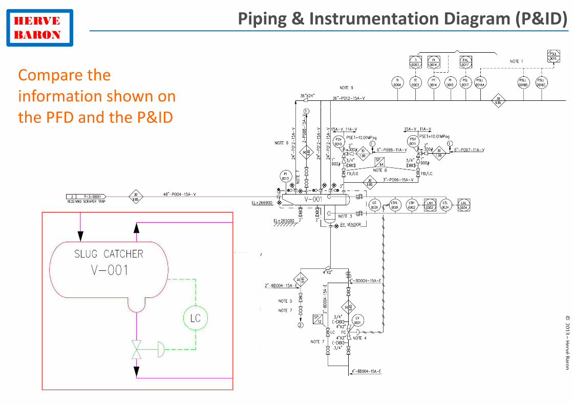
Piping & Instrumentation Diagram (P&ID)
Compare the
information shown on
the PFD and the P&ID
HERVE
BARON
©2
01
3 –
He
rvé
Ba
ron
Piping & Instrumentation Diagram (P&ID)
Compare the
information shown on
the PFD and the P&ID
HERVE
BARON
©2
01
3 –
He
rvé
Ba
ron
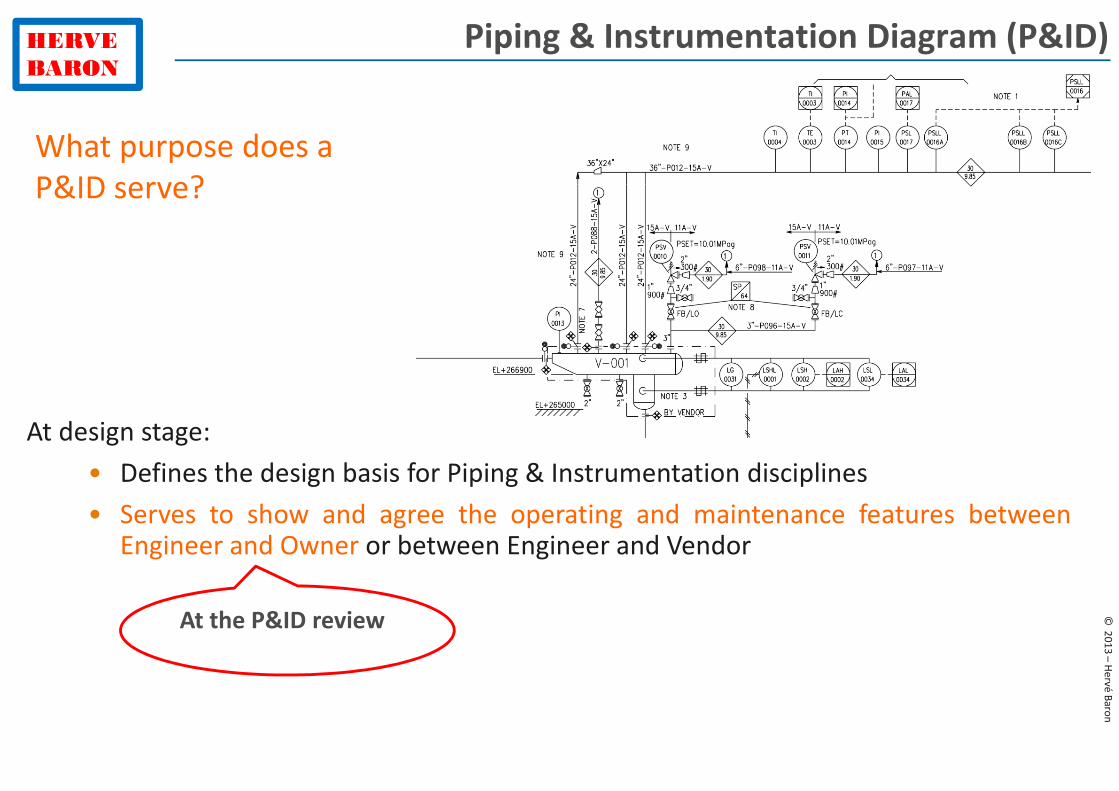
Piping & Instrumentation Diagram (P&ID)
At design stage:
What purpose does a
P&ID serve?
HERVE
BARON
©2
01
3 –
He
rvé
Ba
ron
Piping & Instrumentation Diagram (P&ID)
At design stage:
• Defines the design basis for Piping & Instrumentation disciplines
What purpose does a
P&ID serve?
HERVE
BARON
©2
01
3 –
He
rvé
Ba
ron
Piping & Instrumentation Diagram (P&ID)
At design stage:
• Defines the design basis for Piping & Instrumentation disciplines
• Serves to show and agree the operating and maintenance features betweenEngineer and Owner or between Engineer and Vendor
What purpose does a
P&ID serve?
At the P&ID review
HERVE
BARON
©2
01
3 –
He
rvé
Ba
ron
Piping & Instrumentation Diagram (P&ID)
At design stage:
• Defines the design basis for Piping & Instrumentation disciplines
• Serves to show and agree the operating and maintenance features betweenEngineer and Owner or between Engineer and Vendor
What purpose does a
P&ID serve?
What are the main items that are discussed during the P&ID review?
At the P&ID review
HERVE
BARON
©2
01
3 –
He
rvé
Ba
ron
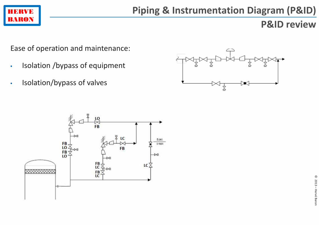
Piping & Instrumentation Diagram (P&ID)
P&ID review
Ease of operation and maintenance:
• Isolation /bypass of equipment
HERVE
BARON
©2
01
3 –
He
rvé
Ba
ron
Piping & Instrumentation Diagram (P&ID)
P&ID review
Ease of operation and maintenance:
• Isolation /bypass of equipment
• Isolation/bypass of valves
HERVE
BARON
©2
01
3 –
He
rvé
Ba
ron
Piping & Instrumentation Diagram (P&ID)
P&ID review
Ease of operation and maintenance:
• Isolation /bypass of equipment
• Isolation/bypass of valves
• Vents/drains
HERVE
BARON
©2
01
3 –
He
rvé
Ba
ron
Piping & Instrumentation Diagram (P&ID)
At design stage:
• Defines the design basis for Piping & Instrumentation disciplines
• Serves to show and agree the operating and maintenance features betweenEngineer and Owner or between Engineer and Vendor
What purpose does a
P&ID serve?
HERVE
BARON
©2
01
3 –
He
rvé
Ba
ron
Review/comment of the design
Scope of supply: counter flange to be
supplied by vendor, as per contractual specification
Decision during a clarification meeting with vendor, for instance to
allow maintenance
Comments on Instrument numbering
and installation: Vendor P&ID shall use the same nomenclature
than project’s P&ID
Missing information: setting pressure of PCV shall be indicated
on P&ID
HERVE
BARON
©2
01
3 –
He
rvé
Ba
ron
Piping & Instrumentation Diagram (P&ID)
At design stage:
• Defines the design basis for Piping & Instrumentation disciplines
• Serves to show and agree the operating and maintenance features betweenEngineer and Owner or between Engineer and Vendor
• Serves to show the interface with equipment/package vendors
What purpose does a
P&ID serve?
HERVE
BARON
©2
01
3 –
He
rvé
Ba
ron
Piping & Instrumentation Diagram (P&ID)
At design stage:
• Defines the design basis for Piping & Instrumentation disciplines
• Serves to show and agree the operating and maintenance features betweenEngineer and Owner or between Engineer and Vendor
• Serves to show the interface with equipment/package vendors
• Perform HAZOP review
What purpose does a
P&ID serve?
HERVE
BARON
©2
01
3 –
He
rvé
Ba
ron
Hazard and Operability Review (HAZOP)
Too much, too little, no
Flow, Pressure, Temperature
HERVE
BARON
©2
01
3 –
He
rvé
Ba
ron
Piping & Instrumentation Diagram (P&ID)
At design stage:
• Defines the design basis for Piping & Instrumentation disciplines
• Serves to show and agree the operating and maintenance features betweenEngineer and Owner or between Engineer and Vendor
• Serves to show the interface with equipment/package vendors
• Perform HAZOP review
During operation:
What purpose does a
P&ID serve?
HERVE
BARON
©2
01
3 –
He
rvé
Ba
ron
Piping & Instrumentation Diagram (P&ID)
At design stage:
• Defines the design basis for Piping & Instrumentation disciplines
• Serves to show and agree the operating and maintenance features betweenEngineer and Owner or between Engineer and Vendor
• Serves to show the interface with equipment/package vendors
• Perform HAZOP review
During operation:
• Reference drawing for operator, work permit, plant modifications etc.
What purpose does a
P&ID serve?
HERVE
BARON
©2
01
3 –
He
rvé
Ba
ron
Plant Modifications
HERVE
BARON
©2
01
3 –
He
rvé
Ba
ron
� Important features
Normal operation
• Redundancy for critical instruments / safety switches
Shutdown
• Check valves
Start-up
• Pressurization
• warm-up / purge lines
Maintenance
• Equipment isolation & bypass: valves, spectacle/blind
• Nitrogen injection, vent
• Drains
• Control and ON/OFF valves isolation
• Instrument isolation
Piping & Instrumentation Diagrams (P&IDs)
HERVE
BARON
©2
01
3 –
He
rvé
Ba
ron
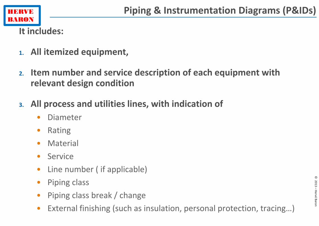
Piping & Instrumentation Diagrams (P&IDs)
It includes:
1. All itemized equipment,
2. Item number and service description of each equipment with relevant design condition
3. All process and utilities lines, with indication of
• Diameter
• Rating
• Material
• Service
• Line number ( if applicable)
• Piping class
• Piping class break / change
• External finishing (such as insulation, personal protection, tracing…)
HERVE
BARON
©2
01
3 –
He
rvé
Ba
ron
Piping & Instrumentation Diagrams (P&IDs)
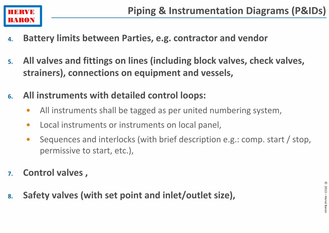
4. Battery limits between Parties, e.g. contractor and vendor
5. All valves and fittings on lines (including block valves, check valves,
strainers), connections on equipment and vessels,
6. All instruments with detailed control loops:
• All instruments shall be tagged as per united numbering system,
• Local instruments or instruments on local panel,
• Sequences and interlocks (with brief description e.g.: comp. start / stop,
permissive to start, etc.),
7. Control valves ,
8. Safety valves (with set point and inlet/outlet size),
HERVE
BARON
©2
01
3 –
He
rvé
Ba
ron
Piping & Instrumentation Diagrams (P&IDs)
9. Particular data or notes relevant to equipment/instruments
installation, such as:
• Max or mini length of piping (requirement regarding suction / discharge
piping straight length, etc.),
• Slope of piping
• Elevation of equipment
• Safe location requirement
• Control and monitoring signals for rotating equipments and electrical
motors (if applicable),
10. Item number and service description of each equipment with relevant
design condition
It shall be drawn-up according to ISA 6.12 requirements.
HERVE
BARON
©2
01
3 –
He
rvé
Ba
ron
� Various types of P&IDs
• Legend and Symbols
• Details and Typicals
• Process or Utility P&ID
• Distribution P&ID
• Interconnection P&ID
• Pumps auxiliary P&ID
• Package P&ID
Piping & Instrumentation Diagrams (P&IDs)
HERVE
BARON
©2
01
3 –
He
rvé
Ba
ron
P&IDs legend & symbols
HERVE
BARON
©2
01
3 –
He
rvé
Ba
ron
� Various types of P&IDs
• Legend and Symbols
− Identification and numbering system
− General Symbols
− Equipment symbols
− Piping Symbols
− Instrument Symbols
Piping & Instrumentation Diagrams (P&IDs)
HERVE
BARON
©2
01
3 –
He
rvé
Ba
ron
� Various types of P&IDs
• Legend and Symbols
− Identification and numbering system
− General Symbols
− Equipment symbols
− Piping Symbols
− Instrument Symbols
Piping & Instrumentation Diagrams (P&IDs)
HERVE
BARON
©2
01
3 –
He
rvé
Ba
ron
Identification and numbering system
HERVE
BARON
©2
01
3 –
He
rvé
Ba
ron
Identification and numbering system
HERVE
BARON
©2
01
3 –
He
rvé
Ba
ron
Identification and numbering system
HERVE
BARON
©2
01
3 –
He
rvé
Ba
ron
Identification and numbering system
HERVE
BARON
©2
01
3 –
He
rvé
Ba
ron
Piping & Instrumentation Diagrams (P&IDs)
Line
HERVE
BARON
©2
01
3 –
He
rvé
Ba
ron
Piping & Instrumentation Diagrams (P&IDs)
Line
HERVE
BARON
©2
01
3 –
He
rvé
Ba
ron
� Various types of P&IDs
• Legend and Symbols
− Identification and numbering system
− General Symbols
− Equipment symbols
− Piping Symbols
− Instrument Symbols
Piping & Instrumentation Diagrams (P&IDs)
HERVE
BARON
©2
01
3 –
He
rvé
Ba
ron
Piping & Instrumentation Diagrams (P&IDs)
HERVE
BARON
©2
01
3 –
He
rvé
Ba
ron
Piping & Instrumentation Diagrams (P&IDs)
Valve type,
position
HERVE
BARON
©2
01
3 –
He
rvé
Ba
ron
Piping & Instrumentation Diagrams (P&IDs)
Valve type,
position
HERVE
BARON
©2
01
3 –
He
rvé
Ba
ron
Piping & Instrumentation Diagrams (P&IDs)
Valve type,
position
HERVE
BARON
©2
01
3 –
He
rvé
Ba
ron
Piping & Instrumentation Diagrams (P&IDs)
Valve type,
position
HERVE
BARON
©2
01
3 –
He
rvé
Ba
ron
Piping & Instrumentation Diagrams (P&IDs)
Valve type,
position
HERVE
BARON
©2
01
3 –
He
rvé
Ba
ron
P&ID symbols
ANSI/ISA-5.1
What is the function of this valve?
How is it called?
HERVE
BARON
©2
01
3 –
He
rvé
Ba
ron
P&ID symbols
ANSI/ISA-5.1
What is the function of this valve? To control the downstream pressure
How is it called? Pressure reducing self regulated valve
HERVE
BARON
©2
01
3 –
He
rvé
Ba
ron
P&ID symbols
ANSI/ISA-5.1
What is the difference between these 2 valves?
HERVE
BARON
©2
01
3 –
He
rvé
Ba
ron
P&ID symbols
ANSI/ISA-5.1
What is the difference between these 2 valves? The 2nd one has external pressure tap
HERVE
BARON
©2
01
3 –
He
rvé
Ba
ron
P&ID symbols
ANSI/ISA-5.1
What do these symbols represent?
HERVE
BARON
©2
01
3 –
He
rvé
Ba
ron
P&ID symbols
ANSI/ISA-5.1
What do these symbols represent?
Rupture disk, Fail Open valve, Flow sight glass, Hydraulic signal
HERVE
BARON
©2
01
3 –
He
rvé
Ba
ron
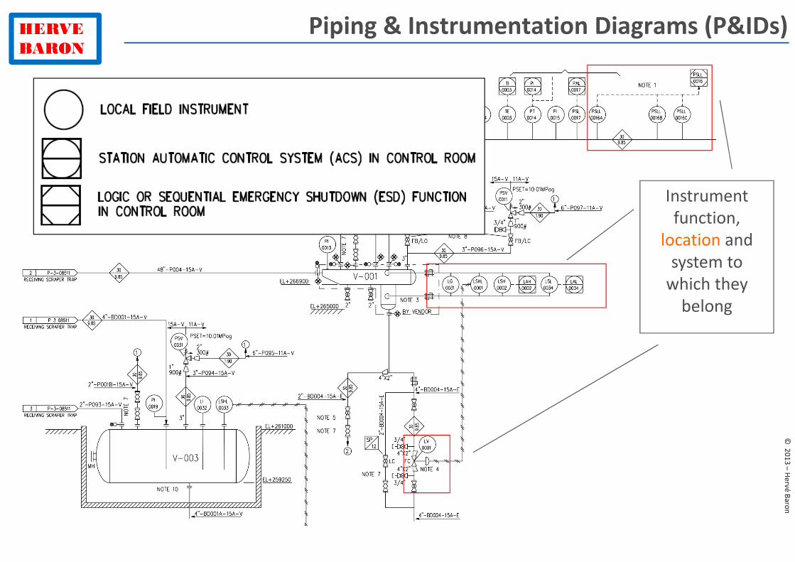
Piping & Instrumentation Diagrams (P&IDs)
Instrument
function,
location and
system to
which they
belong
HERVE
BARON
©2
01
3 –
He
rvé
Ba
ron
Piping & Instrumentation Diagrams (P&IDs)
Instrument
function,
location and
system to
which they
belong
HERVE
BARON
©2
01
3 –
He
rvé
Ba
ron
Piping & Instrumentation Diagrams (P&IDs)
Instrument
function,
location and
system to
which they
belong
HERVE
BARON
©2
01
3 –
He
rvé
Ba
ron
Piping & Instrumentation Diagrams (P&IDs)
Instrument
function,
location and
system to
which they
belong
HERVE
BARON
©2
01
3 –
He
rvé
Ba
ron
Piping & Instrumentation Diagrams (P&IDs)
Instrument
function,
location and
system to
which they
belong
HERVE
BARON
©2
01
3 –
He
rvé
Ba
ron
Piping & Instrumentation Diagrams (P&IDs)
Instrument
function,
location and
system to
which they
belong
HERVE
BARON
©2
01
3 –
He
rvé
Ba
ron
Piping & Instrumentation Diagrams (P&IDs)
Instrument
function,
location and
system to
which they
belong
HERVE
BARON
©2
01
3 –
He
rvé
Ba
ron
Piping & Instrumentation Diagrams (P&IDs)
Instrument
function,
location and
system to
which they
belong
HERVE
BARON
©2
01
3 –
He
rvé
Ba
ron
Piping & Instrumentation Diagrams (P&IDs)
Instrument
function,
location and
system to
which they
belong
HERVE
BARON
©2
01
3 –
He
rvé
Ba
ron
Piping & Instrumentation Diagrams (P&IDs)
Instrument
function,
location and
system to
which they
belong
HERVE
BARON
©2
01
3 –
He
rvé
Ba
ron
Piping & Instrumentation Diagrams (P&IDs)
Instrument
function,
location and
system to
which they
belong
HERVE
BARON
©2
01
3 –
He
rvé
Ba
ron
Piping & Instrumentation Diagrams (P&IDs)
Instrument
function,
location and
system to
which they
belong
HERVE
BARON
©2
01
3 –
He
rvé
Ba
ron
Piping & Instrumentation Diagrams (P&IDs)
What information is shown
in the red frame?
HERVE
BARON
©2
01
3 –
He
rvé
Ba
ron
Piping & Instrumentation Diagrams (P&IDs)
HERVE
BARON
©2
01
3 –
He
rvé
Ba
ron
Piping & Instrumentation Diagrams (P&IDs)
What information is shown
in the red frame?
HERVE
BARON
©2
01
3 –
He
rvé
Ba
ron
Piping & Instrumentation Diagrams (P&IDs)
What information is shown
in the red frame?
HERVE
BARON
©2
01
3 –
He
rvé
Ba
ron
Piping & Instrumentation Diagrams (P&IDs)
HERVE
BARON
©2
01
3 –
He
rvé
Ba
ron
Piping & Instrumentation Diagrams (P&IDs)
What information is shown
in the red bubble?
HERVE
BARON
©2
01
3 –
He
rvé
Ba
ron
Piping & Instrumentation Diagrams (P&IDs)
Line specification breaks
HERVE
BARON
©2
01
3 –
He
rvé
Ba
ron
� Various types of P&IDs
• Legend and Symbols
• Details and Typicals
• Process or Utility P&ID
• Distribution P&ID
• Interconnection P&ID
• Pumps auxiliary P&ID
• Package P&ID
Piping & Instrumentation Diagrams (P&IDs)
HERVE
BARON
©2
01
3 –
He
rvé
Ba
ron
� Various types of P&IDs
• Legend and Symbols
• Details and Typicals
− Piping Details
− Piping typical arrangements
− Instrument Details
− ON/OFF valves Typicals
− Motors Typicals
− Sample Connection Details
Piping & Instrumentation Diagrams (P&IDs)
HERVE
BARON
©2
01
3 –
He
rvé
Ba
ron
� Various types of P&IDs
• Legend and Symbols
• Details and Typicals
− Piping Details
− Piping typical arrangements
− Instrument Details
− ON/OFF valves Typicals
− Motors Typicals
− Sample Connection Details
Piping & Instrumentation Diagrams (P&IDs)
HERVE
BARON
©2
01
3 –
He
rvé
Ba
ron
Piping & Instrumentation Diagram
Piping Details
HERVE
BARON
©2
01
3 –
He
rvé
Ba
ron
� Various types of P&IDs
• Legend and Symbols
• Details and Typicals
− Piping Details
− Piping typical arrangements
− Instrument Details
− ON/OFF valves Typicals
− Motors Typicals
− Sample Connection Details
Piping & Instrumentation Diagrams (P&IDs)
HERVE
BARON
©2
01
3 –
He
rvé
Ba
ron
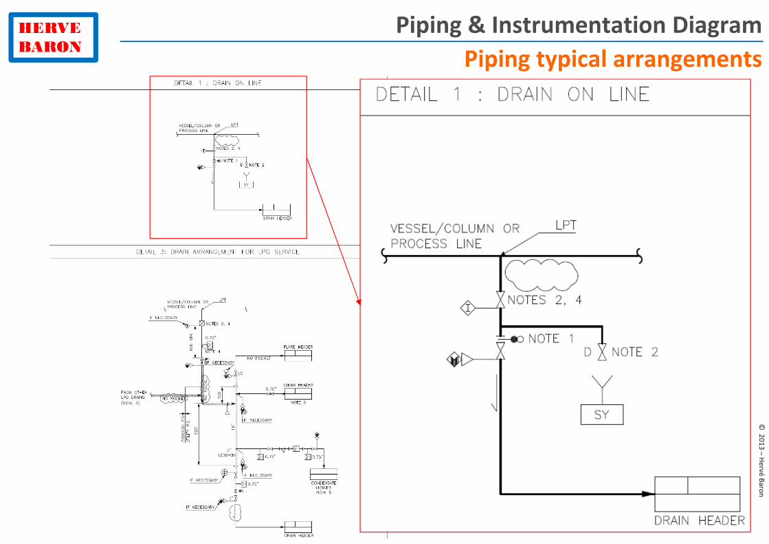
Piping & Instrumentation Diagram
Piping typical arrangements
HERVE
BARON
©2
01
3 –
He
rvé
Ba
ron
Piping & Instrumentation Diagram
What is the meaning of this
symbol, why is it in this position?
HERVE
BARON
©2
01
3 –
He
rvé
Ba
ron
Piping & Instrumentation Diagram
What is the meaning of this symbol,
why is it in this position?
Spacer/blind (also called “figure 8”,
spectacle/blind) in closed position.
It is in closed position to prevent
miss-operation of drain by
operator, such as draining before
depressurizing.
HERVE
BARON
©2
01
3 –
He
rvé
Ba
ron
P&ID arrangements
PSV
HERVE
BARON
©2
01
3 –
He
rvé
Ba
ron
P&ID arrangements
PSV
What do these indications mean?
HERVE
BARON
©2
01
3 –
He
rvé
Ba
ron
P&ID arrangements
PSV
What do these indications mean? That the line shall be sloped, without
pocket, to prevent accumulation of condensed gas.
HERVE
BARON
©2
01
3 –
He
rvé
Ba
ron
P&ID arrangements
PSV
What do these indications mean? That the line shall be sloped, without
pocket, to prevent accumulation of condensed gas.
This is an
example of
prescriptions
shown on the
P&ID by
Process to
Piping
discipline
HERVE
BARON
©2
01
3 –
He
rvé
Ba
ron
P&ID arrangements
PSV
On which other lines do you find similar requirements pertaining to the
routing of the line?
HERVE
BARON
©2
01
3 –
He
rvé
Ba
ron
P&ID arrangements
PSV
On which other lines do you find similar requirements pertaining to the
routing of the line? Gravity/Free draining line, line with no pocket, e.g.,
compressor suction line
HERVE
BARON
©2
01
3 –
He
rvé
Ba
ron
P&ID arrangements
Drains
What is the difference between these two drain typicals?
HERVE
BARON
©2
01
3 –
He
rvé
Ba
ron
P&ID arrangements
Drains
What is the difference between these two drain typicals? A minimum distance between
valves and heat tracing are specified on the right one, the type of valves is different
HERVE
BARON
©2
01
3 –
He
rvé
Ba
ron
P&ID arrangements
Drains
Why is there a minimum distance specified between the valves?
HERVE
BARON
©2
01
3 –
He
rvé
Ba
ron
P&ID arrangements
Drains
Why is there a minimum distance specified between the valves? To prevent freezing of the
second (downstream) valve due to flashing liquid in the first one. This would prevent the
closing of the second valve. This is what happened in the Feyzin refinery accident in France
and this minimum distance has been specified ever since.
HERVE
BARON
©2
01
3 –
He
rvé
Ba
ron
� Various types of P&IDs
• Legend and Symbols
• Details and Typicals
− Piping Details
− Piping typical arrangements
− Instrument Details
− ON/OFF valves Typicals
− Motors Typicals
− Sample Connection Details
Piping & Instrumentation Diagrams (P&IDs)
HERVE
BARON
©2
01
3 –
He
rvé
Ba
ron
Piping & Instrumentation Diagram
Depiction on
P&IDCorresponding details
HERVE
BARON
©2
01
3 –
He
rvé
Ba
ron
� Various types of P&IDs
• Legend and Symbols
• Details and Typicals
− Piping Details
− Piping Arrangements
− Instrument Details
− ON/OFF valves Typicals
− Motors Typicals
− Sample Connection Details
Piping & Instrumentation Diagrams (P&IDs)
HERVE
BARON
©2
01
3 –
He
rvé
Ba
ron
Piping & Instrumentation Diagram
ON/OFF valves Typicals
HERVE
BARON
©2
01
3 –
He
rvé
Ba
ron
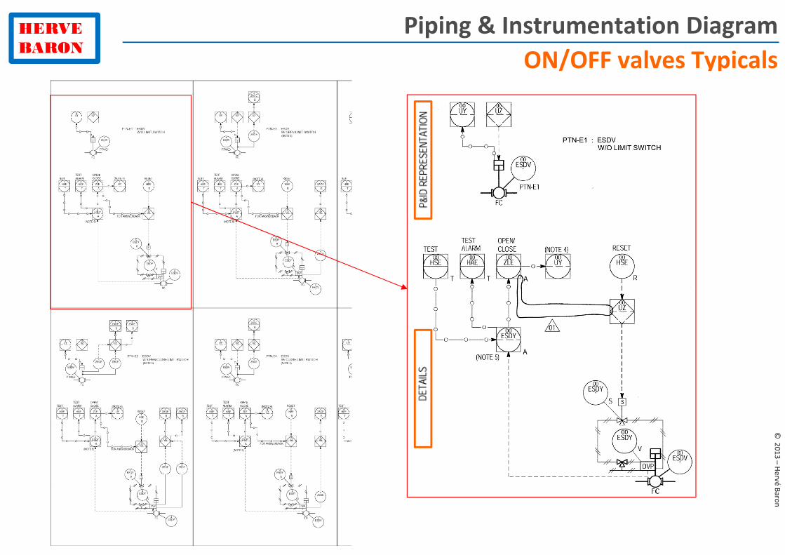
Piping & Instrumentation Diagram
ON/OFF valves Typicals
HERVE
BARON
©2
01
3 –
He
rvé
Ba
ron
� Various types of P&IDs
• Legend and Symbols
• Details and Typicals
− Piping Details
− Piping Arrangements
− Instrument Details
− ON/OFF valves Typicals
− Motors Typicals
− Sample Connection Details
Piping & Instrumentation Diagrams (P&IDs)
HERVE
BARON
©2
01
3 –
He
rvé
Ba
ron
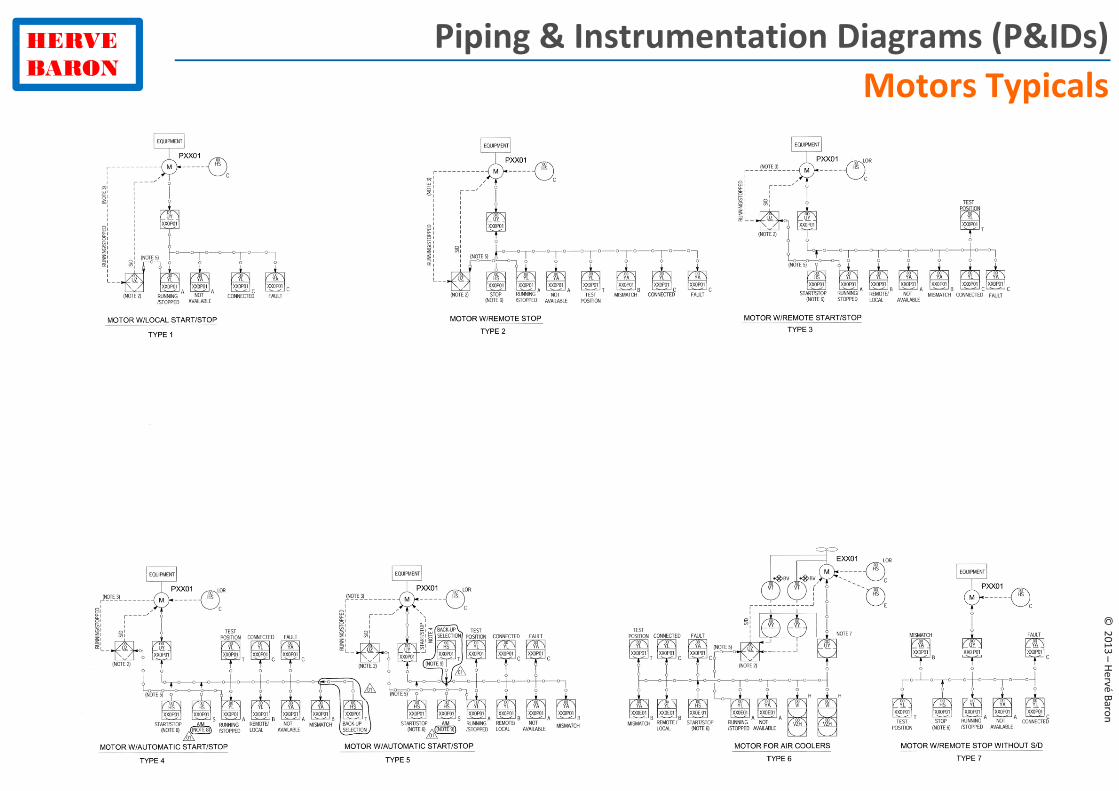
Piping & Instrumentation Diagrams (P&IDs)
Motors Typicals
HERVE
BARON
©2
01
3 –
He
rvé
Ba
ron
Piping & Instrumentation Diagrams (P&IDs)
Motors Typicals
HERVE
BARON
©2
01
3 –
He
rvé
Ba
ron
� Various types of P&IDs
• Legend and Symbols
• Details and Typicals
− Piping Details
− Piping typical arrangements
− Instrument Details
− ON/OFF valves Typicals
− Motors Typicals
− Sample Connection Details
Piping & Instrumentation Diagrams (P&IDs)
In your opinion, why such
standardization is made?
HERVE
BARON
©2
01
3 –
He
rvé
Ba
ron
� Various types of P&IDs
• Legend and Symbols
• Details and Typicals
− Piping Details
− Piping typical arrangements
− Instrument Details
− ON/OFF valves Typicals
− Motors Typicals
− Sample Connection Details
Piping & Instrumentation Diagrams (P&IDs)
Standardization is made
� For safety
� For quality
� For consistency for operator
� For cost (CAPEX: bulk order + OPEX: spare parts)
HERVE
BARON
©2
01
3 –
He
rvé
Ba
ron
� Various types of P&IDs
• Legend and Symbols
• Details and Typicals
• Process or Utility P&ID
• Distribution P&ID
• Interconnection P&ID
• Pumps auxiliary P&ID
• Package P&ID
Piping & Instrumentation Diagrams (P&IDs)
HERVE
BARON
©2
01
3 –
He
rvé
Ba
ron
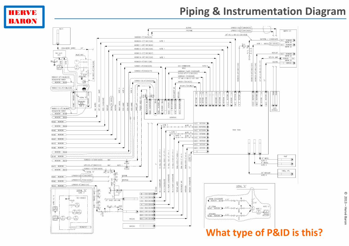
Piping & Instrumentation Diagram
What type of P&ID is this?
HERVE
BARON
©2
01
3 –
He
rvé
Ba
ron
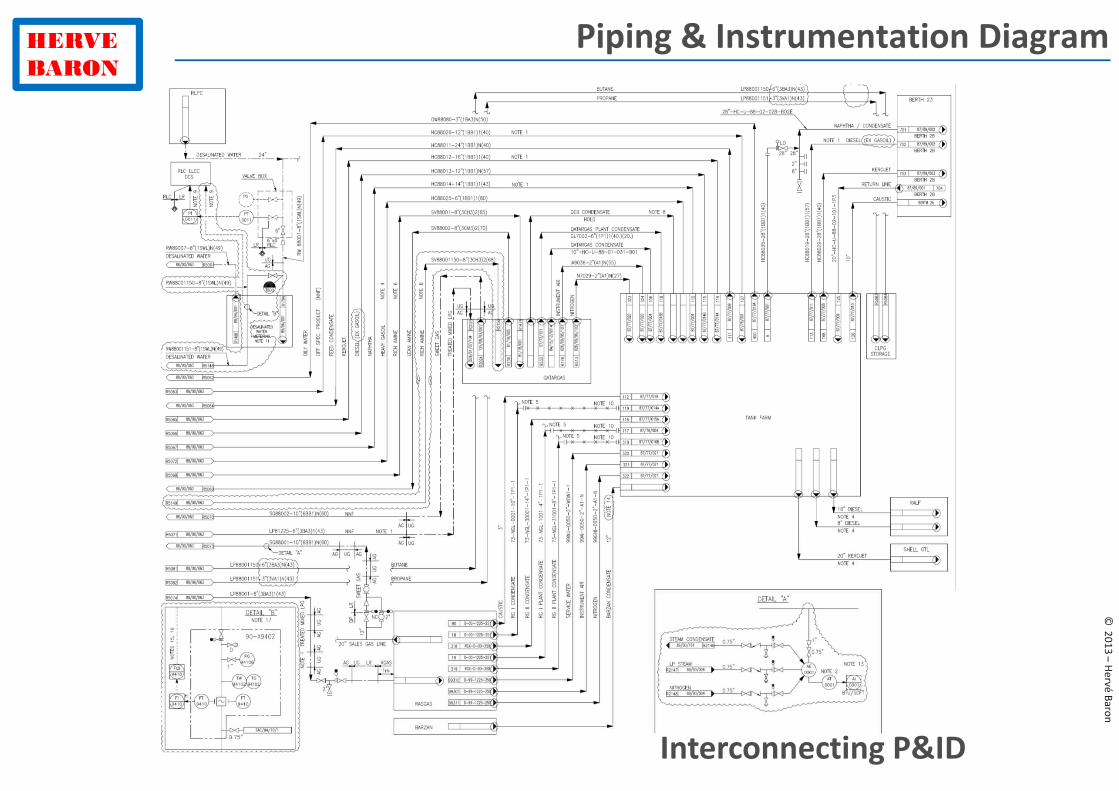
Piping & Instrumentation Diagram
Interconnecting P&ID
HERVE
BARON
©2
01
3 –
He
rvé
Ba
ron
Piping & Instrumentation Diagram
What type of P&ID is this?
HERVE
BARON
©2
01
3 –
He
rvé
Ba
ron
Piping & Instrumentation Diagram
Distribution P&ID
HERVE
BARON
©2
01
3 –
He
rvé
Ba
ron
Piping & Instrumentation Diagram
What type of P&ID is this:
•Process/Utility unit?
•Package?
•Auxiliary?
•Distribution?
•Interconnecting?
HERVE
BARON
©2
01
3 –
He
rvé
Ba
ron
Piping & Instrumentation Diagram
What type of P&ID is this:
•Process/Utility unit?
•Package?
•Auxiliary?
•Distribution?
•Interconnecting?
HERVE
BARON
©2
01
3 –
He
rvé
Ba
ron
Agenda
� The Process Diagrams
• The Block Flow Diagram (BFD)
• The Process Flow Diagram (PFD)
• The Piping & Instrumentation Diagram (P&ID)
�The various types of P&IDs
�The different revisions of the P&IDs
• Other Process diagrams
• Quiz
HERVE
BARON
©2
01
3 –
He
rvé
Ba
ron
P&ID work sequence
P&IDs are typically issued 3 times, as designed progresses
HERVE
BARON
©2
01
3 –
He
rvé
Ba
ron
P&ID work sequence
IFR IFD IFC
P&IDs are typically issued 3 times, as designed progresses
HERVE
BARON
©2
01
3 –
He
rvé
Ba
ron
P&ID work sequence
IFR IFD IFC
P&IDs are typically issued 3 times, as designed progresses
HERVE
BARON
©2
01
3 –
He
rvé
Ba
ron
P&ID work sequence
IFR IFD IFC
P&ID
Review
P&IDs are typically issued 3 times, as designed progresses
HERVE
BARON
©2
01
3 –
He
rvé
Ba
ron
P&ID work sequence
IFR IFD IFC
P&ID
ReviewHAZOP
P&IDs are typically issued 3 times, as designed progresses
HERVE
BARON
©2
01
3 –
He
rvé
Ba
ron
Quiz
Which revision of P&IDs has the following purpose/contents?
Purpose IFR IFD IFC
Collect Client comments
Perform PID review
Perform HAZOP
Perform Piping MTO for 1st Piping purchase
Freeze Control system I/O list
Issue Piping ISOs
Contents IFR IFD IFC
Comments from all disciplines
Comments from Piping, I&C disciplines
Finalized interfaces with eqt/package
Exercised Contract Option(s)
Size, number of PSVs and CVs
Diameter of process lines
Diameter of utility lines
HAZOP comments incorporated
Client comments incorporated
HERVE
BARON
©2
01
3 –
He
rvé
Ba
ron
Quiz
Which revision of P&IDs has the following purpose/contents?
Purpose IFR IFD IFC
Collect Client comments X
Perform PID review X
Perform HAZOP X
Perform Piping MTO for 1st Piping purchase X
Freeze Control system I/O list X
Issue Piping ISOs X
Contents IFR IFD IFC
Comments from all disciplines X
Comments from Piping, I&C disciplines X
Finalized interfaces with eqt/package X
Exercised Contract Option(s) X
Size, number of PSVs and CVs X
Diameter of process lines X
Diameter of utility lines X
HAZOP comments incorporated X
Client comments incorporated X
HERVE
BARON
For more information and…
to get on top of Engineering in hours, not years!
A unique synthesis and
reference manual
200 pages, 250 illustrations
To browse the book:
http://goo.gl/dfDrS
To order with a 30% discount:
http://goo.gl/J3TkE
HERVE
BARON
©2
01
3 –
He
rvé
Ba
ron
Agenda
� The Process Diagrams
• The Block Flow Diagram (BFD)
• The Process Flow Diagram (PFD)
• The Piping & Instrumentation Diagram (P&ID)
�The various types of P&IDs
�The different revisions of the P&IDs
• Other Process diagrams
• Quiz
HERVE
BARON
©2
01
3 –
He
rvé
Ba
ron
Other type of diagrams issue by Process
What diagram is this?
HERVE
BARON
©2
01
3 –
He
rvé
Ba
ron
Other type of diagrams issue by Process
What diagram is this?
The ESD simplified diagram (or sectionalisation diagram)
HERVE
BARON
©2
01
3 –
He
rvé
Ba
ron
Agenda
� The Process Diagrams
• The Block Flow Diagram (BFD)
• The Process Flow Diagram (PFD)
• The Piping & Instrumentation Diagram (P&ID)
�The various types of P&IDs
�The different revisions of the P&IDs
• Other Process diagrams
• Quiz
HERVE
BARON
©2
01
3 –
He
rvé
Ba
ron
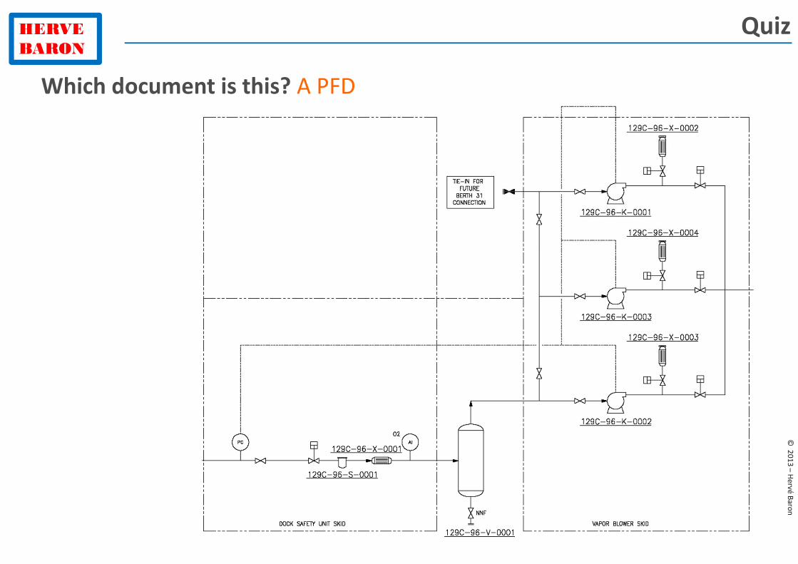
Quiz
Which document is this?
HERVE
BARON
©2
01
3 –
He
rvé
Ba
ron
Quiz
Which document is this? A PFD
HERVE
BARON
©2
01
3 –
He
rvé
Ba
ron
Quiz
Which process diagram is produced for each operating case?
Which Process Diagram shows the entire Plant?
The indication “NNF” (Normally Non Flowing) is shown on which
Process Diagram?
Which Process Diagram shows a Process (or utility) unit?
HERVE
BARON
©2
01
3 –
He
rvé
Ba
ron
Quiz
Which process diagram is produced for each operating case?
The PFD
Which Process Diagram shows the entire Plant?
The BFD
The indication “NNF” (Normally Non Flowing) is shown on which
Process Diagram?
PFD
Which Process Diagram shows a Process (or utility) unit?
PFD
HERVE
BARON
©2
01
3 –
He
rvé
Ba
ron
Quiz
Whose legend sheet is this?
HERVE
BARON
©2
01
3 –
He
rvé
Ba
ron
Quiz
That of PFDs, as, among other things, no line designation, no other instruments than
controllers
Whose legend sheet is this?
HERVE
BARON
©2
01
3 –
He
rvé
Ba
ron
Quiz
You just arrived at a new facility. What document will you ask to see
first to get an overall view of the Plant Process?
HERVE
BARON
©2
01
3 –
He
rvé
Ba
ron
Quiz
You just arrived at a new facility. What document will you ask to see
first to get an overall view of the Plant Process? The Block Flow Diagram
HERVE
BARON
©2
01
3 –
He
rvé
Ba
ron
http://www.toblog.fr/en/baron.html
You enjoyed this presentation?
Share my experience on other topics:
� Engineering
� Contract Management
� Project Control
Attend my classroom training
The list and schedule of coming sessions is on my blog at:
Going further