Weld ring gaskets Weld ring gaskets 06 95 We recommend weld ring gaskets for use in any place where a welded seal is necessary, due either to the danger of the medium or the danger presented by a loss of functionality, but where the connection also needs to be detachable to a certain degree. These gaskets are therefore described as being semi-de- tachable, as the welded sealing joint needs to be undone as well as the flange bolts. Weld ring gaskets are generally made of the same or a related material as the pipe or flange and are only used in pairs. The choice between the various profiles depends on the operating conditions of the weld ring gasket. The table shows the typical features of Profiles A21 to A25. The “attachment seam” is the connection of a welded half with the flange. The “attachment seam” can be located internally or externally. The “seal seam” is always the welding of both weld rings with one another. Typical features: Profile Internal "attachment seam" External “attachment seam” Capacity of radial Undo and re-weld Crevice corrosion Re-welding or differential expansion between weld ring and disassembly possible flange is avoided Usual Not possible Depending on the Easy to separate thickness of the wall with a 2 mm cutting wheel. of the torus, to a max. ∆ r ~ 5 mm Can be re-welded 2 to 4 times Possible to have Usual Depending on the Easy to separate additional attachment. thickness of the wall with a 2 mm cutting wheel. Intermittently welded of the torus, to a max. ∆ r ~ 5 mm Can be re-welded 2 to 4 times a) Only as an a) Usual setup Only low capacity Difficult to separate additional attachment. b) Only as an additional due to the small lip. Intermittently welded attachment aid. max. ∆ r ~ 0,5 mm Intermittently welded Can be re-welded b) if there is a danger 1 to 3 times of corrosion a) Only as an a) Usual setup Not really possible. With cutting wheel additional attachment. b) Only as an max.. ∆ r ~ 0,1 mm Separation loss 2 to 3 mm Intermittently welded. additional attachment respectively. aid. Intermittently b) if there is a danger welded Can be re-welded of corrosion 3 to 5 times Usual Not possible Flange Modest capacity With cutting wheel form M in accordance Depending on projection Separation loss 2 to 3 mm with DIN 2526 also max.. ∆ r ~ 0,3 mm respectively. Can be necessary re-welded 2 to 4 times Note: The suitability of the materials for welding (gasket to flange), the ability to weld (proper fitting) and the security of the weld- ing (expert layout and specifications) should be assessed and tested with regard to the local operating conditions by an expert welding engineer. The “attachment seams” and “seal seam” should be arranged so that they can withstand all load conditions. Weld rings with hollow lips in Profiles A24, A25 and A23 optimise the stress ratio in the seal seam. Weld rings with hollow lips are recommended for use when connecting com- ponents with different heat exchange properties. The advantage of weld ring gaskets in Profile A24 and A25 lies in their greater motion absorption. They are predomi- nantly used with heat exchangers with differing radial strain properties, e.g. as gaskets between channel flanges and tube plates. With the A24 gasket the weld seams are not accessible from the outside. However in many cases this is an advantage, particularly where creep corrosion is feared.
Transcript
Weld ring gaskets
Weld ring gaskets
06
95
We recommend weld ring gaskets for use in any place where
a welded seal is necessary, due either to the danger of the
medium or the danger presented by a loss of functionality,
but where the connection also needs to be detachable to a
certain degree.
These gaskets are therefore described as being semi-de-
tachable, as the welded sealing joint needs to be undone as
well as the flange bolts.
Weld ring gaskets are generally made of the same or a
related material as the pipe or flange and are only used in
pairs.
The choice between the various profiles depends on the
operating conditions of the weld ring gasket. The table shows
the typical features of Profiles A21 to A25. The “attachment
seam” is the connection of a welded half with the flange. The
“attachment seam” can be located internally or externally.
The “seal seam” is always the welding of both weld rings
with one another.
Typical features:
Profile Internal "attachment seam" External “attachment seam” Capacity of radial Undo and re-weldCrevice corrosion Re-welding or differential expansionbetween weld ring and disassembly possibleflange is avoided
Usual Not possible Depending on the Easy to separatethickness of the wall with a 2 mm cutting wheel.of the torus, to a max.∆ r ~ 5 mm Can be re-welded
2 to 4 times
Possible to have Usual Depending on the Easy to separateadditional attachment. thickness of the wall with a 2 mm cutting wheel.Intermittently welded of the torus, to a max.
∆ r ~ 5 mm Can be re-welded2 to 4 times
a) Only as an a) Usual setup Only low capacity Difficult to separateadditional attachment. b) Only as an additional due to the small lip.Intermittently welded attachment aid. max. ∆ r ~ 0,5 mm
Intermittently welded Can be re-weldedb) if there is a danger 1 to 3 times
of corrosion
a) Only as an a) Usual setup Not really possible. With cutting wheeladditional attachment. b) Only as an max.. ∆ r ~ 0,1 mm Separation loss 2 to 3 mmIntermittently welded. additional attachment respectively.
aid. Intermittentlyb) if there is a danger welded Can be re-welded
of corrosion 3 to 5 times
Usual Not possible Flange Modest capacity With cutting wheelform M in accordance Depending on projection Separation loss 2 to 3 mmwith DIN 2526 also max.. ∆ r ~ 0,3 mm respectively. Can benecessary re-welded 2 to 4 times
Note:
The suitability of the materials for welding (gasket to flange),
the ability to weld (proper fitting) and the security of the weld-
ing (expert layout and specifications) should be assessed
and tested with regard to the local operating conditions by an
expert welding engineer. The “attachment seams” and “seal
seam” should be arranged so that they can withstand all
load conditions.
Weld rings with hollow lips in Profiles A24, A25 and A23
optimise the stress ratio in the seal seam. Weld rings with
hollow lips are recommended for use when connecting com-
ponents with different heat exchange properties.
The advantage of weld ring gaskets in Profile A24 and A25
lies in their greater motion absorption. They are predomi-
nantly used with heat exchangers with differing radial strain
properties, e.g. as gaskets between channel flanges and
tube plates. With the A24 gasket the weld seams are not
accessible from the outside. However in many cases this is
an advantage, particularly where creep corrosion is feared.
Weld ring gaskets
Weld ring gaskets
06
96
In this case we recommend the following profiles: A24H,
A24K, A24KVR and A24N.
All weld ring gaskets can be combined with additional auxil-
iary gaskets. These can be useful for various different rea-
sons.
a) The pressure test should be carried out with an auxiliary
gasket without welding.
b) The start or run-up phase should be undertaken with the
auxiliary gasket, as it is likely to need to be opened sev-
eral times.
c) This application is generally in conjunction with the addi-
tional auxiliary gasket. The weld ring gasket is only welded
if the auxiliary gasket fails.
Weld ring gaskets should be fitted so that the weld ring halves
lie on top of each other, and parallel to each other and to the
flanges.
If weld ring gaskets are used with auxiliary gaskets, the
flange and bolt calculations must be carried out once for
the weld ring gasket with the seal diameter to the outer-
most seal seam and once for the auxiliary gasket.
With the use of auxiliary gaskets, a gap of 0.3 mm remains
between the weld ring gasket halves, depending on the de-
sign.
Note:
If there is a build-up of condensation during temperature
cycles, this can lead to an uncontrolled increase in pressure
in the torus. This can be avoided by inserting one or more
grooves (1.5 mm deep, 3 mm wide) into one of the ring
halves. Please specify the number of grooves when order-
ing.
Gasket profiles
Profile Cross-section
A23
A24
A24H
A24K
A25
A24KVR
Grooved profile gasket Profile B27A in a floating-type seal
A24NProfile A24H has a weld ring half with a convex sealing sur-
face. The radius conforms to the pressure, temperature and
the material involved. A galvanised coat can be useful.
Profile A24K has a weld ring half with a grooved profile, onto
which has been attached a layer approximately 0.5 mm thick
of either PTFE, graphite, silver or FA (fibre in accordance with
DIN 28091), depending on the operating conditions.
Profile A24KVR with male and female face joints and grooved
profile as shown in diagram. Depending on the operating
conditions, the layer for this gasket is either PTFE, graphite,
silver or fibre* at a thickness of approximately 0.5 mm.
Profile A24N has a groove in one weld ring half for the addi-
tion of a grooved profile gasket Profile B27A. For the materi-
als used in the gasket see the section “Grooved gaskets”.
The depth of the groove is less than the thickness of the
grooved profile gasket, so that a floating-type seal can be
guaranteed. The groove depth for the use of a grooved pro-
file gasket = 3,5-0,1 mm, the thickness of the grooved profile
gasket = 3,6+0,1 mm.
Weld ring gaskets
Weld ring gaskets
06
97
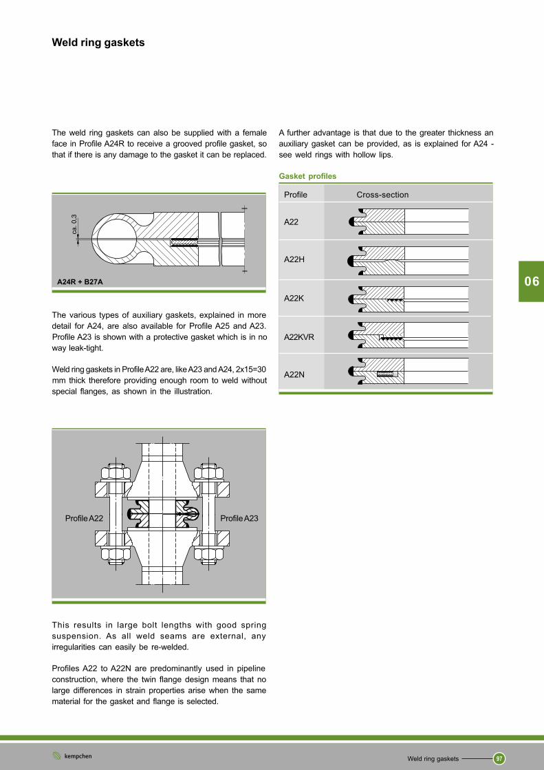
A further advantage is that due to the greater thickness an
auxiliary gasket can be provided, as is explained for A24 -
see weld rings with hollow lips.
Gasket profiles
Profile Cross-section
A22
A22H
A22K
A22KVR
A22N
The weld ring gaskets can also be supplied with a female
face in Profile A24R to receive a grooved profile gasket, so
that if there is any damage to the gasket it can be replaced.
The various types of auxiliary gaskets, explained in more
detail for A24, are also available for Profile A25 and A23.
Profile A23 is shown with a protective gasket which is in no
way leak-tight.
Weld ring gaskets in Profile A22 are, like A23 and A24, 2x15=30
mm thick therefore providing enough room to weld without
special flanges, as shown in the illustration.
This results in large bolt lengths with good spring
suspension. As all weld seams are external, any
irregularities can easily be re-welded.
Profiles A22 to A22N are predominantly used in pipeline
construction, where the twin flange design means that no
large differences in strain properties arise when the same
material for the gasket and flange is selected.
A24R + B27A
Profile A22 Profile A23
Weld ring gaskets
Weld ring gaskets
98
06
Profil A21
Membrane weld ring gasket Profile A21
Ordering example for a membrane weld ring gasket Profile
A21 with d1=115 mm internal diameter and d = 169 mm2external diameter, made of...
Gasket 115 x 169, DIN 2695, 1.5415
Each membrane weld ring gasket has two weld halves.
Conforms to DIN 2695 (PN 63 to PN 400) Model M
d23) at PN
DN d1 63 100 160 250 a. 320 400
80
100
125
150
200
250
300
350
400
to 3200 possible
Membrane rings in accordance with DIN 2695 are each 4
mm thick and should be made of the same material as the
flange due to the low absorption of radial strain differences.
These gaskets are firstly welded internally to the flange us-
ing an “attachment seam”, and once the flange has been
assembled a “seal seam” is made externally. Any errors
made when creating the internal welds can only be fixed
with great difficulty.
Gasket profile
Profile Cross-section
A21
First check if there is sufficient room to make the seal weld or
if bevelled flanges of the type Form M in accordance with DIN
2526 will be required.
The figure shows Profile A21K as assembled between
flanges of type Form M.
Membrane weld ring gaskets in Profile A21K are provided
with an additional grooved profile. The layers of PTFE, graph-
ite or silver are approximately 0.5 mm thick and should be
selected according to the operating conditions.
Dimensions in mm
90 143 149 149 153 153
115 169 176 176 179 179
142 206 213 213 216 216
165 243 248 248 248 248
214 305 315 315 315 315
264 360 370 370 370 -
310 420 430 430 - -
340 482 490 - - -
386 539 - - - -
1):
D
D
Weld ring gaskets
Weld ring gaskets
06
99
1) Specify materials when placing order.2) When bevelling the flanges the raised face should be
machined to this size (not required for DN150, 200, 350, 400).3) Aim for 15 mm membrane protrusion, but at least 10 mm
(maximum size: centring diameter less than 4 mm).
Profile A24
Weld ring gaskets Profile A24 for DIN flanges
Ordering example for a weld ring gasket, Profile A24, DN
500, PN 40, works standard 126, made of...1):
Weld ring gasket DN 500, PN 40, A24, 490 x 626, WN 126,
1.5415, s = ...*
Works standard 126
* size specified by client The wall thickness s is determinedaccording to pressure, temperature, material and motion to beabsorbed.
** In Profiles A24 to A24N the total width of the weld ring gasketmust be no less than (d
2-d
1) / 2 = 60 mm.
1) Specify material when placing order
PN
DN 16 25 40 63 100
d d d d d d d d d d1 2 1 2 1 2 1 2 1 2
250
300
350
400
500
600
700
800
900
1000
1200
1400
1600
1800
2000
Conforms to DIN 2695 (Class 150 to Class 2500) Model M
Size d32) for PN (DIN 2695) and Class
d2 In class
DN NPS d1 150 300 600 1500 2500
80 3 92 130 142 142 157 157
100 4 118 167 172 180 187 187
125 5 114 190 208 216 216 216
150 6 170 215 243 246 246 246
200 8 220 272 300 300 300 300
250 10 273 332 354 354 354 354
300 12 322 400 411 411 411 411
350 14 360 440 443 443 443 -
400 16 412 500 500 500 500 -
to 3200 possible
d32)
PN Class
DN NPS 63 - 400 150 300 600
80 3 123 116 122 122
100 4 149 146 150 -
125 5 186 172 180 -
150 6 218 196 - -
200 8 285 252 - -
250 10 340 308 - -
300 12 400 370 - -
350 14 460 - - -
400 16 519 - - -
900to
Dimensions in mm
Dimensions in mm
Dimensions in mm
Weld ring gaskets
Weld ring gaskets
06
100
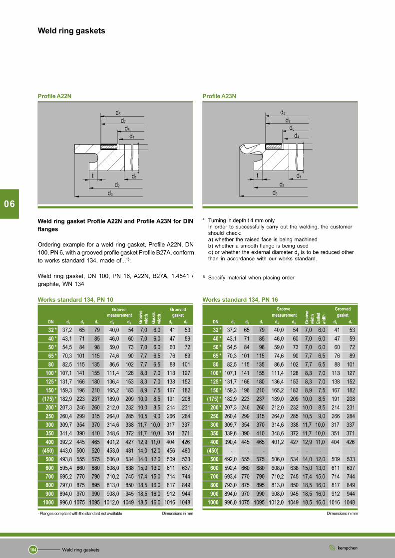
Profile A22 and A23 Weld ring gasket Profile A22* and Profile A23 in
accordance with DIN 2695 2002 for DIN flanges
Ordering example for a weld ring gasket, Profile A22, DN
100, PN 60, conforming to DIN 2695-2002, made of...1):
Weld ring gasket, DN 100, PN 160, A22, DIN 2695-2002,
1.5415
Each membrane weld ring gasket has two weld ring halves.
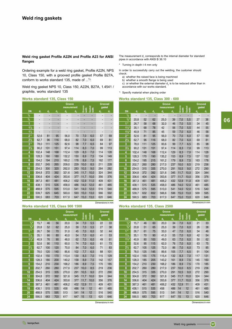
In order to successfully carry out the welding, the customer should checka) whether the raised face is being machinedb) whether a smooth flange is being usedc) or whether the external diameter d
3 is to be reduced other than in accordance with
our works standard.
1 ) Specify material when placing order2 ) At DN 10 and 15 only 4 mm* Model “S” conforms to DIN 2695-2002
Dimensions in mm
- Flanges compliant with the standard not available Dimensions in mm
Dimensions in accordance with DIN 2695-2002 for DIN flanges
Weld ring gasket Profile A22 and Profile A23 for DIN flanges
Ordering example for a weld ring gasket, Profile A22, DN
100, PN 160, conforming to works standard 110, made of...1):
Weld ring gasket, DN 100, PN 160, A22, works standard 110,
1.5415
Each membrane weld ring gasket has two weld ring halves.
In order to successfully carry out the welding, the customer should check:a) whether the raised face is being machinedb) whether a smooth flange is being usedc) or whether the external diameter d
3 is to be reduced other than in accordance with
our works standard.
1 ) Specify material when placing order2 ) At DN 10 and 15 only 4 mm
Weld ring gaskets
Weld ring gaskets
102
1) Specify material when placing order2) At NPS ½ and NPS ¾ only 4 mm
06
Weld ring gasket Profile A22* and A23 for ANSI flanges
Ordering example for a weld ring gasket, Profile A22, NPS 3,
Class 900, made of ...1):
Schweißdichtung A22, NPS 3, Class 900, WN 111, 1.5415
Profile A22 and A23
Dimensions in mm Dimensions in mm
Works standard 111 for ANSI flanges
Class
d d d d d1 2 3 2 3
150- 400- 1500- 150 300-DN NPS 300 900 2500 2500
15 ½ 15,7 14,0 6,4 29 45 29 45
20 ¾ 20,8 18,8 11,0 33 53 33 53
25 1 26,7 24,4 15,2 42 62 42 62
32 1 ¼ 35,1 32,5 22,8 52 72 55 75
40 1 ½ 40,9 38,1 27,9 60 80 64 84
50 2 52,6 49,3 38,2 75 95 83 103
65 2 ½ 62,7 58,9 45,0 96 116 96 116
80 3 78,0 73,7 58,4 105 125 118 138
100 4 102,4 97,3 80,1 148 168 148 168
125 5 128,3 122,2 103,2 160 180 177 197
150 6 154,2 146,3 124,4 185 205 207 227
200 8 202,7 193,8 174,6 240 260 261 281
250 10 254,5 247,6 222,3 295 315 315 335
300 12 304,8 298,4 273,1 372 392 372 392
350 14 336,6 330,2 304,8 404 424 404 424
400 16 387,3 381,0 355,6 461 481 461 481
450 18 438,1 431,8 406,4 525 545 525 545
500 20 488,9 482,6 457,2 575 595 575 595
600 24 590,5 584,2 558,8 683 703 683 703
* Model “S” conforms to DIN 2695-2002
In accordance with 2695-2002 for ANSI flanges
Class
d d d d d1 2 3 2 3
150- 400- 1500- 150 300-DN NPS 300 900 2500 2500
15 ½ 16 14 6 29 45 29 45
20 ¾ 21 19 11 33 53 33 53
25 1 27 24 15 42 62 42 62
32 1 ¼ 35 33 23 52 72 55 75
40 1 ½ 41 38 28 60 80 64 84
50 2 53 49 38 75 95 83 103
65 2 ½ 63 59 45 96 116 96 116
80 3 78 74 58 105 125 118 138
100 4 102 97 80 148 168 148 168
125 5 128 122 103 160 180 177 197
150 6 154 146 124 185 205 207 227
200 8 203 194 174 240 260 261 281
250 10 255 248 222 295 315 315 335
300 12 305 298 273 372 392 372 392
350 14 337 330 305 404 424 404 424
400 16 387 381 356 461 481 461 481
450 18 438 432 406 525 545 525 545
500 20 499 483 457 575 595 575 595
600 24 591 584 559 683 703 683 703
Weld ring gaskets
Weld ring gaskets
103
Each membrane weld ring gasket has two weld ring halves.
All measurements are recommendations and should be
checked by the client.
06
Weld ring gasket Profile A22 and Profile A23 for flanges in
accordance with ASME B16.47 Series A
Ordering example for a weld ring gasket, Profile A22, NPS
30, Class 150, made of...1):
Weld ring gasket A22, NPS 30, Class 150, WN 143, 1.5415
Works standard 143 for ASME B16.47 Series A flanges
* Turning in depth t 4 mm onlyIn order to successfully carry out the welding, the customershould check:a) whether the raised face is being machinedb) whether a smooth flange is being usedc) or whether the external diameter d