Weldability and Liquation Cracking Characteristics on Resistance-Spot-Welded High-Mn Austenitic Steel Dulal Chandra Saha,Yeong-Do Park Department of Advanced Materials Engineering, Graduate School of Engineering, Dong-Eui University, Busan 614-714, South Korea Email:[email protected], Phone: +82-10-6875-3118 (D.C. Saha) Email:[email protected], Phone: +82-10-6429-1860 (Y. D. Park) Abstract This paper describes the main issues associated with resistance spot welding (RSW) for high-Mn austenitic twinning-induced plasticity (TWIP) steels. Owing to rich chemistry which leads to complicated microstructure, and void formation in fusion zone (FZ) and eventually prone to early expulsion. Therefore, a dedication should be given to modify welding schedules. In this paper, a double pulse optimized schedules are adopted to maximize the weld lobe by improving the nugget sizes and suppressing expulsion. A double pulse schedule is optimized and comparisons are made with single pulse and three pulse ISO conditions. It is found that the nugget sizes are increased at about 15% which enlarged the tensile test failure load as well. Cross-tensile test (CTT) failure characteristics are observed in the sequences of: strain localization of both sheets, crack initiation at notch tip, crack followed fusion boundary, and finally ductile shear fracture along thickness direction. The welding imperfections are investigated using optical microscopy (OM) and scanning electron microscopy (SEM). It is already confirmed that resistance-spot-welded high-Mn steels have high susceptibility to heat-affected zone (HAZ) liquation crack; cracks are appeared in the HAZ when weld current is above 5.0 kA. Among the other factors, welding current is identified most influencing factors in liquation crack formation. This paper brought further information associated with crack formation. Keywords High-Mn austenitic steels; Resistance spot welding; Weldability; Optimization; HAZ liquation crack. Introduction Over the last decade, considerable effort has been devoted to develop high manganese (15-30%) twinning-induced plasticity steels for automotive applications [1-6]. Owing to their outstanding mechanical properties, non-magnetism, impact resistivity, corrosion resistance, TWIP steel considered as a unique candidates for automotive crash-worthy components [4-6]. Twinning is another important property of TWIP steels which enables mechanical deformation inside the grains under mechanical loading condition. The deformation mechanism, either dislocation glides or twins are determined by the factor of stacking fault energy (SFE) [7]. The twinning tendency can be predicted by SFE, high SFE in the ranges of (25 to 35 mJ/m 2 ) provides mechanical twinning inside the grains [4]. The main field of application of TWIP steel is automotive sector. A part form the microstructural investigation, welding and joining is intrinsic issue which needed to be evaluated prior to apply in automotives. RSW is the fundamental method of joining automotive parts; being said that every automotive contains around 2000-5000 spot welds. The spot welding is a materials joining process which is performed by using a combination of weld current, weld time, and electrode pressure. The sheets are placed under two pressurized electrode contact, and electric current is passed through upper electrode to lower electrode; the heat generates and fused metal at interface of two sheet where current experienced highest resistance during current flow. The joint integrity of spot welds must be ensured adequate safety to the passengers [8-10]. Through little beneficial information are obtained regarding microstructure and mechanical properties of laser welding TWIP steel investigated by Mujica et al. [11-13]. Due to limited information about the mechanical and microstructure analysis of spot welded high-Mn steels; materials still not widely accepted by automotive industries. The aim of the present work is to ensure the joint integrity of the welded part produced by RSW. Emphasize will be placed on parameter optimizations and weldability improvement (by enlarging nugget sizes). Here, a details discussion will be made on how optimized schedules enlarged the weld nugget and improved failure load. In addition, HAZ liquation cracking will be evaluated and discussion will be made on the effect of weld parameters on crack formation. Experiment Description Spot welding was performed on 980 MPa grades of cold rolled (1.4 mm) TWIP steels. The base materials composed of 0.6%C, 18% Mn, 1.5 % Al with minor alloying elements. The spot welding is assisted by ISO recommended standard [14], and optimized double pulse condition; details experiment schedules are presented on Table 1. The specimen dimensions and preparations for CTTs and tensile shear tests are followed by ISO standard [14]. 330
Transcript
Weldability and Liquation Cracking Characteristics on Resistance-Spot-Welded High-Mn Austenitic Steel
Dulal Chandra Saha,Yeong-Do Park Department of Advanced Materials Engineering, Graduate School of Engineering, Dong-Eui University, Busan 614-714,
South Korea Email:[email protected], Phone: +82-10-6875-3118 (D.C. Saha)
This paper describes the main issues associated with resistance spot welding (RSW) for high-Mn austenitic twinning-induced plasticity (TWIP) steels. Owing to rich chemistry which leads to complicated microstructure, and void formation in fusion zone (FZ) and eventually prone to early expulsion. Therefore, a dedication should be given to modify welding schedules. In this paper, a double pulse optimized schedules are adopted to maximize the weld lobe by improving the nugget sizes and suppressing expulsion. A double pulse schedule is optimized and comparisons are made with single pulse and three pulse ISO conditions. It is found that the nugget sizes are increased at about 15% which enlarged the tensile test failure load as well. Cross-tensile test (CTT) failure characteristics are observed in the sequences of: strain localization of both sheets, crack initiation at notch tip, crack followed fusion boundary, and finally ductile shear fracture along thickness direction. The welding imperfections are investigated using optical microscopy (OM) and scanning electron microscopy (SEM). It is already confirmed that resistance-spot-welded high-Mn steels have high susceptibility to heat-affected zone (HAZ) liquation crack; cracks are appeared in the HAZ when weld current is above 5.0 kA. Among the other factors, welding current is identified most influencing factors in liquation crack formation. This paper brought further information associated with crack formation.
Over the last decade, considerable effort has been devoted to develop high manganese (15-30%) twinning-induced plasticity steels for automotive applications [1-6]. Owing to their outstanding mechanical properties, non-magnetism, impact resistivity, corrosion resistance, TWIP steel considered as a unique candidates for automotive crash-worthy components [4-6]. Twinning is another important property of TWIP steels which enables mechanical deformation inside the grains under mechanical loading condition. The deformation mechanism, either dislocation glides or twins are determined by the factor
of stacking fault energy (SFE) [7]. The twinning tendency can be predicted by SFE, high SFE in the ranges of (25 to 35 mJ/m2) provides mechanical twinning inside the grains [4].The main field of application of TWIP steel is automotive sector. A part form the microstructural investigation, welding and joining is intrinsic issue which needed to be evaluated prior to apply in automotives. RSW is the fundamental method of joining automotive parts; being said that every automotive contains around 2000-5000 spot welds. The spot welding is amaterials joining process which is performed by using a combination of weld current, weld time, and electrode pressure. The sheets are placed under two pressurized electrode contact, and electric current is passed through upper electrode to lower electrode; the heat generates and fused metal at interface of two sheet where current experienced highest resistance during current flow. The joint integrity of spot welds must be ensured adequate safety to the passengers [8-10]. Through little beneficial information are obtained regarding microstructure and mechanical properties of laser welding TWIP steel investigated by Mujica et al. [11-13]. Due to limited information about the mechanical and microstructure analysis of spot welded high-Mn steels; materials still not widely accepted by automotive industries. The aim of the present work is to ensure the joint integrity of the welded part produced by RSW. Emphasize will be placed on parameter optimizations and weldability improvement (by enlarging nugget sizes). Here, a details discussion will be made on how optimized schedules enlarged the weld nugget and improved failure load. In addition, HAZ liquation cracking will be evaluated and discussion will be made on the effect of weld parameters on crack formation.
Experiment Description
Spot welding was performed on 980 MPa grades of cold rolled (1.4 mm) TWIP steels. The base materials composed of 0.6%C, 18% Mn, 1.5 % Al with minor alloying elements. The spot welding is assisted by ISO recommended standard [14],and optimized double pulse condition; details experiment schedules are presented on Table 1. The specimen dimensions and preparations for CTTs and tensile shear tests are followed by ISO standard [14].
330
Table 1: Welding schedules used in this investigation
Results and Discussion
Weldability evaluation and optimization The weldability evaluation is the predominant issue of a material to ensure applicability in industrial sectors. The suitable current ranges are determined at which nugget and
expulsion condition. Generally, owing to high chemical composition for AHSS which contributes to increase electric resistance; therefore the suitable current range shifts to the lower current side [15]. Therefore, optimization is the common practice employed by automotive industries to improve the weld quality in terms of maximizing the allowable weld current ranges. Several schemes are employed by researchers to maximize the weld parameters; Taguchi methods [16],regression modeling [17], neural network [18], etc. These types of parameter optimization schemes are sometimes inadequate or complex to get desired weld quality. Therefore, in this paper, authors attempted to use a simple and reliable double pulse method to optimize the welding schedule for TWIP steels. Fig. 1 shows the linear relationship between welding current and weld sizes. Throughout the welding current, the nugget and button diameters are found to superior for optimized condition. Higher nugget and button size provides higher CTT failure load as indicated in Fig. 3. One noticeable feature (Fig. 1) is that the nugget and button size differences between ISO and optimized schedules are more pronounce vicinity of expulsion condition. And this phenomenon is largely depends on heat input. In case of optimized schedule, first pulse is maintained at 6.0 kA and second pulse is varied from 4.0 to 8.0 kA. At lower current condition, total heat input (Q = I2×R×t) is higher in double pulse condition, which provides higher failure load. As the welding current increased, total heat inputs are going to be nearly equal (5.0 to 6.5 kA); hence failure load differences (between ISO and optimized schedule) declined as indicated in Fig. 3. During experiment, it is observed that the welding current higher than 7.0 kA always made expulsion; and all of cases expulsion is detected in first pulse of three pulses in ISO schedule (verified with dynamic resistance measurements). High heat input within short welding time (7.0 cycles), which might caused expulsion due to excessive heat generation at interface. By adopting double pulse schedule, the occurrence of expulsion in first pulse is suppressed, because first pulse weld current is kept at 6.0 kA, which is below the expulsion current in ISO condition; so, expulsion is ensured in second pulse. Second pulse is used to enlarge the nugget growth due to continuous heat input with longer weld time (14.0 cycles). Three parameters can be selected for optimized schedule; and
these are, for 1st pulse: weld current (I1) and weld time (t1); for 2nd pulse: weld time (t2). Priority should be given for selecting I1, and t1. Two main criteria can be suggested here to select appropriate 1st pulse. Firstly, 1st pulse current should be less than the expulsion current detected in single pulse experiment. In this experiment, using single pulse, the expulsion is confirmed at 6.5 kA (results are not shown here). Therefore, 1st pulse weld current is picked up 6.0 kA; and it is certainly sure that expulsion would not be occurred in 1st pulse. Secondly, t1 should be chosen such a way that with combination of I1 and t1, nugget diameter would be about
Figure 1: Weld growth curves for TWIP steels using ISO and optimized conditions; a) based on button diameter, and b)
based on nugget diameter.
As 2nd pulse is helping the nugget (which is formed in 1st
pulse) to re-melt and expand more; therefore, the heat input in 2nd pulse must be superior to the former pulse. In 2nd pulse, welding current (I2) is variable and only parameter to be
Schedule EF (kN)Schedule (Cycle, 60 Hz)
Tip DiaPulses Current (I1) Weld (t1) Cooling-1 Current (I2) Weld (t2) Cooling-2 Current (I3)
Weld (t3)
ISO [14] 4.5 kN 3 4.0 8.0 kA 7.0 2.0 4.0 8.0 kA 7.0 2.0 4.0 8.0 kA 7.0 8.0 mm
Optimized 4.5 kN 2 6.0 kA 7.0 4.0 4.0 8.0 kA 14.0 - - - 8.0 mm
331
selected is welding time (t2); which can be chosen from prescribed ranges. One thing should be noted here that the value of t2 should be around two times of t1; and these longer weld time would permit uninterrupted heat input throughout the welds.
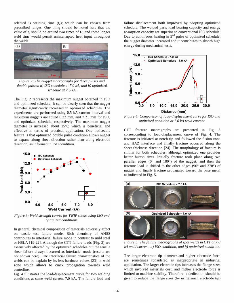
Figure 2: The nugget macrographs for three pulses and
double pulses; a) ISO schedule at 7.0 kA, and b) optimized schedule at 7.5 kA.
The Fig. 2 represents the maximum nugget obtained in ISO and optimized schedule. It can be clearly seen that the nugget diameter significantly increased in optimized schedules. The experiments are performed using 0.5 kA current interval and maximum nuggets are found 6.22 mm, and 7.21 mm for ISO, and optimized schedule, respectively. The maximum nugget diameter is increased about 15%; which is beneficial and effective in terms of practical application. One noticeable feature is that optimized double pulse condition allows nugget to expand along sheet direction rather than along electrode direction; as it formed in ISO condition.
Figure 3: Weld strength curves for TWIP steels using ISO and optimized conditions.
In general, chemical composition of materials adversely affect on tensile test failure mode. Rich chemistry of AHSS contributes to interfacial failure mode in contrast to mild steel or HSLA [19-22]. Although the CTT failure loads (Fig. 3) are extensively affected by the optimized schedules but the tensile shear failure always occurred as interfacial mode (results are not shown here). The interfacial failure characteristics of the welds can be explain by its less hardness values [23] in weld zone which allows to crack propagation towards weld centerline. Fig. 4 illustrates the load-displacement curve for two welding conditions at same weld current 7.0 kA. The failure load and
failure displacement both improved by adopting optimized schedule. The welded parts load bearing capacity and energy absorption capacity are superior to conventional ISO schedule. Due to continuous heating in 2nd pulse of optimized schedule, the nugget diameter increased and it contributes to absorb high energy during mechanical tests.
Figure 4: Comparison of load-displacement curve for ISO and optimized condition at 7.0 kA weld current.
CTT fracture macrographs are presented in Fig. 5 corresponding to load-displacement curve of Fig. 4. The fracture is initiated at notch tip and followed the fusion zone and HAZ interface and finally fracture occurred along thesheet thickness direction [24]. The morphology of fracture issimilar for both schedules; although optimized one provides better button sizes. Initially fracture took place along two parallel edges (0° and 180°) of the nugget; and then the fracture load is shifted to the other edges (90° and 270°) of nugget and finally fracture propagated toward the base metal as indicated in Fig. 5.
Figure 5: The failure macrographs of spot welds in CTT at 7.0 kA weld current, a) ISO condition, and b) optimized condition.
The larger electrode tip diameter and higher electrode force are sometimes considered as inappropriate in industrial application. The larger electrode tips increases the flange sizes which involved materials cost; and higher electrode force is limited to machine stability. Therefore, a dedication should be given to reduce the flange sizes (by using small electrode tip)
(a) (b)
332
and cut down the electrode force to ensure proper stability of the welder. Therefore, small electrode tip and lower electrode force both are considered to generalize the effect of double pulse condition on nugget diameter. The welds are performed by using 6.0 mm electrode tip and 3.50 kN electrode force. The effect of optimized schedule also prominent here; about 15% nugget diameter improved which is resembled with previous optimized results (explained earlier). Therefore, it can be noted here that the optimization procedure proposed in this experiment is beneficial compared to single pulse and three pulses (ISO) condition. The nugget size improvement is not affected by electrode tip diameters and electrode forces.
Figure 6: The nugget macrographs for single pulse and double pulse; a) at single pulse 20 cycles, 6.0 kA (3.50 kN),
and d) at double pulse, I1=6.0 kA, t1=6.0cy, ct=2.0cy, I2=7.0 kA and t2=12.0cy (3.50 kN).
Characteristics of HAZ liquation crack There are several welding imperfections which are detected in welded nuggets; between them, voids, shrinkage cavities, and HAZ liquation cracks are major welding defects [23]. The microstructural investigation of cracks morphologies are carried out by using optical microscope and scanning electron microscope (SEM); and microstructure is shown in Fig. 7.
Figure 7: The morphology and appearance of the cracks in high-Mn steel welds; a) optical macrograph of nugget cross-section showing shrinkage cavity and HAZ liquation crack, b)
SEM image of shrinkage cavity, c) optical micrographs of liquation crack in HAZ, and d) SEM image of liquation crack
with substantial liquid film.
In this research work, authors would like to focus on liquation cracks characteristics. The HAZ liquation crack is a high temperature crack which appeared in the HAZ adjacent to the weld nugget with substantial liquid films along the grain boundary [25]. Liquation of the grains either occurs by the secondary phase or low-melting point impurities [10]. Cracks are located in HAZ, and it propagated along the base metal (BM); cracks are formed along the sheet direction rather than in electrode direction (sheet thickness) [23]. Most of the cases, cracks are present beside the notch tips (Fig. 7) with a wide base and narrow tip. Similar types of cracks had characterized and reported for aluminum and magnesium alloys [10, 26, 27].
The formations of cracks are strongly dependent on weld current; crack opening width, lengths both increased with weld current [23]. The crack formation and propagations are also affected by the other major welding parameters like, welding time, electrode force, electrode geometry etc. Among the other parameters, weld current is the most influencing parameter for crack formation. In this experiment the minimum weld current is determined 5.0 kA for ISO schedule (Table 1); which is required to initiate crack in HAZ area. By increasing heat input which helped to liquate the grain boundaries more. The liquid films weakened the grain boundaries and it have enough strength to sustain tensile strength developed in HAZ area during RSW; and the crack formed. The cracks are healed with liquid metal and liquid films; and even after the liquid films are detected in cracking zone when it solidified into the room temperature (Fig. 7(d)) [23]. Fig. 8 illustrates the HAZ and PMZ in spot welded samples; the PMZ shows the substantial grain liquation. The liquation of the grains can be occurred either by low melting point eutectics, or by melting of secondary phases [28]. The average grain sizes of the HAZ (Fig. 8) is 3-4 times higher than the average grain size of the BM [23]; therefore, less liquid films is required to cover the entire grain boundaries and it increases the crack susceptibility as reported by Lippold et al. [29]. The crack formation is associated with solid materials flow during heating. The solid materials flow is detected on cracked nugget. The Fig. 9(b) indicated the solid materials flow along with cracking; no materials flow as well as no crack formation is observed in Fig. 9(a). Solid materials flow formed a blunt notch which provides large sheet separation and favors to crack formation as stated by Zhang et al. [10, 23, 26].
Figure 8: The optical micrographs of a) HAZ and b) grain boundary liquation in PMZ.
Shrinkage cavity
HAZ Liquation Crack
(a) (b)Grain boundary liquation
(a) (b)
(c) (d) Grain liquation
Liquid films
(a) (b)
333
Figure 9: The interface notch area of the spot welded sample; a) at weld current at4.5 kA; and at weld current at 6.0kA.
The liquation crack is almost unavoidable, when nugget diameter reached at a certain shape then crack initiates in HAZ. The tendency of liquation crack can be minimized by modifying the BM composition which changed the solidification mode from A type to FA type, i.e, solidification changed from primary austenitic mode to primary ferrite dendrites with an interdendritic layer of austenite. The formation of grain boundary ferrite would reduce the cracking susceptibility. Welding power (AC or MFDC), weld current waveform (single pulse or multi-impulse) has no effect on crack suppression. Either single pulse or two pulses or three pulses i.e., all of the pulsed condition, crack appeared on HAZ at a certain heat input. Even dissimilar welding can not help to suppress crack. Fig.10 shows the dissimilar weld microstructure, which indicates the cracks only at the side of high-Mn (TWIP) steel. The preliminary experiment results shows that there is less significant effect of liquation crack on CTT and TST failure load. The details investigation will be performed and will be reported in separate paper. Several authors also concluded the insignificant effect of this type of crack on weld performance [10, 26, 27].
Figure 10: The dissimilar spot welded nugget cross-section of 980TWIP (1.4t) and 980DP (1.4t) steels (weld current 6.0kA,
20 cycles, single pulse).
Conclusions
This research provided a valuable insight about weldability, mechanical properties, and crack formation behavior for resistance spot welded high-Mn austenitic steels. The major conclusions can be summarized as follows; 1. A double pulse schedule is optimized and proposed to
widen the weld lobe for high-Mn steels. By employing optimized schedules, about 15% nugget diameter is increased. Not only nugget diameter but also the load bearing capacity in CTT also increased.
2. Optimized schedule is much more beneficial compared to conventional single pulse and ISO three pulse schedules. The effect of optimized schedule is independent of electrode force and electrode tip diameter; i.e. the schedule is applicable for high electrode force and larger electrode tip diameter condition as well as low electrode force and small electrode tip diameter condition.
3. The welded part has high tendency to form crack; cracksare appeared in the HAZ adjacent to the weld nugget when weld current reached at a certain level. The crack formation, and propagation is influenced by weld current, weld time, and electrode force.
4. Crack formation is almost unavoidable and it is not affected by welding power, weld current waveform, and dissimilar materials combinations. However, this kind of crack has less significant effect on weld performance.
References
[1]Development of a New Fe-Mn-C Austenitic Steel for
Rev Metall Cah Inf Tech, Vol. 103 (2006), pp. 293-302.
[2]Strength Fe-Mn-(Al, Si) TRIP/TWIP Steels Development - Properties - Int J Plasticity, Vol. 16 (2000), pp. 1391-1409.
[3] -Strength and High-J Mater Sci
Technol, Vol. 21, No. 4 (2005), pp. 451-454.[4] and
Corrosion Behavior of High-Dissertation, Department of Mechanical Engineering, Faculty of Technology, University of Oulu, FIN-90014University of Oulu, Finland, 2007.
[5]Strength Trend Met & Mater Eng, Vol. 19, No. 2 (2006).
[6] -ductile And High-Strength Manganese- ISIJ Int, Vol. 43, (2003), pp. 438 446.
[7] Oh B.W., Cho S.J., Kim Y.G., Kim Y.P., Kim W.S., ct of Aluminium on Deformation Mode
and Mechanical Properties of Austenitic Fe-Mn-Cr-Al-CMater Sci Eng A, Vol. 197, (1995), pp. 147-156.
No materials flow
No cracks
Materials flow
Crack in HAZ
(a) (b)
TWIP
DP
(a)
(b) (c)
334
[8]J Mater Sci,
Vol. 31, (1996), pp. 5443-5449.[9] Pouranvari M., Mousavizadeh S.M., Marashi S.P.H.,
Size and Failure Mode on Mechanical Performance of Dissimilar Resistance Spot Welds of AISI 1008 Low Carbon Steel and DP600 Mater Des, Vol. 32 (2010), pp. 1390-1398.
[10] Zhang H., Senkara J., Resistance Welding Fundamentals and Applications, CRC Press/Taylor & Francis Group, (Boca Raton, London, New York, 2006), ISBN 0-8493-2346-0.
[22] Naït-Behavior of Advanced High-Strength Steel Resistance
on, Sheet Metal Welding Conf. XIII, Livonia, MI, May 14-16, 2008.
[23] Saha D.C., Han S., Chin K.G., Choi I.D., Park Y.D.,
Resistance-Spot-Welded High-Mn Steel in Automotive Steel Res Int, Vol. 83, No. 4, (2012), pp.
352-357. [24]
Resistance Spot Welded Low Carbon Steel in Tensile-Shear and Coach-Association of Metallurgical Engineers of Serbia (AMES), Scientific Paper, Metalurgija-Journal of Metallurgy, Vol. 15, No. 3, (2009), pp. 149-157.
[25] -Affected
Dissertation, The Ohio State University, 1991. [26]
JManuf Sci Eng, Vol. 124, (2002), pp. 79-85.
[27] Luo H., Hao C., Zhang J., Gan J., Chen H., Zhang H., m
Weld J, Vol. 91, December 2011, pp. 249-s-257-s.
[28]Metallurgy and Weldability of Nickel-Hoboken New Jersey: John Wiley & Sons, Inc; 2009, p. 118-128.
[29] Shi S., Lippold J.C., Service-Exposed, Heat-Resisting Alloys-Austenitic Stainless Steel Castings: HP45Nb and 20- Proc 7th
International Conf on Trends in Welding Research,Callaway Gardens Resort, Pine Mountain, Georgia, USA, May 16-20, 2005, pp 293-298.


![This document is published in - COnnecting REpositoriesabilityand weldability,and remarkablestress corrosion cracking resistance[4],Al–Zn–Mg–Cu alloys have long been regarded](https://static.documents.pub/doc/80x56/60a1aac62649ca0c377043db/this-document-is-published-in-connecting-repositories-abilityand-weldabilityand.jpg)


