Page 1
..
..
(
WELDED INTERIOR BEAM COLUMN CONNECTIONS
A report on investigations carried out by
J Q Do GRAHAM
AQ NQ SHERBOURNE
RQ No KHABBAZ
under the direction of
Co. Do JENSEN
This project has been sponsored by the American
Institute of Steel Construction.
Fritz Engineering Laboratory
LEHIGH UNIVERSITY
Bethlehem, Pennsylvania.
1959
Fritz Laboratory Report No. 233.15
Page 2
1.
TABLE OF CONTENTS
WELDED INTERIOR BEAM COLUMN CONNECTIONSf:' .~
PART. A.
SYM¥OLS
SYN9PSIS
OPT~INE OF INVESTIGATION
TEST PROGRAM'I
1. Two=way Connection Testsi
4
6
9
11
11
19
233. pimulated Connection Tests
3 0 1 Tests to Determine Column Web
Buckling Criterion 23
3.2 Tests to Determine Connection Tension 25
2 0 four-way Connection Tests
•
o
Criterion
3.3 Eccentric Stiffener Tests 27
DISCUSSION OF TEST RESULTS\ - .
1. ponnection Requirements
2. two-way Connection Tests
30 Four=way Connection Tests!
4. ~ffect of Axial Load
5. 9orrelation of Tests
Dol Tests to Determine Compression
Criterion
29
29
29
31
32
32
32
50 2 Tests to Determine Tension Criterion 33
503 Eccentric Stiffener Tests 34--
Page 3
TABLE OF CONTENTS (contU~)
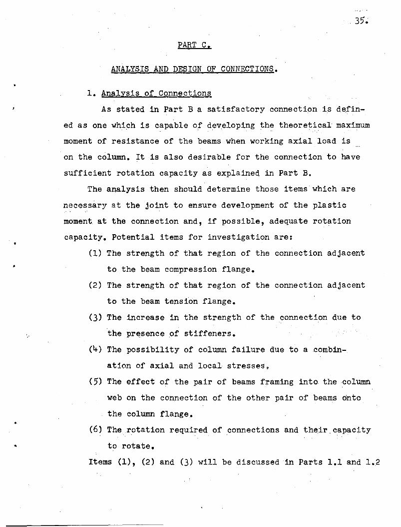
PART 0 C. ANALYSIS AND DESIGN OF CONNECTIONS
1. Analysis of Connections
1.1 Analysis of Compression Region of
Connection
1.2 Analysis of Tension Region of
Connection
. PagQ
35
35
36
39
2.
APPENDIX
1.3 Relative strengths of Tension and
Compression Regions of Connection 41
2. Comparison of Test Results with Analysis 42
2.1 Compression Region of Connection 42
2.2 Tension Region of Connection 47
30 Limitations of this Investigation 50
4. Advocated Design Methods 50
40 1 Connection in which no Stiffening 50
is Required
. 4.2 Connection in which Stiffening is
Required in Compression Region Only 51
4.3 Connection in which Stiffening is
Needed in Both Tension and Compression
Regions· 52
4.4 Eccentric Stiffening 53
1 0 Theoretical Analysis
1.1 Limiting Slenderness of Stiffeners
1 .. 2 Rotation of Connections
103 Elastic Distribution of Stress on
Column ikU Line 56
Page 4
,"
,-
TABLE OF CONTENTS (ContUd)
l.~ Probable Inelastic Distribution of
Stress on Column iku Line
1.5 Alternative Design Formulas for Com=
pression Region of Connections
1.51 Plastic Analysis
1.52 Modified Plastic Analysis
1.6 Analysis of Tension Region of
Connection
2. Appendix to Two=way Tests
2.1 Summary of Coupon Tests
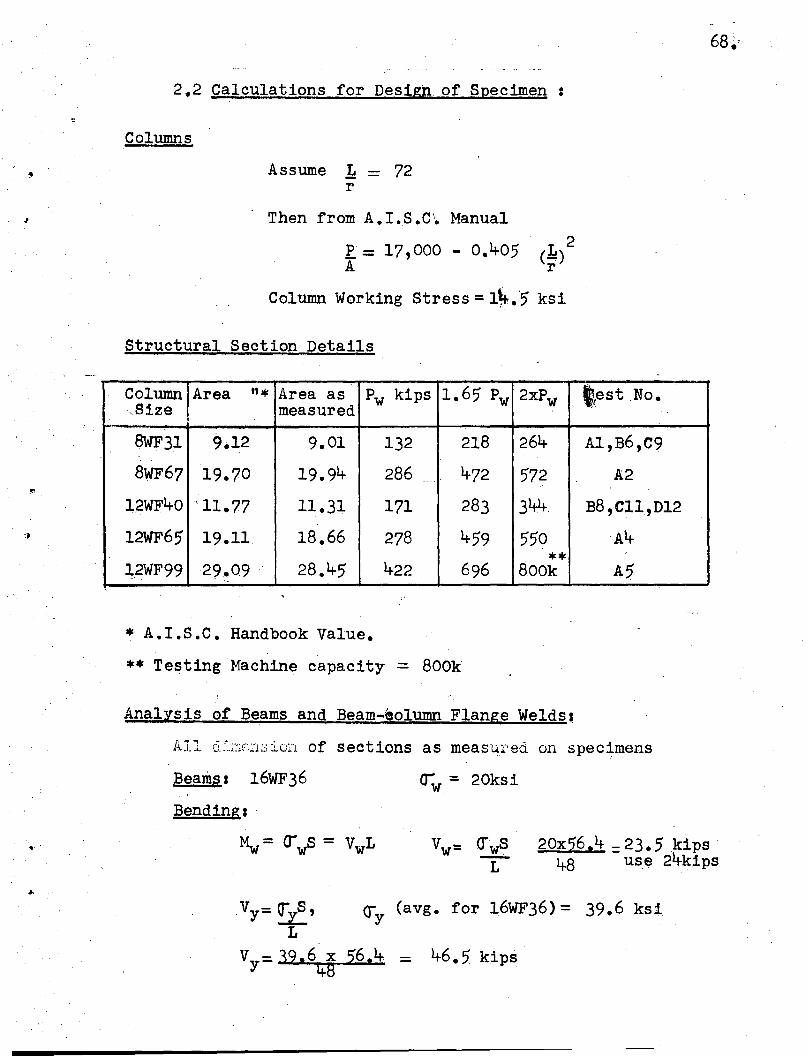
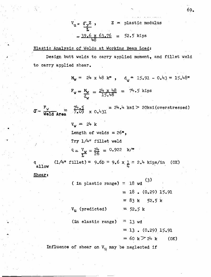
2.2 Calculations for Design of Specimens
2.3 Material Dimensions and Properties
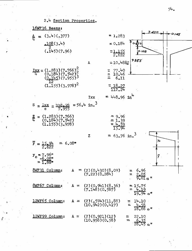
2.~ Section Properties
3. Appendix to Four=way Tests
3.1 Summary of Coupon Tests
3.2 Calculations for Design of Specimens-,
3.3 Material Dimensions and Properties
FIGURES
BIBLIOGRAPHY
ACKNOWLEDGEMENTS
58
59
5960
6366
66
68
72
74
75
75
76
78
3.
Page 5
SYMBOLS
w
k
" ~ t c
dc
m
Column Web Thickness
Column 'k l Distance
Column Flange Thickness
Column Depth
Distance between Fillet Extremeties of
Column
b Beam Flange Width
t Beam Flange Thickness
t' Beam Web Thickness
d Beam Depth
Ab Beam Cross Sectional Area
s Stiffener Thickness,
b' Stiffener Width
Theoretical Maximum or 'Plastic' Moment
of the Beam
My Moment to Cause First Yielding of the Beam
Mw Beam Working MQment
Vu Load (also the shear) on the Test Beam to
Produce Mp
Vy Load (also the shear) on the Test Beam to
Produce My
VwLoad (also the shear) on the Test Beam to
Produce MwPw Column Working Load
1/
Deflection of Loading Point of Beam "at Vydy
S Elastic Section Modulus/
/
Z Plastic Section Modulus
Page 6
SYMBOLS (ContRd)
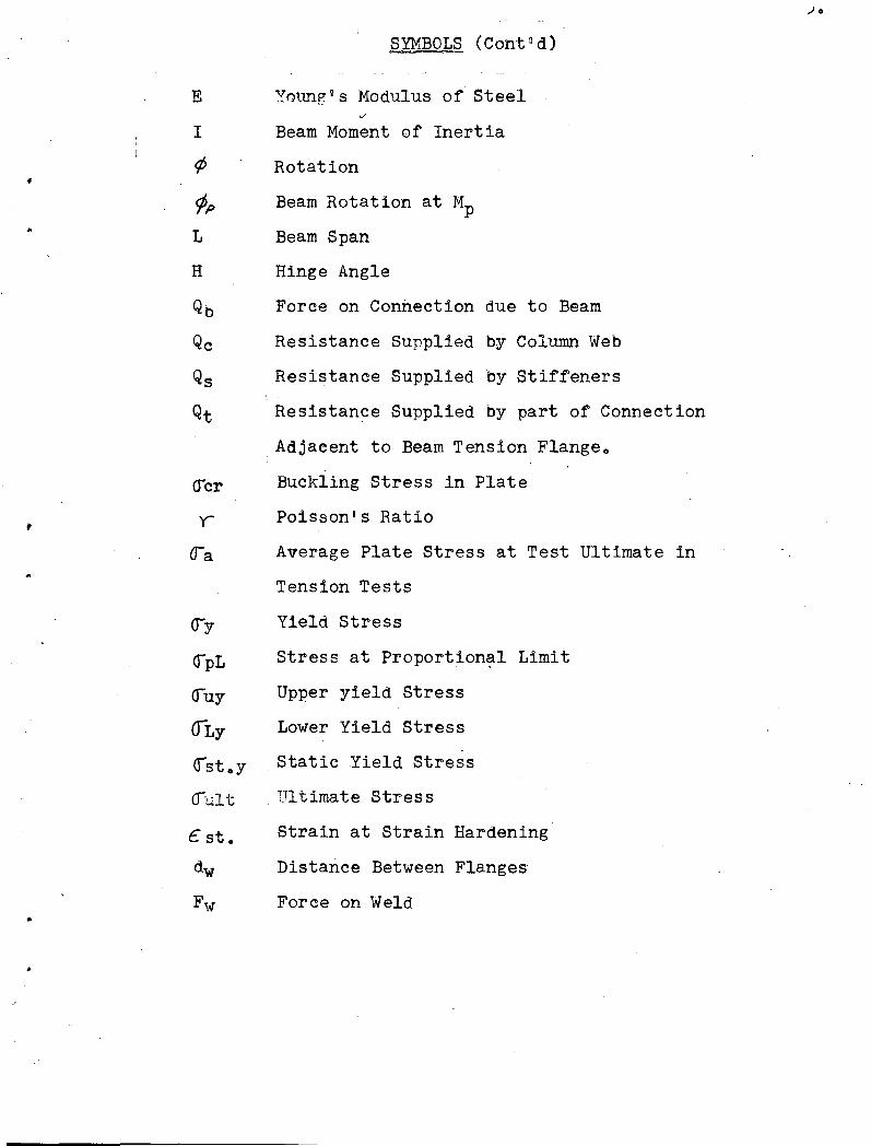
E Young 9 s Modulus of Steel
I Beam Moment of Inertia
1> Rotation
¢p Beam Rotation at Mp
L Beam Span
H Hinge Angle
Qb Force on Connection due to Beam
Qc Resistance Supplied by Column Web
Qs Resistance Supplied by Stiffeners
Qt Resistance Supplied by part of Connection
,Adjacent to Beam Tension Flange o
Buckling Stress in Plate
Poisson 9 s Ratio
Average Plate Stress at Test Ultimate in
Tension Tests
Yield Stress
Stress at Proportion~l Limit
Upper yield Stress
Lower Yield Stress
Static Yield Stress
. Ultimate Stress
Strain at Strain Hardening
Distarice Between Flanges
Force on Weld
.10
Page 7
,",
....
..
""0
SYNOPSIS
'Preyious research on beam-column connections has not·been
carried to th~ point where definite conclusions, suitable for the
designer, could be reached. In particular, information is lacking
on the criteria for the need of column stiffening and on the
criteria for designing it when it is needed. Information is also
lacking concerning the moment-rotation capacity of a connection
and concerning the effect on a beam-column connection of beams ',',
.framing into the column web as occurs in four-way connections.
A satisfactory connection is defined as one which is capable
of
(a) developing the theoretical maximum or "plastic" moment
of the beam when working axial load is on the column and
(b) permitting sufficient rotation at this moment to allow
.the secord plfl-stic moment to form at the mid-span of the beam.,
Thi~ repprt is a summary of experimental and analytical
investigationp into the behavior of connections both with and
without stiffeners. The first stage of this work comprised an
investigation into two-way beam column connectiC?ns, first .. by
detailed tests copying practical conditions and later by simpler
tests si~ulating these conditions. The second stage comprised an• ,I
investigrtion into four-way beam column connections, again by
. detailed'tests copying practical conditions. The design rules
stemming from these investigations apply to those connections
in which
(1) The beams and columns are members of the wide flange
series listed in the A.loS.C. manual.
Page 8
'. ",:.: .... :.. "
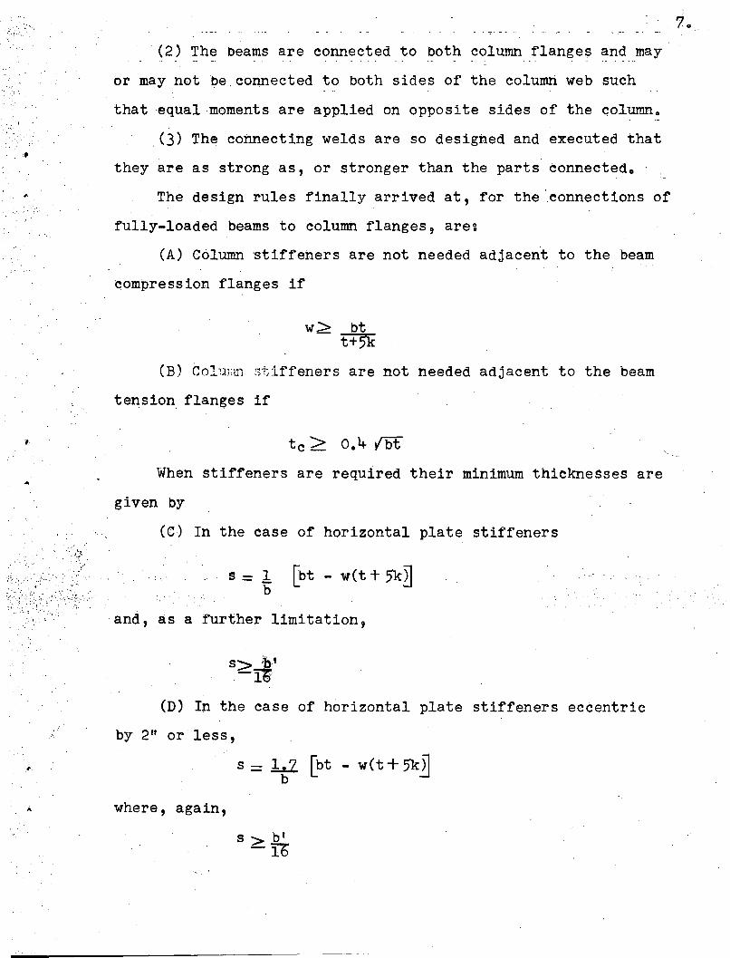
(2) The beams are connected to both column flanges and may
or may not be, connected to both sides of the column web such
that equal moments are applied on opposite sides of the column.
(3) The connecting welds are so designed and executed that
they are as strong as, or stronger than the parts connected. ' ,
The design rules finally arrived at, for the 'connections of
fully-loaded beams to column flanges, are~
(A) Column 'stiffeners are not needed adjacent to the beam
compression flanges if
w> btt+5k
(B) Colunffi stiffeners are not needed adjacent to the beam
tension, flanges if
When stiffeners are required their minimum thicknesses are
given by
~c (C) In the case of horizontal plate stiffeners
s = 1 [bt - wet + 5'k~b
;",
and, as a further limitation,
7.
(D) In the case of horizontal plate stiffeners eccentric
;' by 2" or less,
where, again,
s> b l
-Ib
Page 9
,
...
(E) In the case of vertical plate stiffeners,
S = bt -' wt+5'k
and"as a further limitation,
The limitations of this investigation, the analysis leading
to the above formulas and design examples are given in Part Co
8.
Page 10
,
•
OUTLINE OF INVESTIGATION
In this investigation st.udies are made of two-way and f.our- "',
way interior beam-to-column connections. Attempts are first made
to copy the most severe conditions found in practice, while in
later tests those items having a negligible effect on the connection
performance are eliminated. Beam and column sizes used are typical
of those in a building frame.
The primary purpose is the study of the connection under the'
following items:
(a) Stiffening requirements. What are the factors involved
in the behavior of the connection With and without stiffeners?
These assume significance in the application of "plastic',
analysis" to the design of tier buildings. To assure the format~
ion'of plastic hinges in the beams, the connection and the column
should be capaole of' sustaining a plastic moment in excess of,
or at least equal to, the plastic moment value of the oeams.
(b) Rotation capacity. This is another important feature
in the "plastic" analysis of structures since it expresses the
ability of the connection to sustain a full pla'stic moment
through the required hinge angle.
The beams were welded directly to the columns for t~ree
reasons:
1. The direct=welded connection has certain. advantages and
. may eventually be much used. in practice.
2. The emphasis in this illvestigatic.>I} be~ng upoIl the stUdy
of the stresses and strains in the column at the intersection, the.i: .. , . v" "..-'
Page 11
t
elimination of top plates and seat angles removed a few un-
necessary ~ariableso
3. The direct-welded connection, without seat angles, re-- - . - .,~, i ..
presents the severest loading on the column at the connection.
10 0
Page 12
II.
PART A
TEST PROGRAM
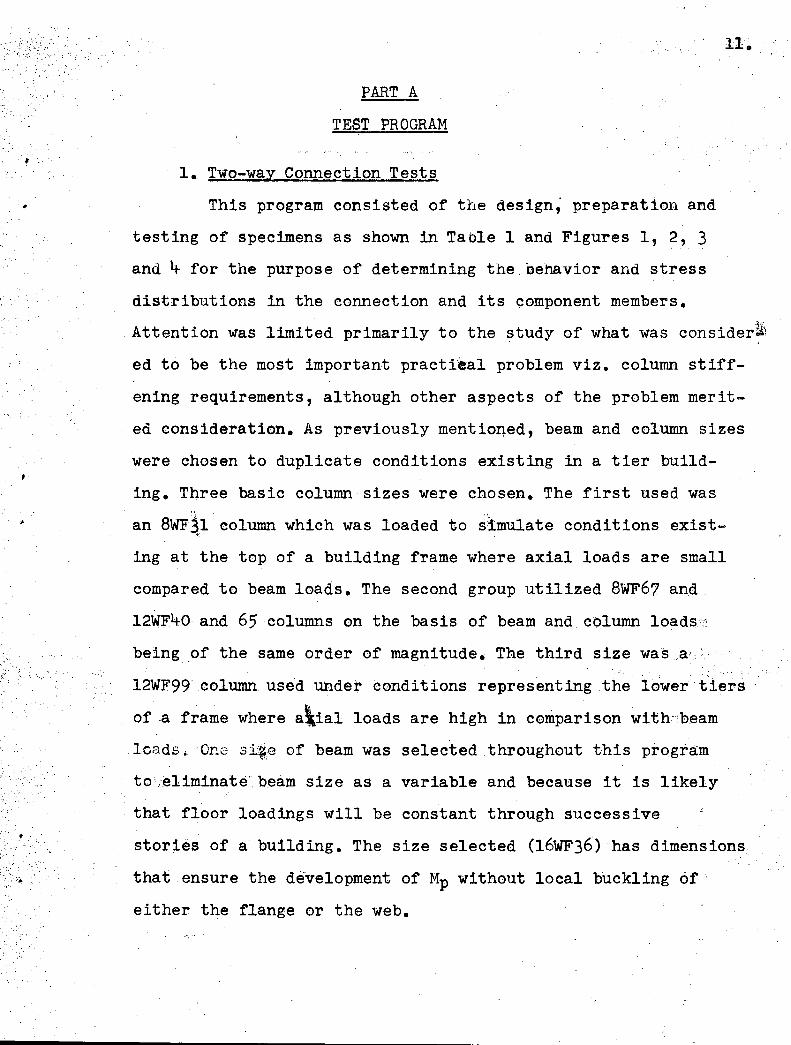
I., Two-way Connection Tests
This program consisted of the design; preparation and
testing of specimens as shown in Table 1 and Figures 1, 2, 3
and 4 for the purpose of determining the behavior and stress
distributions in the connection and its component members.\',.
Attention was limited primarily to the study of what was consider~~
ed to be the most important practi~a1 problem viz. column stiff
ening requirements, although other aspects of the problem merit
ed consideration. As previously mentioned, beam and column sizes
were chosen to duplicate conditions existing in a tier build-
ing. Three basic column sizes were chosen. The first used was
an 8WFl.l column which was loaded to ~~1mulate conditlons exist
ing at the top of a bUilding frame where axial loads are small
compared to beam loads. The second group utilized 8WF67 and.
12WF40 and 65 columns em the basis of beam and column loads.'.:
being of the same order of magnitude. The third size was ,a.,
12WF99 column used under conditions representing the lower tIers
of ,a frame where a\ial loads are high in comparison with':beam
loads. One sl~e of beam was selected throughout this program
tOi,eliminate', beam size as a variable and because it is likely
that floor loadings will be constant through successive
stories of a building. The size selected (16WF36) has dimensions
that ensure the development of Mp without local buckling of"
either the flange or the web.
Page 13
TABLE 1,
PROGRAM OF TWO-WAY DIRECT-WELDED BEAM-COLUMN TESTS
12.
.....• ..._.~-
Test Column Beam StiffenerNo. Shape Web* Flange* Shape Web* Flange* St~ffening Dimension
A-I 8WF31 0.288 0.433 16WF36 0 0 299 0.428 'None None
~\-2 8WF67 0.575 0.933 n 11 It II rr
A-4 12WF65 0.390 0.606 It " " " "A-5 12WF99 0.580 0.921 It " n It "
B-6 8WF31 0.288 0.433 It rr " Horiz. 3.9"x7/16n
plate stiffB-8 12WF40 0.294 0.516 It " " -eners, at 13•9"xl/4"
level oftension andcompress-ionflanges
C-9 8WF31 0.288 0 0 433 " n " Vertical 5/16":x::22"plate stiff
C-ll 12WF40 0.294 0.516 It " " -eners at 5/16"x22 t1
edges ofcol.flanges
D-12 12WFl.J,0 0.294 0.516 " " " Split tee ST6WF32.5stiffener 22 t1 ,long
. ,
H-I 8WF31 0.,288 0.433 " " " Doubler 5/16"X20n
i .. plate
* Indicates A.I.S.C. Handbook Value
The test program was divided into five groups of tests
depending upon the type of stiffening employed •. (See Figures
3 and 4). The specimens consisted of two l6WF36 beam stubs,
4'_6" long, welded directly to the flanges of the WF ~olumn
Page 14
':'.;.
r
130
sections as shown in Figures 1 and 2 .. The point of load appli
catioh on the beams was at a distance of 4'=0" from the face
of the column flange. Axial load was applied to the specimen- -- ---.
by an 800 kip Riehle screw type universal testing machine .. The
specimen was inverted in the machine to permit the beam loads
to be applied by mechanical compression jacks which were mounted
on dynamometers. The dynamometers, in turn, were set on bearing1
blocks seated on the table of the machine (See Figures 1 and 2)0
During fabrication much care was taken with the welding.
All welding was done by qualified welders using 3/l6 tt diameter
E6020 electrodes except that an E60l2 electrode was used for
the first ~/.1:.1d sSG There was much instrumentation on the
.,
:."'./:":
specimens, measurements being taken during the test of strain
distribution, deflections, rotations and tendencies towards
both local and lateral buckling of the beam. Figure 5 shows the
instrumentation in Series B, there being few differences in the
other series.
Before proceeding with a test, the column was checked for
axial alignment by observing the strains in four electrical
strain gages located at the same level in the column and mourited
at the outer edges of each column flange. The maximum variation
permitted in the gage reading was about 10% at full column
working load.
The sequence of loading in the tests was arranged in five
stages as follows:
(1) The column load was increased in five equal increments
to working load, Pw, with no load on the beams. (This axial load
was the same for the full height of the column).
Page 15
,
•
(2) The beam load was increased in four equal increments
to vlorking load, VW9 while maintaining working load, Pw,__ at
all times in the portion of the column "below"* the beams .. At
the conclusion of this stage the "upper tl portion of the column
sustained a load equal to Pw = 2Vw where
Pw= the column working load (refer to ~ection 2 .. 2 of
Appendix) and
Vw= the applied beam working load ..
(3) With t~is working load 9 VW9 maintained on the beams,
the column was then sUbjected to a first overload which in
creased the load in the "lower" portion to 1 .. 65 times the work
ing loac1a.nd~·;hjch increased the load in the "upper" portion
correspondingly .. This was done in three equal increments .. The
column load was subsequently reduced to working load in the
"lower" portion .. This left the specimen under the same loading
that existed at the end of stage 2 ..
(4) With working load 9Pw9 maintained in the "lower" sect
ion of the column the beams were loaded in increments until
failure occur~i~.
(5) As a last step in the testing with the connections
damaged, and with the last beam load still in the jacks 9 the
column was sUbjected to a second overload equal to twice the
working axial load ..
The test program was divided into five groups of tests
(namely A,B,C,n and H) depending upon the type of stiffening
*·"Below" or "lower" and "upperU refer to the portions of a
column below and above the beam as used in actual construction 9
not as in the laboratory ..
Page 16
Of
O'
employed (See Figures 3 and 4). Specimen dimensions are given
in Table 1,
Series A
In this group no stiffening was provided and the tests
ranged from the very light thin web 8WF3l column to the heavier
l2WF99. Connection A~l with the 8WF31 column failed by column
web buckling (See Figure 7) at a load slightly above the beam
working load~ namely 1.12Vw• Connection A-4~ with a thicker
web showed much straining, both tension and compression, in the
column webs opposite the beam flanges and failure occured by
column web buckling at a beam load of 44 kips, which is 1.82Vw•
In both cases the decrease in moment carrying capacity was quite
rapid but no local buckling of the beam flanges was experienced.
The column flanges in Test A-4 deformed considerably on the
second column overload.
Specimens A-2 and A-5 behaved extremely well without stiff
ening. Local buckling of the beam flanges occured at 2.08Vw and
2.26Vw respectively. The loss of beam strength was quite gradual
and the specimens sustained large rotations before the tests
were concluded. Upon application of the second column overload
additional deformation of the column flanges was noted, but no
other effect on the column was observed that would indicate that
column failure was imminent.
Series B
Horizontal stiffeners were placed across the column
flanges at the level of the beam flanges in this series as
shown in Figure 3. These stiffeners were welded to both column
Page 17
flanges and to the column web o In test B=6 the stiffeners were
of a tilickness equal to the beam flanges but in B=8 the stiff=
eners were thinner o This is a very strong type of connectien as
borne out by. the test results 9 as both exhibited excellent load
and rotation capacities o Both specimens suffered local buckling
of the beam compression flanges at the onset of the strain hard=
ening range and the increase in beam load above this level was
slight o The decline of strength from the maximum value was grad
ual as jacking continued and no harmful effects were observed
in the column stiffeners beyond the presence of a few strain
ljnes~ The principal deformations occurred in the beams o
Series C .
The stiffening provided in this series of tests con
sisted of plates positioned vertically near the edges of the
column flange as shown in Figure 30 The stiffeners were arbit
rarily made the same thickness as the column web o Both con
nections C=9 and C=ll carried the required loadso In both tests
there was evidence of some slight local buckling on the beam
compression flanges at loads of approximately 2 ol7Vwo In both
tests, the column web between the beam compression flanges
buckl.ed .. 1'01' specimen C-ll the critical load at which this
effect was first noticed was lo97Vwo In C=ll weld failure
occurred just after this in the tension flange butt welds o The
tear occurred at one end of the tension flange butt weld owing
either to failure of the welder to weld out completely onto the
run=out pad 9 to stress concentrations caused by the stiffener,
or to a lateral moment o In test C=9 the connection continued to
carry load until .at approximately 2 ol6Vw the south stiffener
Page 18
17.
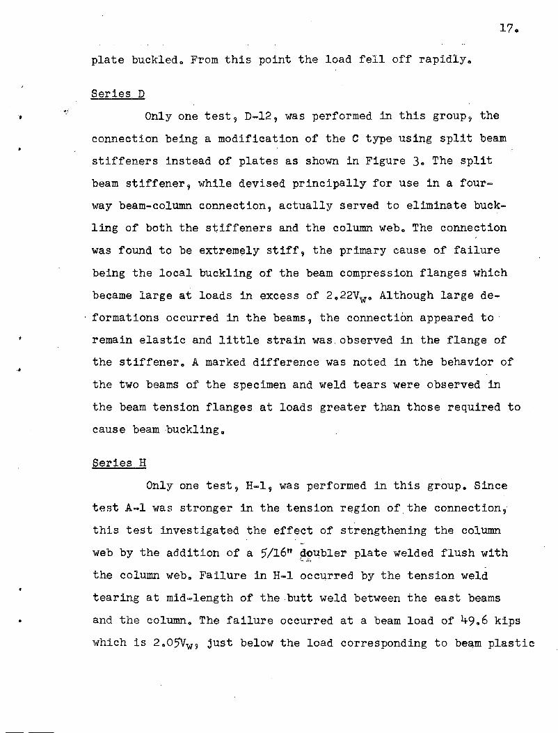
plate buckled o From this point the load fell off rapidly.
Series D
Only one test 9 D-12, was performed in this grouP9 the
connection being a modification of the C type using split beam
stiffeners instead of plates as shown in Figure 3. The split
beam stiffener 9 while devised principally for use in a four-
way beam-column connection 9 actually served to eliminate buck
ling of both the stiffeners and the column web. The connection
was found to be extremely stiff, the primary cause of fai~ure
being the local buckling of the beam compression flanges which
became large at loads in excess of 2.22Vwo Although large de
formations occurred in the beams, the connection appeared to .
remain elastic and little strain was observed in the flange of
the stiffener. A marked difference was noted in the behavior of
the two beams of the specimen and weld tears were observed in
the beam tension flanges at loads greater than those required to
cause beam buckling.
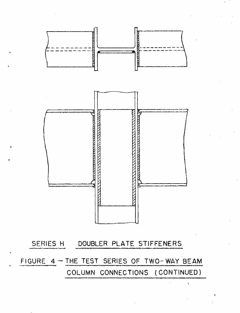
Series H
Only one test 9 H-l, was performed in this group. Since
test A-I was stronger in the tension region of the connection,
this test investigated the effect of strengthening the column
web by the addition of a 5/16" ~~~bler plate welded flush with
the column web. Failure in H-l occurred by the tension weld
tearing at mid~length of the butt weld between the east beams
and the column. The failure occurred at a beam load of 49.6 kips
which is 2.05Vw9 just below the load corresponding to beam plastic
Page 19
•
18.
moment. The rotation was adequate but the load fell off rapidly
after the tearing of the weld o
The A-series of tests showed high stress concentrations
at the center of the beam tension flanges 9 a condition which
becomes more aggravated at values above working load. The stress
distribution on the compression flanges in the B series was
uniform on the whole while in the tension areas the stresses
were somewhat higher in the center. For the C series the distrib
ution of stress was uniform in both flanges at Vw while at 1.5Vw
high tensile stresses occurred at mid flange. Specimen D=12 also
showed a generally uniform distribution throughout. Both C-ll
and D-12 however appeared to suffer from eccentric effects as
indicated by the higher stresses on one side of the flange and
this probably caused the weld tearing. Specimen H-l showed a
stress concentration tn~"the center of the beam tension flange 9
the concentration being very pronour.ced at 1.5Vw•
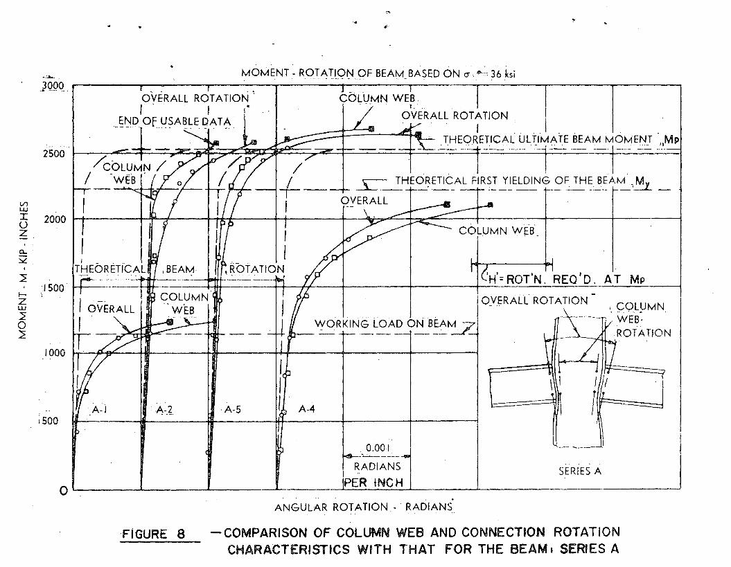
The results in Figures 6, 8 and 10 show that the column~
of the A and the H series, with no column flange stiffening,
are not as stiff against rotation as are the l6WF36 beams which
framed to the columns. In the B tests (See Figure 9) the stiff-
eners provide the equivalent of beam flanges to the columns,
and the columns become as stiff against rotation as are the
framing-in beams. The same applies to the C tests as shown in
Figure 9. From an inspection of the strain readings taken on
the C specimens it is noted that the column web carried a
major part of the applied load, approximately 2t to 3 times as
much as the plate stiffeners at beam working load.
Page 20
19.
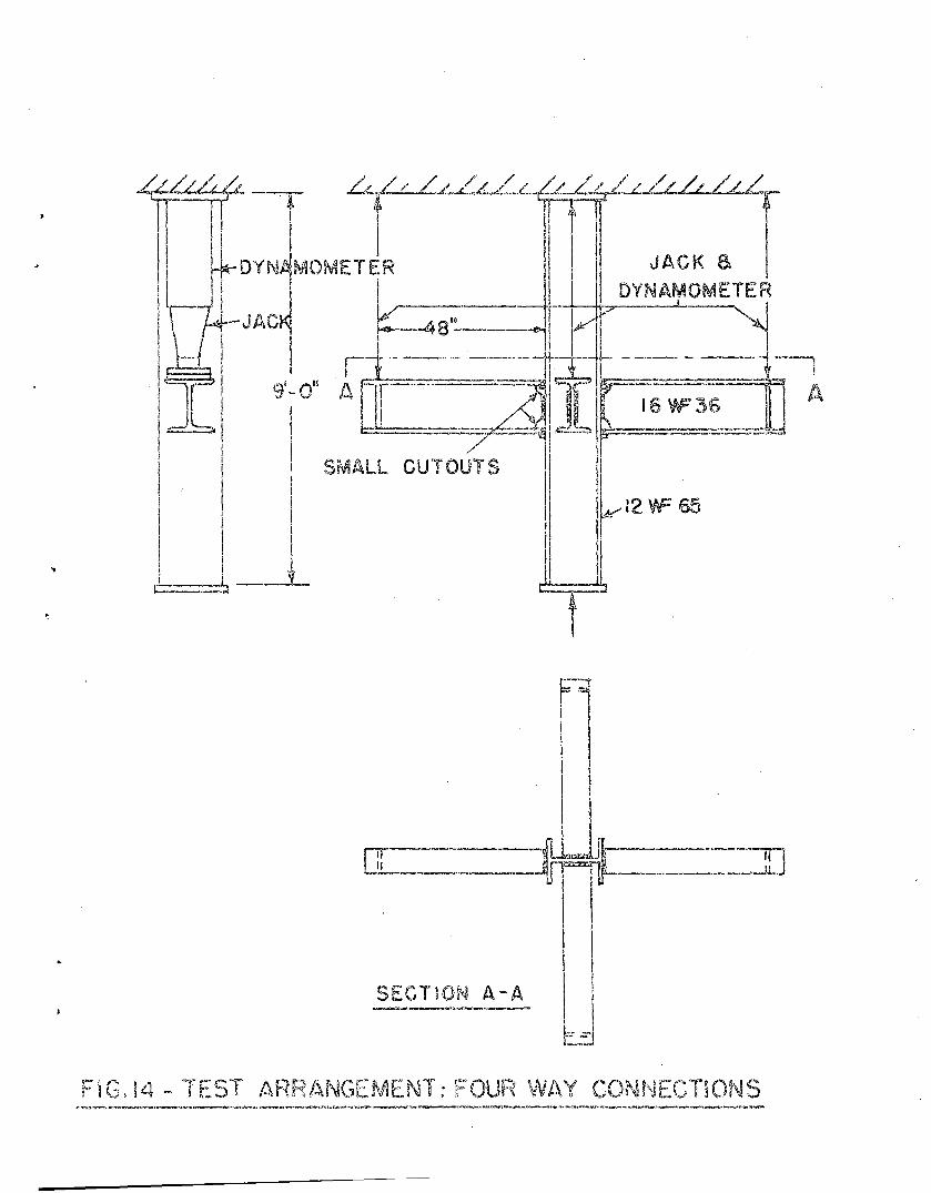
2. Four-way Connection Tests.
This program consisted of three specimens with details
as shown in Table 2 and Figures 14 and 15. Test AA is similar,..:'
to Test A...4 of the "Two-way" series except for two additional
16WF36 be,ams framing into the column web and directly welded
thereto. In the same manner Test DD is similar to Test D-12 of
the Two-way series. Test BB was exploratory in nature and does
not have its two-way counterpart. The beams framing to the
column flanges were l6wF36 as before and were direct-welded,
but the other pair of beams were 12WF27 t the tension flanges
of which were welded to horizontally Flace~ column plate
stiffeners, the compression flanges resting on a tee-type seat
which also acted as a column stiffener (but 4" away from its
ideal location as a stiffener).
Page 21
•
. .'
•
20,.
TABLE 2
PROGRAM OF FOUR-WAY CONNECTION TESTSJ ...
Test Column . Beam StiffenerI
Size Web,w Flange,tc Size yteb,t ' Flange,t Type Size
AA 12WF65 0.39 0.606 16WF36 0,.299 0.428 None None
BB.
12WF40 0.294 0.516 l6WF36' 0.299 0.428 Horiz. t"thickl2WF27 0~240 0.400 plates
thatservedas topplateand as
I seat(plate)
l6WF36I .
0.428 ST6WF32.5DD l2WF40 0.294 0.5'16 0.299 Splittee 22" . long
-, stiff-ener
Thespecimen~ were fabricated of the WF sections indicated in
Table 2, the beams being each 4'-3" long and the columns 9'-0"
·long.
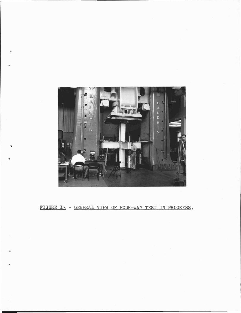
The testing was done in the five million pound Baldwin Hamilton
machine which provided ample' space for placing these specimens and
for the later~l supports, Figure '13 showing a test in progress.
The test arrangement was similar to that for the Two-way tests,
Figure 14 showing the test arrangement oriented to show the
positioning of loads as found in a typical building connection.
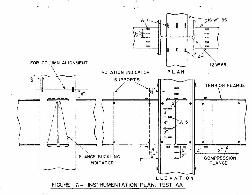
The measurements taken were much the same as in the two-way tests,
Figure 16 showing the instrumentation plan in Test AA •
Page 22
21.
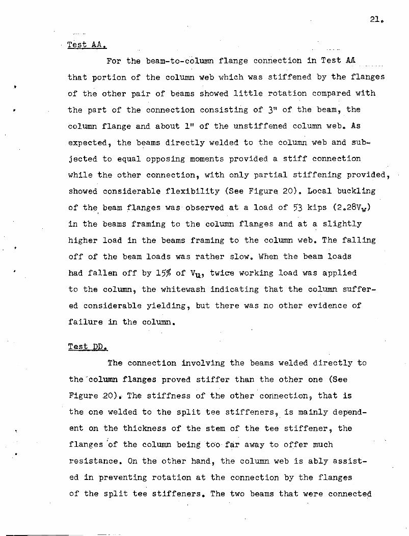
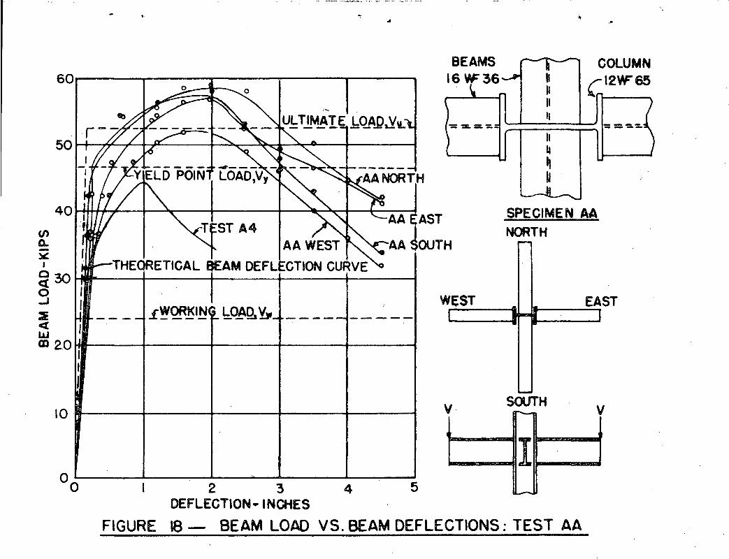
Test AA.
For the beam-to-column flange connection in Test AA
that portion of the column web which was stiffened by the flanges
of the other pair of beams showed little rotation compared with
the part of the connection consisting of 3" of the beam, the
column flange and about I" of the unstiffened column web. As
expected, the b~ams directly welded to the column web and sub
jected to equal opposing moments provided a stiff connection
while the other connection, with only partial stiffening provided,
showed considerable flexibility (See Figure 20). Local buckling
of the beam flanges was observed at a load of 53 kips (2.28Vw)I
in the beams framing to the column flanges and at a slightly
higher load in the beams framing to the column web. The falling
off of the beam loads was rather slow. When the beam loads
had fallen off by 15% of V~, twic-e working load was applied
to the column, the whitewash indicating that the column suffer
ed considerable yielding, but there was no other evidence of
failure in the column.
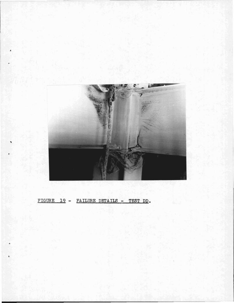
Test DD e
The connection involving the beams welded directly to
the .- column flanges proved stiffer than the other one (See
Figure 20). The stiffness of the other connection, that is
the one welded to the split tee stiffeners'} is mainly depend
ent on the thickness of the stem of the tee stiffener, the
flanges 'of the column being too far away to offer much
resistance. On the other hand, the column web is ably assist
ed in preventing rotation at the connection by the flanges
of the split tee stiffeners. The two beams that were connected
Page 23
;
to the stiffeners had very good load and rotation capacities~
but the eas'c and west beams that were connected to the column
flanges just reached the required ultimate load and showed a
lesser rotation capacity caused by a butt weld failure start
ing at a load of 4-9 kips (2.l8Vw). The first crack occurred
in the west beam at the interface between the column flanges
and the end of the butt weld to the beam tension flange and
increased until weld failure penet:rated to the fillet welds
connecting the beam web to the column flange. The tension
flange butt welds of the north and south beams 9 connected to
the stiffeners, had v~ry sma~l cracks starting at a load of
55 kips, but the,~ did not progress any further since 9 at this
load, the beam compression flanges buckled.
Test BB g
The connection involving the l6wF36 beams 9 welded
directly to the column flanges, proved to be relatively stiff.
The connection involving the l2WF27 beafusframing:pgth~ seats
and top plates was considerably more flexible than an\
equivalent l2WF27; nowev:e.rthJs :flexibi:;L:tt;y did not pr,event
the cO.nI}~9tion from fUllym'~'etingthe established criteria
for as;;:, tisi'actol'Y connection.
Page 24
t'
, .
: '" :
3o SirnulatedConnection Test's,
After examirl1ng' the results of the 'cwo=way tests it was
realiZ~d t,hat practically the same st~ess and strain state in
" a connection could be produced'byfar simpler and ,quicker. , . '.. . . '.
tests 0 TheSe t~sts were o'fthree, types' descri,bed as follow~g, ,. . "
. . " '. . .
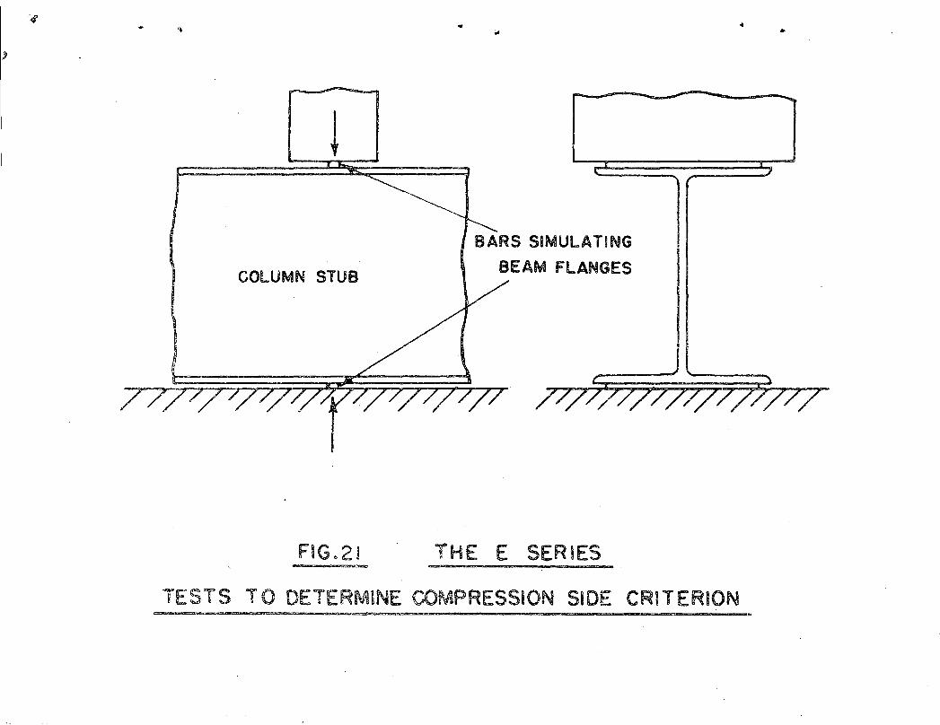
, '3 .. 1 Tests To Determine Column Web Buckling Criterion,
These tests s'imulated the lower' part' of the connection
in which the'beam was in compression against the column and, , ,
consisted of a stub column compresse<i at the flanges between..
two bars 9 the size of the 'bars being· made the same as the,sect=
ion of the flange of the simulated bea'm o '
The size Qf the,ba.rs was kept constant at 7"'x 7/16"9
,simulating the flange ,of the 16WF36 be,am used in all the' two~
'waytests o The bars were , tack, welded 'to the flanges at, the mid';' ". . . .' .' . . .
len'gth'.of the stub c.olUll1IlsCjwhich were approximately 3u=0", '. '. . .
'long o ,The specime!lw~s then te,sted inthe 300 kip Baldwin test=
ing machine,withthesimtilated column'in a horizontal position
(See Figure 21). '
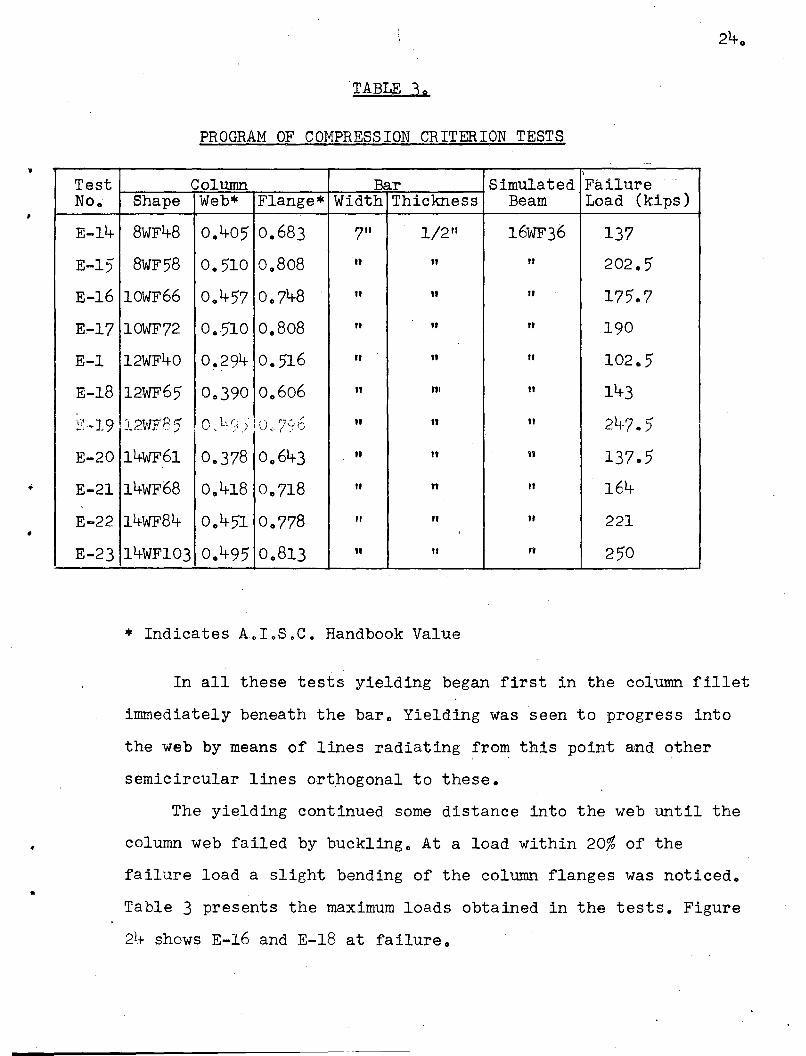
Eleven t~sts were carried'out 9 the details of which are
given in,TabIeJ • ', .
Page 25
,
..
TABLE 30
PROGRAM OF COMPRESSION CRITERION TESTS._-
\
Test Column Bar Simulated FailureNo. Shape Web* Flange* Width Thickness Beam Load (kips)
E-14 8WF4-8 0.405 0.683 7" 1/2" 16WF36 137
E-15 8WF58 0.510 0 0 808 n It " 202.5
E-16 10WF66 0 0 457 0 .. 748 It n " 175.7
E~17 10WF72 0.510 0.808 " It " 190
E-l 12WF40 0.294 0.516 It n " 102.5. ,
E-18 12WF65 0 0 390 0 .. 606 n "' n 143
,7' ,~] 9 " 2~rPr:: 0,. LL 1))' () ,U ~iS'{5 It n It 21,-7 .. 5...... . ' -'- .. ~ J'! '.- .J
E-20 14WF61 0 .. 378 0 0 64-3 It It u 137.5
E-21 14WF68 0 0 4-18 0.718 " " " 164
E-22 14WF84 0 0 451 0 0 778 " " It 221
E-23 14WFI03 0.495 0 .. 813 II " n 250
* Indicates AoIoSoC o Handbook Value
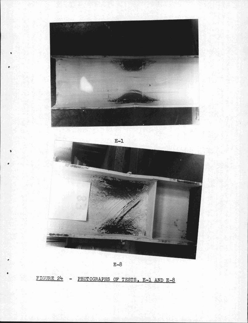
In all these tests yielding began first in the column fillet
immediately beneath the bar .. Yielding was seen to progress into
the web by means of lines radiating from this point and other
semicircular lines ortpogonal to these.
The yielding continued some distance into the web until the
column web failed by buckling .. At a load within 20% of the
failure load a slight bending of the column flanges was noticed o
Table 3 presents the maximum loads obtained in the tests. Figure
21+ shows E-16 and E-18 at failure.
Page 26
3 0 2 Tests to Determine Connection Tension Criterion
These tests simulated the upper part of the connection
in which the beam flange is in tension 9 and consisted of two
equal plates welded to the flanges of the column 9 ,the size
of the plates being made the same as the section of the flange
of the simulated beam o Tension was applied to these plates by
means of the BOOk Riehle testing machine o The dimensions of
both the plate and the column flange were varied to study
their respective influences o The effect of changing the column
flange thickness was further studied by repeating certain of
the tests with the column flanges machined to about half the
original thickness 0 The plates simulating the beam flanges
were also changed in size 9 keeping the column section constant~
Table 4 summarizes these tests o The plates were butt welded to
the centers of a stub column of length about 3u=0" as shown
in Figure 22 and the specimen then lined up in the testing
machine with the stub column horizontal.
The first yield lines were noted in the column fillet
immediately beneath the plate at a load of about 40% of the
ultimate load o The yielding proceeded
(a) into the column web
(b) underneath the column flange parallel to the plate
and
(c) on the column flange starting from the center of the'
weld in lines parallel to the column web o
"
By the time failure occurred 9 yielding had progressed 2"
into the web in tests F=19 F=2 9 F=3 9 F=4 9 F::.5 9 F-9 and F=lO
and had progressed across the web in tests F=12 9 F=13 9F-14
Page 27
, #
•
•
26.
and F-15. All specimens except F=19 F=9~ F-14 and F~15 failed
by the occurrence of a crack in the center of the butt w~ld~
the fracture taking place after noticeable flange bending. F=l
and F-9 cracked in the column fillet while F-14 and F-15 suffer"-
ed a tearing out which started from the outside of the column
flange and proceeded to its center. The tear pulled out part
of the column flange material. Table 4 presents the maximum
. loads obtained in the tests. Figure 24 shows F-4 and F=15 at
failure.
TABLE 4"
PROGRAM OF TENSION CRITERION TESTS
Test Column Plate Failure Method ofNo. Shape Web* Flange Width Thick (load) Failure
* ~ness kinsF-l eWF3l' Oo28e 0.433 7" 3/4" 100 Crack in column fillet
F-2 8WF3l 0.288 0.433 7" 7/16" 95 Crack in center ofweld"
F-3 l2WF65 0.390 0.,606 8t" 5/8n 149 "F-4 l4wF68 0.418 0.718 8tn 5/8n 167 n
F-5 l4WF84 0.451 0.778 lIt" 7/8" 212 n
F-9 l2WF65+ 0.390 0 0 606 8tn 5/8" 82 Crack in column fillet
F-IO l4WF8lt+ 0,,451 0 0 778 lIt" 7/8n 125 CraC,k in center of'. weld.
F-12 12WF65 0.390 0~606' 8t" It" 189 yt
14wF68 0.418 0.718 8tn It"c
F-13 199 tI
F-14 8WF67 0.575 0.933 7" 3/4" 256 Crack at outside of--- weld ..
F-15 14WF176 0 0"820 1~313 lIt" 7/8" , 4~4 nI
* Indicates A~IoSoCo Handbook Value
+ Column Flange Machined to 5/16"
++ Column Flange Machined to 3/8"
Page 28
•
"
27.
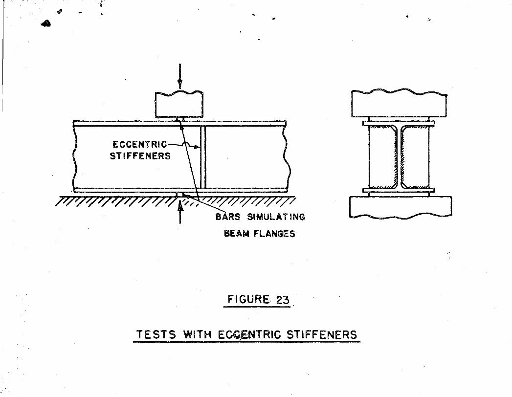
3.3 Eccentri'c' Stiffener Tests,
In four~way connections the columns may be stiffen
ed 9 opposite the compression flanges of the flange-connected
beams 9 by the support provided by the compression flanges or
the seating plates of the beams which frame into the column
web. In a connection such as specimen BB (Figure 15)9 where
the flange=connected and web-connected beams, are of different
depths 9 their compression flanges are not opposite 9 and the
degree of such stiffening is questionable. To determine the
degree of such stiffening a series of tests were carried out
on l2WF40 and l4WF6l column stubs approximately 4°-0" long.
The columns were compressed between bars for cases of 0 9 2",
4" and 6n eccentricity as shown in Figure 23 by means of the
300k Baldwin machine 9 the tests being similar to the compress=
ion criterion tests in Part 3.1. Included in the tests on the
l2WF40 was one (E-3a) in which the compression region of test
BB was simulated = that 1s 9 a Tee seat was added to a stiffener
of 4" eccentricity,
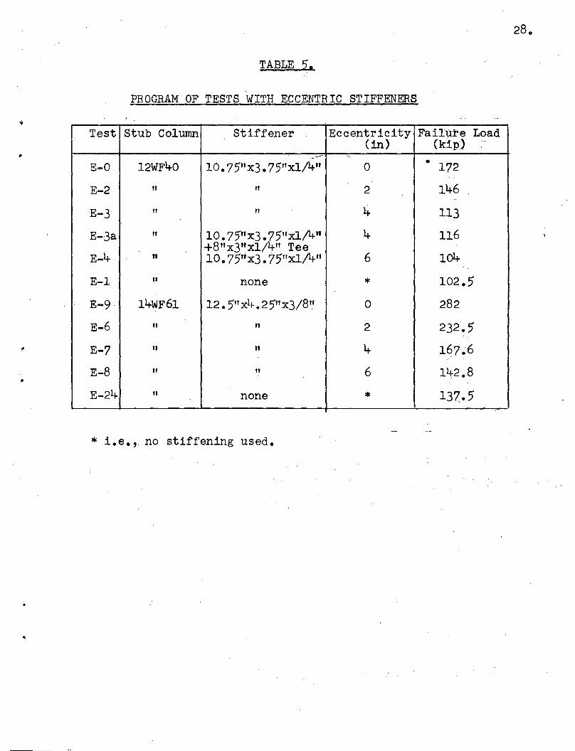
The results of the eccentric stiffener tests are given
in Table 5. As can be seen from both series the stiffeners of
eccentric:i.ty 2" provided about 65% of the stiffening action
of the conceritric stiffener whereas the stiffeners of
eccentricity 4" and greater provided less than 20% of the con
centric stiffening action.
Page 29
•
TABLE 5.
PROGRAM OF TESTS WITH ECCENTRIC STIFFENERS
Test Stub Column Stiffener Eccentricity Failure Load(in) (kip)
..---- "
E-O 12WF40 10. 75tt x3. 75"xl/4n 0 • 172
E-2 " " 2 146
'E-3 " " 4 113
E-3a " 10.75"x3. 75"xl!4n 4 116+8"x3u xl/4" Tee
6 104E-4 tt 10. 75"x3.75"xl!4"
E-l " none * 102.5
E-9 14wF61 12. 5"x4. 25"x3/8" 0 282
E-6 " " 2 232.5
E-7 " " 4 167.6
E-8 " " 6 142.8
E-24 " none * 137.5
* i.e., no stiffening used •
28.
Page 30
•
290
PART B
DISCUSSION OF TEST RESULTS
1. Connection Requirements
In a beam column welded connection there are several
regions which are subject to local overstress and therefore
it appears pertinemt, before discussing the behavior of the
tested connections, to define a satisfactory connection. It
is defined as one which is capable of developing the theoretical
maximum moment of resistance of the beams (the "plastic moment")
when ',",or}:ing axial load is on the column. A desirable additional
quality Of a satisfactory conne9tion is, that it maintain its
moment capacity for a considerable rotation at the ultimate
load. The rotations required at plastic hinges (namely, the
"hinge angle") for a variety of practical structures have been
dete:r;mined in Reference 4- and its particular applica~ion to
this investigation is treated in Section ~.2 of the Appendix.
2. Two-way Connection Tests
A significan.t feature of these tests was the ability
of the connections to develop the strength of the beams. In
all cases except two (A-l and A-4-) where column web crippling
was responsible for failure - the beams were not only able
to reach .their predicted ultimate load, but were able to sus
tain this load over considerable rotation.
Local buckling is a factor which might influence the value
of the plastic moment of a beam section and of its rotation
capacity. Haaijer (6) has determined the properties of sections
that will buckle just at the onset of strain hardening. The
Page 31
,
..
width to thickness ratiq of the beam flange ~l bit, must not
exceed 17, and the ratio, d/t', (beam depth to web thickn(3ss). - ,.. .
must not exceed 55. The beam section chosen (16WF36) was just
within these values in both these respects, with the result
that local buckling, as predicted by Haaijer, coincided with
the beginning of strain hardening and was not detrimental to
the strength of the connection.
In comparing the theoretical and experimental moment~
rotation curves (Figures 8, 9, and 10) in the elastic range,
the connections are not as stiff as the 16WF36 beams. This
flexibility j.s of course due to strains in the column. These
were greatest in Specimen A-I, with A~4, B-6, B-8, C-9 and
C-II also showing noticeable deviation from the theoretical
curve.
The structural adequacy of a particular type of welded
connection can be ascertained in part by comparing the moment
and rotation capacity of the beams with that for the column
with the consideration that the column must have equal or
greater moment capacity than.the beam but it need not
necessarily be as stiff. When the "column has the requisite
strength the desired rotation capacity is supplied jointly by
the column and the end portions of the beams. Specimen A-I with
its unstiffened, thin-web column section is a notable example
where column web buckling was the principal cause for the high
rotations at low moments. In border line cases, as for example
A~49 the buckling of the column web did not become excessive
and the deformations are due to a combination of high inelastic
strains in the column web in areas of both tension and compress-
Page 32
•
31.
ion and to some web buckling. Thus this investigation clear~
ly demonstrates the importance of the column web opposite the
compression flanges of the beams.
From observation of strain gage readings it can be cal-
culated that the vertical plate stiffeners of Series C in the
elastic range, each transmitted only about 3/16ths of the
forces coming from the beam flanges and the web transmitted
5/8ths. However, since the prime purpose of this type of
connection is to afford a convenient four-way connection, the
plate needs to be positioned flush with the edge of the column
flange.
J\,lthough there were high stress concentrations, at the
centers of the butt welds in the Series A and H tests, it was
noted that no weld failures occurred until after excessive
rotation had taken place.
3. Four-way Connection Tests.
All thre~ specimens passe.d the criteria by both
possessing the strength to develop the theoretical beam
plastic moment and qy sh()wing sufficient rotation c~pac1ty
at peak loads.
Test.AA, as shown. in Figure 18, was stronger than its
two-way counterpart, T~st A-4. This evidently shows that the
~tiffening action provided by the two beams framing mito the
column web strengthens tpe connection more than it is weaken
ed by consequences of the triaxial stresses. In both tests DD
and D-12 the split beam stiffeners effectively prevented any
buckling of the connection. Test BB cannot be com}!)ared with a./
Page 33
..
,.
•
..
two-way test since it had no two-way counterpart.
4. Effect of Axial Load,
In both the two and the four-way tests the column
axial load had little effect on the strength and rotation
capacity of the connection. The columns showed no particular
signs of distress when subjected to an axial load o~ 1.65 x
*working load except that specimen BB showed straining in the
web of the l2WF40 column. Since the strain lines were not
found throughout the cross-section it may be presumed that
residual stresses may have been at least partly responsible
for the appearance of these strain lines. Further, at the end
of each test, with the final beam loads still applied, twice
column working load was applied with no evidence of marked
distress in the column.
5. Correlation of Tests,
5.1 Tests to Determine Compression Criterion
These Series E tests give much information about the
actual resistance of the web of a column to local forces applied
at the flanges and they are intended to simulate the compress-
ion region of a connection. However in so doing they neglect
1. the effect of the column axial load
2. the effect of the tension region of the connection on
the compression region
3. the effect of the compression from the beam web •
~---------------------~
* working load corresponds to ~n average axial stress of
14.5 k.s.i.
Page 34
•
,
The discussion in Section 4 indicates that column axial
load has neglig~ble effect whereas the stress concentrations
caused on the tension and compression region~ are so far apart
that any interaction would be small. If the tension region of
the connection does not fail then we can assume that its effect
on the compression region is negligible. The compression fro~
the beam web does have some effect and this probably caused
the differenc,e in results in the follOWing two sets of tests.:. ''', ".
Test E-18 on a l2WF65 stub column failed at a simulated beam
flange load of 143 kips, whereas test A-4 in which the l2WF65
section ':las used in an actual connection failed at a computed
load of 110 kips from the beam flange together with a computed
beam web load of 40 kips.
Test BB showed much straining in the web of the l2WF40
column at a beam flange load of 110 k whereas the simulated
test with no beam web force failed at a simulated beam flange
force of 116 k (See Test E-3a, Table 5).
5.2 Series F - Tests to Determine Tension Criterion
The ·.simulated tension side tests ignore
1. the effect of the column axial load
2. the effect of the compression region of the connection
on the tension region.
For similar reasons to those in Section 5.1 both of these
effects should be negligible. This is borne out by the results
of tests F-2 and H-l. Test H~l, in which an actual connection
was SUbject to axial load, suffered a weld failure at a beam
flange tension load of approximately 100 k while test F-2, a
simple tension test suffered the same failure at 95 k. All
Page 35
..
qf the tension failures occurred because of excessive strain
ing in a region close to the column fill~t and the center of
the weld, as a result of the outward yielding of the column
flanges. The shear stresses resulting from the narrowing of the
tension plates due to the Poisson effect may have influenced
the mode of failure in tests F-14 and F-15e These two specimens
were ~der much higher unit tension than the other F specimens.
5,.3 Eccentric Stiffener Tests o
Both series of tests showed a rapid decline in the
effectiveness of the stiffener for eccentricities greater than
111 thf.; tc ~:t s on both the 12WF40 and 111·WF61 column stubs
tpe stiffeners with 2"; eccentricity proved 65%: as effective
as the concentric stiffeners while those with 4n eccentricity
were qnly 20% as effec.tive as the concentric stiffeners. Stiff
aping with still greater eccentricity had virtually.no effect o
For design purposes it would probably be advisable to neglect
the resistance of stiffeners having eccentricities greater than
Page 36
•
"
PART C.
ANALYSIS AND DESIGN OF CONNECTIONS •
35.
Page 37
•
and also In the Appendix e Items (4) and (5) have been discussed
in Part B,their effects having been deduced from the observ~
ation of tests. It has been explained that the effects of column
axial load can be neglected and that the stiffening action
of the second pair of beams strengthens the connection more
than the triaxial stresses set up in the column web will weak~
en it. A conservative procedure would then be to analyze the
connection as if the second pair of beams were not present.
Item (6) has been investigated both analytically and experi
mentally. The rotation required of connections can be found
from Reference 4,. This of course varies with the beam load-
ing, size and span but in Section 1.2 of the Appendix there
is calculated a sample value of the required rotation which
will be greater than that required by most connections. For
purposes of comparison this value has been plotted on
Figures 8, 9, 10 and 20 which show moment rotation curves
of tested connections. Inspection does show that all tested
connections do have sufficient rotation capacity. Moreover
if the connection is made stronger so that it is much stiffer
than the beam at Mp then the necessary rotation will occur in
the end of,the beam o
1.1 Analysis of Compression Region of Connection
The critical item in this region in an unstiffened
connection is the buckling of the column web. From experi
mental evidence as discussed later (for illustration see
Figure 27) a conservative estimate of the strength of the
compression region of a connection could be obtained by
Page 38
J'
37.
ass~ing that the resistan~e supplied by the column web in .
resisting the beam flange force is' 6 y wet + 5k).
This implies '. that 9 as shown in Figure 25 9 there is a
distribution of stress on a 2.5:1 slope to the column nk-lirie"
so that the resistance of the column web is equivalent to a
uniform resistance supplied over the 1ength(t +5k). Hence,
for a connection with no stiffeners
Qc,='O"'y w (t+ 5k) (1)
Now the force supplied by the beam flange when the beam
is under, plastic moment is btoy so the minimum column web
thickness required is given by
bt(1'"'y = (Jy w (t + 5k) oe ~ •••••••••• (2)
or w = btt+5k
~ 0 .~ •• 0' 0 0 e e It 0 • It 0 0 e 0 0 • 0 •••• 0 •• ' (3)
In cases where w~ bt and stiffeners are requiredt+5'k
formula (2) 'is modified to include the resistance of these
. stiffeners.
btlJ"y = cr~w (t ~ 5k)-r o-y Ast (4)
In the case 'of horizontal plate stiffeners Ast may be. .:, :~~, . ", .' :'J. '.~. .~', ,,_ ..
appre>ximated
,Hence,
as
~-~--\Ast = . sb
\ ---
o • o' O' 0 0'. 0 ••••• ~' •••' '•• ,( 5)s = bt - w (t + 5k)b
. As a further :.limitatp.on (See Section 1.1 of the Appendix),
Page 39
s~ ••••• ~.·•.••••••••'•• ~.•,.•• ·.~ •••••• (6)
..
,
Tests C-9, C-ll and D-12 indicate that the vertical plate
stiff~pers carry about half'the stress that the column web
do'es. Making this assumption, formula (4) becomes in the case
of vertical plate stiffeners,
bt(fy = cr w (t + 5'k)+o- 2s (t t- 5'k),y +-
so that
S-- bt - w ' (7)• • • • • • e' • 0 • • • • • • • • • • • '. • • •
t + 5'kAs a further limitation (See Section 1.1 of the Appendix),
, •.•••••••••••••••• ~ .•..• _••••• ~(8)
, '.
In those cases ih which the beam flange width 1s mucb
less ~han the column flange width these C type stiffeners would
not be as effective as assumed and it would be inadvisable to(.- r
rely on their stiffening action when the column web is greatly, 1
qeficient according to formula (3)'~'.. '
Eccentric Stiffening
Since the testing done on eccentric stiffeners was very
limited, any results derived from this testing concerning their
action cannot be very conclusive; however, since very light
columns were used, then these results should if anything be
conservative.
Tests have indicated that horizontal plate stiffeners'
of eccentricities greater than 2" have very little stiffening
action.' A con'servative design procedure then would be to
Page 40
..
390 .
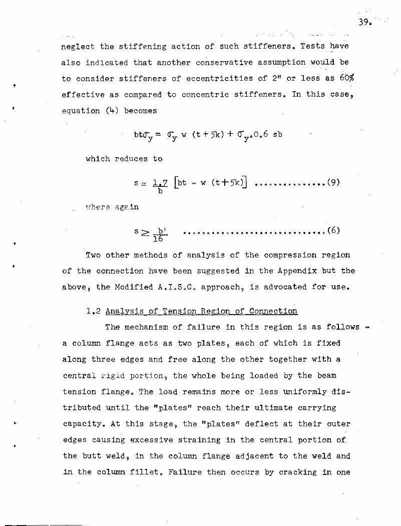
neglect the stiffening action of such stiffeners" Tests have
also indicated that another conservative assumption would be
to consider stiffeners of eccentricities of 2u or less as 6b%
effective as compared to concentric stiffeners" In this case,
equation (4) becomes
which reduces to
•s> b i
-Ib•• 0 coo 0 (l e GOO' eo l) 6 S" f) eO •• 0 t) G ••• e (6)
•Two other methods of analysis of the compression region
of the connection have been suggested in the Appendix but the
above, the Modified A.IoSoC o approach, is advocated for use.
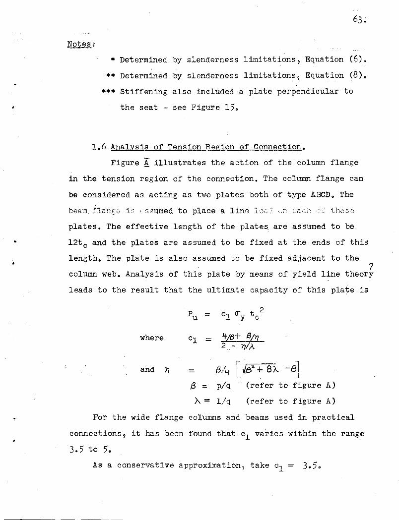
1,,2 Analysis of Tenslon Region of Connection
The mechanism of failure in this region is as follows
a column flange acts as two plates, each of which is fixed
along three edges and free along the other together with a
central rigid portion, the whole being loaded by the beam
tension flange" The load remains more or less uniformly dis
tributed until the "plates" reach their ultimate carrying
capacity. At this stage, the liplates" deflect at their outer
edges causing excessive straining in the central portion of
the butt weld, in the column flange adjacent to the weld and
in the column fillet. Failure then occurs by cracking in one
Page 41
..
•
of these reeions<) The "plates" are under bending action so their
ultimate capacity depends on the square of their thickness.
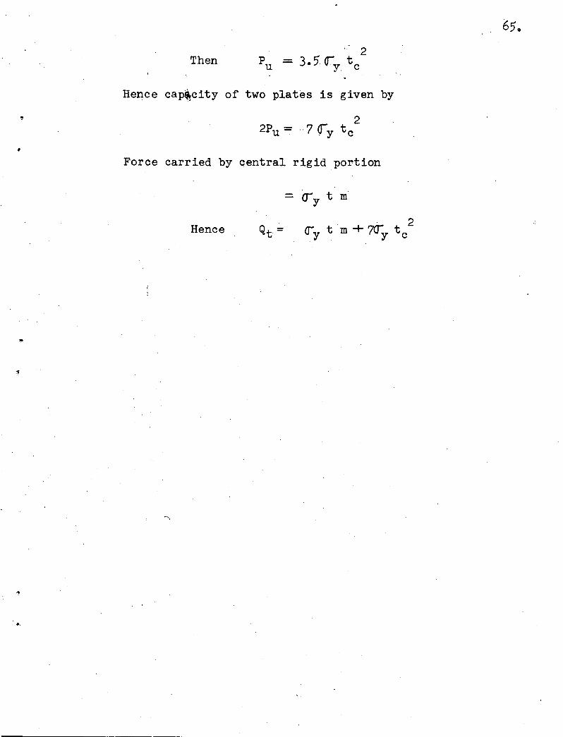
Analysis in the Appendix (Section 1 06) illustrates that a
conservative estimate of the capacity of this "plate" for2
wide flange columns is 3050y t c 0 The central rigid part of
length 'm' adjacent to the .column web will be highly strained
and hepce will carry a force corresponding to its area at
yield stress. Hence
2Qt = ery tm + 7<ry t coo 00 0000000 •••••••• (10)
The force in the beam tension flange when plastic moment
is on the beam is bt~yo To give 20% conservatism in this region
of the connection to correspond approximately with the. average
conservatism in the compression region we have
This reduces to
t c2= bt [ 102 5 =,mJ' 00000000000.0 •••••• (12)
7 'b
t c being the required column flange thickness.
If beam and column sizes are taken from the A.loSoC o hand-
book then the value of m for all those connections in whichb
formula (12) is approximately satisfied varies from 0.15 to
0.20. Making the conservative assumption m= 0 ..1·5 (12) reb
duces to
t c =' 0 0 4 {bt 00000000000000000.000 •••• (13)
In cases where t c < 0.4 ibt and stiffeners are required
Page 42
•
..
•
we have equilibrium configurations exactly the same as those
in the compression region of the connection. Hence stiffening
requirements will be given by equations (5)9 (6), (7) and (8).
While (6) and (8) apply only to compression members it is re
commended that 9 as a practical measure 9 they also be used in
the tension region of the connection.
1.3 Relative Strengths. of Tension and Compression
Regions of the Connection.
Equation (3) states that a connection will be on the
verge of needing stiffeners in the compression region if
w = btt+5k
or bt = w (t + 5'k) • 0 ... 0 ....... 0 .. 0 0 .. 0 ... 0 0 .... 0 ° (14)
From equations (13) and (14) this connection will or will"-._ '," ".",;" .:t..
not need stiffeners in the tension region according to whether
t c S 0 0 4 \/5 +t/k Of"" 0 eo 00 (15)(WI{
Since for all practical connections in which (12) is
approximately satisfied
0.2< t/k < 0.8
then by taking t/k = 0.2 it can be seen that this connection
will need stiffeners in the tension region if
t c <0.91 0 o 0 • 0 0 0 0 0 0 (16)Vwk
41.•
Page 43
and by taking t/k =0 0 8 it can be seen that this connection
will not need stiffeners in the tension region if
e e 8 0 0 0 0 0 eGO 0 e 0 0 0 0 0 0 0 0 e o· 0 0 0 0'.' -(17 )
10" 'J 12 11 and 14" deep columns of the wide
.. Figure
, t c > 0.96JWk
28 shows a plot of the values of t c for all 8"- ,JWk
flange series. It
can be seen from this figure that in most cases the critical
region of the connection depends only on the column para
meters. For values of tc/{wk between 0.91 and 0.96 the need
for column stiffening will depend on the beam.
2. Comparison of Test Results with Analysis.
2 0 1 Compression Region of Connection.
As explained in Part B the connection tests gave
somewhat different results from the analogous compression
tests because the former involved the additional compress;~'on
supplied by the beam web. As can be seen from Table 7 the
assumption of a length of (t +7k) of column web at yield stress
resisting the force applied through the simulated beam flange
in the compression tests (Series E) is conservative. Also as
se,:m from TabJ.s 6 the use of the compressj,,()l'"!. design criterion
w = btt+ 5k
o e 0 & 0 • e eO'. 0 0 •••• 000.0 ••• .- •• (3)
•
advocated in the last section leads to conservative results
when compared with connection tests. The results from'<Table 6
are summarized as follows~
I. For test A~l formula (3) requires that the column web
Page 44
..
•
' ..
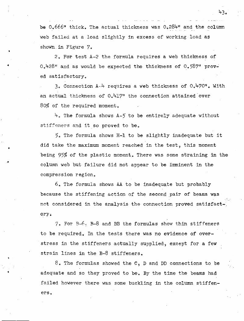
be 0,,666" thick" The actual thickness was 0 0 284u and the column
web failed at a load slightly in excess of working load as
shown in Figure 7"
2" For test A=2 the formula requires a web thickness of
0 0 428" and as would be expected the thickness of 0.5'8711 prov=
ed satisfactory"
3" Connection A=4 requires a web thickness of 0,,47011 • With
an actual thickness of 0 .. 417" the connection attained 'over
80% of the required moment o
4 u The formula shows A=5' to be entirely adequate without
stiffeners and it so proved to be"
5'0 The formula shows H-l to be slightly inadequate but it
did take the maximum moment reached in the test 9 this moment
being 95'% of the plastic moment" There was some straining in the
column web but failure did not appear to be imminent in the
compression region"
6" The formula shows AA to be inadequate but probably
because the stiffening action of the second pair of beams was
not considered in the analysis the connection proved satisfact-,
ory ..
'710 For B,=6~ B=8 and BB the formulas show thin stiffeners
to be required o In the tests there was no evidence of over=
stress in the stiffeners actually supplied 9 except for a few
strain lines in the B=8 stiffeners.
8. The formulas showed the C9 D and DD connections to be
adequate and so they proved to be. By the time the beams had
failed however there was some buckling in the column stiffen-
ers.,
Page 45
- I
TABLE ..2.
COMPARISON OF MODIFIED A"IoSoC. COMPRESS'ION REGION CRITERION
WITH CONNECTION TEST RESULTS.
Speci- bt k Req'd Hand- Meas- Req'd Actual Remarksmen book ured :'
in?w w w s s
in in in in in in
A-l- 2.99 0.812' 0.666 0.288 0.284 Column web buckled
A-2 2.99 1.312 0.428 0 0 575 0.587 Column we-b O.K.
A-4 2.99 1.188 0.470 0.390 0.417 Column web weak
A-5 2.99 1.500 0.378 0.580 0 0 580 Column web O.K•.._-........;.~--._.
B-6 2.99 0.812 0.288 0.284 0.25* 0.437 stiffened connect-ions-
B-8 2.99 1.125 0 0 294 0.300 0 0 25* 0.250 satisfactory
C-9 2.99 0.812 0 0 288 0.284 0.382 0.437 Connections O.K.but some stiffen-
C-l1- 2.99 1.125 0.294 0.300 0.34** 0.250 er buckling
D-12 2 0 99 1.125 0.294 0.39** 0.606 Connection O.K.
H;'l 2.99 0.812 0.666 0.600 Column web O.K. upto 0.95M when . -
, failure 8ccurred fri,,--
tension region of. connecti.on.---_..._---_. '1--"-" .. '_.~ ..._.~.._.....
i \
AA 3.02 1.188 0.474 0.390 0.395 Connection O.K.
BB 2.89 1.125 0 0 294 0.316 0 0 25* 0.5 Seat 4" aboveJlr.·compression flangeconnection. O.K.
DD 2 0 91 1.125 0.294 0 0 317 0.34** 0.6 Connection O.K.
Page 46
..
'.•
JiQies:* Determined by slenderness limitation, Equation (6)
** Determined by slenderness limitation, Equation (8)
*** Stiffening also included a plate perpendicular to
the seat - See Figure (15)0
45., '
Page 47
...
•
TABLE-Z
COMPARISON OF FORMULAs Qc.=...1y. w (t+ 7k) WITH COMPRESSION TESTS
Test Column Bar Column w k Computed TestThick- Web Qc Qcness Yields yin ksi . in in kip kip
E-l 12WF40 t 402 0 0 294 1.0125 99 102.5. .E-14 8WF48 t 3404 00 405 10063 110.1 137
E-15 8WF58 t 36.2 00 510 10188 162.6 202.5
E-16 10WF66 t 40.0 00 457 1 0 25 169.0 175.7
E-17 10WF72 t 35.0 00 510 1.313 173 190.', 18 12w"F65 . ' . 37.2 0.390 1 .. 188 129 143~- t
,
E-19 12WF85· t 37.8 Oe495 1 0 375 190 247.5
E-20 14wF61 t 36.2 0.. 378 1 0 25 127 137.5
E-21 ).4WF68 t 38.3 0.. 418 1 0 313 155 164
E-22 14wF84 t 39.3 0.451 1.375 180 221
E-23 14WF104 t 38~5 00495 10438 201 250
46.
Page 48
'.
w= bt-+3.5kt' o ••••• o.~ ••••••••••••••• (24)t+7k
is consistent when applied to the connection tests and to the
simplified tests" In the simplified tests of course 't. = 0..
However formulas (3) and (24) give very close results when ap
plied to practical connections, it being preferable to use (3)
since it is simpler o
2.2 Tension Regibn of Connection.
The only connection specimen in which the primary
cause of failure was in the tension region was test H-l where
Page 49
..
•
failure occurred at approximately 95% of the beam plastic moment.
The actual column flange thickness in this case was 0.43"
while that required by formula (13) is 0.69". Hence in this
case formula (13) appears conservative.
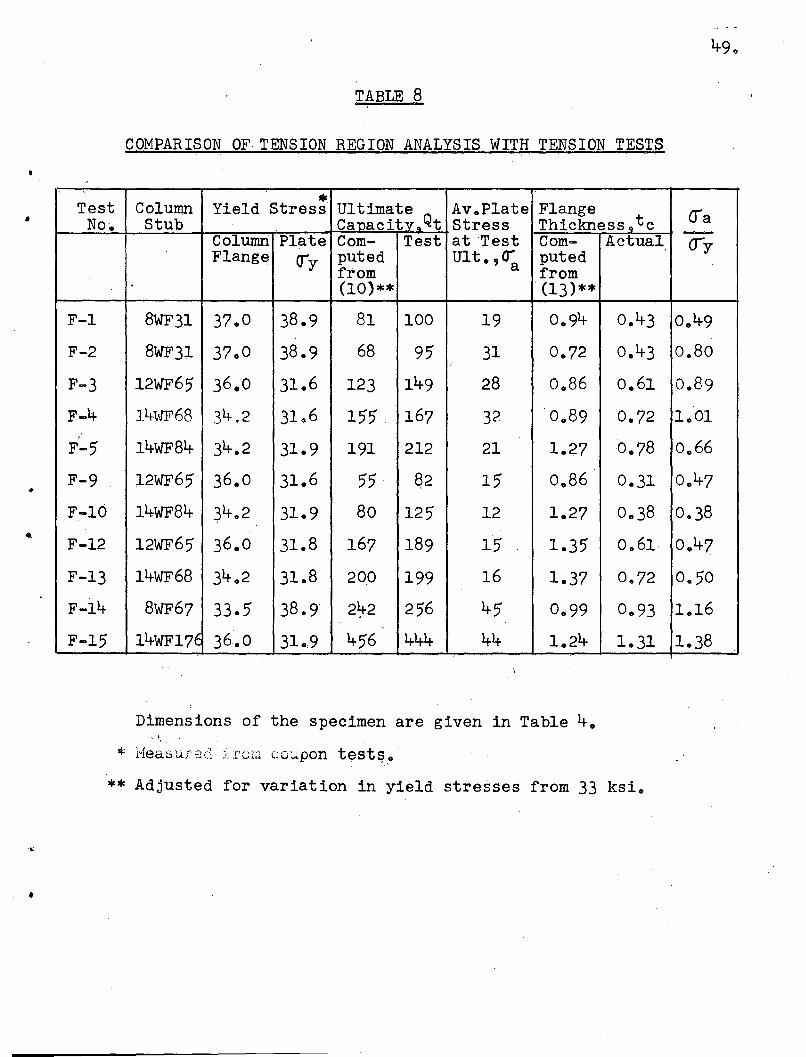
Table 8 compares the tension tests with the analysis by
means of two'methods ~ first through the ultimate capacity
equation (10) and then through the final design equation (13)~
The comparison with equation (10) shows conservatism in
all cases except test F-15. However in this case the plate was
strained into the strain hardening range and failure was pro
bably caused by shearing stresses at the ends of th~ weld due
to drawing down of the plate. A further indication of this is
that ~he weld failure began at one end of the weld. This type
of failure would not occur 1n an actual connection since the
beam flange is not stressed above yield stress.
The second comparison, between actual column flange thick-,
ness and that required by equation (13) is mainly of statis
tical interest. The last column shows the ratio of tension
plate stress at co~umn 'failure to tension plate yield stress
and illustrates that in all but three tests (F-4, F-14 and
F-15) the tens1.on plBrte was much stronger than would have
been sufficient to cause column failure at or prior to tension
plate yield. Consid~rable conservatism in equation (13) is
illustrated in the cases of F-4 and F-14. This is probably
due to the 20% conservatism introduced in equation (11)•
Page 50
•
TABLE 8
COMPARISON OF,TENSION REGION ANALYSIS WITH TENSION TESTS
Test Column Yield Stres: Ultimate Av.Plate Flange Q"'aNo'~ Stub Canacit:.v.Qt Stress Thickness 9
t c -Column Plate Com- Test atTest Com- Actual <JyFlange cry puted Ult. ,era puted
from from(10)** '(13)**
F-l 8WF31 37.0 38.9 81 100 19 0.94 0.43 0.49
F-2 8WF31 37.0 38.9 68 95 31 0.72 0.43 0.86
F-3 12WF65 36.0 31.6 123 149 28 0.86 0.61 0.89
F-4 14\VF68 34,.2 31.6 155 167 32 0 0 89 0.72 1 0 01,
14wF84 0.78 0.66F-5 34.2 31.9 191 212 21 1.27
F-9 12WF65 36.0 31.6 55 ~2 15 0.86 0.31 0.47
F-10 14-WF84 ~4.2 31.9 80 125 12 1.27 0.38 0.. 38
F-12 12WF65 36.0 31.8 167 189 15 1 .. 35 0.61· 0 ..47
F-13 14WF68 34 0 2 31.8 200 199 16 1 0 37 0.. 72 0.50
F-14 8WF67 33.5 38.9 2~2 256 45 0.99 0.93 1 .. 16
F-15 14WF17~ 36~0 31 0 9 456 444 44 1.24 1.31 1.38
Dimensions of the specimen are given in Table 4.".1,. '
* Measured frum co~pon tests~, ..
** Adjusted for variation in yield stresses from 33 ksi •
Page 51
•
•
3. ~imitations of This Investigation
The investigat~on has considered two and four-way con
nections in which every beam of the connection has been loaded
equally and gradually to failure. Detrimental effects could be
caused by:
(a) li.epetitiveLoading. A sufficient number of cycles of
loading and unloading could cause premature failure but this
is unlikely since much of the load in a building is de-ad load
and any variation would be of small magnitude.
(b) Unequal Loading of Opposing Beams. In this case shear
stresses ,,,ould be induced in the column web. However when the
beam loadings are approximately the same as would be the case
when beams of the same size framed into the column flanges
it wo~ld be expected that the above design formulas would be
valid. They would probably not be valid in the extreme case
of a beam framed into only one column flange. This problem is
one for further research.
(c) Wind Loading.This would tend to cause moments in the
same direction ~nd hence high shear stresses in the column Web.
As with (b) this is another problem for further research.
4. Advocated Design Methods.
There follow examples of connection design using the
proposed formulas.J
·4.1 Connection in Which no Stiffening is Required.
Consider a two-way connection in which l6WF50 beams
frame onto the flanges ofa l2WF99 column.From formula (3)
required w= btt+5k
Page 52
.'
Actual w = 0.580"
Hence no stiffening is needed in the compression region
of the connection.
From formula (13)
required \1;c = 0.4 {bt=0.842"
Actual t c = 0.921"
..
.'
Hence no stiffening is needed in the tension region of
the connE:lction. The computation for tension stiffening could
have been omitted by inspection of Figure 28 which shows that
the compression region of the connection for a l2WF99 is the
critical one regardless of beam dimensions.
4.2 Connection in Which Stiffening is ReqUired in
Compression Region Only.
Consider a two-way connection in which l6WF58 beams
frame onto the flanges of a 10WF89 column.
From formuJ.,a (3)
required w = 0.792"
But Actual w = 0.615"
Hence stiffening is required in the compression region
of the connection. The required size of horizontal plate stiff
eners is given by equations (5) and (6) •
From equation (5)
required s = bt - w (t + 5k)b
=0.144"
Page 53
But from equation (6)
s:> b l '
lb
> 0.25"
Hence in compression region of connection use tit horizon-
tal plate stiffeners, welded along three edges.
From formula (13)
required
But actual
t = 0.93411C
-.
Hence no stiffening is required in the tension region of
the connection,
4.3 Connection in Which Stiffening is Needed in Both
Tension and Compression Regions,
Consider a connection in which l8wF105 beams frame
onto the flanges of a l2WF65 column. Equations (3) and (13)
indicate that stiffeners are required in both the tension and
compression regions of the connection.
If horizontal plate stiffeners are to be used equation (5)
gives
s = 0.487"
which satisfies equation (6).
Hence use t" horizontal plate stiffeners in both tension
and compression regions of the connection.
If vertical plate stiffeners are to be used equation (7)
g;ives
required s = bt - wt+5k
=0.636"
'. : ...
Page 54
••
53.
From Equation (8)
s> dc- 30
= 0.4-05"
Hence use 11/16" vertical plate stiffeners flush with the
edges of the column flanges.
4-.4- Eccentric Stiffening.
Consider the same connection as in Section 4-.3 with,
in addition, two 16WF36 beams framing into opposite sides of
the web of the 12WF65 column. If the tension flanges of the
b~ams are at, the same level then the seating plates of the
16WF36 beams can be used as' stiffeners of approximately 2"
eccentricity for the 18WFI05 beams.
The required thickness, s, is given by equation (9);
s = l...2 [bt - w (t 5k~b
=0.828"
This satisfies equation (6)
Hence use 7/8" set;i.ting plates for the 16WF36 beams.
Page 55
,
•..
54.
APPENDIX
1. THEORETICAL ANALYSIS
1.1 Limiting Slenderness of Stiffeners.
The slenderness limits for the stiffeners are diffi-
cult to establish because -
(a) The restraint provided by welds at the ends of stiff-
eners is not known.
(b) The stress distributions in the stiffeners are not
The assumptions made in the following analysis probably
lead to conservative limits. The calculations for the limit-
ing slenderness of stiffeners are taken from formulas and fig
ures in reference 6•
Horizontal Stiffeners
Fixed __
x
5imp0 s()pported
freeThicKnes 5 ).s
SImply 5uppor fed
•
OCrAs shoWn in the Figure, consider the stiffener as fixed
along the edge welded to the column web and conservatively
assume it simply supported along the edges welded to the
column flanges.
Page 56
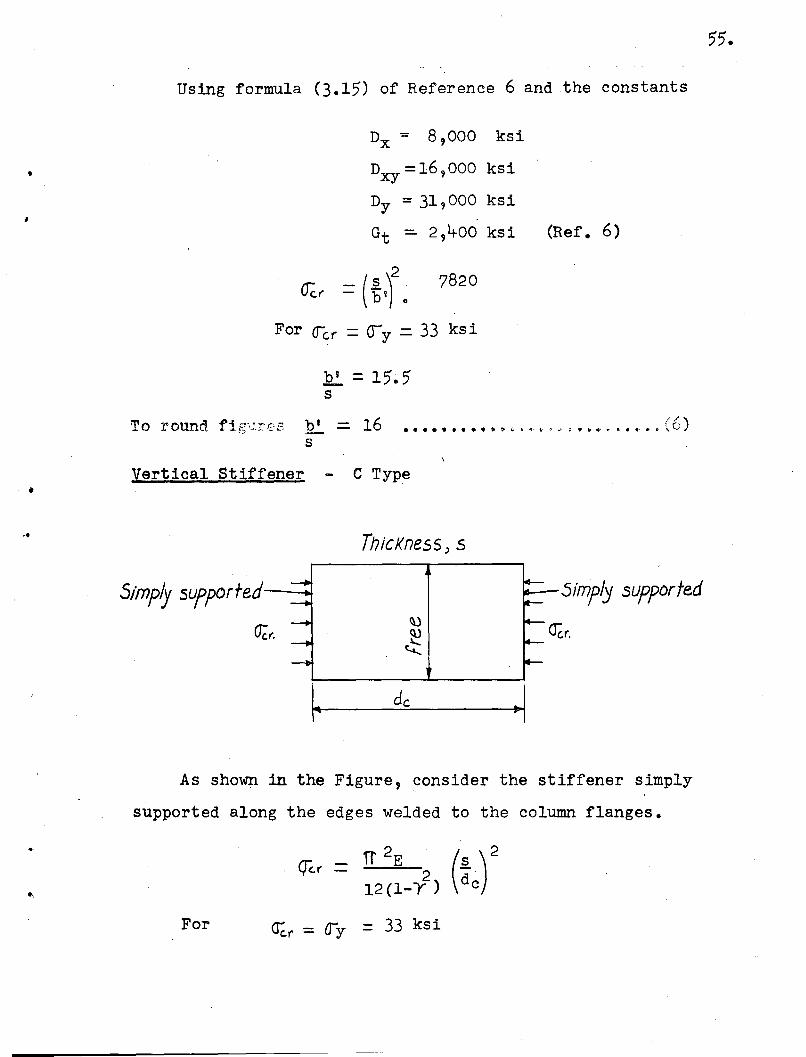
55.
Using formula (3.15) of Reference 6 and the constants
7820
•
Dx = 8,000 ksi
Dxy ~ 16,000 ksi
Dy = 31,000 ksi
Gt - 2,400 ksi (Ref. 6)
2~( = (~I) 0
For (fer = ()y - 33 ksi
To round fig';.J.r.ss .~ = 16 •••••••• , .. " •..,. , .' , •.•' (6)s
Vertical Stiffener - C Type
.,ThicKness) 5
5imply supportedSimply SUfPorfed
As shown in the. Figure, consider the stiffener simply
supported along the edges welded to the column flanges,
'IT 2E ()2Q(.I' = 2 ~l2(1-Y) d~
For <rc., = a-y = 33 ksi
Page 57
•
56.
dc 30 ., ., 0 • ., '(8)s
1.2 Rotation of Connections •
Examination of Figure 13 of Reference 4 shows that
the "hinge angle" or rotation at plastic moment required at
the ends of a fixed ended beam uniformly loaded along its
length, so that it will be able to form a mechanism? is given
by
or
H
H
e • e e e & • (I • II) 0 0 e • e is (18 )
Taking a practical case of a 16WF36 beam of span 24' the
required rotation is calculated to be
'. H= =37.2 x.IO radians
Here a particular case is taken but the above value of the
rotation will be greater than that required of most connections.
Considering a 12" gage length spanning across the column the
average rotation required across this length is 1.2 x 10⁻³
radians per inch. This value i~ plotted on all figures show-
ing connection rotation characteristics.
1.3 Elastic Distribution of stress on Column 'kG Line.
E. W. Parkes 5 developerr a theory giving the stress
distribution just inside the flange of a column· (in this case
the column 'k' line) for either a tension or compression load
ing on the flanges while the stresses are still in the elastic
range. For purposes of our case we will make the idealizations
Page 58
•
•
•
57.
that -
1. The load applied to the column flange can be consider
ed as a line load perpendicular to the column web •
2. The moment of inertia of the beam flange about th~
axis through its own centroid can be considered as infinite.
3. The distance between the column gk ' line and the cen
troid of the column flange can be considered as negligible
compared to the depth of the column.
4. As far as stress analysis is concerned the web of the
column can be considered as infinitely wide so that the stress
distribution at mid width is uniform.
Parkes analyzes the case mentioned above and also the
realistic case where the above idealizations do not apply. For
the case of all wide flange columns as used in practice however
the deviation in the elastic stress distribution between the
idealized and the realistic cases' is less than 5%. Being based
on the idealized case then the non dimensionalized curve as
drawn in Figure 27 represents to +5% the elastic stress dis
tribution along the column Ik 1 line for all wide flange shapes
.used in practice. The scale of Figure 27 has been made so that
thB area beneath this curve represents the ultimate load as
obtained from tests. For purposes of plotting this figure
Parkes used the non dimensionalizing parameters ~o and ~o
which were functions of the column dimensions o The curve, of
course, is not the stress distribution at failure since yield
ing will have taken place. However by the use of the appro
priate vertical scale factor this curve will represent, the
stress distribution until, the first yielding occurs.
Page 59
•
..
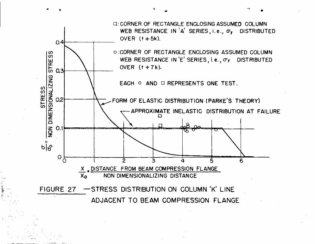
1,4 Probab~e Inelastic Distribution of stress on ColUmn
Ik l Line.
The area under the elastic curve discussed above can be
compared with the assumed resistance offered by the column web
in the development of the compression criterion in Section C,
This resistance is represented by the corners of the rectangle
in Figure 27 which show yield point stress distributed over a
distance (t +5k) for the I A' Series Tests and over a distance
(t+7k) for the lEI Series Tests,
As illustrated in the figure it does so happen that the
non dimensionalizing stress, ~o , as used by Parkes causes the
ratio ~y/~o to have values very close to 0,1 for all the spec
imens tested except the column section 12WF65 as used in test
A-4~ Hence the actual inelastic stres~ distribution at failure
for all the test cases except A-4 is represented closely by the
plot on Figure 27 which includes the horizontal line at yield
stress re~resenting the inelastic resistance and the oblique
line representing the elastic resistance. Since the area under
this curve is greater than the area under the curves represent
ing the assumed resistance of the column webs then the assumpt
ion of a distribution of yield stress over a distance of (t + 5k)
or (t+7k) as the case may be is conservative.
It is also interesting to note the stress distribution at
various stages of loading. In the elastic stages of the tests,
the distribution of stress is similar to that shown by the
elastic curve. After a little yielding has occurred, a plat
eau will develop at yield stress. This plateau will become
wider as the load increases until at failure the distribution
Page 60
•
59.
is as shown.
1.5' Alte:cna-cive Design Formulas For Compression Region
of Connections
The Modified A.I.S.C. method of design has been describ
ed in Section C. Two other approaches are however worthy of note :
1.51 Plastic Analysis Approach,
This approach assumes a stress distribution in the
beam, loaded to its capacity Mp7 as shown by Section a-a in
Figure 26. The corresponding stress distribution in the column
web at the ,end of the flange-to-web fillet is shown by Section• '<
b-b. This procedure results in the following analysis -
(a) Unstiffened Columns. (Series A). Assume the beam is
developing its plastic moment, Mp• For the compression flange
the pressure against the column will be approximately as· shown
in Figure 26.
Then
and
Qb =.. Ab(Jy"2
Qw = cry w [g +3kJ
•
If the compression region of the connection is' just satis~
factory without stiffeners'.'
or <ry w (~+3k)= ~ba-y (20)
therefore w = Ab ••••••••••••••••• {2l)d+6k
(b) Columns with Horizontal Plate Stiffeners (Series B).
The presence of the stiffeners modifies equation (20) to
Page 61
s is again subject to the limitation that s>b u as shown-Ib
s b
..
therefore
~b cry = cTy w [g +31 0- y.
s: ~b [Ab = (d+6k~ w ................... (;22)
60.
'.
in Part 1 of the Appendix ..
(c) Columns with Vertical Stiffeners (Series C and D). The
presence of the stiffeners modifies equation (21) to
Qb = Qc + Qs
Since the stiffener plate is at the edge of the flange it
will not be as effective in resisting the beam compression as
is the column web. Strain readings on web and stiffener indicate
that the stresses in the stiffeners are approximately one half
those in the web.
Assuming the latter
Qs = 2(J"yS (t+6k)2"
therefore,
Hence ~b cry =-
s=
cry w <g + 3k)+ (J"'y s
1[Ab"=W £d + 6kl12 - t+ k J
(t+ 6k)
o • e OJ 0 • 0 0 • 0 0 (.23)
The stiffener thickness is again restricted by the in-
equality, s> dc-- .30
" .'....
1.52 Modified Plastic Analysis Approach
The preceding analysis assumes that at failure a
length of (d + 3k) of web is at yield stress (See Figure 26).2
However in most connections the beam web is thinner than the
column web so that near the horizontal centerline of the con-
Page 62
61.
nection where tpe effect of the beam flange force is negligible
the colullln web merely resists the beam web force and·so is not
at yield stres$.
If we assume as we have done in the Series E tests and
as shown in Figure 26 that the length Of column web effective
in resisting the beam flange force is (t+7k) and that the beam
web force outside this region is resisted by the column web
immediately adjacent to it then equilibrium over the length
of(t +- 7k) gives
(a) Unstiffened Connection.
bt <ry + t,l. 2k (j = w lJ (t -j-7k)2 y y
or w bt~3.5 kt' •••••••••••• (24)t+7k
..~By going through an analogous procedure as that in
Section C we have the results
(b) Horizontal Plate Stiffeners.
s - t [bt+ 3. 5 kt' = w (t+7k~ ... 0 0 eo •• 0 •• (25)
where s is again sUbject to the limitation that s;> b l
-Ib
(c) I~~~ct:icaJ. Plate Stiffeners •
o· where
s = bt + 30 5 kt ' - wt+7k
s > dc- 30
••• e.ooeee •••••••••••• (26)
Table 9 compares the results of these two methods with
the Modified AoloSoC o Approach for the connections tested.
Page 63
..
,
..
-.
TABLE 9
COMPARISON OF THE THREE COMPRESSION SIDE CRITERIA
Speci Web Thiclmess 9 w Stiffener Thickness 9 s Remarks-men
Mod. Plas- MOd. Act= -Modo Plas= Mod" Act=AISC tic ' Plas- ual AISC tic P1as- ual
tic tic
A-I 0.666 0.504 0.624 0.284 Col.web buckled
A-2 0.428 0.440 0,,450 0.587 Col!,web O"K.
A-4 0.470 0.453 0.480 0,,417 Col.web weak.A-5 0.378 0.420 0.412 0.580 Col.web OoK o
*B-6
, , -- 0.25 0,,326 0 0 297 0.437 Stiffened. ,-
* * connectionsB-8 0.25 0 0 261 0.25 0.250 satisfactory,
C-9 0 0 382 0.,429 0.340 0,,437 Connections OoK"** ** ** but some
C-ll 0.34 ~.39 0 0 34 ~,,250 stiffenerbuckling
** ** **D.~12 0 .. 34 0 0 34 0 0 34 0 .. 606 Connection O.. K.
- H-l 0.666 0.504 0.624 0 0 600 ' Col. web O.K.up to a.95M
.---1--~-.-.-when failur~occurred in
, tension regionof connection
---- , '~--
AA 0.474 0.445 0.479 0.395 ,/ Connection O.K.* * *BB 0 0 25 0 0 25 0,,25 0.5 Seat 4" above***
compressionflange~ Connect-ion O~K~,:-::_-
** ** **DD 0.34· 0 .. 34- 0 .. 34 0 0 6 Connection O.K.,
Page 64
..
...
Note§)
* Determined by slenderness limitations 9 Equation (6).
** Determined by slenderness limitations 9 Equation (8) •
*** Stiffening also included a plate perpendicular to
the seat = see Figure 15.
1.6 Analysis of Tension Region of Connection.
Figure A illustrates the action of the column flange
in the tension region of the connection. The column flange can
be constdered as acting as two plates both of type ABeD. The
beam. flange< i::: :3sumed to place a line J..,x, -"1 u::'l Ucich 'JJ:' th8's(:1
plates. The effective length of the plates are assumed to be.
l2t c and the plates are assumed to be fixed at the ends of this
length. The plate is also assumed to be fixed adjacent to the7
column web. Analysis of this plate by means of yield line theory
leads to the result that the ultimate capacity of this plate is
where
and n
Pu2- cl cry t c
cl - Jtjf3+ 8/772 _. = -"/,A
8/~ [ Jt3' +--c8 A. -8Jf3 - p/q (refer to figure A)
)...=. l/q (refer to figure A)
For the wide flange columns and beams used in practical
connections 9 it has been found that cl varies within the range
3.5 to 5.
As a conservative approximation 9 take cl = 3.50
Page 65
•
..
I
II
I I--+im~
I I
I II II , J
I IrzzzzzONZ4?/ZZZ77/~1 .L b I I "~I II .'.
t+---~- be ·------....
COLUMN fLANGE
Central RigId Portion. i'.. ".'
~
.l,c:::.====±::""-::::t====::::::r
1m' DI5TANCE!m : W t 2. (K-tc)
fA.
Line Load
. Free
9=~-r:0. - J2... _ IlL,{,-z 2
P = /2 tc.
CONSIDERED PLATE<1 ITS LOADING
D~ti~C _Flx.ed. ,J '. ,FIGURE A.
\
,..
Page 66
Hence cap,city of two plates is given by
Force carried by central rigid portion
65.
..
Hence
- cry t m
. +".. 2o-y t m 7v y t c
Page 67
..
•
#,
2. APPENDIX TO TWO-WAY TESTS.
2,.1 Summary of Coupon Tests •
. -Section Mark E G"'pL O"uy O"'yL lfuit est
ksi ksi ksi ksi' ksi in/in
'7/16"plate 59E/8/3 t 35.6 34.8 59.2.' '-2
30·,000 - 1.5 x 10. -.
59E/5/3 t 29,500 - 35.8 34.2 59.6 -59E/2/3 t 30,200 - 35~6 34.6 60.0 -
1/2" plate 68E/6/3 t 30,000 - 33.1 32.1 56.0 -5/1611plat f;3 48'/9/3 t 29,900 - 38.2 37.2 62.5 -
48 /3/3 t 31,700 - 38.2 37.8 61.3 -.i . l II ' ,
1/2" plate 68E/6/1 c .29,800 24.1 32.8 - - -68E/6/2 c. 30,600 26.7 33.6 - - -
12WF40 38G/l tf 35.2 36.9 37.3 62.0 1.66x 10~2
38G/ 2 tf 34.3 36.3 36.5 61.7 1.7
38G/3- tw . 42.8 44.0 42.8 65.4 2.02
38G/4 tf ~6.6 38.3- 37.6 61.9 1.9
8WF31 54E31/1tf 34.7 39.4 37.8 63.4 1.72
54E31/2'4f 36.3 - 38.1 63.0 1.94
54E31/3tw 35.4 39.'7 38.3 63.0 1.98
16WF36 53E939/1tf 33.5 40 ..8 40.0 61.7 2,,16
53E939/2tf 38.2 - 39.5 61'.8 2.22
53E939/3tw 41.4 43.5 42.7 64.5 2.17.53E939/4tf - 39.6 39.2 61.2 1.94
8WF67 54E67~ tf - 32.4 32.2 61.4 1.18
54E67/2 tf 28.5 35.2 34.6 61.9 1.25
54E67/3 tw - 38,.8 37.7 60.6 1.94. 54E67/4 tf - 34.1. 33.2 61.3- 1.44
Page 68
,.
•
."
.' .
Summary of Coupon Tests. ( Cont'd.l
. ,. , . .
CT"pL O"uy o-yt O""ult " 6 stSection Mark Eksi ksi ksi ksi ksi in/iil
"
12WF99 55E/2 tf 31.3 34.6 34.5 62.5 1.31
55E/4. tf 34.3 36.7 35.8 63.7 1.41'
12WF65 42E/1 tf - 37.2 36.4- 62.0 1.61
. 42E/~ tf - 36.4- 36.1 62.1 1.55
'42E/3 tw - 40.6 38.8 61.5 1.43
42E/4 ·tf - 37.1 36.1 62.2 1.48
liot~1?Z
,For WFmembers E is in range 25,000 <E < 30,000 ksi.
c.= compress1on coupon
tf = tension. flange co~pon
tw = tension web coupon•
67.
Page 69
I
'"
68.--
2.2 Calculations for Design of Specimen:
Columns
Assume L = 72r
Then from A.I.S.C',- Manual
P= 17,000 - 0.405A
Column Working Stress = 1~.'5 ksi
Structural Section Details
Column Area tt* Area as Pw kips 1.65 Pw 2xPw trestNo.,Size measured
8WF3l 9.12 9.01 132 218 264 Al,B6,C9
8WF67 19.70 19.94 286 -_ .. 472 572 A2
l2WF40 '11.77 11.31 171 283 3lt4 B8,Cll,D12
l2WF65 19.11 18.66 278 459 550 A4
**l2WF99 29!.Q9 28.45 422 696 BOOk A5
* A.I.S.C. Handbook Value.
** Testing Machine capacity = 800k
Analysis of Beams and Beam-tlolumn Flange Welds:
All d:'u;,"cnsion of sections as measured on specimens
,,-
Beams: 16WF36
Bending: -
l\r = r:rwS = VwL
<Jw = 20ksi
O"wS-L
20x56•4 =23.5 kips -48 use 24kips
Vy= 'J"yS, o-y (avg. for l6WF36) = 39.6 ks!L
Vy= 39.6 x 56.4 = 46.5 kips48
Page 70
.,
Vu = (fyZ , Z = plastic modulusL
= 39.6 x 63.76 = 52.5 kips48
Elastic Analysis of Welds at Working Beam Load:,-
Design butt welds to carry applied moment, and fillet weld
to carry applied shear.
MW = 24 x 48 k" , d = 15.91 - 0.43 = 15.48ftw " '"
24 x 48 = 74.5 kips- 1;.48
(OK)2.4 kips/in\ '
q - V -24 -'0.922 kin-rr-2'b-fillet) = 9.6n = 9.6 x 1 =
, ' "~
I/
qallow
F '~ - 24 4 ksi> 20ksi (ov~rstressed)(j':= VI ::: 7 09 0' 431' - .'
Wel~ Area ,., x. ,', .
Vw = 24 k
Length of weldS =26",
Try 1/4" fillet weld
•
'f'
Shear:
13 • (0.29) 15~91
~ 60 k /'" 24 k (OK)
Influence of shear on Vu may be neglected if
Page 71
(14.94)(0.29)1.732 .
2.5
Vu~ ~ Aw
Z < AwL -{3
~<1.33 < (OK)
70.
Lateral Buckling:
(in the elastic range)
whence 5'allow
1& = 96 x 15.~1 =500 <600 (OK)bt 7.09 x O. 31
. 20 ksi
Local Buckling: elastic range - See Clause l8(b) of A.I.S.C.
spec.
..
Actual 12. =- ~ = 16.45<32t ~
. (6)To reach strain hardening 12. ~ 17
t
(OK)
Therefore beams critical for local flange buckling in
plastic .range.(6)
To reach strain hardening d ~55w -.
g, -:- 15.91 = 54.8w 0.29
for web
Therefore beams critical for local buckling in plastic
range.
Deflections: ~elastic ~ VL3 - assuming complete restraint.3EI
~y = V L3 . Vy = 46.5 kipsJ::-3EI L 48"
E - 30 x 103 ksi
I - 448.96 in4
= 46.5' (48)33x 30 x 103 x 448.96
Page 72
~ult.
= 0.127"
= .~ x 0.127 = 0.144" assuming idealized r .,::;
(j - e and M - ¢ relationship.
In nondimensional form:
At yield V V
y-
1 = ~~y
•
1
,.
At ultimate Vu = ~ = 1.13 = ~uvy 1+03 dY
Beam Rotations:
The rotation of the beam can be expressed as a change in
slope of tho'?; p(jj.r i; ,of load application with respect to the
. connection assuming the latter to develop complete restraint.
Applying the moment area theorem:
. ., 2. eend = ..\l L VL = VL. '2 EI 2EI
Therefore eyfeld= VyL2
and V = 2EI. g2EI y L2 Y
But V - 3EI ~yyL2
Therefore 9y - 3EI J • L2
.3. J~L2 Y ill 2L
0.031 [ radiansy
Page 73
2.3 Material Dimensions and Properties
•F---..--.....~---.J-. -
72, •.- average values
I
l6WF36 Ibeam
" r"0-48S 0-377
/5'-s/"
tapered flanges
8WF3:l1 (A-l)Column (B-6)
(C-9)
parallel flanges.
~I (A-2)'COIWDn
- ... 0-284"
fa-SIII/"
I
~----,---t I8-36" --t
8-08"
parallel, flanges
,,-,\,
Page 74
12WF:22:1 (A-4)Column
73.
r--..L-~----.., -.-I
f0·594"
I
l2WF99: (A!"'5') .Column
12'/3"parallel flangeS
I~12·00"
0·5"80"
~I
parallel flanges
12'80"
l2WF4o: (B-8)Column (C-ll) t
0·438"
parallel flanges
1/-9 ':
(7/16)(1/4)(5'/16)
'lPlate thickness:
B-6B-8c-91C-liJ
\.-- B·OS"
average valuesa4
- from coupon and measure-ments on specimens
b = 3.9u
b = 3.9"d =. 22 ft
Page 75
. ·r
2.4 Section Properties.
16WF36 Beams8- .. ,
~ = (3.4) (.377)
.108 (3.4)2
'(.145)(7.96)
A
2Ixx =(1.283)(7.766)2T (0.1&4) (7.542)3'
(0,145') (7,955)12
(1.155)(3,978)2
Ixx
S =Ixx = 4-i.t8,*6 = 56.4 in. 3c 7.9. 5
'.
Z = (1.283)(7.766)It (0.181+) (7.542)
(1.155) (3.~978)
z
y = 1..2....9!± - 6.08-. "2:b22
Y = 7.96 11
o -6 08n
=~n
=1.283
= 0.184
=1 155"2:b22
=10.48~' 7·9$"S·
- 77.40- 10~4.6 ~---
6.11
=. 18.24. 112 0 2
= 44~.9.6 ~4
= 9,'96=1 0 39
=1&:~= 63,76 in.3
t
',-. ~.
...~~. .-
8WF31 Column:
8WF67 Column:
l2WF65 Column:
12WF99 Column:
A = (2)(0.430)(8.09)(7.22)(0.284)·
A = (2)(0.941)(8.36)(7.148) (0.587)
A = (2)(.594)(11.88)(10.942) (0.417)'
A = (2)(0.921)(12)(10.958 ) (0. 58 )
- 6.96- g....Q2
9.01 c "
=- 15.75=~. ~an
- 14.10
- l~:g~on
= 22.10=. ~'~a"
Page 76
=- 8~03= 3~28
11.31 0 n
75.
"
3. Appendix To Four=way Tests.
3.1 Summary of Coupon Tests.
'1Section Mark E 6'uy i 6y1 Dst y,6u1t. Est
I Ksi, Ksi i Ksi Ksi Ksi inA/in.I .
1/4"P1ate 233/P , 30,900 40.65 39.87 62.00 0.01725. 25,100 41.02 39.74 61.54 0.01775i I
12WF65 233/Wl 30,400 42.57 41.81 67.74 0.015233/Wl, 29,700' 38.37 38.54 67.74 0.00675233/F1 30,100 40.63 40.07 65.5710.01875233/Fl 30,600 44.28 40.46 64.8~ 0.200
, ,, I '
12WF40 i233/W2' 31,200 47.17 44.16 39.85 68.93 0.021233/W·2 30,700 50.00 48.86 43.60 70.87233/F2 1 31,300'43.47 41.77 37.86 68.00 0.0175233/F2 29,400 42.90 41.51 37.67 68.45 0.01875
16WF36 233/W3 29,500 50.58 48.95 63.63,233/W3 30,600 47.00 45.66 61.64'233/F3 30,400 41.86 40.25 61.18 0.0185233/F3 30,200 40.58 38.98 59.99 0.0215
12WF27 233/W4 31,200 43.70 43.70 38.81 :61.62233/W431,100 45.14 41.89 37.83161.02233/F4
1
31 ,100 40. 36
1
38.65 34.74161.24 00 0175233/F429,800 39.36 38.17 33.79 FO•03 0.02075
Notes:
W Web
F Flange
Page 77
3~? Calculations for Design of Specimens
ColUmns:
"
As in Section 2 0 2 of Appendix
Column Working Stress = 14 0 5' ksi
Structural Section Detailsg
--5'5'2 i
340
334
:s-C-p~-11.651'wI2PwIred •.
----,---
1 27614 5'5'
'170280
1671 276<~~.~~ ..="-~-
I'Cest· Colman'-Ii
._..."".,..-~..
AiWea in2* Area
. Size measu
IAA l2WF65' ' 19.11 19 0 00Ii
112WF4?
I
BB 11 0 77 11.70
DD l12WF40 11 0 77 11 0 49.. . .. - ,
.'.
* A.loS.C. Handbook Value
Analysis of Beams and Beam-Column Flange Welds:
All dimensions of sections as measured on specimens
6w =20 ksi
Bending:
6 Sw
VY
(i S
-+6 z+
Z : plastic modulus
The calculations are s;~i1ar to those in Section 2 of this
Appendix. Lateral Buckling 9 local buckling, shear, deflections
and beam rotations were investigated and calculations are
similar to those found in Section 2.
Page 78
,.
77.
Al1aly~!s pf_~elds for Specimen BB
l2WF27 Beamsg
Use working load and allowable working stresses for the
design of welds 9 seat 9 stiffener 9 etc ••••• ; then check for
ultimate load ..
v = 19 kipswT = C 684 = ,7 .. 2 kips
11 .. 95Spe'h section (26h) A" I oS "C .. 8
R = 24 ksit~n+k)
19 x 36 =684 in-kips
Required plate thickness -
,f
n = 19 - 4 .. 68 =- 2 .. , inches required bearing length,.75
From Table 2, in the AoreS.C. text of structural Shop
Drafting Vol .. 2, the choice isg
4" wide seat; 1/4" Fillet Welds; L = 7"
Plate Thickness 1/2"
Top Plate Weld Designg
20 x 9.75At ultimate load the unit stress will be 125 - i+2~7 kips
0.3 x 9.75Use 1/2" Plate
r··.. ·The length of weld available is 9 .. 7' + 2 x 3.75 = 17.25"
Using butt welds on the plate
7.. 25 k/in
2£29-,,IXI72
.~
l7:25'
14500 psi. This is ~K.
Page 79
78.
Weld connecting ~op Plate to Beam Fianges&
The fillet ~elds are limited to 3/8" size.
Working stress for 3/8" fillets is 3600 pounds/in.
Using the factor of safety of 3 9 we use for design
3 x 3600
10,800 /h/m
Required length of weld
125,10
12.5 in
Length of weld available = 6" overhead fillets.6 - 1/2" fillet
on· 'cop of flange.
Check on Tee Seats
From Grover's ~Manual of Design for Ar·cWelded Steel structures",
page 1232
11 = 2~.04 DL~L +16e
21
18.3 kips
L =. 8"D =*R = U.04 x tb x 64
AI 2''V64 + 16(3.2)ultimate R =3 x 18.3 = 54.9 K
where
Predicted
This is:''1 i;ly excess of 41.4 9 the prGciiuted ultimate load.
3.3 Material Dimensions and Properties.
In the figure below the average values of all the
dimensions of the WF sections used in the tests is shown. The
calculations of the section properties are similar to that
presented in Section 2 of the Appendix. In the Table below the
Page 80
•
different section properties are shown:
SECTION PROPERTIES
-~est lBe~~-s-~z~~ Area 1Section M~~~lus-I-Plastic MOdU1~S
AA II 16WF36 1110 028\ 55,,59 Ii. 62.73r .
BB 16WF36 Ii 10 029 54020 61 .. 5212WF27 Ii 7.83 32.60 36 056
Ii
DD 16.WF36 110.24 54006 61.37I'
79.
Page 81
~ 12" ~
12W6S
~ 7-03" ~16W"36
0·478" 0,348"
TEST BB
0·5IS"... \-_. ... ---L-,·_·····--r-r-
0·426" 0·32
.•• _ y_'_ . ~_._.,J.. __ J._--. .._-+
1/·92"
12V1F40
14 6'$5''' ~\0·48'" 12 '1/1/"27
/6 W'.36
0·316"
TEST DD12·0" /5-836"
0'317" 0·2..96"
WF SECTIONS 9 ACTUAL DIMENSIONS
FQUR-WAY CONNECTIONS
'l
.,
~r----::8;:---;:'0 ..~~/2V1F40 re 7-0" ~
16~36
Page 82
FIGURE 1 - GENERAL VIEW OF TWO-WAY TEST IN PROGRESS.
Page 83
•. JACK
'f
..
DYNAMOMETER."--.-- '.".
SYMMETRICAL ABOUT CENTERLINE,
, ENLARGED DETAILOF BUTT WELD
=<D
-'~
8WF31
8WF67
.12WF40
12WF65
COLUMNS:
- '. -.- 12" , 12 (IILAIERAL SUPPO RT To~"-------,,,,,w+--~'----+-~~fo'='+~H4"""""--+'-'~-
!COMPRESSION FLANGE 'ROTATION BARS! 4 1_0"r--
FIGURE ORIENTED TO SHOW CONNECTION
AS FOUND IN CONSTRUCTION..
. 12WF99
.'
, FIGURE 2, ' TEST AR.RJ..NGEMENT -- ':WO·WAY CONNECTIONS- ,. --".. ~ ._--_.-.... ...- ...
Page 84
..
L~_--i~==B 8 f3-=--(f
IIII
I!
II I,I
ilS~ ~,. . .__,1 ~---_ .. -.
lJ--JJ
~
----
~, ~
L II~-
I
I
~ J
)( ,'
I'"
,......
( '" 7 \
I
II
")-
J
SERIES A
NO COLUMNSTIFFENERS
SERIES BHORIZONTAL PLATE
STIFFENERS
SERIES C .,
VERTICAL PLATE.STIFFENERS
SE:RiES DSPUT WF
STIFFENERS
FIGURE 3 - THE A,B,C,D SERIES OF TWO-WAY BEAM COLUMN CONNECTIONS
Page 85
\I
I
t----------- fC=.=========ltt ~ - - - - - -- --j
"....-- - -/ - -
I ~ ~ "I I~ ./
~ '"~
,/./
'"~V
./
./
~//
/ ./
I '" ./ \'" /
.., 1/ ./ ...1/~ ./
1//
1/ ;./
SERIES H DOUBLER PLATE STIFFENERS
FIGURE 4 - THE TEST SERIES OF TWO~ WAY BEAM,~,
COLUMN CONNEC TIONS (CONTINUED)
Page 86
.A-I
'- . ._.J§.§l_
=== =-== :::.= == i:ilII == -
r
I.I
' ....
I I ·A-I-_..-. -----~_..Itr___,;;~ -. --Ja--.-------.-----------,
+ " /
t~-.'- IlIIiII -- .._.- .-- ._- --- -J---- .- -------
t___~ ----B!ll _
I '.
PLAN
REP EAr Sf< .4::::' A (; ESAS SHOWNOhlTOP PLATE
FIGURE 5 - INSTRUMENTATION PLAN-SERIES B
~-~:-._~
I I~~\ Ii I I I' " Ij f I \ ,I I' I
--" I' '/'. I .. -\--- +II \ ;
I Ii i iI Ii \ ;: : J"", ' ;!; I r " .:: J: ,;
I I !i \:,.1-- J l . \i--------.------.r
I
L--.----Jl ...
Page 87
~.
•
-A-2 "7 I
'-+-'Pt--+-~_B~6_'~__~~_... _
ULTIMATE: LOAD'Vu/V'II
,WORKING LOAD. !}=.{! c-=r8t==:J I =:l8J:-u-.=JVw2i"f~L
~-"'-l_____ P _ __._oJ
.. .. -..--t- P-2V P-2V P-2V P-2V. .i
r,
I - r111 .
I,V Vi V l' V v·
v. iML VI
-L ~~F.,.- I~l II..~
.A·' r O o·.....,..). - 1 " _. ~
p. p' p P.
THEORETICALCURVE.
0.25
o'--------l-:IO-----2.....1.0------3.1-0-----4...J..O------SI.-O-----J
. BEAM DEFLECTION, d/dy
'2'<t:
LUco .!
I 00 "--t--f{ff-------"+--~--y-1ELD POINT LOA.D.._71L..-__~""'__-. . 1---
~ I>~
1ci I O_751Ht--+-------+-.~-----L----<'
,0, --l
Page 88
C-9 D~12
FIGURE 7 - PHOTOGRAPHS OF TESTS A-Is B~89 C-9 AND D~12.
B-8
A-I
Page 89
-..
'. <:::QLYMN. WEB,
ROTATION
'H'=ROT'N. REO'D. AT Mp
OY_ERALI ROTATION.
.0.00/
A-4
- I .VYORKING ~OAD ON BEAM 7- --.. ._-... -- - - --~-
MOMENT - ROTATION OF BEAM BASED ON ~ ,~~ 36 ksi.. _., -.' ... -. -- .. _. -- .. .~ -. '.' .
,A-5....
·A-.Z.
OVERALL ROTATION "r ' I ..
, END Of USABLE DATA---_.. .. _..• --.. -0.- • _ . oJ.
COLl/MN WE~ __,-~OVERALL ROTATION ,
I ' ITHEORETICAL ULriMA IE- BEAM MOMENT - Mp
~o~~~~~~~~~~~~~~~~~.~ _~~ ~~ ~~2
. .1 ' I .
s==_nt-o~_ET_IC_AL FIRS_T_Y~E_LD~G-5?~._TH~~~~~;~ _
OVERALL '
-:,... .-
}QQQ-
;500
, ,
1000 h-'--p.-tl'---HD----~---__++_I__---__+_---__+_---___I
,2
V1UJ6 2000 H----+...lf~--+_t-k+--~!__--_+_----'~~~~O:::::::"'-~---~---__i~---___l
Z I COLUMN W~-B'_
II ,ROTATION
-....+- --...-.++-_.:..:'------ ,-
c... '::x:
.:' 500' r+------~ ;
ZUJ
~o2
RADIANS
o~ L.-..__---.lL...-__.--I ---J.P~-=E:.:..R~tN.:.:C:...:.H..:......L. ---l..- _
_. .
SERIES A
. ,ANGULAR ROTATION, - ' RADIANS
. . ..
,FiGURE 8 -COMPARISON OF COLUMN WEB AND CONNECTION ROTATIONCHARACTERISTICS WITH THAT FOR THE BEAM I SERIES A
Page 90
.....
V') ,
UJI
'UZ.a..:::.:::
I
:2I.
I1~'C-9
II~C-li V D- 12
SERIES B, C &D500 13----~--__+---__4I~--___4---__+f_---_+_---_r__---,__--_____1
b.QO!~Idr---
RADIANSPER INCHO'-------IL----.J.-__--L -J.. -L- ....L..- ...L- ~____l
ANGULAR ROTATlON -RADIANS PER INCH
FIGURE 9 - COMPARISON OF COLUMN WEB AND CONNECTION ROTATION
CHARACTERISTICS WITH THAT FOR THE BEAM~SERIES B,C,8D
Page 91
'. ..'~,
98723456ANGULAR ROTATION-RADIANS PER INCH
FIGURE 10- COMPARISON OF COLUMN WEB AND CONNECTION ROTATION
CHARACTERISTICS WITH THAT FOR THE BEAM ~ SERI ES H
I IEND OF USABLE DATA_____ ~,_______~L _____ _BEA~ ~ASTI2 MQ~ENTL~_ -- ----1------
- ..n:iD ,- '. I'~~ , - n
/' ~TH!:~ETICA.!:J 1R.2L Y'~Ll,!NG.2i ~MY:~--f-,'-- -"l> ------
loA:
ift OVERALL'H', L ,I
, r ICOLUMN WEB 'Him ROT'N. RE010 AT MDI
~t-THEORETICAL1
BEAM ROTATION OVERALL COLUMNROTATION VW~B
Ie BEAM WORKING MOMENT ~rt ----- - ----..... ---------.-:..-. ----- ..... '" /
jI h..0 0.001, \ /I , \
, I
~1 RADIANS \ \ I 1!~
~RINCH I -__a
SERIES H
• 1oo
3000
500
2500
~2000::I:<.)Z
a..~ 1500
·2I.....
ZLLJ
~ 1000::E
'.
Page 92
I'
.'
,i '
STRESS DISTRIBUTION ... '
TFNSIOI'J FLAt'.!GE C()~v1PR tSSiOt'·J h.ANGE
! '
y.p.
··..:_··--.:...-.1
!-,,
Vw"-" 1:5 VW !;-')1")1i I Q
I b ,J j·r--·--------"--------~·· " _ .., 20 hi y.~'.'
a
iVW, r'1..:=.:...:q··
, \I .~I J
I l.---~_..- .!o
y.p.
v·p·
·-···--1I
20 ksi
Vw 1.5Vw' I.. --...._-- --" ....- ... _._._ .. __:---_.__.__.....-{
,P I r.o: - 'tl. r---r-.J
:)
~ - .- -'- ----_. - ,---.-.. ~ .._- _--_._._--_.- .
DETLF< r\.~ i I~ El)
FRO~v1 /,,,
~·----l ~---'-"--"'-"---'
,..... '___o __J )\ .... ' Ir----:---} .=I, l. d j
Ill!Ili'1t'l -{J J\' i Lr------~----'
£.-;\"If-3 !
Vvi ~ I 1.5Vw Ir~---'-'- -- -- ·-t-a< . ---·----1
I 1< II ~ ! II " 6 I c, I1----....- .. -- i .'- - :a 20 ksi . y,p~
,._..__. .1y.p..
,Vw"" I 1.5Vwi~----..-·--1-------:-1
I
r--------a ~o ksi
n.r-.--·-i L"\ IlI.B , I) '" . \
( Em!" -~.---,--- mll!i!!I '..
L;; II, ,1,"ll~~l .P,-4
,U 12WF65" '
Vw I. 5 VWJ
"?' ----lI II f---- .---- "-t... --.- -- "'1
20 hi' -y.p.y.p.
v ',' 1.5Vwt-,-~-:--
II
b---::'-=-~'-'" 20 ksi
FIGURE II-STRESS DISTRIBUTION IN BEAM FLANGES: SERIES A
Page 93
-.
I
BEAM-COLUMN CONNECTION.,
,.-------I!III
-Ii!Il'J
-A-I
8WF31-•L.-....... 1115 ./'
r0- B """-•Ii!!l..
A-28WF67
III
II
(II \I1!El
&l'lJ
!!... __ L-
-- BEAM LOAD: V'll· 24 kips.. -- -
4-
,COLUMNWEB -t
YIELD I
POINT I
II
STRAIN DISTRIBUTION- - '.
THEORETICAL STRAIN-. . - .
DISTRIBUTION FOR A16WF36 SUBJECTED SOLEL.Y TOWORKING LOAD MOMENT,
Mw OR TO 1.5 Mw
BEAM LOAD: 1.5 V'll ,36 kips
.001 in in. o .00lin In. _ .001 in/in o .001 in/in
FI GURE 12 - DISTRIBUTION OF HORIZONTAL STRAIN IN COLUMNWEB: TESTS A-I & A-2
Page 94
~----------------------------------------'
FIGURE 13 - GENERAL VIEW OF FOUR-WAY TEST IN PROGRESS •
..
Page 95
///~f~ 4// / LLL/.L / ~-Lr/.':.LLL.LL. LL
111 t t 1t
IIII Jr:' DYN·~iMOMETER II I II JACK 6II i I I ~I t1 DYNAMOMETER1'-1+1 1 I,r--'- I j 1II \' -JAC ~ .1':8 11
; I v rI r----~ .----- I I" II,ht I rl----·-----tdJ -- -----.1 -1IJLI 9'jO" A[[I-,-.--:<11][·' r--=:~6-~36-"-j]-I l~1
- :.1 I _.---"~, -- ~-----_._-' -- --.-----y"---~,I ,_.... - -_._-
I'! //-1I, .Ii; SMALL CUTOUTS ij II .
II I Ik '2 w= 65I I II
I I i II I(1 ._~ __.L T
rlI I
U'rn--' --·a! 1~----'--'-lTlLL---.----,r---~~
ISECT I,ON A-A __I
--:J
FiG, 14 ~ TEST ,{.\F~Rl'\NGEi\l~ENT; FOUR \NAY CONhIECT~ONS
Page 96
--
( () )
~--
I (
1
roo--(
l.... - ~-TEST All.
./I.
r -l
)e I
\I II ,
I
I •( I II I
L-J-
... ,-.....T1 ,
~ '----".
---- ~
-TEST BB
-( )} . I
)
... -
\,I
j-.." ..
!.....
TEST DO
'.'
FIGURE 15 -- THE FOUR-WAY SERIES OF BEAM-COLUMN CONNECTIONS
Page 97
,4
" ./I' • '.
FOR COLUMN ALIGNMENT 12 V'F65
COMPRESSIONFLANGE
TENSION FLANGEI II I
PLAN
,IIII
A-5 IIIII
K;;;;;::=~;:::;;;;art:=:::t;;;;;:::::::==:;:::=:===t==:jt 3" I 12"
I
I~I
I lI I
IIIII
ROTATION INDICATOR
SUPPORTS
/ ~lluI I~
~ I
FLANGE BUCKLI~GINDICATOR
J
II
II
ELEVATION
FIGURE 16 - INSTRUMENTATION PLAN: TEST AA
Page 98
FIGURE 17 - SPEC !MEN AA AT END OF TEST.
Page 99
''f ,.
COlUMN
~12YF65
EAST
hh
"II
SPECIMEN AANORTH
BEAMS16 W:36
WEST
,-
ULTIM~TE.bOAD~\L.
60r----~-----y----~--........----,
40~++-J--+-~---+---+-----.~:-t--+-~AST
OUTHCJ)
~ AAW~T~
I ~-THEORETICAL AM DEFL CTION CURVE~30HMIP-----+-----+----t-----+-------to....J
:E~ Im 20~---+-----+----+------+------4
II,
vSOUTH--I..-....
v10 I'it------+-----+----f-----+-------t
00 2 3 4 5DEFLECTION· INCHES
FIGURE 18 - BEAM LOAD VS. BEAM DEFLECTIONS: TEST AA
Page 100
,
FIGURE 19 - FAILURE DETAILS - TEST DD.
Page 101
.•~D OF USABLE DATA
CONNECTIONROTATIO~___~. ~--r-'I'I
'H', HROTATION REO'O AT Mp
0.001
DO
,I,
8 AMS ON WEB I
AA
2,5
~ 2, II(,) THEOR TICAL BEAM./ZT IQ. I-~ I, I~ I r----
BEAMS ON COLUMN I :t- IZ FLANGES I'
~ I : THEORETICAlo I,OOOH'+t-----+---__Mf+--I-1 LTIMAT E BE AM-~,+-----+-------1
:E I MOMENT FOR 12W"'21 II IIII
500..----+------+frf-----+---~~---+-----t
RADIANSPER INCH
°0 I 0 0'ANGULAR ROTATION <p
FIGURE 20 - COMPARISON OF OVERALL CONNECTION ROTATION CHARACTERISTICS
. WITH THOSE FOR THE BEAMS: AA,BB, DO.
Page 102
ICOLUMN STUB
•
BARS SIMULATING
BEAM FLANGES
/'
THE E SER!ES
TESTS TO DETERMINE COMPRESSiON SIDE CRITERION
Page 103
•
- --1////////////////
1
ATING
NGES
r ...'////////////I I'"
PLATES SIMUL
BEAM FLACOLUMN STUB
FIGo22 THE F SERIES
TESTS TO DETERMINE TENSION SIDE CRITERION
Page 104
.~
'0
ECCENTRICSTIFFENERS
"/
BARS SIMULATING
BEAN FLANGES
FIGUR·E· 23
- ~~-- ~ ........
~ •
"
"-If H
- --~ --
TESTS WITH ECGENTRIC STIFFENERS~".... . .
Page 105
f'
l
•E-8
FIGURE 24 - PHOTOGRAPHS OF TESTS, E-l AND E-8
Page 106
•
(
l
•
F-15
FIGURE 24 (Cont1d,) - PHOTOGRAPHS OF TESTS F-5 AND F-15
Page 107
COLUMN....----4 ~
at')
""---1+ WEB...---1 .,
II.....-END OF FLANGE FILLET
k
COLUMN FLANGE
BEAM COMPRESSION
FLANGE
•,:
MODIFIED AISC APPROACH
FIGURE 25 - ANALYSIS OF COMPRESSION REGIONOF CONNECTION
•
Page 108
.'•
T ,I
rCOLUMN 'k' LINE\
I k'" l+-
I ASSUMED STRESSI
DISTRIBUTION ON,) I COLUMN 'k I LINE
0 I b •--- - -I
r
\r
/1 rr
/
/ 0 ~ . ~l\r 3 .STRESS· DISTRIBUTION ,K ====------
IN BEAM AT Mp ;~ I \PLASTIC· ANALYSIS APPROACH
-- --p,.. rI
,,I COLUMN ,!coLINE
I 1""'-I
I k-+- l.- ASSUMED STRESS II .DISTRiBUTION ON
ICOLUMN 'k' LINE. t
'bI a)- .- - - .- -
I ...-'--
3.5V---:... .---- i,.
~
/rI
\r/
/ a 1\STRESS DISTRIBUTION
IN BEAM AT Mp \)
. J b
MODIFIED PLASTIC ANALYSIS APPROACH
fiGURE 26 - ANALYSIS OF COMPRESSION REGION. OF CONNECTION .
Page 109
'M •
a: CORNER OF RECTANGLE ENCLOSING ASSUMED COLUMNWEB RESISTANCE IN I AI SERIES 1 i. e., (J"'1 DISTRIBUTEDOVER It + 5k).
EACH 0 AND 0 REPRESENTS ONE TEST.
o :CORNER OF RECTANGLE ENCLOSING ASSUMED COLUMNWEB RESISTANCE IN lEI SERIES, i. e., (J"'1 DISTRIBUTEDaVER (t + 7 k).
............ FORM OF ELASTIC DISTRIBUTION (PARKE'S THEORY)
~APPROXIMJTE INELASTIC DISTRIBUTION AT FAILURE
00 ~ 3 4
L :B DISTANCE FROM BEAM COMPRESSION FLANGEXo NON DIMENSIONALIZING DISTANCE
(/)(/)
wa::~ 0."d------.lI~-(!)ZN
(/)-(/)...J
U.J~~ 0 0.2(/)(/)
zw~
oz 0.1'~
, "
FIGURE 27 -STRESS DISTRIBUTION ON COLUMN I K' LINE
ADJACENT TO BEAM COMPRESSION FLANGE
,.,:" . ... ~,.. :
Page 110
~---rl-------;l~-----~----J*----JO.BO
¢ C\I Q ro
0.90
1.10
oa::~
~I(f)
ZWW~lW
1.00 ~ ~~O
- l<..)WZZo(.)
lL.o(f)
l0.::
~......l<t<.)
.....0::::oI
COC\I
Wa::::><!)
lJ..
Il
II
T20
"-1
o 31
o 67
o 48,58
fJiOO
889
81!2
066,77
072[J 60
COLUMN SIZE
~ 106,120
2. 99
~ 16i
A 190
6 133
9 320,93
'7219,2280/ 202 , 21 i, 237X7184,193
~ 176 .
';7 158, i67"'J 150~ 74v 84, II 9, 127W142,136
'V" 246; 264
'?7 426Y7 398~ 342 ,37077 3147J 287
......l<toto:ozolowzz8zo(j)(j)W0::::~
~o(.)
"if III~6I:"103---a 58,85,9"2- -054--- - -.-----
~ 68, 78 0 40~ 50,79 0 35
049t. 22-1-- -------- ------ -- ------A 45,65
Z <&'87 Co 40,53
ZO......lo t- <X- 0 0~ W lW Z -l- Z a::o 0o
p----------------_._----
•
Page 111
•
1
t
BIBLIOGRAPHY
1 0 AoNcSherbour:r:e)l CoDoJensen = nDirect Welded Beam Cqlumn
Connections" ~ Fritz Laboratory Report No" 233"12,, ..., .
2 0 Ro NoKhabbaz 9 CcDoJensen = nFour~way Welded Interior Beam
Column Connections" = Fritz Laboratory Report No o 233 0 130....-."-" _.... _.
30 L.S o Beedle)l BoThurlimann and RoLoKetter = "Plastic Design. ..,
in Structural Stee1 8a= Fritz Laboratory Report No 0 205.32'}
September)) 1955
4. George Co Dris'coll = URotation Capacity of a Three Span
Continuous Beamu = Fritz Laboratory-Report No 268 0 2 0
5. E.ow.l'ark€s ... "The Stress Distribution Near a Loading Point
in a Uniform Flanged Beam" <= Philo Trans. of the Royal
Society~ Vol" 244A)l 1952
6. GoHaaijer'} BoThurlimann = "Plate Buckling in the Strain
Hardening Range" = Progress Report No 20.
7. RoHoWood = nYield Line Theory81 = Research Paper No o 22'}
Building Research Station'} 19550
Page 112
•t
ACKN~LEDGEMENTSo
The entire program was carried but at the Fritz Engineer
ing Laboratory of Lehigh UniversitY9 of which Professor WoJoEney
is Director 9 with funds supplied by the American Institute of
Steel Construction o The authors are indebted to members of the
Research Committee on Welded Interior Beam - Column Connections
who gave invaluable advice 9 teclmical and otherwise 9 in the
organization and execution of this project o This committee
included Messrs~ FoHoDill~ Chairman? LoS oBeedle 9 E.ReEstes9~r.,
T.R~Higginsl C.L.Kreidler and HoWoLawson with Mr. J.Jones acting
The authors also wish to acknowledge the assistance given
them by members of the research staff of the Fritz LaboratorY9
particularly to Dr.L oS o Beedle 9 Chairman of the Structural
Metal Division 9 to Dr.B.Thurlimann and Dr.G.Driscol1 9 Members
of the Structural Metals Division 9 to Mr.l oJ oTaylor 9 Mr.O.
Darlington and Mr.RoGlark who were responsible for the instru
mentation 9 to MroKoHarpel and his assistants who helped organ
ize the actual tests 9 and to all those members responsible for
the preparation of this manuscript o
The helpful advice and guidance given by members of.the
Steel Structures Committee of the American Welding Society is
greatly appreciated o