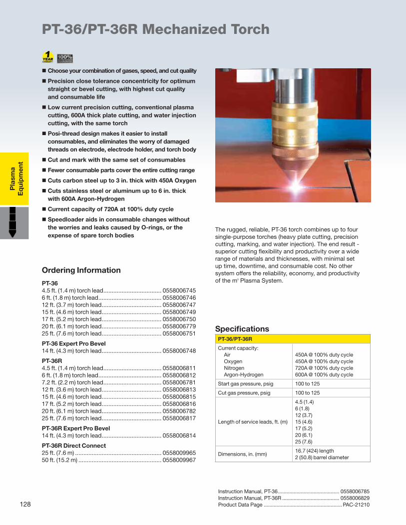
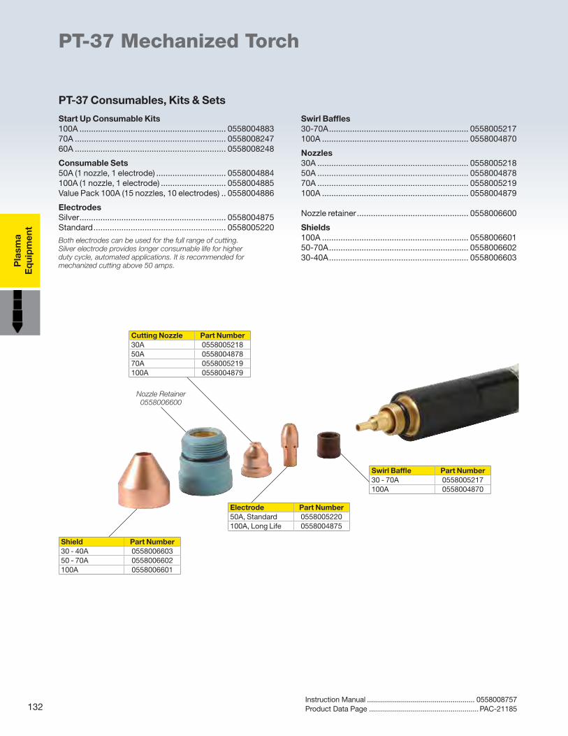
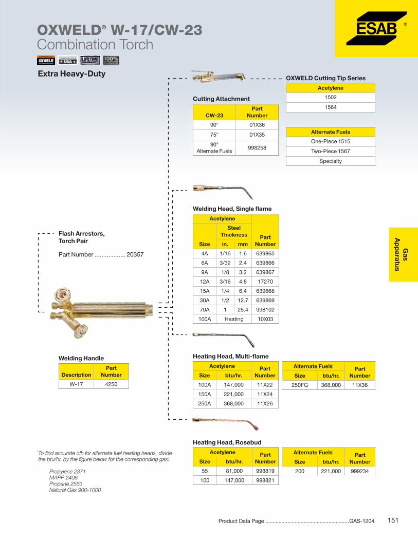
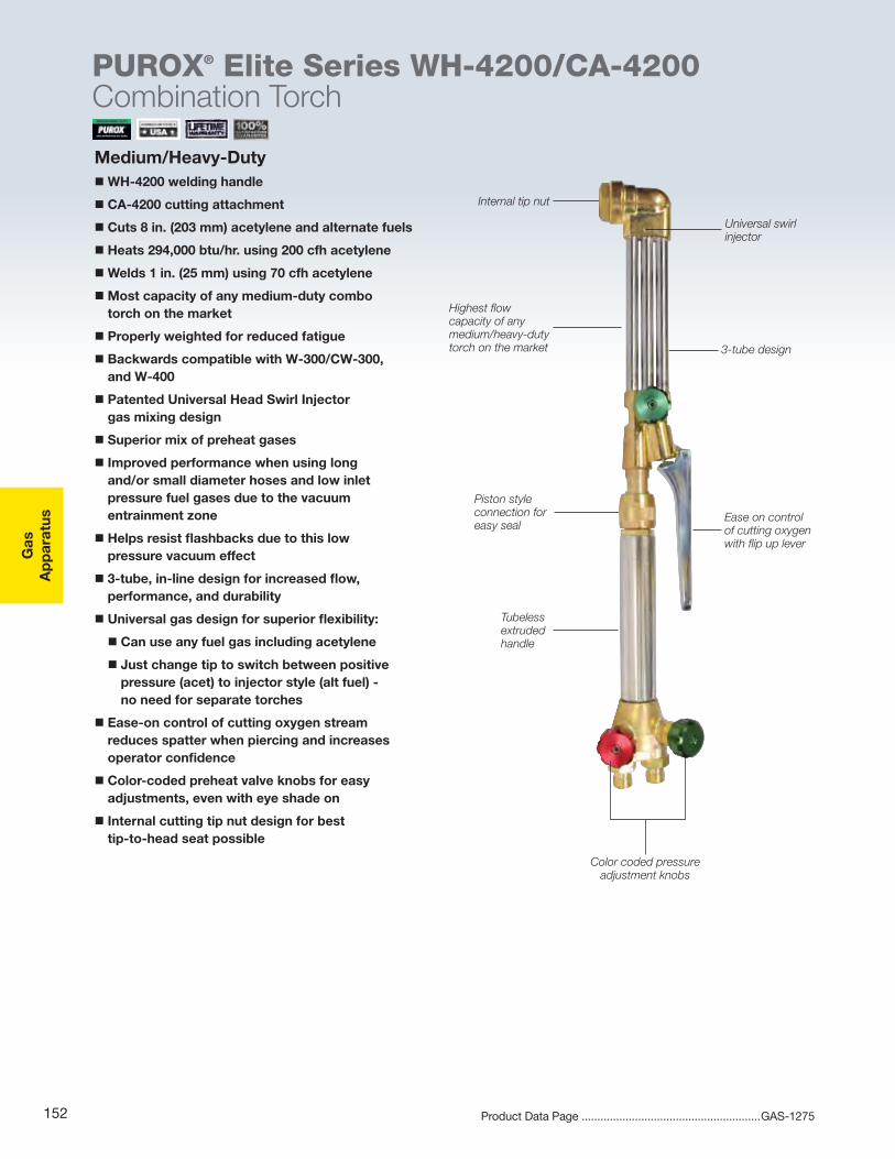
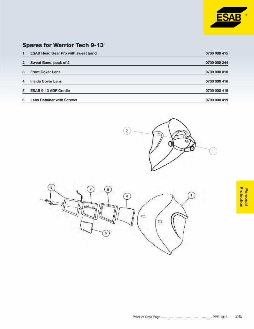
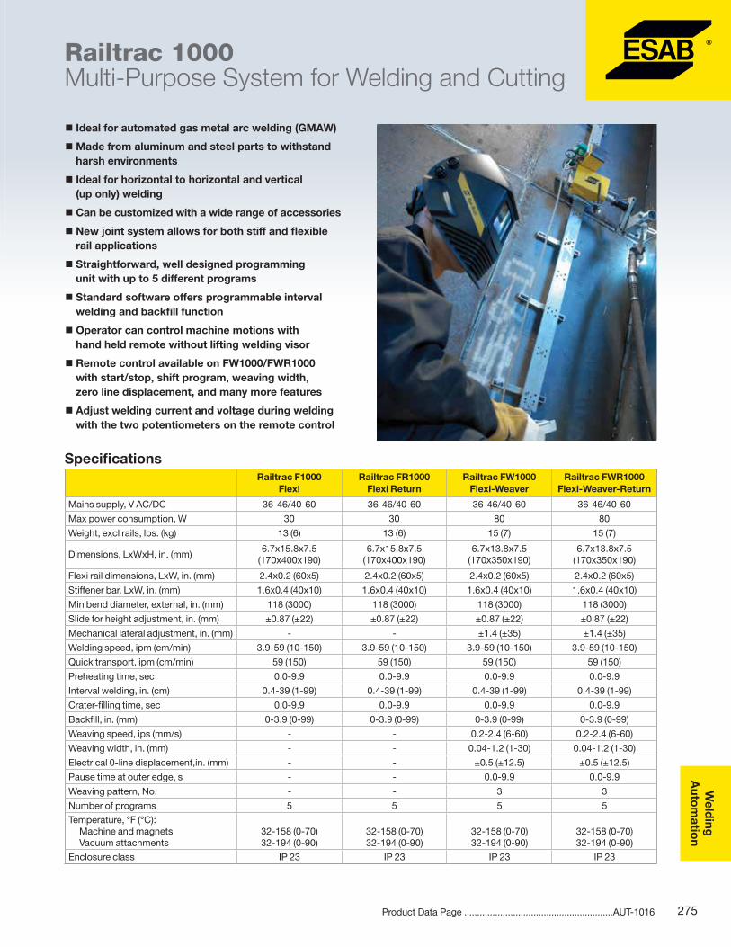
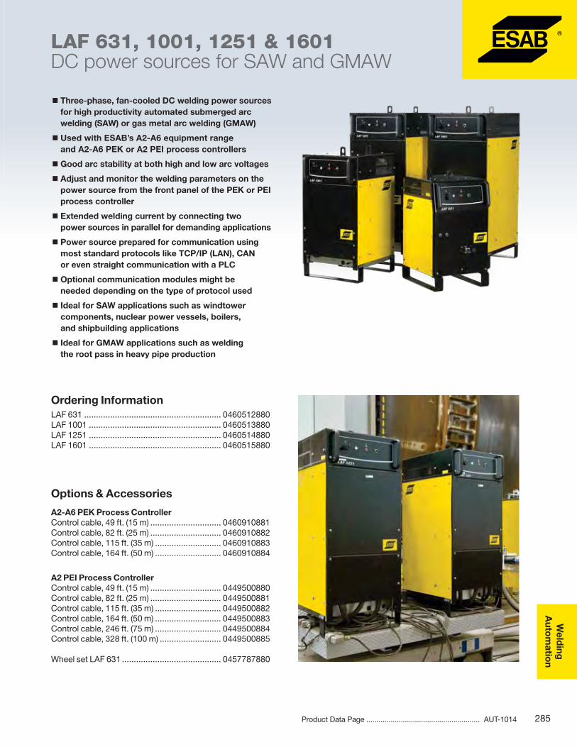
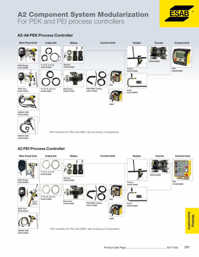
Welding & Cutting solutions from ESAB A full line of arc and plasma equipment, gas apparatus, personal protection equipment, mechanized cutting, and welding automation. 2014 Arc Equipment Gas Apparatus Welding Automation Mechanized Cutting Plasma Equipment Personal Protection
Transcript
Welding & Cutting solutions from ESAB
A full line of arc and plasma equipment, gas apparatus, personal protection equipment, mechanized cutting, and welding automation.
Value & Performance Equal ConfidenceESAB delivers superior-value performance that allows today’s industrial fabricator to attack any challenge with confidence.
Innovation Grounded in ExperienceOur innovative, world-renowned equipment and solutions are developed with input from our customers and built with the expertise and heritage of a global manufacuring leader.
A World of Products & SolutionsESAB’s reach extends to almost every nation in the world, with more than 8,600 employees, an established corporate presence in 47 countries, and 23 manufacturing facilities across 6 continents.
Certified, GloballyESAB is the first company in the world to achieve all-inclusive, external certification for the three key management standards - ISO 9001, ISO 14001, and OHSAS 18001. The Environmental, Health, and Safety Management System and certification covers all activities, people, and units in ESAB globally.
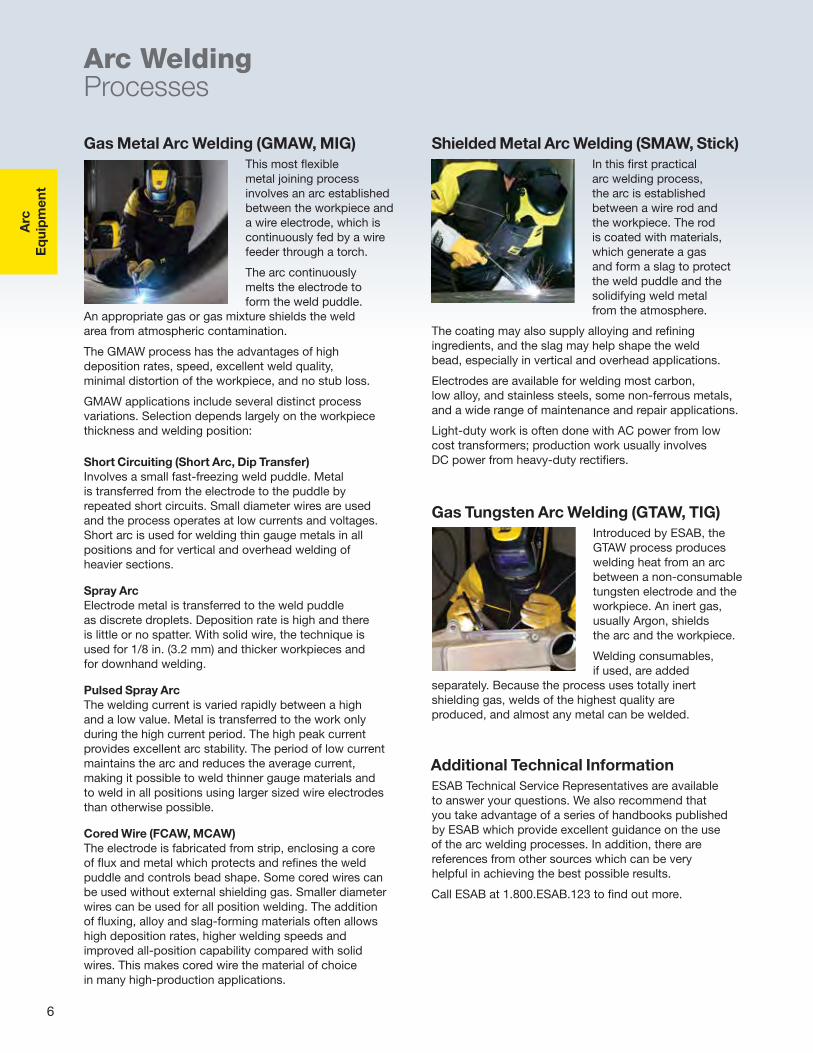
Gas Metal Arc Welding (GMAW, MIG) This most flexible metal joining process involves an arc established between the workpiece and a wire electrode, which is continuously fed by a wire feeder through a torch.
The arc continuously melts the electrode to form the weld puddle.
An appropriate gas or gas mixture shields the weld area from atmospheric contamination.
The GMAW process has the advantages of high deposition rates, speed, excellent weld quality, minimal distortion of the workpiece, and no stub loss.
GMAW applications include several distinct process variations. Selection depends largely on the workpiece thickness and welding position:
Shielded Metal Arc Welding (SMAW, Stick)In this first practical arc welding process, the arc is established between a wire rod and the workpiece. The rod is coated with materials, which generate a gas and form a slag to protect the weld puddle and the solidifying weld metal from the atmosphere.
The coating may also supply alloying and refining ingredients, and the slag may help shape the weld bead, especially in vertical and overhead applications.
Electrodes are available for welding most carbon, low alloy, and stainless steels, some non-ferrous metals, and a wide range of maintenance and repair applications.
Light-duty work is often done with AC power from low cost transformers; production work usually involves DC power from heavy-duty rectifiers.
Additional Technical Information ESAB Technical Service Representatives are available to answer your questions. We also recommend that you take advantage of a series of handbooks published by ESAB which provide excellent guidance on the use of the arc welding processes. In addition, there are references from other sources which can be very helpful in achieving the best possible results.
Call ESAB at 1.800.ESAB.123 to find out more.
Arc WeldingProcesses
Gas Tungsten Arc Welding (GTAW, TIG)Introduced by ESAB, the GTAW process produces welding heat from an arc between a non-consumable tungsten electrode and the workpiece. An inert gas, usually Argon, shields the arc and the workpiece.
Welding consumables, if used, are added
separately. Because the process uses totally inert shielding gas, welds of the highest quality are produced, and almost any metal can be welded.
Short Circuiting (Short Arc, Dip Transfer) Involves a small fast-freezing weld puddle. Metal is transferred from the electrode to the puddle by repeated short circuits. Small diameter wires are used and the process operates at low currents and voltages. Short arc is used for welding thin gauge metals in all positions and for vertical and overhead welding of heavier sections.
Spray ArcElectrode metal is transferred to the weld puddle as discrete droplets. Deposition rate is high and there is little or no spatter. With solid wire, the technique is used for 1/8 in. (3.2 mm) and thicker workpieces and for downhand welding.
Pulsed Spray ArcThe welding current is varied rapidly between a high and a low value. Metal is transferred to the work only during the high current period. The high peak current provides excellent arc stability. The period of low current maintains the arc and reduces the average current, making it possible to weld thinner gauge materials and to weld in all positions using larger sized wire electrodes than otherwise possible.
Cored Wire (FCAW, MCAW)The electrode is fabricated from strip, enclosing a core of flux and metal which protects and refines the weld puddle and controls bead shape. Some cored wires can be used without external shielding gas. Smaller diameter wires can be used for all position welding. The addition of fluxing, alloy and slag-forming materials often allows high deposition rates, higher welding speeds and improved all-position capability compared with solid wires. This makes cored wire the material of choice in many high-production applications.
Arc
Eq
uipm
ent
7
Arc WeldingProcesses
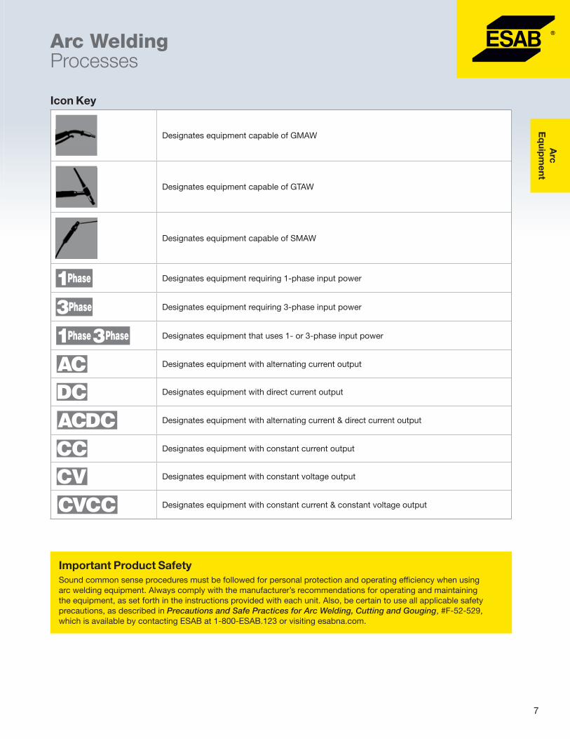
Important Product SafetySound common sense procedures must be followed for personal protection and operating efficiency when using arc welding equipment. Always comply with the manufacturer’s recommendations for operating and maintaining the equipment, as set forth in the instructions provided with each unit. Also, be certain to use all applicable safety precautions, as described in Precautions and Safe Practices for Arc Welding, Cutting and Gouging, #F-52-529, which is available by contacting ESAB at 1-800-ESAB.123 or visiting esabna.com.
Icon Key
Designates equipment capable of GMAW
Designates equipment capable of GTAW
Designates equipment capable of SMAW
Designates equipment requiring 1-phase input power
Designates equipment requiring 3-phase input power
Designates equipment that uses 1- or 3-phase input power
Designates equipment with alternating current output
Designates equipment with direct current output
Designates equipment with alternating current & direct current output
Designates equipment with constant current output
Designates equipment with constant voltage output
Designates equipment with constant current & constant voltage output
Arc
E
qui
pm
ent
8
Arc WeldingEquipment Selection Guide
GMAW GTAW SMAW
Rem
ote
Ctr
l, Vo
ltag
e
Rem
ote
Ctr
l, C
urre
nt
Sub
mer
ged
Arc
Arc
Go
ugin
g
Sho
rt A
rc
QS
et
Sp
ray
Arc
Flux
Co
red
Pul
se A
rc
Sup
erP
ulse
Ind
ucta
nce
Slo
pe
DC
AC
Live
TIG
Touc
h T
IG
Pul
sed
TIG
Hig
h Fr
eque
ncy
DC
AC
Arc
Fo
rce
Compact Packages (built-in wire feeder)
Caddy Mig C200i l l l l l
Migmaster 215 Pro l l l l
Migmaster 280 Pro l l l l
Power Sources
Warrior 500i l l l l l l l l l Opt l
Origo Mig 320 l l l l
Origo Mig 410 l l l l
Origo Mig 652c l l l l l Opt l l l l l
Origo Mig 4002c l m l l m t l Opt Opt m l l Opt
Origo Mig 5002cw l m l l m t l Opt Opt m l l Opt
Origo Mig 6502c l m l l m t l Opt Opt m l l Opt Opt
Aristo Mig U5000i l m l l m t l m m m l m m l l Opt
Aristo Mig U5000iw l m l l m t l m m m l m m l l Opt
Heliarc 281i AC/DC l l l l l l l l l l l
Heliarc 283i AC/DC l l l l l l l l l l l
Heliarc 353i AC/DC l l l l l l l l l l l
MiniArc 161LTS l l l
Caddy Arc 201i A33 l l l Auto l
Caddy Tig 2200i TA34 l l l(DC) l l l l
Caddy Tig 2200i AC/DC l l l l l(DC) l l l l l
Origo Arc 410c l l l l l l
Origo Arc 650c l l l l l l
Wire Feeders
Warrior Feed 304 l l l l l l l l l Opt l
MobileFeed 300AVS q l l q
Origo Feed 304 M12 l l l
Origo Feed 304 M13u l l l
Origo Feed 3004 MA23 m m m m m m l Opt
Origo Feed 3004 MA24 m m m m m m m l Opt
AristoFeed 3004 U6 m m m m m m m m m m m m m l Opt m
AristoFeed 3004 U82 m m m m m m m m m m m m m l Opt m
l Standard feature best performance. q Limited applications. t Use add-on pendant. mWhen used on corresponding Aristo or Mig 4002c/5002c/6502c power sources and feeder combination.
10Instruction Manual ...................................................... 0440001031Product Data Page .......................................................ARC-23287
Caddy® Mig C200i
� Easy-to-use, intelligent, and powerful inverter power source for GMAW applications with mild steels, aluminum, and stainless steel as well as GMAW brazing
� Lightweight and portable, the Caddy Mig is an excellent choice for repair, maintenance, and assembly work, both in the workshop and while on the go
�Weighing a little over 26 lbs. (12 kg), the Caddy Mig is the lightest welding unit in its output class
� Durable, impact-resistant housing made from advanced materials, including built-in cable, for easy transportation
� PFC (power factor correction) feature provides 30% more welding power from the same sized fuse
� QSet™ feature automatically sets the welding parameters and automatically adjusts during the process to maintain the optimum wire/gas combination and prevent waste of resources
� If you prefer, you can make adjustments with the wire feed speed and voltage
� A single-phase input connection makes it easy to find an electrical source and the machine performs equally as well when powered by a portable generator
� Built-in wire feeder fits a wire spool with an inner diameter of 2 in. (50 mm), external diameter of 8 in. (203 mm), and width of 2-1/8 in. (55 mm)
� Optimized to weld with .023 in. (0.6 mm), .030 in. (0.8 mm), and .035 in. (0.9 mm) solid or cored wires
�We recommend the following ESAB wires when welding with the Caddy Mig C200i:
� Spoolarc 86, .023, .030 and .035 in. for welding of mild steels
� Coreshield 15, .030 in. for gasless welding of mild steels
� ERCuSi-A .030 and .035 in. for GMAW brazing
� ESAB ER308LSi MIG .023, .030 and .035 in. for 18Cr 8Ni stainless steel welding
Includes: power source with built-in wire feeder, 10 ft. (3 m) MXL 180 torch, R-33-FM-580 regulator/flowmeter, 10 ft. (3 m) mains cable with 6-50P plug, 14.5 ft. (4.5 m) gas hose with ‘B’ male connector, 10 ft. (3 m) return cable with clamp, simple shoulder strap, fitted wear parts in torch/feeder (for .030 in. wire), 11 lbs. (5 kg) of 70S-6 mild steel .030 in. (0.8 mm) wire, and instruction manual.
Canada packages also include a 6-30/50P male plug.
Options & AccessoriesTrolley (includes gas shelf) .............................. 0459366887Feedrolls, V-groove .023-.030 in. (0.6-0.8 mm)
U-groove .040 in. (1.0 mm) .......................... 0349312836
Arc
Eq
uipm
ent
11Instruction Manual ...................................................... 0440001031Product Data Page .......................................................ARC-23287
Caddy® Mig C200i
Specifications Caddy Mig C200i
Input voltage 230V, 1ph, 50/60Hz
Fuse (slow) 16A
Maximum welding output 200A
Permitted load at:25% duty cycle 100% duty cycle
180A/23V100A/19V
Setting range 30-200A
Open circuit voltage 60V
Wire feed speed, ipm (m/min) 78-472 (2-12)
Max. size of the wire reel, in., lbs. (mm, kg) 8, 10 (200, 5)
Open circuit power 15W
Power factor at maximum current 0.99
Efficiency at maximum current 82%
Dimensions, LxWxH, in. (mm) 17.68x7.8x13.66 (449x198x347)
Weight with torch and cables, lbs. (kg) 26 (12)
Enclosure class IP 23
Operating temperature, °F (°C) 14 to 104 (-10 to 40)
Wear PartsItem Description Part Number
A Gas nozzle 07002000541
B Contact tip for .030 in. (0.8 mm) wire 07002000641
B Contact tip for .035 in. (0.9 mm) wire 0700200066
C Nozzle spring 07002000781
D Tip adaptor 07002000721
E Steel liner .023 - .030 in. (0.6 - 0.8 mm) wire 07002000861
E Steel liner .035 - .045 in. (0.9 - 1.2 mm) wire 0700200088
F Feed roller with groove 03493118901
G Pressure roller 03493120621
H Inlet nozzle 04550490021
1As delivered. See MXL 200 torch for additional nozzles, tips, and liners.
F
E
G
H
A B C D
Arc
E
qui
pm
ent
12Instruction Manual ...................................................... 0349301164Product Data Page .......................................................ARC-23281
Migmaster® 215 Pro & 280 Pro
� Sturdy, robust step-controlled welding power sources
� Intended for medium (215 Pro) to heavy-duty (280 Pro) GMAW applications with solid wires of steel, stainless steel, and aluminum, as well as cored wires with or without shielding gas
� ESAB’s proven technology and software provide reliability and outstanding welding performance
�Made with a strong galvanized metal casing to withstand harsh environments
� Large wheels and built-in wire feeder make these machines practical, mobile solutions
� The units are fan-cooled and equipped with thermal overload protection
� A wide current and voltage range, plus two inductance outlets (280 Pro) make it easy to optimize settings for a variety of consumables and shielding gases
� Equipped with V/A digital meter with hold feature
� Equipped with the potentiometers to set the wire feed speed, spot welding time, and burnback time adjustment
� Equipped with additional functions such as creep start and inching
Ordering Information
Migmaster 215 Pro Ready to Weld Packages208/230V, 1ph, 15 ft. (4.5 m), GM-250 ............. 0558101322208/230V, 1ph, 13 ft. (4 m), MXL 270* ............. 0561000000
Migmaster 215 Pro Spool Gun Packages230V, 1ph, 15 ft. (4.5 m), GM-250 MT-250SG* . 0561000001230V, 1ph, 13 ft. (4 m), MXL 270 MT-250SG* ... 0561000002
Includes: power source with built-in wire feeder with .030-.045 in. (0.8-1.2 mm) drive roll, guide tube, 10 ft. (3 m) primary input cable with plug, gas hose, undercarriage, cylinder rack, GunMaster 250 or MXL 270 torch, 10 ft. (3 m) work cable with clamp, R-33 regulator/flowmeter, 40-lb (18-kg) spool of .035 in. (0.9 mm) solid wire.
Migmaster 280 Pro Ready to Weld Packages208/230V, 1ph, 15 ft. (4.5 m), GM-250 ............. 0558101324208/230V, 1ph, 13 ft. (4 m), MXL 340* ............. 0561000010208-575V, 1ph, 15 ft. (4.5 m), GM-250 ............ 0558101365208-575V, 1ph, 13 ft. (4 m), MXL 340* ............. 0561000015
Migmaster 280 Pro Spool Gun Packages230V, 1ph, 15 ft. (4.5 m), GM-250/MT-250SG* 0561000011230V, 1ph, 13 ft. (4 m), MXL 340/MT-250SG* .. 0561000012208-575V, 1ph, 15 ft. (4.5 m), GM-250/MT-250SG* 0561000016208-575V, 1ph, 13 ft. (4 m), MXL 340/MT-250SG* 0561000017
Includes: power source with built-in wire feeder with .030-.045 in. (0.8-1.2 mm) drive roll, guide tube, 10 ft. (3 m) primary input cable, gas hose, undercarriage, cylinder rack, GM-250 or MXL 340 torch, 10 ft. (3 m) work cable with clamp, and R-33 regulator/flowmeter. 230V packages include primary plug.
*Available in Canada only.
Arc
Eq
uipm
ent
13Instruction Manual ...................................................... 0349301164Product Data Page .......................................................ARC-23281
Migmaster® 215 Pro & 280 Pro
Options & Accessories
Air Filters Migmaster 215 Pro ......................................... 0349302599Migmaster 280 Pro ......................................... 0349312810
Cable & Torch HoldersMigmaster 215 Pro ......................................... 0349303362Migmaster 280 Pro ......................................... 0349312800
� Step-switched power sources for medium (320) to heavy-duty (410) GMAW applications
�Made with a strong galvanized metal casing to withstand harsh environments
� Large wheels, sturdy lifting eyelets, and an undercarriage designed for forklift transport make the Origo Mig easy to move
� The wide current and voltage range make it easy to optimize settings for a wide variety of consumables and shielding gases
� Optimized to operate together with the Origo Feed 304 M12 wire feeder available with 1.18 in. (30 mm) diameter feed rolls for wires up to 1/16 in. (1.6 mm) diameter
� Electronically controlled feeding gives an accurate and stable arc
� The wire feed unit sits on a swivel post mounted on the top of the power source, providing a 360° radius of operation
� The feeder mechanism is easy to access, and all wear parts can easily be exchanged
� A single pressure device makes it easy to adjust the appropriate feeding pressure
� All electronic components are protected in a separate compartment
Includes: power source, 16 ft. (5 m) work cable/ground clamp, factory installed wheel kit, 6 ft. (1.7 m) cable connection kit, Origo Feed 304 wire feeder with M12 panel, .035/.045 in. (0.9/1.2 mm) V-groove drive rolls/guide tube, swivel mounting post for wire feeder, gas cylinder rack, 15 ft. (4.5 m) GunMaster 400cc torch with .035/.045 in. (0.9/1.2 mm) accessories and R-33-FM-580 gas regulator with adjustable flowmeter.
Includes: power source, wire feeder, and 15 ft. (4.5 m) 400A torch.
Options & AccessoriesOrigo Mig 320 air filter ..................................... 0349302599Origo Mig 410 air filter ..................................... 0349302423Cable holder kit ............................................... 0349303362Origo MIG 320 stabilizer kit for MiniBoom ....... 0349303475Origo MIG 410 counterbalance kit for MiniBoom1 .. 0349305812Reinforcer kit for mounting MiniBoom2 ............ 03493097481Includes counterbalance kit #0349309748 and stabilizer #0349303474. 2Stabilizer kit required.
Feeder AccessoriesWheel kit ........................................................ 0458707880Strain relief for welding torch .......................... 0457341881Feeder strain relief for connection cables ....... 0459234880Lifting eye ....................................................... 0458706880Quick connector Marathon Pac ...................... F102440880Adapter for 11-lb (5-kg) spool ........................ 0455410001Steel spool cover, 12 in. (305 mm) .................. 0459431880
Counterbalance MiniBoomFor 12 in. (305 mm) spools .............................. 0458705880For 18 in. (457 mm) spools .............................. 0458705882
Extension bracket for 60-lb coil (18 in. spools) 0459233880Coil adaptor (requires 0459233880) ......................... 34323Inching and gas purge kit ............................... 0459465880
Setting range (DC) 40A/16V–320A/30V 50A/16.5V–400A/34V
Open circuit voltage 16–40V 17–45V
Open circuit power 200W 360W
Open circuit power with cooling unit - 600W
Power factor at maximum current 0.94 0.98
Efficiency at maximum current 75% 71%
Control voltage 42V, 50/60Hz -
Voltage steps 40 40
Inductance outlets 2 2
Dimensions, LxW xH, in. (mm) 33x16x32 (840x425x830) 32x21x36 (812x552x925)
Weight, lbs. (kg) 244 (111) 317 (144)
Weight with cooling unit, lbs. (kg) - 348 (158)
Operating temperature, °F (°C) 14 to 104 (-10 to 40) 14 to 104 (-10 to 40)
Enclosure class IP 23 IP 23
1230/460/575V available in Canada.
Origo Feed 304 M12 Wire Feeder Data
Power Supply
Wire Spool Capacity, lbs. (kg)
Max. Spool Diameter, in. (mm)
Wire Feed Speed, ipm (m/min)
Dimensions (LxWxH), in. (mm)
Weight Enclosed, lbs. (kg) Wire Dimensions, in. (mm)
42 VAC, 50/60 Hz
44 (19) or 60 (27)1
12 (300)2 31-1000 (0.8-25) 27 x11x16(690 x 275 x 420)
33 (15) Steel Stainless steel Aluminum Cored wire
.023–1/16 (0.6–1.6)
.023–1/16 (0.6–1.6)
.040–1/16 (1.0–1.6)
.030–1/16 (0.8–1.6)
1Requires optional accessories. 2Enclosed.
Options & Accessories continued
Connection Cable Sets
Air-Cooled Torch, 23 Pole5.5 ft. (1.7 m) ................................................... 034931247016.4 ft. (5 m) ................................................... 034931247132.8 ft. (10 m) ................................................. 034931247249 ft. (15 m) ..................................................... 034931247382 ft. (25 m) .................................................... 0349312474115 ft. (35 m) ................................................... 0349312475
Includes: control cable, electrode cable, and gas hose.
GunMaster 400cc Torches25 ft. (7.6 m) basic ........................................... 055800167412 ft. (3.6 m) x .035-045 in. (0.9-1.2 mm) ......... 055800166715 ft. (4.5 m) x .035-045 in. (0.9-1.2 mm) ......... 0558001669 15 ft. (4.5 m) x .052-1/16 in. (1.3-1.6 mm) ........ 0558001670
See ARC-23095 for additional information.
Arc
E
qui
pm
ent
16 Product Data Page .......................................................ARC-23178
MXL™ GMAW Guns
� Designed to provide the utmost in convenience and versatility
GunMaster 250 10 ft. (3 m) x .023 in. (0.6 mm) .......................... 055800163010 ft. (3 m) x .035-.045 in. (0.9-1.1 mm) ........... 055800163112 ft. (3.6 m) x .035-.045 in. (0.9-1.1 mm) ........ 055800163515 ft. (4.5 m) x .035-.045 in. (0.9-1.1 mm) ........ 0558001639
GunMaster 400 10 ft. (3 m) x .035-.045 in. (0.9-1.1 mm) ........... 055800165312 ft. (3.6 m) x .035-.045 in. (0.9-1.1 mm) ........ 055800165612 ft. (3.6 m) x .052-1/16 in. (1.3-1.6 mm) ........ 055800165715 ft. (4.5 m) x .035-.045 in. (0.9-1.1 mm) ........ 055800165915 ft. (4.5 m) x .052-1/16 in. (1.3-1.6 mm) ........ 0558001660
Complete Assemblies CC Style
GunMaster 250cc 10 ft. (3 m) x .035-.045 in. (0.9-1.1 mm) ........... 055800164412 ft. (3.6 m) x .035-.045 in. (0.9-1.1 mm) ........ 055800164515 ft. (4.5 m) x .035-.045 in. (0.9-1.1 mm) ........ 0558001649
GunMaster 400cc12 ft. (3.6 m) x .035-.045 in. (0.9-1.1 mm) ........ 055800166715 ft. (4.5 m) x .035-.045 in. (0.9-1.1 mm) ........ 055800166915 ft. (4.5 m) x .052-1/16 in. (1.3-1.6 mm) ........ 0558001670
Basic NAS StyleGun Master 400 NAS, 25 ft. (7.6 m) ................. 0558001664
Basic CC StyleGun Master 400cc, 25 ft. (7.6 m) ..................... 0558001674
GunMaster 250 & 400
Options & Accessories continued
Liner Selection
Steel/Flux Core.023 in. (0.6 mm) x 10,12,15 ft.(3, 3.6, 4.5 m) ... 0558001675.030 in. (0.8 mm) x 10,12,15 ft. (3, 3.6, 4.5 m) ............ 37031.035/.045 in. (0.9/1.1 mm) x 10,12,15 ft. (3, 3.6, 4.5 m) .. 37032.052-1/16 in. (1.3-1.6 mm) x 10,12,15 ft. (3, 3.6, 4.5 m) .. 370335/64 in. (2.0 mm) x 10,12,15 ft. (3, 3.6, 4.5 m) .. 05580016763/32 in. (2.5 mm) x 10,12,15 ft. (3, 3.6, 4.5 m) ............ 370347/64-1/8 in. (2.8-3.2 mm) x 10,12,15 ft. (3, 3.6, 4.5 m) .. 952948.035 - .045 in. (0.9-1.1 mm) x 25 ft. (7.6 m) ...... 0558002137.052 - 1/16 in. (1.3-1.6 mm) x 25 ft. (7.6 m) ...... 05580021385/64 in. (2.0 mm) x 25 ft. (7.6 m) ....................... 05580021393/32 in. (2.5 mm) x 25 ft. (7.6 m) ....................... 0558002140
Aluminum.035-3/64 in. (0.9-1.2 mm) x 15 ft. (4.5 m) poly .......... 370393/64-1/16 in. (1.2-1.6 mm) x 15 ft. (4.5 m) poly .......... 37040
Requires jumper sleeve #0558006682 when H.D. parts used. Note: All 15 ft. (4.5 m) liners can be trimmed to fit 10 ft. (3 m) or 12 ft. (3.6 m). For use with Origo Feed MA23/MA24, and Aristo Feed U6/U82 Plus.
Aluminum Optimization Kits For use with Origo Feed/Aristo Feed wire feeders.035 in. (0.9 mm) and 3/64 in. (1.2 mm) Al ........ 05580078413/64 in. (1.2 mm) and 1/16 in. (1.6 mm) Al ........ 0558007842
Includes: 15 ft. (4.5 m) liners (CER/TFE), drive roll guides (4),tips (2 ea. size for kit), nozzle H.D. 5/8 in. (19 mm) and jumper sleeve.
� "Slide-on" standard and heavy-duty copper wall nozzles deliver performance and dependability
� Lightweight handle is impact resistant for long life
� Cable resists cuts, spatter, oil, and abrasion
EURONAS
Options & AccessoriesESAB power pin .............................................. 0558002313Lincoln power pin ........................................... 055800186245°, 250A gooseneck1 ..................................... 0558001616Gas meter2 ................................................................ 19043 GMAW gun holder .......................................... 0760022300 1For GunMaster 250. 2Measures gas flow at the gun.
Trigger Leads, ESAB Style for NAS Style GunsGunMaster 250, 6 in. (0.15 m) ......................... 0558001815GunMaster 250, 24 in. (0.6 m) ......................... 0558002583GunMaster 400 ..................................................... 2075216
Control Plugs (Options)Lincoln (LN 7, 8, 9, NAS) ................................. 0558001864
Ratings are based on tests that comply with NEMA ARC Welding Section Standard 11-6-1975 for duty cycle. “The time period of one complete cycle shall be 10 minutes” (60% = 6 minutes). National Electrical Manufacturers Association 2101 L Street N.W., Washington, D.C., 20037.
Contact Tips Standard-Duty Tips Heavy-Duty Tips
Wire Size, in. (mm) Part Number Wire Size, in. (mm) Part Number
� ST-21M has an in-line body style designed for mechanized applications
ST-16
ST-21M
Ordering InformationST-16, 10 ft. (3 m) .................................................... 997498ST-21, 12 ft. (3.6 m) ................................................. 995950ST-21M, 2 ft. (0.6 m) ................................................ 690509
Does not include liner/conduits, contact tips/tubes or nozzles.
Options & AccessoriesWarrior Feed 304 for ST-21 & ST-16 ................ 0588002048Spatter liner ............................................................ 633603Centering bushing .................................................... 17782EH-10A mech. Gun mounting bracket (ST-21M) .... 633885EH-10A connection block assembly (ST-21M) .......... 58V74Outlet guide, .045-1/16 in. (1.2-1.6 mm) ......... 0588000995Power cable adaptor ................................................ 45V11Gas meter1 ................................................................ 190431Measures gas flow at the gun.
ST-21M requires bracket #633885 and adaptor #61N59 for use with the above conduits when mounting away from feeder. Refer to torch manuals for specific accessories required to install on wire feeder (available online at esabna.com).
Arc
E
qui
pm
ent
22
Instruction Manual, ST-23A ..............................................F-14-353Instruction Manual, MT-250SG .........................................F-15-380Product Data Page .......................................................ARC-23066
ST-23A Feed Rolls.030-.035 in. (0.8-0.9 mm) ....................................... 636343.045-.062 in. (1.2-1.6 mm)5 ...................................... 996112
Torch LinersTorch liner, .045-.062 in. (1.2-1.6 mm)5 ...................... 19167Torch liner, .030-.035 in. (0.8-0.9 mm) ....................... 191661For gun service line protection. 2Extends spool gun control cable by 30 ft. (9 m). 3Includes coupling #11N19 for extending 30 ft. (9 m). 4For Migmaster 215 & 280 PRO. 5As delivered.
Gas meter (measures gas flow at the gun) ................ 19043Feedroll .030-3/64 in. (0.8-1.2 mm) soft wire2 ............ 36866Feedroll knurled .030-.045 in. (0.8-1.2 mm) hard wire 36867Inlet guide liner .030-3/64 in. (0.8-1.2 mm) gray ........ 36869Barrel liner .030-3/64 in. (0.8-1.2 mm) white ............. 368711For gun service line protection. 2As delivered.
GMAW Spool Gun Packages
Contact Tips
Wire Size, in. (mm)Inside Diameter,
in. (mm) Short
Contact Tips
Standard-Duty Medium1
Standard-Duty Long
Heavy-Duty Medium2
.023 (0.6) 0.031 (0.8) - 20543 999742 -
.030 (0.8) 0.037 (0.9) - 20544 996994 0558002367
.030 (0.8) (Notched) 0.043 (1.1) - 36884 - -
.035 (0.9) 0.043 (1.1) - 996995 996996 0558002368
.035 (0.9) (Notched) 0.048 (1.2) - 36885 - -
.040 (1.0) 0.048 (1.2) - 37287 - 0558002369
.045 (1.2) 0.054 (1.4) 999578 37290 996998 37286
3/64 (1.2) (Notched) 0.060 (1.5) - 368863 - -
3/64 (1.2) 0.058 (1.5) - 9969994 - 17765
1Requires tip adaptor #17983. 2Requires tip adaptor #17984. 3Included with MT-250SG. 4Included with ST-23A.
Nozzles Size Inside Diameter, in. (mm) Standard-Duty Heavy-Duty
6 3/8 (10) 998895 -
8 1/2 (13) 998893 -
8 HD 1/2 (13) - 999471
10 5/8 (16) 998894 -
10 HD 5/8 (16) - 9994721
12 HD 3/4 (20) - 999473
12 Spot 3/4 (20) - 999625
1Included with ST-23A and MT-250SG.
Arc
E
qui
pm
ent
24Instruction Manual ...................................................... 0460443101Product Data Page .......................................................ARC-23252
Caddy™ Tig 2200i DC
� Fifth generation Caddy machines feature advanced inverter technology built-in delivering unparalleled performance in a rugged, portable package
� Designed for quality GTAW applications with a variety of metals
� Extremely easy to use - all welding parameters displayed in an easy-to-understand format
� The TA34, 2-program function panel allows pre-programming and program changes during welding
� The TA34 panel also includes dual memory settings, switchable from the panel or torch trigger, and the capacity to set slope up/down and post-gas
� Pulsed TIG feature for greater control of heat input and weld pool
�Micro Pulse minimizes the heat affected zone, particularly when working with thin metals
� ArcPlus II improves welding characteristics and simplifies work for better weld quality with less clean up
� Hot Start and Arc Force settings create true SMAW characteristics
� Equipped with large OKC50 cable connectors for greater durability
� Compact design with impact resistant polymer and aluminum casing makes this unit lightweight and easy to carry
� Large heat sinks and innovative design make these Caddy machines run cooler for longer machine life even when used in harsh environments
� Designed to keep sensitive interior parts clean and dust free
� Built in accordance with IP 23 for outdoor use, even in wet weather conditions making Caddy Tig ideal for on-site work
� Equipped with a PFC (Power Factor Correction) circuit to allow the machine to perform a full range of functions on a 16A fuse, protects against fluctuating input voltage, and makes it safer to use with a generator
� Caddy Tig supplies direct current and allows you to weld most metals including alloy and non alloy steel, stainless steel and cast iron
� Caddy Tig welds electrodes up to 5/32 in. (4 mm) diameter
Includes: power supply, TXH-201 torch 13 ft. (4 m) w/ remote on/off contactor, "crocodile" type electrode holder with10 ft. (3 m) cable, GTAW accessory kit, R-33 regulator/flowmeter, 5 ft. (1.5 m) gas hose, 10 ft. (3 m) work cable and ground clamp, and 10 ft. (3 m) primary cable with plug.
2-Wheel TrolleySmall gas bottle ............................................. 0459366885Gas bottle on side ........................................... 0460330880
Remote ControlsAT 1 CAN ........................................................ 0459491883AT1 CoarseFine CAN ...................................... 0459491884MTA1 CAN ..................................................... 0459491880Foot pedal T1 CAN, with 16.4 ft. (5 m) cable ... 0460315880
Connection Cables for Remote Controls16.4 ft. (5 m) CAN ............................................ 045955488033 ft. (10 m) CAN ............................................. 045955488149 ft. (15 m) CAN ............................................. 045955488282 ft. (25 m) CAN ............................................. 0459554883
GTAW Torches TXH-201, 13 ft. (4 m), OKC50 .......................... 0700300552TXH-201F, 13 ft. (4 m), OKC50 ........................ 0700300545TXH-201r, 13 ft. (4 m), OKC50 ......................... 0700300628TXH-201Fr, 13 ft. (4 m), OKC50 ....................... 0700300629
Electrode holder screw-type 150A, 10 ft. (3 m) 0700006898Electrode holder screw-type 200A, 10 ft. (3 m) 0700006900Return cable 150A, 10 ft. (3 m) ........................ 0700006899Return cable 200A, 10 ft. (3 m) ........................ 0700006901Remote adaptor kit1 ........................................ 0459491912GTAW torch holder .......................................... 0760022400GTAW accessory kit ................................................ 9991261Includes holder for remote models.
Arc
Eq
uipm
ent
25Instruction Manual ...................................................... 0460443101Product Data Page .......................................................ARC-23252
Permitted load at (SMAW):25% duty cycle,60% duty cycle100% duty cycle
170A/26.8V130A/25.2V110A/24.4V
Setting range A, DC:GTAWSMAW
3-2204-170
Open circuit voltage, V 72 V
Power factor at max. current, GTAW/SMAW 0.99
Efficiency at max. current:GTAWSMAW
5%81%
Dimensions, LxWxH, in. (mm) 16.46x7.40x8.19 (418x188x208)
Weight, lbs. (kg) 20.72 (9)
Enclosure class IP 23
Arc
E
qui
pm
ent
26Instruction Manual ...................................................... 0460225101Product Data Page .......................................................ARC-23253
Caddy™ Tig 2200i AC/DC
� Unparalleled performance in a mobile machine for a wide range of GTAW (TIG) and SMAW (Stick) applications
� Designed for quality GTAW applications with all types of metals
� Extremely easy to use - all welding parameters displayed in an easy-to-understand format
� Innovative QWave™ feature enables AC welding with exceptional arc stability and low noise
� AC frequency and balance control optimizes weld pool
� Electrode preheating facilitates excellent starts and extends electrode life
� The TA34, 2-program function panel allows pre-programming and program changes during welding
� AC Balance to control arc cleaning and penetration, AC Frequency to control arc width, and a special setting to control electrode preheating for better starts with a variety of electrodes
� DC Pulsed TIG welding for easy control of heat input and weld pool
�Micro Pulse minimizes the heat affected zone, particularly when working with thin metals
� Hot Start, Arc Force and polarity switch (DC) creates true SMAW characteristics in AC and DC mode
� Equipped with large OKC50 cable connectors for greater durability
� Features compact design with impact resistant polymer and aluminum casing – makes the unit lightweight and easy to carry
� Small size does not compromise vital cooling of internal components
� Large heat sinks and innovative design make these Caddy machines run cooler - promotes longer machine life even when used in harsh environments
� Designed to keep sensitive interior parts clean and dust free
� Built in accordance with IP 23 for outdoor use, even in wet weather conditions - makes this machine ideal for on-site work
� Equipped with a PFC (Power Factor Correction) circuit - allows the machine to perform a full range of functions on a 16A fuse, protects against fluctuating input voltage, and makes it safer to use with a generator
Ordering InformationCaddy Tig 2200i AC/DC, standard .................. 0460150883
Includes: power supply, TXH-201 torch 13 ft. (4 m) w/remote on/off contactor, electrode holder with 10 ft. (3 m) cable, GTAW accessory kit, regulator/flowmeter, 7 ft. (2 m) gas hose, 15 ft. (4.5 m) work cable and ground clamp, and 10 ft. (3 m) primary cable with plug.
Caddy Tig 2200iw AC/DC with water cooler ... 0460150884
Includes: 10 ft. (3 m) of mains cable, no plug, 5 ft. (1.5 m) of gas hose with 2 hose clamps, 10 ft. (3 m) return cable with work clamp, SMAW kit, 2-wheel trolley, and CoolMini water cooler.
Caddy Tig 2200i AC/DC with finger control* ... 0561000125
Includes: power supply, RA T1 remote adaptor, TXH-201r torch 13 ft. (4 m) w/remote on/off contactor and variable current control, electrode holder w/10 ft. (3 m) cable, GTAW accessory kit, regulator/flowmeter, 7 ft. (2 m) gas hose, 15 ft. (4.5 m) work cable and ground clamp, and 10 ft. (3 m) primary cable with plug.
Caddy Tig 2200i AC/DC with foot control* ...... 0561000126
Includes: power supply, TXH-201 torch 13 ft. (4 m) w/remote off/on contactor, T1-CAN foot control with 16.4 ft. (5 m) cable, electrode holder with 10 ft. (3 m) cable, GTAW accessory kit, regulator/flowmeter, 7 ft. (2 m) gas hose, 15 ft. (4.5 m) work cable and ground clamp, and 10 ft. (3 m) primary cable with plug.
*Available in Canada only.
Arc
Eq
uipm
ent
27Instruction Manual ...................................................... 0460225101Product Data Page .......................................................ARC-23253
Dimensions, LxWxH, in. (mm) 16.5x7.4x13.6 (418x188x345)
Weight, lbs. (kg) 33 (15)
CoolMini Water Cooling Unit
Cooling capacity, W 700W/0.264 g.p.m. at 104°F (700W/1 l.p.m. at 40°C)
Coolant volume, gal. (L) 0.581 (2.2)
Maximum flow, gal/min (L/min) 0.528 (2.0)
Maximum pressure, 50/60Hz, psi (bar) 33.4 (2.3)
Weight, lbs. (kg) 10/15 (4.5/6.7)
Dimensions, LxWxH, in. (mm) 16.5x7.4x5.4 (418x188x137)
TA34 Control Panel
Slope up/down, sec 0-10
Gas pre-flow, sec1 0-5
Gas post-flow, sec 0-25
Pulse, background time, DC, sec 0.01-2.5
MicroPulse, sec1 0.001-0.250
Frequency AC, Hz 10-152
AC balance, % 50-98
1Hidden functions.
Options & AccessoriesCoolMini cooling unit ...................................... 0460144880
2-Wheel TrolleySmall gas bottle ............................................. 0459366885Gas bottle on side ........................................... 0460330880
Remote ControlsAT1-CAN ......................................................... 0459491883AT1 CoarseFine CAN ...................................... 0459491884MTA1 CAN ..................................................... 0459491880T1Foot CAN, 16.4 ft. (5 m) cable ..................... 0460315880
Connection Cables for Remote Controls16.4 ft. (5 m) .................................................... 045955488033 ft. (10 m) ..................................................... 045955488149 ft. (15 m) ..................................................... 045955488282 ft. (25 m) ..................................................... 0459554883
GTAW TorchesTXH-201, 13 ft. (4 m) OKC50 ........................... 0700300552TXH-201V, 13 ft. (4 m) OKC50 ......................... 0700300553TXH-201F, 13 ft. (4 m) OKC50 ......................... 0700300554TXH-251w, 13 ft. (4 m) OKC50 ........................ 0700300561TXH-251wF, 13 ft. (4 m) OKC50 ...................... 0700300562TXH-251w, 26 ft. (8 m) OKC50 ........................ 0700300563TXH-251wF, 26 ft. (8 m) OKC50 ...................... 0700300564
F = Flexible. V = Gas Valve.
Remote adaptor RA T1, 82 ft. (25 m) cable ...... 0459491912GTAW torch holder .......................................... 0760022400Electrode holder screw-type 150A, 10 ft. (3 m) 0700006898Electrode holder screw-type 200A, 10 ft. (3 m) 0700006900Return cable 150A, 10 ft. (3 m) ........................ 0700006899Return cable 200A, 10 ft. (3 m) ........................ 0700006901Shoulder strap, padded .................................. 0460265003
Arc
E
qui
pm
ent
28Instruction Manual ...................................................... 0558012079Product Data Page .......................................................ARC-23305
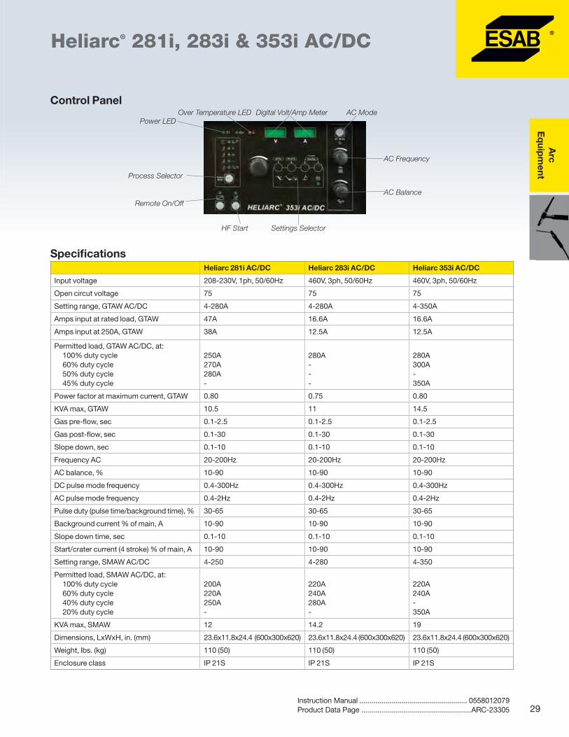
Heliarc® 281i, 283i & 353i AC/DC
� Designed for quality GTAW and SMAW applications in all types of material
� Cost effective inverter technology at an SCR price - increased energy efficiency and more power from a lighter, smaller, and more portable unit
� Easy-to-control arc heat input for high quality welds
� Intuitive interface for easy setup and adjustment
� Digital controls ensure high accuracy and repeatability
� AC or DC Pulsed TIG welding - easy control of heat input and weld pool
� AC Hot Start is available at currents below 130A to boost current at the initial start to improve weld puddle initiation and arc penetration
� Control the arc with remote or foot control - switch between two currents by pressing torch switch
� Live TIG is ideal in places where high-frequency (HF) is not allowed
� AC Pulsing up to 2Hz makes Heliarc ideal for welding thin aluminum material
� Easily store up to 60 parameter sets for quick changes while working
Options & AccessoriesWater cooler module ....................................... 0558101703Coolant, 1 gal. (3.8 L) ...................................... 0560950312Cart kit1 ........................................................... 0558101702Foot control FC-5C, 30 ft. (9 m) ....................... 0558004234Electrode holder, 175A, 15 ft. (4.5 m)............... 0558001791Electrode holder, 300A, 15 ft. (4.5 m)......................... 21226Quick connect "T", 1 male/2 female fittings .... 0365557001Quick lock connector male, 1/0 to 2/0 cable ... 0160360881Quick lock connector female, 1/0 to 2/0 cable .... 13735632Quick lock connector male, 1/0 to 4/0 cable ... 0160360882Quick lock connector female, 1/0 to 4/0 cable .... 13735631Work cable clamp and QD, 15 ft. (4.5 m) ................... 36253Work cable clamp and QD, 32 ft. (9.8 m) ......... 05880019061Required with water cooler module #0558101703.
GTAW TorchesTXH-151F, 26 ft. (8 m), OKC50 ........................ 0700300547TXH-201F, 26 ft. (8 m), OKC50 ........................ 0700300557TXH-251wF, 26 ft. (8 m), OKC50 ..................... 0700300564TXH-401w, 26 ft. (8 m), OKC50 ....................... 0700300567TXH151, 26 ft. (8 m), wheel remote ................. 0700300657TXH201, 26 ft. (8 m), wheel remote ................. 0700300658TXH251w, 26 ft. (8 m), wheel remote ............... 0700300659TXH401w, 26 ft. (8 m), wheel remote ............... 0700300660TXH151, 26 ft. (8 m), flex wheel remote ........... 0700300661TXH201, 26 ft. (8 m), flex wheel remote ........... 0700300662TXH251w, 26 ft. (8 m), flex wheel remote ........ 0700300663
Dimensions, LxWxH, in. (mm) 23.6x11.8x24.4 (600x300x620) 23.6x11.8x24.4 (600x300x620) 23.6x11.8x24.4 (600x300x620)
Weight, lbs. (kg) 110 (50) 110 (50) 110 (50)
Enclosure class IP 21S IP 21S IP 21S
Control Panel
Power LED
Process Selector
Over Temperature LED Digital Volt/Amp Meter AC Mode
AC Frequency
AC Balance
Remote On/Off
HF Start Settings Selector
Arc
E
qui
pm
ent
30 Product Data Page .......................................................ARC-23254
TXH™ GTAW TorchesTXH-121, 151, 201, 251 & 401
� TXH torches are designed to provide the utmost in convenience, versatility, and ergonomics to the welder
� Choose between air-cooled and water-cooled versions, with or without gas valve, and with or without a flexible neck to suit specific applications
� The torch heads are manufactured with high temperature resistant silicone rubber insulation
� All copper components ensure cooler running temperatures and maximum current capacity
� Integrated dual soft grips ensure the handle remains in place with minimal grip pressure
� Positioning of the torch is made easier by the combination of knuckle joints and a flexible leather section covering the first 31.5 in. (800 mm) of the torch immediately behind the handle
Air-Cooled Torches
OKC25 Connector [1 in. (25 mm)]
TXH-121TXH-121, 13 ft. (4 m)1 ...................................... 0700300522TXH-121, 13 ft. (4 m) ....................................... 0700300532TXH-121, 26 ft. (8 m)1 ...................................... 0700300527TXH-121, 26 ft. (8 m) ....................................... 0700300534TXH-121V, 13 ft. (4 m) ..................................... 0700300523TXH-121V, 26 ft. (8 m) ..................................... 0700300528TXH-121F, 13 ft. (4 m) ...................................... 0700300525TXH-121F, 26 ft. (8 m) ...................................... 0700300530
TXH-151TXH-151, 13 ft. (4 m)1 ...................................... 0700300538TXH-151, 13 ft. (4 m) ....................................... 0700300548TXH-151, 26 ft. (8 m) ....................................... 0700300550TXH-151, 26 ft. (8 m)1 ...................................... 0700300542TXH-151V, 13 ft. (4 m) ..................................... 0700300537TXH-151V, 26 ft. (8 m) ..................................... 0700300543TXH-151F, 13 ft. (4 m) ...................................... 0700300540TXH-151F, 26 ft. (8 m) ...................................... 07003005461OKC25C.
TXH-201TXH-201, 13 ft. (4 m) ....................................... 0700300588TXH-201, 26 ft. (8 m) ....................................... 0700300560TXH-201F, 13 ft. (4 m) ...................................... 0700300599
OKC50 Connector [2 in. (50 mm)]
TXH-121TXH-121, 13 ft. (4 m) ....................................... 0700300524TXH-121, 26 ft. (8 m) ....................................... 0700300529TXH-121F, 13 ft. (4 m) ...................................... 0700300526TXH-121F, 26 ft. (8 m) ...................................... 0700300531
OKC50 Connector [2 in. (50 mm)] continued
TXH-151TXH-151, 13 ft. (4 m) ....................................... 0700300538TXH-151, 26 ft. (8 m) ....................................... 0700300544TXH-151V, 13 ft. (4 m) ..................................... 0700300539TXH-151V, 26 ft. (8 m) ..................................... 0700300545TXH-151F, 13 ft. (4 m) ...................................... 0700300541TXH-151F, 26 ft. (8 m) ...................................... 0700300547
TXH-201TXH-201, 13 ft. (4 m) ....................................... 0700300552TXH-201, 26 ft. (8 m) ....................................... 0700300555TXH-201V, 13 ft. (4 m) ..................................... 0700300553TXH-201V, 26 ft. (8 m) ..................................... 0700300556TXH-201F, 13 ft. (4 m) ...................................... 0700300554TXH-201F, 26 ft. (8 m) ...................................... 0700300557
Water-Cooled Torches
OKC50 Connector [2 in. (50 mm)]
TXH-251TXH-251w, 13 ft. (4 m) ..................................... 0700300561TXH-251w, 26 ft. (8 m) ..................................... 0700300563TXH-251wF, 13 ft. (4 m) ................................... 0700300562TXH-251wF, 26 ft. (8 m) ................................... 0700300564
TXH-401TXH-401w, 13 ft. (4 m) ..................................... 0700300565TXH-401w, 26 ft. (8 m) ..................................... 0700300567TXH-401w HD, 13 ft. (4 m) ............................... 0700300566TXH-401w HD, 26 ft. (8 m) ............................... 0700300568
F = Flexible. V = Gas Valve.
Arc
Eq
uipm
ent
31Product Data Page .......................................................ARC-23254
TXH™ GTAW TorchesTXH-121, 151, 201, 251 & 401
Remote Control Torches
OKC50 Connector [2 in. (50 mm)]
TXH-121TXH-121r, 13 ft. (4 m) ...................................... 0700300620TXH-121r, 26 ft. (8 m) ...................................... 0700300622TXH-121Fr, 13 ft. (4 m) .................................... 0700300621
TXH-151TXH-151r, 13 ft. (4 m) ...................................... 0700300624TXH-151r, 26 ft. (8 m) ...................................... 0700300626TXH-151Fr, 13 ft. (4 m) .................................... 0700300625TXH-151Fr, 26 ft. (8 m) .................................... 0700300627
TXH-201TXH-201r, 13 ft. (4 m) ...................................... 0700300628TXH-201r, 26 ft. (8 m) ...................................... 0700300630TXH-201Fr, 13 ft. (4 m) .................................... 0700300629TXH-201Fr, 26 ft. (8 m) .................................... 0700300631
TXH-251TXH-251wr, 13 ft. (4 m) .................................... 0700300632TXH-251wr, 26 ft. (8 m) .................................... 0700300634TXH-251wFr, 13 ft. (4 m) ................................. 0700300633TXH-251wFr, 26 ft. (8 m) ................................. 0700300635
TXH-401TXH-401wr, 13 ft. (4 m) .................................... 0700300636TXH-401wr, 26 ft. (8 m) .................................... 0700300638TXH-401wr HD, 13 ft. (4 m) ............................. 0700300637TXH-401wr HD, 26 ft. (8 m) ............................. 0700300639
F = Flexible. V = Gas Valve.
SpecificationsTXH-121 TXH-151 TXH-201 TXH-251w TXH-401w TXH-401w HD
HW-17-2 150A • • • • Separate power cable/gas hose
HW-17R 150A • • • • • Rotary valve available
HW-17R-2 150A • • • • Separate power cable/gas hose
HW-17F 150A • • • • Flexible head version
HW-17F-2 150A • • • • Separate power cable/gas hose
HW-26 220A • • • • Popular heavy-duty, air-cooled torch
HW-26-2 220A • • • • Separate power cable/gas hose
HW-26R 220A • • • • Concentric power cable
HW-26R-2 220A • • • • Separate power cable/gas hose
HW-26F 220A • • • • Flexible head version
HW-26F-2 220A • • • Separate power cable/gas hose
Water-Cooled Torches
DescriptionRating@ 50% Duty Cycle H
ard
Bo
dy1
w/H
FC
Sili
con
Rub
ber
2
60°
Hea
d
Ang
le
70/
75°
Hea
d A
ngle
90°
Hea
d
Ang
le
180°
Hea
d
Ang
le
Flex
Hea
d
Wit
h Va
lve
Wit
hout
Va
lve
Comments
HW-20 300A • • • Compact, high current torch
HW-20R 300A • • • Compact, high current torch
HW-18 425A • • • • General purpose
HW-18R 425A • • • General purpose
HW-25F 200A • • • • Flexable head, water torch
HW-27 400A • • • Rear loading machine torch
1Hard Body Torches with HFC (high temperature fiber reinforced composite material) provide the best performance, heat resistance, abrasion resistance, and high frequency resistance. 2Rubber bodies provide improved resistance to breakage in rough-duty.
Arc
E
qui
pm
ent
34 Product Data Page .......................................................ARC-23292
HW-24 Torch Family - 80 AmpGas-Cooled Torches
� Designed to reach into tight places
� Ideal for confined, cramped areas
� High flexibility, one-piece cable
�Miniature head provides maximum accessibility to corners and tight joints
� Excellent visibility
� Gas lens available for improved shielding
Ordering Information HW-24, 60˚, 12.5 ft. (3.8 m)........................................ 45V17HW-24, 90˚, 12.5 ft. (3.8 m)...................................... 527712
Cup Number .165 in. - ID 4 =1/4 5 =5/16 6 =3/8 7=7/16
Ceramic cup 53N23 53N24 53N25 53N27 -
Gas lens high-impact cup - 53N58 53N59 53N60 53N61
SpecificationsHW-24
Gun capacity
75A @ 100% duty cycle AC or DC with standard accessories
100A @ 100% duty cycle AC or DC with gas lens accessories
80A @ 50% duty cycle AC or DC with standard accessories
Dimensions, in. (mm):LengthLength of headDiameter of headHead angle
7-3/4 (197)1-1/16 in. (27)5/8 (16)60° or 90°
Handle diameter, in. (mm) 3/4 (19)
Weight (less service lines), oz. (g) 2.5 (71)
Arc
Eq
uipm
ent
35Product Data Page .......................................................ARC-23293
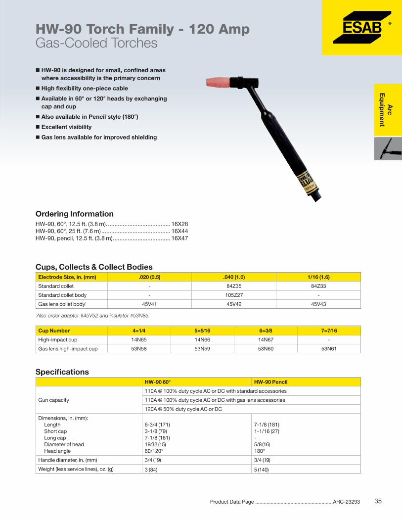
� HW-90 is designed for small, confined areas where accessibility is the primary concern
� High flexibility one-piece cable
� Available in 60° or 120° heads by exchanging cap and cup
� Also available in Pencil style (180°)
� Excellent visibility
� Gas lens available for improved shielding
Ordering Information HW-90, 60°, 12.5 ft. (3.8 m). ...................................... 16X28HW-90, 60°, 25 ft. (7.6 m) .......................................... 16X44HW-90, pencil, 12.5 ft. (3.8 m) ................................... 16X47
Without Gas ValveHW-9, 70°, 1pc cable assembly, 12.5 ft. (3.8 m) ........ 19684HW-9, 70°, 1pc cable assembly, 25 ft. (7.6 m) ........... 19685HW-9F, 70°, 1pc cable assembly, 12.5 ft. (3.8 m) ...... 19922HW-9F, 70°, 1pc cable assembly, 25 ft. (7.6 m) ......... 19923
With Gas ValveHW-9F, 70°, 1pc cable assembly, 25 ft. (7.6 m) ......... 19611HW-9R, 70°, 2pc cable/hose assembly, 12.5 ft. (3.8 m) .. 34561HW-9R, 70°, 2pc cable/hose assembly, 25 ft. (7.6 m)...... 34562
F = Flex Head. R = Silicon Rubber.
Arc
Eq
uipm
ent
37Product Data Page .......................................................ARC-23295
� Quick release of electrodes
� Hard body provides superior heat and abrasion resistance for longest life
� Silicon rubber body provides improved resistance to breakage in rough duty
� Flexible head models provide added versatility for welding in hard-to-reach applications
Torch AssembliesHW-17, 60°, 1pc cable/hose, 12.5 ft. (3.8 m) ............. 16X48HW-17, 60°, 2pc cable/hose, 12.5 ft. (3.8 m) ............. 33855HW-17, 60°, 2pc cable/hose/twistlock, 12.5 ft. (3.8 m) . 35782HW-17, 60°, 1pc cable/hose, 25 ft. (7.6 m) ................ 16X50HW-17, 60°, 2pc cable/hose, 25 ft. (7.6 m) ................ 33856HW-17, 90°, 1pc cable/hose, 25 ft. (7.6 m) .............. 634720HW-17F, 60°, 1pc cable/hose, 12.5 ft. (3.8 m) ........... 19881
Torch Assemblies with Slide ValveHW-17, 60°, 1pc cable/hose, 12.5 ft. (3.8 m) ........... 634705HW-17, 60°, 1pc cable/hose, 25 ft. (7.6 m) .............. 634706HW-17, 90°, 1pc cable/hose, 25 ft. (7.6 m) .............. 601152
Torch Assemblies with Rotary ValveHW-17, 60°, 1pc cable/hose, 12.5 ft. (3.8 m) ......... 16X48LVHW-17, 60°, 2pc cable/hose/twistlock, 12.5 ft. (3.8 m) . 35857HW-17, 60°, 1pc cable/hose, 25 ft. (7.6 m) ............ 16X50LVHW-17, 60°, 2pc cable/hose/twistlock, 25 ft. (7.6 m) 35856HW-17R, 60°, 1pc cable/hose, 12.5 ft. (3.8 m) ......634705RHW-17R, 60°, 2pc cable/hose, 12.5 ft. (3.8 m) ........33813RHW-17R, 60°, 1pc cable/hose, 25 ft. (7.6 m) .........634706RHW-17R, 60°, 2pc cable/hose, 25 ft. (7.6 m) ...........33814RHW-17F, 60°, 1pc cable/hose, 12.5 ft. (3.8 m) ........... 19882HW-17F, 60°, 1pc cable/hose, 25 ft. (7.6 m) .............. 19884HW-17F, 60°, torch outfit ......................................... 600997
F = Flex Head. R = Silicon Rubber.
Arc
E
qui
pm
ent
38 Product Data Page .......................................................ARC-23296
� Quick release of electrodes
� Hard body provides superior heat and abrasion resistance for longest life
� Silicon rubber body provides improved resistance to breakage in rough duty
� Flexible head models provide added versatility for welding in hard-to-reach applications
Torch AssembliesHW-26, 75°, 1pc cable/hose, 12.5 ft. (3.8 m) ............. 17137HW-26, 75°, 2pc cable/hose, 12.5 ft. (3.8 m) ............. 33857HW-26, 75°, 1pc cable/hose, 25 ft. (7.6 m) ................ 46V29HW-26, 75°, 2pc cable/hose, 25 ft. (7.6 m) .............. 948127HW-26F, 75°, 1pc cable/hose, 12.5 ft. (3.8 m) ........... 33848HW-26F, 75°, 1pc cable/hose, 25 ft. (7.6 m) .............. 33849
F = Flex Head. R = Silicon Rubber.
Torch Assemblies with Rotary ValveHW-26, 75°, 1pc cable/hose, 12.5 ft. (3.8 m) ............. 17138HW-26, 75°, 2pc cable/hose/twistlock, 12.5 ft. (3.8 m) . 35858HW-26, 75°, 1pc cable/hose, 25 ft. (7.6 m) ................ 46V27HW-26, 75°, 2pc cable/hose, 25 ft. (7.6 m) .............. 948128HW-26R, 75°, 1pc cable/hose, 12.5 ft. (3.8 m) ........17138RHW-26R, 75°, 1pc cable/hose, 25 ft. (7.6 m) ...........46V27RHW-26R, 75°, 2pc cable/hose, 25 ft. (7.6 m) .........948128RHW-26F, 75°, 1pc cable/hose, 12.5 ft. (3.8 m) ........... 33850HW-26F, 75°, 2pc cable/hose, 12.5 ft. (3.8 m) ........... 33852HW-26F, 75°, 1pc cable/hose, 25 ft. (7.6 m) .............. 33851HW-26F, 75°, 2pc cable/hose, 25 ft. (7.6 m) .............. 33853
Arc
Eq
uipm
ent
39Product Data Page .......................................................ARC-23297
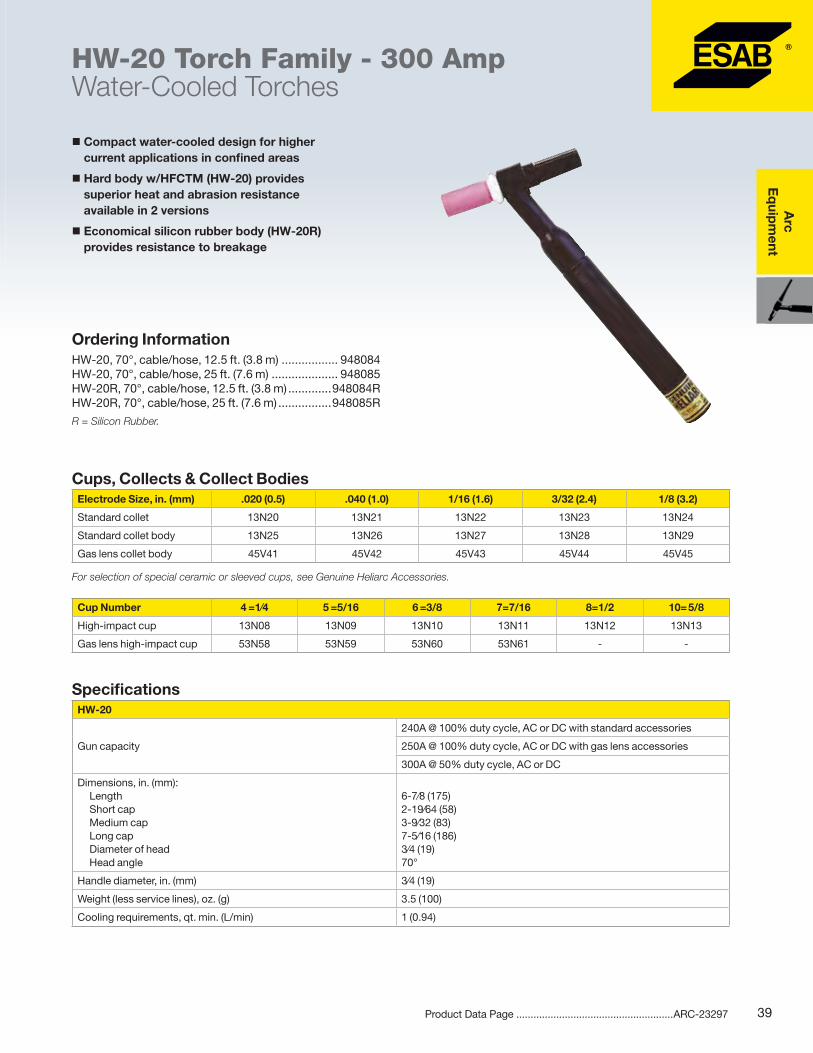
HW-20 Torch Family - 300 AmpWater-Cooled Torches
� Compact water-cooled design for higher current applications in confined areas
� Hard body w/HFCTM (HW-20) provides superior heat and abrasion resistance available in 2 versions
� Economical silicon rubber body (HW-20R) provides resistance to breakage
Ordering InformationHW-20, 70°, cable/hose, 12.5 ft. (3.8 m) ................. 948084HW-20, 70°, cable/hose, 25 ft. (7.6 m) .................... 948085HW-20R, 70°, cable/hose, 12.5 ft. (3.8 m) .............948084RHW-20R, 70°, cable/hose, 25 ft. (7.6 m) ................948085R
40 Product Data Page .......................................................ARC-23298
HW-18 Torch Family - 425 AmpWater-Cooled Torches
� The industry standard water-cooled general purpose torch
� Ideal for production welding
� Lightweight - reduces operator fatigue
�Water-tight - brazed, closed cooling system
� Gas lens available for improved shielding
� Hard body w/HFCTM (HW-18) provides superior heat and abrasion resistance for the longest life
� Economical silicon rubber body (HW-18R) provides resistance to breakage
Ordering InformationHW-18, 60°, cable/hose, 12.5 ft. (3.8 m) ................. 948361HW-18, 60°, cable/hose, 25 ft. (7.6 m) .................... 948362HW-18R, 60°, cable/hose, 12.5 ft. (3.8 m) .............948361RHW-18R, 60°, cable/hose, 25 ft. (7.6 m) ................948362R
R = Silicon Rubber.
Specifications HW-18
Gun capacity
300A @ 100% duty cycle, AC or DC with standard accessories
375A @ 100% duty cycle, AC or DC with gas lens accessories
425A @ 50% duty cycle, AC or DC
Dimensions, in. (mm)LengthShort capMedium capLong capDiameter of headHead angle
Standard collet body 10N29 10N30 10N31 10N32 10N28
Gas lens collet body 45V29 45V24 45V25 45V26 45V27
Lrg. diameter lens collet body - - - 45V64 995795
Cup Number 4 =1⁄4 5 =5/16 6 =3/8 7=7/16 8=1/2 10= 5/8 12=3/4 Short
High-impact cup 10N50 10N49 10N48 10N47 10N46 10N45 10N44 -
Gas lens high-impact cup 54N18 54N17 54N16 54N15 54N14 - - 54N19
Lrg. dia. gas lens, high-impact cup - - - - - 53N88 53N87 53N89
Arc
Eq
uipm
ent
41Product Data Page .......................................................ARC-23299
� Small, lightweight
� Flexible head to access difficult joints
HW-25 Torch Family - 200 AmpWater-Cooled Torches
Ordering InformationHW-25, cable assembly, 12.5 ft. (3.6 m) .................... 45V36HW-25, cable assembly, 25 ft. (7.6 m) ....................... 45V37
Specifications HW-25
Gun capacity200A @ 100% duty cycle, AC or DC with standard accessories
210A @ 50% duty cycle, AC or DC with standard or gas lens
Dimensions, in. (mm):LengthLength of headDiameter of headHead angle
Standard collet body 13N25 13N26 13N27 13N28 13N29
Gas lens collet body 45V41 45V42 45V43 45V44 45V45
Cup Number 4 =1⁄4 5 =5/16 6 =3/8 7=7/16 8=1/2 10= 5/8
High-impact cup 13N08 13N09 13N10 13N11 13N12 13N13
Gas lens high-impact cup 53N58 53N59 53N60 53N61 - -
Arc
E
qui
pm
ent
42 Product Data Page .......................................................ARC-23300
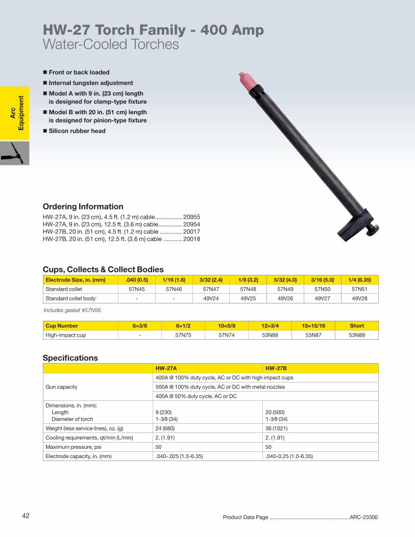
� Front or back loaded
� Internal tungsten adjustment
�Model A with 9 in. (23 cm) length is designed for clamp-type fixture
�Model B with 20 in. (51 cm) length is designed for pinion-type fixture
� Silicon rubber head
HW-27 Torch Family - 400 AmpWater-Cooled Torches
Ordering InformationHW-27A, 9 in. (23 cm), 4.5 ft. (1.2 m) cable ................ 20955HW-27A, 9 in. (23 cm), 12.5 ft. (3.6 m) cable .............. 20954HW-27B, 20 in. (51 cm), 4.5 ft. (1.2 m) cable ............. 20017HW-27B, 20 in. (51 cm), 12.5 ft. (3.6 m) cable ........... 20018
Specifications HW-27A HW-27B
Gun capacity
400A @ 100% duty cycle, AC or DC with high impact cups
500A @ 100% duty cycle, AC or DC with metal nozzles
400A @ 50% duty cycle, AC or DC
Dimensions, in. (mm):LengthDiameter of torch
9 (230) 1-3⁄8 (34)
20 (500)1-3⁄8 (34)
Weight (less service lines), oz. (g) 24 (680) 36 (1021)
44 Product Data Page .......................................................ARC-23301
Genuine Heliarc®
Accessories
Gas Lens To meet increasingly stringent weld quality standards, we developed the patented GENUINE HELIARC Gas Lens. This stack of con centric, fine-mesh stainless steel screens produces an exceptionally stable stream of shielding gas (see Figure 1). By forcing the gas into a coherent stream, an effective shielding pattern can be projected greater distances (see Figure 2).
Patented Genuine Heliarc Gas Lens Conventional Torch
FIG. 1 FIG. 2
Welding is possible at nozzle distances up to 1 in. from the plate surface, allowing greater welder visibility and access to tight joints.
Extending the electrode from the gas cup also increases the current capacity of some torch models. For example, a gas lens increases the 100 percent duty rating of our popular Heliarc HW-18 torch from 300 to 375A.
Arc
Eq
uipm
ent
45Product Data Page .......................................................ARC-23301
Genuine Heliarc®
Accessories
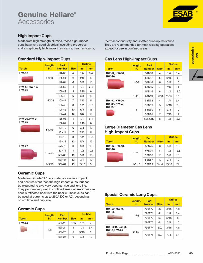
High Impact Cups Made from high strength alumina, these high-impact cups have very good electrical insulating properties and exceptionally high impact resistance, heat resistance,
Standard High-Impact Cups
TorchLength,
in.Part
Number Size
Orifice
in. mm
HW-90
1-5⁄16
14N65 4 1⁄4 6.4
14N66 5 5⁄16 8
14N67 6 3⁄8 10
HW-17, HW-18, HW-26
1-27⁄32
10N50 4 1⁄4 6.4
10N49 5 5⁄16 8
10N48 6 3⁄8 10
10N47 7 7⁄16 11
10N46 8 1⁄2 12.5
10N45 10 5⁄8 16
10N44 12 3⁄4 19
HW-20, HW-9, HW-25
1-5⁄32
13N08 4 1⁄4 6.4
13N09 5 5⁄16 8
13N10 6 3⁄8 10
13N11 7 7⁄16 11
13N12 8 1⁄2 12.5
13N13 10 5⁄8 16
HW-27
1-27⁄32
57N75 6 3⁄8 10
57N74 8 1⁄2 12.5
53N88 10 5⁄8 16
53N87 12 3⁄4 19
1-5⁄16 53N89 15 15/16 24
Gas Lens High-Impact Cups
TorchLength,
in. Part
Number Size
Orifice
in. mm
HW-17, HW-18, HW-26
1-5/8
54N18 4 1/4 6.4
54N17 5 5/16 8
54N16 6 3/8 10
54N15 7 7/16 11
54N14 8 1/2 12.5
1-1/8 54N19 Short 11/16 17
HW-90, HW-20, HW-24, HW-9, HW-25
1
53N58 4 1/4 6.4
53N59 5 5/16 8
53N60 6 3/8 10
53N61 7 7/16 11
53N61S 8 1/2 12.7
Large Diameter Gas Lens High-Impact Cups
TorchLength,
in.Part
Number Size
Orifice
in. mm
HW-17, HW-18, HW-26
1-7/8
57N75 6 3/8 10
57N74 8 1/2 12.5
53N88 10 5/8 16
53N87 12 3/4 19
1-5/16 53N89 Short 15/16 24
Ceramic Cups Made from Grade “A” lava materials are less impact and heat resistant than the high-impact cups, but can be expected to give very good service and long life. They perform very well in confined areas where excessive heat is reflected back into the nozzle. These cups can be used at currents up to 250A DC or AC, depending on arc time and cup size.
Ceramic Cups
TorchLength,
in.Part
Number Size
Orifice
in. mm
HW-24
5/8
53N23 .165 .165 4
53N24 4 1/4 6.4
53N25 5 5/16 8
53N27 6 3/8 10
Special Ceramic Long Cups
TorchLength,
in.Part
Number Size
Orifice
in. mm
HW-20, HW-9, HW-25
1-7/8
796F70 3L 3/16 4.8
796F71 4L 1/4 6.4
796F72 5L 5/16 8
796F73 6L 3/8 10
HW-20 (X-Long), HW-9, HW-25
2-1/2
796F74 3XL 3/16 4.8
796F75 4XL 1/4 6.4
thermal conductivity and spatter build-up resistance. They are recommended for most welding operations except for use in confined areas.
Arc
E
qui
pm
ent
46 Product Data Page .......................................................ARC-23301
Each spare parts kit contains those accessory items most requested by our customers for use on our most popular GTAW torches, in easy-to-order kit form, packaged in durable plastic boxes.
Genuine Heliarc®
Accessories
54N63
53N66 598882
54N8554N01
45V52
Adaptors & Accessories Description Part Number Used On
Insulator 54N63 HW-17,18, 26
Insulator 54N01 HW-17, 18, 26
Insulator 53N85 HW-90
Adaptor 45V52 HW-90
Collet body insulator
53N66 HW-24
Cup gasket 598882 HW-20, 9
TIG torch holder 0760022400 All
45V11-LH 45V62-RH 0760022400
53N43105Z57
Spare Parts Kit
Description
999126 HW-17, 18, 26 TXH-151, 201
999127 HW-20
TXH-121, 251w999124 HW-90
0558101886TXH-401w Quantity
Short torch cap 57Y04 - - 57Y04 1
Long torch cap - 41V24 56Y40 - 1
Collet .040 in. (1.0 mm) - - 84Z35 - 1
Collet 1/16 in. (1.6 mm) 10N23 13N22 84Z33 10N23 1
Collet 3/32 in. (2.4 mm) 10N24 13N23 - 0157123077 1
Collet 1/8 in. (1.4 mm) 10N25 13N24 - 0157123078 1
Collet body, .040-3/32 in. (1.0-2.4 mm) 0157123081
Collet body, 1/8-3/16 in. (3.2-5.0 mm) 0157123082
Collet body, 1/16 in. (1.6 mm) 10N31 13N27 - - 1
Collet body, 3/32 in. (2.4 mm) 10N32 13N28 - - 1
Collet body, 1/8 in. (1.4 mm) 10N28 13N29 - - 1
High-impact cup No. 4 - - 14N65 - 1
High-impact cup No. 5 10N49 13N09 14N66 - 1
High-impact cup No. 6 10N48 13N10 14N67 54N16 1
High-impact cup No. 7 - 13N11 - 54N15 1
High-impact cup No. 8 10N46 - - 54N14 1
.040 in. dia. x 7 in. long, Ground Finish Tungsten Electrode - - Q796F55 - 1
1/16 in. dia. x 7 in. long, Ground Finish Tungsten Electrode Q796F58 Q796F58 Q796F58 Q796F58 1
3/32 in. dia. x 7 in. long, Ground Finish Tungsten Electrode Q796F63 Q796F63 Q796F63 1
1/8 in. dia. x 7 in. long, Ground Finish Tungsten Electrode Q796F68 Q796F68 Q796F68 1
Power Cable Adaptors Description Part Number Used On
Adaptor 53N43 HW-90, 24
Adaptor 105Z57 HW-17, 9
Adaptor 45V11 HW-18, 20
Adaptor 45V62 HW-26
Fuse assembly 45V34 HW-18, 20
Replacement fuses (5/pk)
54N26 , 25A 54N30, 60A
HW-18, 20
Arc
Eq
uipm
ent
47Product Data Page .......................................................ARC-23301
Genuine Heliarc®
Accessories
Electrodes - Ground Finish Provides Maximum Smoothness
Diameter, in. (mm)
Length, in. (mm)
Pure (EWP)
Green Coded
Zirconiated (EWZr-1)
Brown Coded 2% Ceriated (EWCe-2)
Orange Coded1.5% Lanthana (EWG)
Gray Coded
.040 (1.0) 7 (175) - - - Q796F55
1/16 (1.6) 7 (175) Q76Z51 Q790F47 Q798F92 Q796F58
3/32 (2.4) 7 (175) Q76Z57 Q790F48 Q798F93 Q796F63
1/8 (3.2) 3 (75) - - - Q796F66
7 (175) Q76Z52 Q790F49 Q798F94 Q796F68
5/32 (4.0) 7 (175) Q81Z43 Q790F50 Q798F95 Q796F84
3/16 (5.0) 7 (175) - Q790F51 - -
Additional electrodes are available. For ordering information consult your ESAB Sales Representative or Distributor. Each package contains ten electrodes. For additional accessories, consult the Genuine Heliarc® Torch Guide #ARC-23110, available for download at esabna.com.
Hoses/Cable Sheaths Description Part Number Used On
Zippered Nylon
12.5 ft. x 3 in. wide 35453 All
25 ft. x 3 in. wide 35454 All
Non-Zippered
9 ft. x 7/8 in. I.D. 2075198 HW-20
20 ft. x 7/8 in. I.D. 2075200
9 ft. x 1-1/4 in. I.D. 2075199 HW-18
10 ft. leather with snaps 6 in. wide
20812
Widths are as flat.
34015
57Y04
57Y02
84Z31
56Y40
41V35
41V24
41V33
Back Caps Description Part Number Used On
Short cap 41V33 HW-20, 9 TXH-121, 251w
Medium cap 41V35 HW-20, 9 TXH-121, 251w
Long cap 57Y02 HW-17, 18, 26TXH-151, 201
Medium cap 34015 HW-17, 18, 26TXH-151, 201
Short cap 57Y04 HW-17, 18, 26TXH-151, 201
Short cap 84Z31 HW-90
Long cap 56Y40 HW-90
Arc
E
qui
pm
ent
48Instruction Manual ...................................................... 0463330031Product Data Page .......................................................ARC-23290
Includes: power source with 10 ft. (3 m) power cord, 115/230V input power adapter cable, 10 ft. (3 m) heavy-duty ground cable and clamp, 10 ft. (3 m), heavy-duty electrode holder and cable, and sample pack of ESAB electrodes.
GTAW Package also includes HW-17FV torch, R33 reg/flowmeter, and GTAW accessory kit.
Options & AccessoriesWelding cable 200A, 16.4 ft. (5 m) OKC25....... 0700006882Return cable 200A, 16.4 ft. (5 m) OKC25 ......... 0700006883GTAW torch, 17FV, 20 ft. (6 m) & accessory kit 0558101723R33-FM-580 regulator/flowmeter ............................. 21557GTAW torch accessory kit ....................................... 999126
� The MiniArc 161LTS Automatic Primary Select operates on either 115V or 230V and will automatically configure to the primary input supplied
� Fixed hot start - allows the operator to easily strike an arc without the electrode sticking to the plate
� Fixed arc force - allows the operator to get deeper penetration into the plate without the electrode sticking to the plate
� LiftArc™ TIG gives you the luxury of lifting the tungsten as opposed to traditional scratch starting which can deposit tungsten into the plate resulting in contamination
� Able to use cellulosic 6010 electrodes with ease
� 18 lbs. (13.6 kg) weight - makes this unit portable and easy to carry directly to the job
� Comes with a shoulder strap
� Includes 10 ft. (3 m) work cable with clamp, and 10 ft. (3 m) welding cable with electrode holder
� Thermal indicator prevents the machine from exceeding the duty cycle and from becoming damaged if airflow is blocked
� Simple interface - amperage knob, process switch and on/off switch on front panel of unit
Dimensions, LxWxH, in. (mm) 15.75x5.75x10 (400x146x255) 15.75x5.75x10 (400x146x255)
Arc
Eq
uipm
ent
49Instruction Manual ...................................................... 0460446001Product Data Page .......................................................ARC-23251
� Caddy Arc features built-in, advanced inverter technology to deliver unparalleled performance in a rugged, portable package
� Adjustable hot start makes it easy to strike the electrode and avoid starting problems
� Adjustable arc force sets the intensity of the arc improving weld quality
� ArcPlus II improves welding characteristics and simplifies work producing better weld quality with less clean up
� Caddy Arc supplies direct current and allows you to weld most metals including alloy and non alloy steel, stainless steel and cast iron. The Caddy Arc 201i welds electrodes up to 5/32 diameter
� For GTAW applications with the Caddy Arc, all you need is a torch with a gas valve, gas regulator, and cylinder of gas
� Features compact design with impact resistant polymer and aluminum casing – makes the unit lightweight and easy to carry
� Small size does not compromise vital cooling of internal components
� Large heat sinks and innovative design make this Caddy machine run cooler – promotes longer machine life even when used in harsh environments
� Built in accordance with IP 23 for outdoor use, even in wet-weather conditions – makes this machine ideal for on-site work
� Equipped with a PFC (Power Factor Correction) circuit – allows the machine to perform a full range of functions on a 16 A fuse, protects against fluctuating input voltage, and makes it safer to use with a generator
� The advanced Caddy A33 panel features digital display with hot-start and arc force control for fine tuning, SMAW or GTAW selection, LiveTig start, two memory settings and remote control
2-Wheel TrolleySmall gas bottle ............................................. 0459366885Gas bottle on side ........................................... 0460330880
Remote ControlsMMA 1, 33 ft. (10 m) cable ............................... 0349501024AT 1 ................................................................. 0459491896AT1 CoarseFine .............................................. 0459491897
Connection Cables for AT1 and AT1 CoarseFine16.4 ft. (5 m) ................................................... 045955288033 ft. (10 m) .................................................... 045955288149 ft. (15 m) .................................................... 045955288282 ft. (25 m) .................................................... 0459552883
Remote foot control, 25 ft. (7.6 m) cable1 ......... 0558008905Torch remote, 25 ft. (7.6 m)1 ............................. 05580089041For use with A33 models only.
GTAW TorchesTXH-151V, 13 ft. (4 m), OKC50 ....................... 0700300539TXH-151V, 26 ft. (8 m), OKC50 ........................ 0700300545TXH-201V, 13 ft. (4 m, OKC50) ........................ 0700300553TXH-201V, 26 ft. (8 m), OKC50 ........................ 0700300556
V = Gas Valve.
Arc
Eq
uipm
ent
51Instruction Manual ...................................................... 0349301163Product Data Page .......................................................ARC-23282
Origo™ Arc 410c & 650c
� Sturdy, robust switching converter (chopper) power sources intended for manual heavy-duty welding processes - SMAW (with coated electrodes), GTAW, and air carbon arc gouging (ACAG)
� These machines are built with proven technology, for the highest level of reliability and outstanding welding performance
� Strong metal housing makes Origo Arc ideal for use in harsh industrial environments
�Wide current range makes it easy to optimize settings, allowing the machine to be used with an extensive range of consumables
� These units are equipped with functions such as hot start, arc force, and anti-stick; also adjust parameters during the welding process
� The units have vertical static characteristics, which means that regardless of cable length and arc voltage, the current remains constant
� The dynamic characteristics of the Origo Arc ensure a stable, spatter-free arc, and an easily controlled molten pool
� Due to the high power factor, energy consumption is low, and installation costs can be kept to a minimum
� The welding properties of the Origo Arc units are configured to meet the requirements of welding with cellulosic electrodes
� The arc is very flexible when starting from the lowest currents
�When the arc is shortened, arc force makes weld penetration easier - especially when the electrode is pressed against the welded material
� Origo Arc 410c and 650c are equipped with the A12 control panel - a full-featured control panel with a V/A instrument and a receiver for wireless current setting
� As an option, the Origo Arc range can be equipped with remote control
Remote Connection Cables16.4 ft. (5 m) analog 12 pole ............................ 045955288033 ft. (10 m) analog 12 pole ............................. 045955288149 ft. (15 m) analog 12 pole ............................. 045955288282 ft. (25 m) analog 12 pole ............................. 0459552883
Welding & Work CablesWelding cable, 16.4 ft. (5m) OKC95, 500A ...... 0700006894Return cable,16.4 ft. (5 m) OKC95, 500A ........ 0700006895
Arc
E
qui
pm
ent
52Instruction Manual ...................................................... 0349301163Product Data Page .......................................................ARC-23282
Origo™ Arc 410c & 650c
Specifications Origo Arc 410c Origo Arc 650c
Input voltage 230/460/550V, 3,ph, 60Hz1 230/460V, 3,ph, 60,Hz
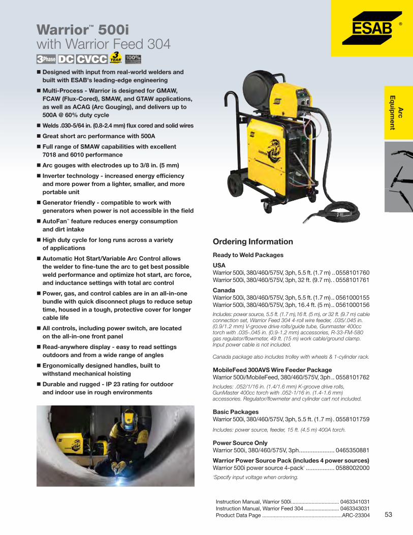
USAWarrior 500i, 380/460/575V, 3ph, 5.5 ft. (1.7 m) ..0558101760Warrior 500i, 380/460/575V, 3ph, 32 ft. (9.7 m). . 0558101761
CanadaWarrior 500i, 380/460/575V, 3ph, 5.5 ft. (1.7 m) .. 0561000155Warrior 500i, 380/460/575V, 3ph, 16.4 ft. (5 m) .. 0561000156
Includes: power source, 5.5 ft. (1.7 m),16 ft. (5 m), or 32 ft. (9.7 m) cable connection set, Warrior Feed 304 4-roll wire feeder, .035/.045 in. (0.9/1.2 mm) V-groove drive rolls/guide tube, Gunmaster 400cc torch with .035-.045 in. (0.9-1.2 mm) accessories, R-33-FM-580 gas regulator/flowmeter, 49 ft. (15 m) work cable/ground clamp. Input power cable is not included.
Canada package also includes trolley with wheels & 1-cylinder rack.
Includes: .052/1/16 in. (1.4/1.6 mm) K-groove drive rolls, GunMaster 400cc torch with .052-1/16 in. (1.4-1.6 mm) accessories. Regulator/flowmeter and cylinder cart not included.
Basic PackagesWarrior 500i, 380/460/575V, 3ph, 5.5 ft. (1.7 m) . 0558101759
Includes: power source, feeder, 15 ft. (4.5 m) 400A torch.
Power Source OnlyWarrior 500i, 380/460/575V, 3ph ..................... 0465350881
Warrior Power Source Pack (includes 4 power sources)Warrior 500i power source 4-pack1 ................. 05880020001Specify input voltage when ordering.
Warrior™ 500iwith Warrior Feed 304
� Designed with input from real-world welders and built with ESAB's leading-edge engineering
�Multi-Process - Warrior is designed for GMAW, FCAW (Flux-Cored), SMAW, and GTAW applications, as well as ACAG (Arc Gouging), and delivers up to 500A @ 60% duty cycle
� Welds .030-5/64 in. (0.8-2.4 mm) flux cored and solid wires
� Great short arc performance with 500A
� Full range of SMAW capabilities with excellent 7018 and 6010 performance
� Arc gouges with electrodes up to 3/8 in. (5 mm)
� Inverter technology - increased energy efficiency and more power from a lighter, smaller, and more portable unit
� Generator friendly - compatible to work with generators when power is not accessible in the field
� AutoFan™ feature reduces energy consumption and dirt intake
� High duty cycle for long runs across a variety of applications
� Automatic Hot Start/Variable Arc Control allows the welder to fine-tune the arc to get best possible weld performance and optimize hot start, arc force, and inductance settings with total arc control
� Power, gas, and control cables are in an all-in-one bundle with quick disconnect plugs to reduce setup time, housed in a tough, protective cover for longer cable life
� All controls, including power switch, are located on the all-in-one front panel
� Read-anywhere display - easy to read settings outdoors and from a wide range of angles
� Ergonomically designed handles, built to withstand mechanical hoisting
� Durable and rugged - IP 23 rating for outdoor and indoor use in rough environments
Counterbalance MiniBoomFor 12 in. (305 mm) spools .............................. 0458705880For 18 in. (457 mm) spools .............................. 0458705882
Extension arm for 60-lb coil (18 in. spools) ...... 0459233880Coil adaptor for 60-lb (27.2-kg) coils1 ........................ 34323Female gas hose quick-connector .................. 0365803002Gas flow checker ...................................................... 19043PrecisionMaster gas saver kit ......................... 0558007079Remote kit, Warrior power source ................... 04654248801Requires extension arm #0459233880.
Connection Cable Sets, Air-Cooled Torch5.6 ft. (1.7 m) ................................................... 045983688032.8 ft. (10 m) .................................................. 045983688249.2 ft. (15 m) .................................................. 045983688382 ft. (25 m) ..................................................... 0459836884
Control Panel
Power On/Off
Wire Feeder Connector
Resettable Circuit Breaker
Output Power Connectors
Process Selector
Automatic Hot Start/ Variable Arc Control
Output Voltage/Current Control
Over Temperature LEDVRD LED
Digital Volt / Amp Meter
Stick Mode Selector
Power Source AccessoriesAuto transformer, 208/230/460V, 3ph ............. 0588002040
Electrode Holder Assemblies175A, 15 ft. (4.5 m) .......................................... 0558001791300A, 15 ft. (4.5 m) .................................................... 21226
Remote ControlsRemote kit ...................................................... 0465424880FS003-B remote foot control, 25 ft. (7.6 m) ..... 0558008905RCA-2B remote torch control, 25 ft. (7.6 m) .... 0558008904Remote control AT1 analog ............................. 0459491896Remote control AT1 course-fine analog1 ......... 0459491897Cable interconnect analog 12P, 16.4 ft. (5 m) .. 0459552880Cable interconnect analog 12P, 33 ft. (10 m) ... 0459552881Cable interconnect analog 12P, 50 ft. (15 m) ... 0459552882Cable interconnect analog 12P, 82 ft. (25 m) ... 0459552883Warrior 500i spool gun option ......................... 0588002061Remote adaptor kit, Miggytrac/Railtrac .......... 04654518801Order cable separately.
Work Cable Extensions16.4 ft. (5 m) - 2/0 AWG ................................... 055810187833 ft. (10 m) - 2/0 AWG .................................... 055810187950 ft. (15 m) - 2/0 AWG .................................... 055810188082 ft. (25 m) - 2/0 AWG .................................... 055810188182 ft. (25 m) - 4/0 AWG .................................... 0558101882115 ft. (35 m) - 4/0 AWG ................................... 0558101883
Warrior Feed 304 has 4-roll drive system and 19 pole amphenol cable connection. Includes digital meters, .035/.045 in. (0.9/1.2 mm) V-groove drive rolls/guide tube and spool enclosure. 1Includes water solenoid connections. 2Special order upon request.
Feed Roll KitsV-Groove .023-.030 in. (0.6-0.8 mm) ............... 0558003134 V-Groove .035-.045 in. (0.9-1.14 mm) ............. 0558003135V-Groove .052-.1/16 in. (1.3-1.6 mm) .............. 0558003136K-Groove 035-.045 in. (0.9-1.14 mm) ............. 0558003137K-Groove 045-.052 in. (1.14-1.3 mm) ............. 0558003138K-Groove 1/16-5/64 in. (1.6-2.0 mm) .............. 0558003139
GMAW TorchesGunMaster 400cc, 25 ft. (7.6 m) basic ............. 0558001674GunMaster 400cc,12 ft. (3.6 m) x .035-.045 in. 0558001667GunMaster 400cc,15 ft. (4.5 m) x .035-.045 in. 0558001669GunMaster 400cc,15 ft. (4.5 m) x .052-1/16 in. 0558001670
GTAW TorchesHW-17V-2TL, 12.5 ft. (3.6 m) ..................................... 35857HW-17V-2TL, 25 ft. (7.6 m) ........................................ 35856HW-26V-2TL, 12.5 ft. (3.6 m) ..................................... 35858HW-17, 18, 26 accessory kit ................................... 999126
V = Gas Valve.
Gouging TorchQ4000 gouging torch package, 10 ft. (3 m) ....Q61-082-009
Warrior 500i can be paralleled to utilize larger gouging rods.Mobilefeed 300 AVS 4-Roll Suitcase Wire Feeder Mobilefeed 300 AVS LC-40 ............................. 0558005729
This optional wire feeder includes digital meter, gas solenoid valve, contactor, LC-40 male connector and .045-1/16 in. (1.2-1.6 m) serrated drive rolls.
Warrior™ 500iwith Warrior Feed 304
Warrior Feed 304 Wire Feeder Data
Power Supply
Wire Spool Capacity, lbs. (kg)
Max. Spool Diameter, in. (mm)
Wire Feed Speed, ipm (m/min)
Dimensions (LxWxH), in. (mm)
Weight Enclosed, lbs. (kg) Wire Dimensions, in. (mm)
42 VAC, 50/60 Hz
44 (18) 12 (300)1 32-1000 (0.8-25) 27 x11x16(690 x 275 x 420)
� The Origo Mig 652c meets the demands of the cost-conscious fabricator for high productivity, versatility, and high quality production with low overall welding costs
� The wide current and voltage range together with stepless, dial adjusted inductance make it easy to optimize settings for a wide variety of filler metals and gases
�Multi-voltage - ready to work anywhere
� Robust power technology and digital V/A meter
� Stepless voltage control - for precise settings and remote control (optional)
� Large wheels, undercarriage and sturdy lifting eyelets allow the Origo Mig 652c to be lifted by a forklift
� Sturdy galvanized metal casing with air filter (optional)
� Durable and rugged - IP 23 rating for outdoor and indoor use in rough environments
Includes: power source, 16.4 ft. (5 m) work cable, wheels, gas bottle platform and guide pin for wire feeder.
*Available in USA only.
SpecificationsOrigo Mig 652c
Input voltage 230/440-460V, 3ph, 60Hz
Permitted load at:60% duty cycle100% duty cycle
650A/41V 500A/39V
Setting range (DC): GMAWSMAWGTAW
40-320A/16-30V 14-650A/20-44V21-650A/20-44V
Open circuit voltage 53-60V
Open circuit power 670W
Power factor at maximum current 0.90
Efficiency at maximum current 76%
Control voltage 42V, 50/60Hz
Dimensions, LxWxH, in. (mm) 33x26x33 (830x640x835)
Weight, lbs. (kg) 502 (228)
Operating temperature, °F (°C) 14 to 104 (-10 to 40)
Enclosure class IP 23
Options & AccessoriesOrigo Feed 304 M13u wire feeder ................... 0459115860Air filter............................................................ 0349302252Electrode holder assembly QC, 15 ft. (4.5 m) ............ 21226Power source strain relief for connection cables .. 0349311700Cable and torch holder ................................... 0349303362Dual cylinder tray kit ........................................ 0349312780
Work Cable Assemblies15 ft. (4.5 m) w/clamp OKC50 ................................... 3625332 ft. (9.8 m) w/clamp OKC50 ......................... 0558001906
Connection Cable Sets, Air-Cooled Torch5.6 ft. (1.7 m) ................................................... 034931246016.4 ft. (5 m) .................................................... 034931246133 ft. (10 m) ..................................................... 034931246249 ft. (15 m) ..................................................... 034931246382 ft. (25 m) ..................................................... 0349312464115 ft. (35 m) ................................................... 0349312465
Includes: control cable, electrode cable, and gas hose.
Origo Feed 304 M13u � Remote voltage control, allows local setting of power source voltage output
�Wire feed speed, accurate graduated dial shows settings in 50 ipm (1 m/min) increments
� Adjustable burn-back time to correct stick-out and reduce wear of contact tips
� 2/4 stroke, helps minimize operator fatigue by optionally selecting trigger lock in the 4-stroke mode
� Inching/Gas Purge - inching eliminates unsafe trigger pulls to load wire; gas purge ensures a clean start with pure shield gas
� Creep start - simplifies start/stop and gradual feed of wire to optimize the starts.
� Quick connectors - shortest possible set-up times; no tools required to change feed rolls, connect gas hose, weld cable or control cable
�With its galvanized metal casing, the Origo Feed is ideal for use in tough environments
� Electronically controlled feeding gives accurate and stable arc
� The four wheel roll feeder mechanism with grooves in both feed roll and pressure roll gives stable feeding and low wear on the wire - to avoid operational disturbance
� The feeders are available with either 1.18 in. (30 mm) rolls for wires from .023 in. (0.6 mm) up to 5/64 in. (2.0 mm)
� All operating adjustments are made on the front panel of the feeder, giving a good overview of the settings
� The front panel of the M13u is equipped with switches for inching/gas purge, 2/4 stroke and creep start
� A wire feed speed knob with accurate graduated dial and adjustable burn-back are included
� A remote voltage control is provided with 10 graduations from min. to max. settings
� The panel is easy to operate with accurate setting that suits different needs and demands
� Extra versatility can be provided by utilizing one of the following mounting options for the Origo Feed: counterbalance & mast, wheel kit or hanging bracket
Ordering Information
Basic PackagesOrigo Feed 304 M13u with QC ........................ 0558101668Origo Feed 304 M13u with lugs ...................... 0558101669
Includes: feeder, 400A torch, cables, and R-33 flowmeter.
Aristo Feed units offer the ability to create synergic lines, allowing one-knob setup for welding with solid wire, cored wire, metal-cored wire, and various gas mixes. The feeder can also be set up for DC pulse and synergic pulse welding.
� All of the features from the MA24, plus...
� Ability to create up to 60 synergic lines
�Memory for 10 parameter sets
� DC pulse and synergic pulse welding
The U82 panel adds SuperPulse™ technology for exceptional heat control.
� All of the features from the U6, plus...
� 230 pre-programmed synergic lines
�Memory for 255 parameter sets
� SuperPulse – for superior control of heat input
� Remote operator pendant
� Ability to create your own synergic lines
The MA24 panel offers QSet™, a unique function that optimizes welding parameters in short arc for solid wire welding in stainless and carbon steels. Simply set the wire feed speed, and QSet will automatically select the correct welding parameters for the required wire/gas combination.
� All of the features from the MA23, plus...
� Creep start provides a softer, more direct start with less spatter
� Crater filling
� Pre-programmed synergic lines ensure optimum settings with a wide choice of materials, wire dimensions, and gas combinations
A sturdy, easy-to-use wire feeder with the features you need for reliable GMAW and SMAW applications.
� 2/4 stroke simplifies handling the welding torch
� Process select and gas pre/post flow
� Digital V/A meters
� Gas purge/wire inching
� Memory for 3 parameter sets
� Quick connectors – shorten setup times
� TrueArcVoltage™ system measures the correct arc voltage value independent of the length of the connection cable, or welding torch
230/460/575V, 3ph, ready to weld package includes: power source, 16.4 ft. (5 m) work cable/ground clamp, factory installed wheel kit, 6 ft. (1.7 m) cable connection kit, wire feeder, .035/.045 in. (0.9/1.2 mm) V-groove drive rolls/guide tube, swivel mounting post for wire feeder, gas cylinder rack, Gunmaster 400cc welding torch with .035/.045 in. (0.9/1.2 mm) accessories and gas regulator/flowmeter. Input power cable is not included.
230/460V, 3ph, ready to weld package includes: power source, wire feeder, 15 ft. (4.5 m) 400A torch, 5.5 ft. (1.7 m) connection cable set, 16.4 ft. (5 m) work cable, regulator/flowmeter Ar CO2.
Basic package includes: power source, wire feeder, 15 ft. (4.5 m) 400A torch.
.063 (1/16) C 0458825003 0459049001 0455072002 0469837880 V-K 1.6 R2
.030/.035–.040 (0.8/0.9-1.1) Al 0458824001 0455049001 0456615001 0469837880 U 0.8 A2 & 1.0 A2
3/64/.062 (1.2/1/16) Al 0458824003 0455049001 0456615001 0469837880 U 1.2 A2 & 1.6 A2
C = cored wire, K = knurled groove. 1As delivered.
Options & Accessories
Power Source AccessoriesAir filter............................................................ 0349302252Electrode holder assembly, 300A, 15 ft. (4.5 m) ........ 21226Strain relief for interconnection cables ............ 0349311700Cable and torch holder ................................... 0349303362Dual cylinder rack ........................................... 0349312780Origo Feed dual feeder manual switch ............ 0588001819Work cable & clamp, 15 ft. (4.5 m) ............................. 36253Work cable & clamp, 32 ft. (9.8 m) ................... 0558008683MMC cable to power supply.... ....................... 0458357885MMC panel A24 .............................................. 0459773887
GunMaster 400cc Torches25 ft. (7.6 m), basic .......................................... 055800167412 ft. (3.6 m) x .035-.045 in. (0.9-1.2 mm) ........ 055800166715 ft. (4.5 m) x .035-.045 in. (0.9-1.2 mm)1 ...... 055800166915 ft. (4.5 m) x .052–1/16 in. (1.4-1.6 mm) ....... 05580016701Included in standard package.
Feeder AccessoriesMarathon Pac™ inlet guide1 .............................. 0558002354Feed selector CD complete2............................ 0349311825Spool adaptor, 8 in. (203 mm), 11-lb (5 kg) SP . 0455410001Aristo Pendant U82 Plus complete w/holder ... 0460820881Aristo Pendant extension cable, 16 ft. (5 m) .... 0456280881Aristo Pendant extension cable, 33 ft. (10 m) .. 0456280882Spool cover, plastic......................................... 0458674880Spool cover, metal .......................................... 0459431880Lifting eye ....................................................... 0458706880Strain relief for welding torch .......................... 0457341881Strain relief for interconnection cable kit ......... 0459234880Counterbalance MiniBoom ............................. 0458705880Wheel kit ......................................................... 0458707880Feeder extension arm - coil adaptor ............... 0459233880
Connection Cable Kits, 10-P Amphenol
Canada (Water-Cooled)5.6 ft. (1.7 m) ..045952899016.4 ft. (5 m) ...045952899133 ft. (10 m) ....045952899250 ft. (15 m) ....045952899382 ft. (25 m) ....0459528994115 ft. (35 m) ..0459528995
Interconnection Cables CAN w/Amph 10P16.4 ft. (5 m) .................................................... 045996088033 ft. (10 m) ..................................................... 045996088182 ft. (25 m) ..................................................... 04599608821Adapts QCA conduit adaptor to feed unit. 2Requires Aristo Pendant U82 and two Aristo Feed U82 wire feeders. 3Requires remote extension cable 45996088x.
USA (Air-Cooled)5.6 ft. (1.7 m) ..034931245016.4 ft. (5 m) ...034931245133 ft. (10 m) ....034931245250 ft. (15 m) ....034931245382 ft. (25 m) ....0349312454115 ft. (35 m) ..0349312455
Arc
E
qui
pm
ent
Pla
sma
Eq
uip
men
t
64Instruction Manual ...................................................... 0459264001Product Data Page .......................................................ARC-23143
� The ideal welding package for efficient production or pre-fabrication of high demand applications with high alloyed materials
� Chassis made of extruded aluminum sections; Alutech™, a robust material that withstands rough treatment
� The power source is based on inverter IGBT technology that provides reliable equipment with outstanding welding characteristics
� The control and communication CAN-bus system means less cables, increasing operational reliability
� The power source is optimized to operate together with Aristo Feed 3004w U6 and U8 wire feeders
� Define and store customized synergic lines for any material or gas combinations; memory for 10 (U6) or 256 (U8) welding parameters
� Connection cables up to 115 ft. (35 m) provide a working radius of up to 115 ft. (35 m)
� The TrueArcVoltage™ System guarantees welding with the correct arc voltage independent of any voltage drop in the welding cables; same arc voltage and weld result whether setup with a short connection cable and 10 ft. (3 m) gun or 115 ft. (35 m) working radius
� Dust filter handles tough, dirty environments and avoids grinding-dust and metal particles inside the chassis
� Aristo SuperPulse process with the ability to control the heat input (U8 Pendant)
Aristo® Mig 5000i/U5000iwith Aristo Feed
Ordering Information
USAAristo Mig 5000i, 460V, 3ph, 60Hz .................. 0459230884Aristo Mig U5000i, 460V, 3ph, 60Hz ................ 0459230885Aristo Mig U5000iw 460V, 3ph, 60Hz1 ............. 04592308861With built-in water cooler. Work cable not included.
CanadaAristo Mig 5000i, 208-575V, 3 ph, 60Hz .....0459230880MVAristo Mig 5000iw, 208-575V, 3ph, 60Hz1 ...0459230881MV1With built-in water cooler. Aristo Mig power sources have 12-pole Burndy connector. Power source includes 16.4 ft. (5 m) work cable with ground clamp.
MMC kits for MMC panel mounted in the: Power source .................................................. 0459579880MMC - U6 ....................................................... 0458535890
Connection Cables, Water Cooled Torches5.6 ft. (1.7 m) ................................................... 045952897016.4 ft. (5 m) .................................................... 045952897133 ft. (10 m) ..................................................... 045952897249 ft. (15 m) ..................................................... 045952897382 ft. (25 m) ..................................................... 0459528974115 ft. (35 m) ................................................... 0459528975
ESAT service kit .............................................. 04588478811Includes mounting screws for separate installation. 2For current, water and shielding gas supply for 2x Aristo Feed.
Aristo Feed 3004w wire feeders have 4-roll drive system and 10-pole amphenol cable connection. Wire feeders include water kit, spool enclosure, .035/.045 in. (0.9/1.2 mm) V-groove drive rolls and guide tube. 1Aristo Feed 3004w U8 panel requires Aristo Pendant U82 Plus #0460820881.
Arc
Eq
uipm
ent
65Instruction Manual ...................................................... 0459264001Product Data Page .......................................................ARC-23143
Aristo® Mig 5000i/U5000iwith Aristo Feed
Specifications Aristo Mig 5000i, U5000i, U5000iw
Input voltage:USACanada
460V, 3ph, 60Hz208/230/460/575V, 3ph, 60Hz
Fuse slow, A 35
Setting range, DC:GMAW SMAWGTAW
16-500/8-6016-5004-500
Permitted load at: 60% duty cycle100% duty cycle
500/39400/34
Open circuit voltage, V 68-88
Energy save mode, W 50
Input power, kW 23
Power factor at max current 0.85
Efficiency at max current, % 86
Control voltage, V, Hz 42, 50/60
Dimensions, LxWxH, in. (mm):Without cooling unitWith cooling unit
25 x16 x20 (625x394x496) 25x16 x31 (625x394x776)
Enclosure class IP 23
Insulation class (main trafo.) H
Operating temperature, °F (°C) 32 to 104 (-10 to 40)
Dimensions, LxWxH, in. (mm) 25 x16 x11 (621x389x266)
MTA1 CAN
M1 10Prog CAN
Remote Control MTA1 CANProcess Knob 1 Knob 2
SMAW Current control Arc force
GTAW Pulse current Background current
GMAW 1 Wire feed speed Voltage control
GMAW 2 Wire feed speed Voltage trim +/-
Remote Control M1 10Prog CAN Process Knob 1 Switch 1 Function
GMAW 2 1-10 Memory Select Voltage trim +⁄-
Remote Control Cables - CAN Length, ft. (m) CAN 12 Pin1 CAN 10 Pin2
0.8 (0.25) 0459554884 0459960883
16.4 (5) 0459554880 0459960880
33 (10) 0459554881 0459960881
49 (15) 0459554882 -
82 (25) 0459554883 0459960882
16.4 (5) HD 0459554880 0459960880
33 (10) HD - 0459960881
82 (25) HD - 0459960882
1Used with Aristo Feed U82 & M0 wire feeders. 2Used with Aristo Feed U6 wire feeder.
Remote Controls - CAN (order cable separately)MTA1 CAN1 ..................................................... 0459491880M1 10 Program CAN2 ...................................... 04594918821Multi-function remote control for the following panels: A2, A4, TA4, TA6, MA4, MA6, U6, U8. 2Synergic MIG for MA6, U6, U8.
Arc
E
qui
pm
ent
66 Product Data Page .......................................................ARC-23185
Aristo® SuperPulse™
Innovative process for heat input control
Pulse/Pulse Pulse/Short Arc Spray/Pulse
Aristo SuperPulse is a further development of the Pulse/Pulse concept, giving full control over the heat input and thereby expanding the scope of application of the GMAW process. In addition to Pulse/Pulse, the following arc mode combinations and applications are possible:
� Pulse/Short Arc enables the welding of very thin sheet metal
� Productive welding of root passes replacing the GTAW process
� Spray Arc/Pulse - very efficient arc mode for positional welding of thick materials
� Aluminum can be welded straight upwards, without weaving
Spool AdaptorsUse for adapting to 8 in. (203 mm) diameter spools .. 17511Use for adapting to 10 in. (254 mm) diameter spools 34330
Gas meter (measures gas flow at the gun) ................ 19043
� Arc voltage feeder for use with DC, CC or CV power supplies with straight (DC-) or reverse (DC+) polarity operation - no switches to set
� Ideal for harsh environments such as pipelines, shipyards, offshore, general fabrication and more
� For use with 8 or 12 in. (203-305 mm) wire spools for enhanced portability, smaller size and reduced weight
� Enclosed, super impact-resistant case protects against dirt, metal grit, and moisture as well as extreme abuse, from grinding sparks, corrosive chemicals, drops, and more
� 'CC' Euro torch connection for fast setup - no external gas hose or trigger wire
� Heavy-duty 4-roll feed unit with PWM drive provides powerful, dependable wire feeding with automatic slow wire run-in, and Electronic Dynamic Braking for overall improved operation
� Safety features include insulated case, secondary contactor, low voltage torch trigger circuit, and overload protection
� Designed to meet the most rigid standards - meets lEC-974-1 specifications
MobileFeed 300AVS Wire Feeder
SpecificationsMobileFeed 300AVS
Wire speed range, ipm (m/min)1 50-800 (1.8-20.3)
Permitted load at 100% duty cycle 400A
Wire diameter capacity, in. (mm) .023-5/64 (0.6-2.0)
Wire spool capacity, in. x lbs. (mm x kg) 12 x 44 (305x20)
Primary input (open circuit voltage or arc voltage)MinimumMaximum
16.5 VDC100 VDC (113V peak)
Weight, lbs. (kg) 32 (14.5)
Dimensions, LxWxH, in. (mm) 20.7x8.6x17.2 (217x437x526)
MobileFeed 300AVS will fit through 18 in. (457 mm) dia. hole. Not for use with AC power sources. 1Actual speed range depends on the arc voltage.
Arc
E
qui
pm
ent
68Instruction Manual ...................................................... 0558005921Product Data Page .......................................................ARC-23206
MobileFeed 300AVS Wire Feeder
Controls are located on a recessed front panel to protect dial and switch
Sturdy door clasps and seal keeps water and debris from getting inside feeder
Super tough case resists impact and abrasion
Fold down handle makes it easy to maneuver feeders into tight spots
Built-in, insulated central gun connector - no extra gas hoses or switch cables hanging from the feeder
Voltage pickup cable is included with MobileFeed 300AVS
12 in. x 44 lbs. (305 mm x 20 kg) spool capacity for optimum weight vs. size for enhanced mobility
Shock mounts and a flexible base provide “give” to the case enabling the wire feeder to survive a drop, even fully loaded
Captured spool lock - can't get lost
Four roll drive stand for maximum feeding force
Optional factory installed Push/Pull Control
Drive Rolls & Guide Tubes Wire Diameter, in. (mm) Description Roll Qty Guide Tube Qty Center Guide Qty Inlet Guide Qty
Two lower drive rolls are required for four roll drive systems.Use flat, smooth pressure roll(s) #23612397 supplied with wire feeder. 1As delivered on #0558005729.
Arc
Eq
uipm
ent
69Product Data Page .......................................................ARC-23214
Wire Feeder Accessories
Wheel Kit .....0458707880Increases the working radius from the power source. The wheel kit has four wheels and can also be placed to pivot on the power source.
Strain Relief for Welding Torch ...........0457341881Recommended in combination with wheel kit.
Feeder Strain Relief for Connection Cables .........0459234880
Lifting Eye ...0458706880Using this device, the feeder unit can be suspended in a swinging arm.
Quick Connector Marathon Pac ..................0558002354Allows connection of QCA Adaptor to Aristo Feed inlet.
Adaptor for 11-lb (5 kg) Spool ...........0455410001
Steel Spool Cover ...........045943188012 in. (305 mm) spools.
60 lb Coil Extension Bracket .......0459233880For use with coil adaptor.
Coil Adaptor .........34323
Miggytrac/Railtrac Remote Adaptor for CAN feeders MA23, MA24, U6, U82/M0 ...........0459681880
Cable and Torch Holder .........0349303362
Arc
E
qui
pm
ent
70 Product Data Page .......................................................ARC-23214
Wire Feeder Accessories
Feed Selector .......0349301152Allows the use of the two 3004 feeds M0 with a U82 Plus on MIG 4002c/5002c/6502c.
Air Filter ......0349302252Cleanable/reusable, optional filter. Extends time between required maintenance and protects components in harsh environments. For use with Origo Mig 4002c/5002cw/6502c.
Electrode Holder Assembly QD ........21226
Power Source Strain Relief for Connection Cables .........0349311700Recommended when moving power supply frequently and use of long connection sets.
Counter Balance MiniBoom ...0458705880The feeder unit is assembled with a spring unit which lifts the welding torch and hose with adjustable force. The lifting force is independent of the weight of the wire spool. The device can be rotated through 360°.
Remote Connection Cable for CAN .......0459960880(Requires MTA or M1 10Prog CAN remote) CAN 4 pole - 10 pole 16.4 ft. (5 m).
Remote Control MTA1 CAN...0459491880(Requires remote connection cable) CAN-based, multi-function remote control for the control panels MA23, MA24.
Remote Control M1 10Prog .........0459491882(Requires remote connection cable) CAN-based Synergic MIG for control panel MA23, MA24, U6, and U82 Plus.
Arc
Eq
uipm
ent
71Product Data Page ...................................................... ARC-23215
Ordering Information
Counterbalance MiniBoom12 in. (305 mm) 44-lb. (20-kg) coils ................. 045870588018 in. (457 mm) 65-lb. (25.5-kg) coils .............. 0458705882
For Origo Feed, Aristo Feed, and Warrior Feed wire feeders.
Counterbalance MiniBoom
Aristo Mig power source, Aristo Mig wire feeder, 25ft. (7.6 m) torch, MiniBoom and Trolley Cart with 2 gas cylinder capacity shown.
� Up to 25 ft. (7.6 m) working radius - effective area of over 1900 sqft. (579 m2)
� 350° working envelope
�Mounts easily to power source, inverter cart or stationary pedestal
� Adjustable boom length
� Adjustable counterbalance spring
Options & AccessoriesSwivel post ............................................................... 36172Inverter cart .............................................................. 31700Swivel post with bracket ........................................... 34075Stabilizer (Origo Mig 320)1 ............................... 0349303475Reinforcer kit (Origo Mig 410)1 ......................... 0349309748Stabilizer (Origo Mig 410)1 ............................... 0349303474Aristo Mig swivel post2 .................................... 0458731880Aristo Mig trolley and dual cylinder rack .......... 04586038801Required to add MiniBoom power source indicated. 2Required with no cart.
Arc
E
qui
pm
ent
72 Product Data Page .......................................................ARC-23213
Ordering Information
Balanced Boom Assembly8 ft. (2.4 m), B-8/FHD ...................................... 055800400210 ft. (3 m), B-10/FHD .................................... 055800400612 ft. (3.6 m), B-12/FHD ................................. 055800373416.4 ft. (5 m), B-16/FHD ................................. 0558003737
� Extends a 12 ft. (4 m) or 15 ft. (4.5 m) torch’s reach from a 20 ft. (6 m) radius up to a 31 ft. (9.5 m) radius
� 350° envelope of operation in most uses
� Boom adjusts from 50° up to 6° down from horizontal position, can be used for tall weldments
� Fully balances feeder weight for fingertip control of feeder height, no lever jacking
�Mast has 6.5 ft. (2 m) clearance from floor to boom support pin
� Standard mounting directly to concrete floor
� Pallet and cart mounting options available
� Extremely rugged steel construction for years of continuous use
�Weld parameters easily adjustable on the standard feeder at the end of boom
�Wire spools mountable to mast or feed wire from Marathon Pac
Balanced Boom Assembly
Typical wire feeder mounting bracket
Typical wire feeder
Aristo Feed or Origo Feed (without reel stand)
Options & Accessories
Plastic Troughs8 ft. (2.4 m) ...................................................... 055800400410 ft. (3 m) ....................................................... 055800400812 ft. (3.7 m) .................................................... 055800344716.4 ft. (5 m) .................................................... 0558003732
Troughs neatly contain cables and hoses to feeder.
Boom mounting bracket kit1 ............................ 0558005581Feeder strain relief for torch1 ........................... 0457341881ERS conduit bushing support bracket2 ..................... 37770Spindle assembly3 .................................................. 948259Coil adapter for 60-lb (27-kg) coils ............................ 34323Pallet base4 ............................................................... 37776Welding cart with wheels5 .......................................... 37777Inlet guide, 0.2-1 in. (4-30 mm), Marathon Pac6 .. 05580023541For Origo Feed and Aristo Feed wire feeders. 2Used with spindle assembly #948259 (holds conduit inlet inline with spool). 3For mast mounted spools - requires 1/4 in. hardware. 4Requires anchoring to floor in-use. 5Use with 12 ft. maximum boom and 300+ lbs. power source. 6Accepts QCA adaptor #899F50.
See Marathon Pac conduits to guide wire from Marathon Pacs or mast mounted spindles. Add 4 ft. to boom length to get conduit length for mast mounted spindle. Add at least 7 ft. plus boom length for Marathon Pac payed wire.
Arc
Eq
uipm
ent
73Product Data Page .......................................................ARC-23194
Remote Controls
MTA1 CAN � CAN based multi function remote control for control panels A2, A4, T4, T6, M2, MA4, MA6, U6, and AristoPendant U82 Plus
MTA1 CAN ...................................................... 0459491880
M1 10Prog CAN � CAN based Synergic MIG for control panels MA6, U6 and AristoPendant U82 Plus
� Stick/TIG: Memory 1-10 and voltage trim =/-
M1 10Prog CAN ............................................. 0459491882
AT1 CAN � CAN based standard Stick and TIG for control panels A2, A4, T4, and T6
� Stick/TIG: Current control
AT1 CAN ........................................................ 0459491883
AT1 Coarse/Fine CAN � CAN based standard Stick and TIG for control panels A2, A4, T4, and T6
� Stick/TIG: Current control, coarse/fine
AT1 Coarse/Fine CAN .................................... 0459491884
M1 � Analogue standard MIG for control panels M10, M12, M13, M13i and M14
Regulator with Lexan flow tube, 3000 psi cylinder gauge. 1For gas hses needing a "B" fitting added. Refer to Gas section for details.
Hoses/Fittings
Gas Hose Assemblies3 ft. (0.9 m) ................................................................ 315046 ft. (1.8 m) ................................................................ 3150312.5 ft. (3.8 m) ........................................................... 40V7725 ft. (7.6 m) .............................................................. 34V3812.5 ft. (3.8 m) heavy-duty (CO2) ............................... 1941625 ft. (7.6 m) heavy-duty (CO2) .................................. 19415Gas hose coupler ......................................................11N17Gas hose coupler, “Y” ............................................. 950356
Water Hose Assemblies3 ft. (0.8 m) ................................................................ 206346 ft. (1.8 m) ................................................................ 2063312.5 ft. (3.8 m) ........................................................... 40V7625 ft. (7.6 m) ............................................................ 406196Water hose coupler ..................................................11N181 gallon torch coolant ..................................... 0560950312
TrolleysWarrior 500i trolley, 1 cylinder ......................... 0465510880Caddy Mig trolley, large cylinder ..................... 0459366887Caddy Tig trolley, 2-wheel, small cylinder ....... 0459366885Caddy Tig trolley, 2-wheel, large cylinder ........ 0460330880Aristo Mig trolley and cylinder rack ................. 0458530880Aristo Mig trolley and dual cylinder rack1 ......... 04586038801Required for MiniBoom.
Twist Lock Connectors
OKC50 Connectors [2 in. (50 mm)]
Quick-acting twist lock connectors for attaching output power cables or torches to power source:
Male for 1/0 to 4/0 cable ..................................... 13792513Female for 1/0 to 4/0 cable ................................. 13735631Male for #2 AWG to 1/0 cable ............................. 13733936Female for #2 AWG to 1/0 cable .......................... 13735632Quick connector with 1⁄2 in. threaded stud ......... 13735501Tee connector (1 male, 2 female) ......................... 13792804
Work Cable Extensions17 ft. (5 m) - 2/0 AWG ...................................... 055810187833 ft. (10 m) - 2/0 AWG .................................... 055810187950 ft. (15 m) - 2/0 AWG .................................... 055810188082 ft. (25 m) - 2/0 AWG .................................... 055810188182 ft. (25 m) - 4/0 AWG .................................... 0558101882115 ft. (35 m) - 4/0 AWG ................................... 0558101883
To extend work cables and can be used as MobileFeed electrode cables.
Arc
E
qui
pm
ent
76
General Accessories
Work/Electrode Holder Cable Assemblies
Includes twist lock OKC 25 1 in. (25 mm) QC plug, 150A10 ft. (3 m) electrode/work cable assemby ...... 034950107810 ft. (3 m) electrode holder cable assembly ... 0349501079
Includes twist lock OKC 50 2 in. (50 mm) QC plug10 ft. (3 m) work cable, #3AWG1 ...................... 078000690115 ft. (4.5 m) work cable, 2/0AWG1 ............................ 3625315 ft. (4.5 m) work cable, 2/0AWG1 ............................ 3588115 ft. (4.5 m) electrode holder 2/0AWG ..................... 21226
Includes 1⁄2 in. (12.5 mm) ring lug15 ft. (4.5 m) work cable, 2/0AWG
1 ..................... 05580014401Work cables include work clamp.
Cable Connectors � ESAB cable connectors offer many advantages over older styles. Metal parts are precision machined from heavy, specially shaped brass extrusion. Cam action design of male half connector pulls the two halves tightly together. Connector covers are molded from a special heat and cold resistant material. Covers have no metal liner to rust or corrode. Easily installed with a 1⁄4 in. Allen wrench.
Ground Clamps � ESAB ground clamps provide the largest workpiece-to-contact area of any clamp on the market
� They assure positive connections and slide easily under steel plate
� Ground clamps help eliminate arc blow, make it easy to change ground location, and assure proper voltage for maximum weld results with all rods
ModelPart
NumberAmp
CapacityType Cable Connection Weight
200 81F11 200 Mechanical
Oval-Point Screw13 oz.
300 81F12 300 Mechanical
Oval-Point Screw26 oz.
500 81F13 500 Mechanical
Oval-Point Screw35 oz.
MIG-600 0160288001 600 Two Oval-Point
Screws 56 oz.
G 82F17 600 Two Oval-Point
Screws 52 oz.
EG-500 82F32 500 Bolt and Nut with
Support22 oz.
EG-300 82F31 300 Bolt and Nut with
Support11 oz.
ModelPart
NumberCable
ConnectionCable
Capacity WeightStd
Pack
LC-40 81F25 Oval-Point
Screw Mech. 1/0 thru
3/0 17 oz. 1
Same connector style as above - only one half of the set
LC-40 81F26 Male half 1/0 thru 3/0
LC-40 81F27 Female half 1/0 thru 3/0
Male half cover removed
Female half cover removed
Female brass connector is recessed - no accidental short
Cam type action here makes positive stop/lock
This plug fits female half no. LC-40 connector LC-1040
Tight fit here — face to face contact
Model “G”
Model EG-500
Model 500
5”
Model MIG-600
Electrode Holder � Curved upper lever with low angle design for better hold. Firm electrode grip, fully insulated, high strength spring. High leverage tong designed for easy opening. Heavy-duty shockproof handle.
Part Number
Amp Capacity
Electrode Capacity, in.
Cable Capacity
Lengthin.
Weightoz.
81F02 300 up to 7⁄32 2/0 10 20
0558008634 500 up to 3⁄8 4/0 11 26
Feeder Cable Assemblies1⁄2 in.-1/2 in. (12.5 mm) ring lug, 2/0AWG ....... 05580014411⁄2 in. (12.5 mm) ring lug to 2 in. (50 mm) QC, 2/0AWG .. 36254
From the Market LeadersSince ESAB developed the Plasmarc process in 1957, we have introduced a number of innovations to ensure peak performance in plasma cutting and gouging.
Today, ESAB’s Plasmarc product line includes a full range of systems designed to meet your specific needs and applications.
From compact, portable packages to heavy-duty, industrial systems, ESAB plasma cutting equipment offers cutting capacities from 1⁄8 to 4 in. (3.2 to 101.6 mm).
With their advanced inverter technology, ESAB’s portable and transportable machines provide all the cutting power that normally requires larger, heavyweight consoles.
The versatile Deuce Pack 150 system offers 300A of heavy-duty cutting and gouging power for a variety of industrial applications - plus it can be separated into two 150A consoles for smaller scale operations. Also available are a variety of advanced ESP (ESAB Smart Plasma) heavy mechanized systems for high quality cutting in automated applications.
ESAB’s commitment to plasma performance is carried through in the high quality Plasmarc torches and consumables. From the innovative PT-31XL, the most compact 50A torch available on the market with the capacity to cut up to 1 in. (25.4 mm), to the PT-26, with a 4 in. (101.6 mm) cutting capacity with air, N2 or H-35, shielding gas, our torches are designed for superior cut quality and maximum operator comfort. And ESAB’s patented XT tips boost performance and extend consumable life.
Plasmarc gouging outperforms other conventional gouging methods. Because it produces substantially less smoke and fumes, it significantly decreases operator exposure to air contaminants. In addition, Plasmarc gouging is faster, cleaner, less expensive, and more accurate than other gouging processes.
Process DescriptionIn our patented Plasmarc process, an electrode is built into the torch nozzle, which has an arc constricting orifice. Plasma gas, usually air, is fed through the nozzle where it is heated to the plasma temperature range - as high as 50,000°F (27,760°C). The plasma arc that emerges from the orifice is hot enough to melt any metal.
Because Plasmarc cutting is a relatively simple operation, it is widely accepted for cutting ferrous and non-ferrous metals. The plasma arc’s straight, narrow, column-like shape and high current density allow the operator to achieve cut consistency without maintaining a constant distance between the nozzle and the workpiece.
Plasmarc gouging is a variation of the Plasmarc cutting process. The torch nozzle configuration is designed to produce a lower velocity, broader arc. Rather than cutting completely through the metal, the torch is held at an angle so the arc gouges a U-shaped groove in the metal.
Plasma Arc Cutting
Plasma Arc Gouging
Plasma Arc Cutting
Plasmarc®
Processes
Plasm
a E
quip
ment
81
Plasmarc cutting involves using a torch, com pressed gas, and a source of electric power to create a constricted arc that melts a localized area of metal and removes the molten material with a high-velocity jet of hot, ionized gas.
During Plasmarc cutting, a com pressed gas and an electric arc are si multaneously passed through a small orifice, which is typically 0.040 in. (1.0 mm) to 0.125 in. (3.18 mm) in diameter. An electric arc heats the gas to a plasma state at a tempera ture as high as 50,000°F (27,760°C). This super-heated plasma jet is directed to the area to be cut, and the jet melts a path through the metal. Because it is a melting process, a Plasmarc can cut almost any commercially used metal.
Plasmarc cutting can be accom plished manually or mechanically. In mechanical setups, a Plasmarc torch is driven by an automatic machine that is typically regulated by a computer nu merical control (CNC) to cut a predetermined shape. This article focuses on manual Plasmarc cutting, in which the Plasmarc torch is manipulated by hand to perform a variety of metal cut ting tasks.
Manual systems are available in a va riety of sizes. Generally rated in am perage output or cutting capacity, the units range from about 15 to 300A output, encompassing a cutting capacity ranging from 1⁄4 in. (6.35 mm) to approximately 4 in. (101.6 mm).
Manual units can also be divided into two general categories. Stationary or console systems generally are de signed to remain fixed in one place, although most are equipped with wheels that make it possible to move them around a shop. Portable systems are designed to be carried around by one or two workers, allowing them to move the system where it is needed rather than taking materials to be cut to one location.
Most of these systems use ordinary shop compressed air as the plasma cut ting gas, provided it is not too wet, dirty, or oily. Some systems can also use other compressed gases such as Nitro gen or Argon/Hydrogen mixtures for cer tain cutting tasks involving non-ferrous metals.
Typical Cutting NeedsIn most sheet metal shops, a variety of metal cutting chores must be ac complished, and the need often arises to cut unique or low-production shapes, modify a part, do prototype work, or modify a part in the field. Several options besides plasma cut ting are available to accomplish these cutting tasks. “Nibblers” are relatively in expensive and can cut shapes and con tours. They may run slow on thicker materials, however, and they may dis tort the metal or leave scalloped or rough edges.
“Shears” are quick and leave a smooth edge, but they are restricted to cutting straight edges. Similarly, circular saws leave reasonably good quality straight edges, but they are limited to cutting straight lines. Saber saws are not limited to cutting straight lines, but they may run slower and are most suitable for thinner materials.
Oxyfuel cutting may not be suitable for use on gauge-thickness materials because the preheating that is necessary, and relatively low travel speeds, com bine to place a considerable amount of heat in the steel, which can cause se vere distortion of thinner materials. It is also limited to use on carbon steel, because other metals create high melt ing point oxides that interfere with or stop the burning process of oxyfuel cut ting. However, oxyfuel cutting is con sidered a better choice for cutting car bon steel thicknesses of more than 1-1⁄2 in. (38 mm) because it is faster.
The travel speed of oxyfuel is deter mined by the propagation rate of the burning reaction, which is relatively in dependent of the steel thickness. Typi cally, it is in the range of 20-25 ipm (508-635 mm/min). Plasma melts its way through a material, however, so the cut ting speed is determined by material types and thicknesses. Typical plasma cutting speeds can range from 5-100+ ipm (127-2540+ mm/min).
An appropriately sized manual Plasmarc cutting unit can handle most cutting chores. The unit can cut con tours and straight lines. Most units can follow a template or straight edge, so cutting does not necessarily have to be entirely freehand. In addition, circle cutting or other torch-guide at tachments can aid in cutting particular contours. If a Plasmarc unit is sized properly for a job, cutting speeds should be about 15 ipm (381 mm/min) or higher, which helps maintain good production rates while minimizing heat distortion of a workpiece. The resulting edge quality can vary, however, depending on the particular plasma unit being used, the material being cut, and the operator’s skill. Typically, using air as the plasma gas while cutting carbon steel helps pro duce straight and relatively smooth edges. Any slag or dross that accumulates on the bottom of a cut knocks off easily. Air can also be used as the plas ma gas for cutting stainless steel and aluminum, but some oxidation will occur on the resulting edges. Aluminum develops a rough appearance, and stain less steel becomes somewhat discolored. However, using an inert gas such as Nitro gen or Argon/Hydrogen instead of air as the plasma gas can eliminate these prob lems.
For cutting chores beyond the gauge thickness range, manual plasma is often a suitable choice. Plasmarc cutting units can cut, trim, or remove carbon steel as thick as 4 in. (101.6 mm).
Plasmarc®
Processes
Pla
sma
Eq
uip
men
t
82
Plasmarc®
Processes
Plasma uses no open flame, and no compressed gas cylinders are needed if air is used as the plasma gas. Still, oxyfuel cutting is usu ally considered to be a better choice for carbon steel thicknesses of more than 1⁄2 to 2 in. (12.7 to 50.8 mm) because of its speed.
For thicker stainless steels, as well as cast iron and high-alloy steels, plasma cutting may be the only practical cut ting option. The tough composition of stainless steels makes cutting them by mechanical means difficult. Again, if the cut face must not be discolored or oxidized, gases such as Nitrogen or Argon/Hydrogen should be used instead of air.
Cutting CapabilityChoosing the right manual plasma unit for your particular application can be perplexing if you are unfamiliar with manual plasma cutting. Once you un derstand the basics, however, the job becomes easy. No industry standard ex ists for rating the thickness cutting ca pability of a manual plasma unit. How ever, cutting thickness claims made by most major manufacturers are usually accurate.
First, determine the maximum thick ness you plan to cut regularly. This thickness should be in the mid-range of the unit’s cutting capability. This is im portant because:
1. When tackling their maximum cutting thicknesses, most manual plas ma units have slow travel speeds, typi cally less than 12 ipm (304.8 mm/min).
2. The higher cutting current of a larger-rated unit inhibits dross or slag formation on the bottom of the cut on carbon steel, producing a cleaner cut.
3. The reserve cutting capacity pro vides the capability to cut thicker mate rials if the need arises.
Be careful to judge a unit by its ac tual cutting capability and not by its electrical current rating, because differ ent designs deliver dissimilar cutting performances from the same amount of current. You should also remember that most cut thickness ratings are based on cutting carbon steel.
Another consideration in selecting a unit is portability. Most units available with 1 in. (25.4 mm) or lower capacities are designed so that one or two workers can transport them around a plant or job site.
Most plasma arc cutting units rated at more than 1 in. (25.4 mm) capacity cannot be transported easily, but they may be wheeled about a shop or transported with a lift truck or hoist.
The Cutting TorchOne of the most important con siderations in choosing a system is the front-end design of the plasma arc cut ting torch, because it controls the cut and most heavily influences the operat ing costs of the setup. If reaching tight places is important, a torch with a small or narrow front end is a good choice. A smaller front end may also be a better choice in applications that require a clear line of vision to follow a cut line, because a larger front end could obscure vision.
In addition to the up-front costs for nozzles, electrodes, and other front-end parts, you should consider the durability of the parts and the life in arc hours you can expect from the nozzle and elec trode combination. These factors are better indicators of operating costs than are the prices of the parts alone.
Plasmarc cutting torch parts are generally made to very high tolerances. Make sure that any replacement parts you use are made to proper specifica tions. The wrong replacement parts can result in poor performance and damage to the torch head, which could require an expensive repair.
Recommended Cutting GasesCompressed Air is the most commonly used gas for lower current plasma cutting and works well for most metals from gauge thickness to 1 in. (25.4 mm). It leaves an oxidized cut surface. Compressed air can also be used for plasma gouging on carbon steel.
Nitrogen (N2) is often used for higher current plasma systems and for cutting materials up to 3 in. (76.2 mm) thick. It produces excellent quality cuts on most materials.
Oxygen (O2) is used when the highest quality mechanized cuts are desired on carbon steel up to 1-1/4 in. (31.75 mm) thick. The cut face is smooth, and dross is easy to remove. Oxygen can also be used on stainless steel and aluminum, but it produces a rougher cut face.
Argon-Hydrogen Mixtures (H-35) are generally used for cutting stainless steel and aluminum. They produce a clean, high quality cut face. Argon-Hydrogen is required for mechanized cutting of any material more than 3 in. (76.2 mm) thick. This mixture also provides an excellent gas for plasma gouging on all materials.
Finally, the best way to evaluate a manual Plasmarc cutter for your ap plication is to ask for a demonstration. Many of the factors that determine which unit is right for you become ob vious when you see the unit demon strated in your own shop. Pay particular attention to cut speed, quality, ease of use, and portability, if that is an issue. If access is limited to an area to be cut, make sure that the cutter you evaluate can do the job.
Plasm
a E
quip
ment
83
Plasmarc®
Processes
Icon Key
Designates equipment configured for manual plasma
Designates equipment configured for mechanized plasma
Designates equipment requiring 1-phase input power
Designates equipment requiring 3-phase input power
Designates equipment that uses 1- or 3-phase input power
Important Product SafetySound common sense procedures must be followed for personal protection and operating efficiency when using arc welding equipment. Always comply with the manufacturer’s recommendations for operating and maintaining the equipment, as set forth in the instructions provided with each unit. Also, be certain to use all applicable safety precautions, as described in Precautions and Safe Practices for Arc Welding, Cutting and Gouging, #F-52-529, which is available by contacting ESAB at 1-800-ESAB.123 or visiting esabna.com.
Pla
sma
Eq
uip
men
t
84
Plasmarc®
Equipment Selection GuideM
od
el
Out
put
Cur
rent
, A
Go
ugin
g1
Pie
rcin
g2
Inp
ut V
olt
age
Dut
y C
ycle
, %
Torc
h
Rat
ed C
ut
Cap
acit
y, in
. (m
m)3
Gas
Typ
e
Co
olin
g M
etho
d
Leng
ths
Ava
ilab
le,
ft. (
m)
Torc
h H
ead
Ang
le
Typ
ical
A
pp
licat
ions
Rec
om
men
ded
G
ener
ato
r P
ow
er
PowerCut 400
15-30 l110/230V
1ph20 PT-39
3/8(9.5)
Air Gas15 (4.5)25 (7.6)
90°
HVAC, Auto Body, Plumbing, Farming & Ranching, Maintenance
6kW
PowerCut 700
30-50 l208/230V
1ph25
PT-39PT-37
5/8 (15.9)
Air Gas25 (7.6)50 (15.2)
90°
HVAC, Auto Body, Plumbing, Farming & Ranching, Maintenance
10kW
PowerCut 900
10-60 l l208/230/460/575V
1/3ph60
PT-38PT-37
7/8 (22)
Air Gas25 (7.6) 50 (15.2)
90°
Construction, Maintenance and Repair, Fabrication, Gouging
10.8kW
PowerCut 1300
20-70 l l208/230/460/575V
1/3ph60
PT-38PT-37
1-1/4 (32)
Air Gas25 (7.6)50 (15.2)
90°
Construction, Maintenance and Repair, Fabrication, Gouging
12.4kW
PowerCut 1600
20-90 l l208/230/460/575V
1/3ph40
PT-38PT-37
1-1/2 (38)
Air Gas25 (7.6)50 (15.2)
90°
Construction, Maintenance and Repair, Fabrication, Gouging
16.5kW
ESP-101 25-100 l l208/230/460/575V
1/3ph100 PT-37
1-1/4 (32)
Air Gas Various In-line
Track Cutting and Back Gouging, XY Table Cutting, Pipe cutting
16.5kW
ESP-150 30-150 l l208/230/460/575V
3ph90
PT-26PT-19XLS
PT-36R
2 (50.8)
AirN2
O2
H-35
Fluid Various70° 90°In-line
Heavy Fabrication, Heavy Maintenance & Repair, Demolition & Scraping, Heavy Gouging
46kW
Deuce Pack 150
30-300 l l208/230/460/575V
3ph90
PT-26PT-19XLS
PT-36R
4 (101.6)
AirN2
O2
H-35
Fluid Various70° 90°In-line
Foundaries, Heavy Maintenance & Repair, Demolition & Scraping, Heavy Gouging
92kW
m3 PlasmaSystems
30-720 l208/230/460/575V
3ph100 PT-36
6 (150)
AirN2
O2
H-35
Fluid Various In-lineHigh Volume Automated Cutting
-
1Gouging capability allows customers to perform gouging applications such as weld removal, repair, and back gouging. Not all plasma machines in the market are suitable for gouging. They lack the necessary design attributes to offer this feature. 2Piercing is rated by half of the machine’s rated capability. This is to give as much protection as possible to the life of consumables. Proper technique can be found in the machine’s instruction manual.
3The rated cut capacity chart is designed to help customers choose the machine that best fits their applications. Rated cut capacity is based on travel speeds between 10 -15 ipm giving you a desirable cut face at an acceptable speed.
HVAC, Auto body, Plumbing, Farming & Ranching, Maintenance 6KW
PowerCut 700 30-50A ● 208/230V ph1 25%PT-39PT-37 5/8 (15.9) Air Gas
25 (7.6)50 (15.2) 90°
HVAC, Auto body, Plumbing, Farming & Ranching, Maintenance 10KW
PowerCut 900 10-60A ● ● 208/230/460/575V ph 1,3 60%PT-38PT-37 7/8 (22) Air Gas
25 (7.6)50 (15.2) 90°
Construction, Maintenance and Repair, Fabrication, Gouging 10.8KW
PowerCut 1300 20-70A ● ● 208/230/460/575V ph 1,3 60%PT-38PT-37 1-1/4 (32) Air Gas
25 (7.6)50 (15.2) 90°
Construction, Maintenance and Repair, Fabrication, Gouging 12.4KW
PowerCut 1600 20-90A ● ● 208/230/460/575V ph 1,3 40%PT-38PT-37 1-1/2 (38) Air Gas
25 (7.6)50 (15.2) 90°
Construction, Maintenance and Repair, Fabrication, Gouging 16.5KW
ESP-101 25-100A ● ● 208/230/460/575V ph 1,3 #### PT-37 1-1/4 (32) Air Gas Various In-lineTrack cutting and back gouging, XY table cutting, Pipe cutting 16.5KW
ESP-150 30-150A ● ● 208/230/460/575V ph 3 90%
PT-26PT-
19XLSPT-36R 2 (50.8) Air, N2, O2, H-35 Fluid Various
70°, 90°, In-line
Heavy Fabrication, Heavy Maintenance & Repair, Demolition & Scraping, Heavy gouging 46KW
19XLSPT-36R 4 (101.6) Air, N2, O2, H-35 Fluid Various
70°, 90°, In-line
Heavy Fabrication, Heavy Maintenance & Repair, Demolition & Scraping, Heavy gouging 92KW
m3 Systems 30-720A ● 208/230/460/575V ph 3 #### PT-36 6 (150) Air, N2, O2, H-35 Fluid Various In-line high volume automated cutting N/A
*The rated cut capacity chart is designed to help customers choose what machine that best fits their applications. Rated cut capacity is based on travel speeds between 10 -15 ipm giving you a desirable cut face at an acceptable speed.**Gouging capability allows customers to perform gouging applications such as weld removal, repair and back gouging. Not all plasma machines in the market are suitable for gouging. They lack the necessary design attributes to offer this feature. ***Piercing is rated by half of the machine's rated capability. This is to give as much protection as possible to the life of consumables. Proper technique can be found in the machine's instruction manual.
86Instruction Manual ...................................................... 0463277031Product Data Page........................................................ PAC-21206
PowerCut® 400
Designed with ESAB Plasmarc technology, PowerCut machines are more powerful and durable than any other machine in their class.
PowerCut makes plasma cutting easier and more economical, delivering reliability, high production, and a wide variety of performance features to simplify operations, reduce set-up time and enhance consumable life, so you spend less time troubleshooting and more time cutting.
�Manually cuts 3⁄8 in. (9.5 mm) and severs 1⁄2 in. (12.7 mm) - powerful cutting performance
� Compact, lightweight design for easy transport
� Adaptable voltage - adapt to 110V or 230V by simply changing the adaptor plugs provided
� Blowback technology eliminates high-frequency startups that can disrupt CNC controls and nearby computer systems
� Dynamic arc control - control the pilot arc when you need to cut grate or mesh material without arc outage
� Compatible to work with generators when power is not accessible in the field
� Ergonomic, lightweight torch handle design provides maximum comfort when tackling tough jobs
� Compact torch design with shorter front end allows maximum arc visibility in those hard-to-reach places
� Automatic air pressure - PowerCut 400 automatically sets your air pressure for you
� Voltage booster is useful for finishing off thick material with ease and also ideal for the inexperienced operator to cut in confidence
� Drag cutting capable - great for template cutting, straight edge cutting, and first time users
� Arrives fully assembled, ready to cut out of the box
� One-year warranty on torch
Ordering Information
Ready to Cut Packages with PT-39 TorchPowerCut 400, 120-230V, 15 ft. (4.5 m) ........... 0558011649PowerCut 400, 120-230V, 25 ft. (7.6 m) ........... 0558011671
Includes: console, PT-39 torch, torch spare parts kit, 110V/230V adaptor plugs, power cord, work cable with clamp. System arrives fully assembled and ready to cut.
Options & AccessoriesPT-39 replacement torch, 15 ft. (4.5 m) ........... 0558010576PT-39 replacement torch, 25 ft. (7.6 m) ........... 055801057730A spare parts kit, PT-39 ............................... 0558010583Plasma flow measuring kit ............................. 0558000739
Torch Guide KitsDeluxe: 1-3⁄4 in. (44.5 mm) 42 in. (106 cm) radius ... 0558003258Basic: 1-3⁄4 in. (44.5 mm) 28 in. (71 cm) radius .. 0558002675
Dimensions, LxWxH, in. (mm) 18.3x 6.3x 13.4 (464x160x340)
Weight, lbs. (kg) 32 (15)
Cut Speed Chart (30A) Thickness Cut Speeds
in. mm ipm mm/min
14 gauge 1.6 240 6,096
Rec
om
men
ded
0.125 3.1 140 3,556
0.25 6.3 47 1,194
0.375 9.5 25 635
0.5 12.7 10 254
Max
.
.075 19 4 101
Plasm
a E
quip
ment
87Instruction Manual ...................................................... 0463278031Product Data Page........................................................ PAC-21207
PowerCut® 700
Designed with ESAB Plasmarc technology, PowerCut machines are more powerful and durable than any other machine in their class.
PowerCut makes plasma cutting easier and more economical, delivering reliability, high production, and a wide variety of performance features to simplify operations, reduce set-up time, and enhance consumable life, so you spend less time troubleshooting and more time cutting.
�Manually cuts 5⁄8 in. (15.9 mm) and severs 3⁄4 in. (19.0 mm) - powerful cutting performance
� Compact, lightweight design for easy transport
� Tool-less quick disconnect torch disconnects from the machine without the use of wrenches or special tools; easily disconnect your PT-39 for repairs or replacement, or to attach a PT-37 mechanized torch for mechanized applications
� Blowback technology eliminates high-frequency startups that can disrupt CNC controls and nearby computer systems
� Compatible to work with generators when power is not accessible in the field
� Lightweight, ergonomic torch handle design provides maximum comfort when tackling tough jobs
� Compact torch design with shorter front end allows maximum arc visibility in those hard-to-reach places
� Voltage booster - useful for finishing off thick material with ease and ideal for the inexperienced operator to cut in confidence
� Drag cutting capable - great for template cutting, straight edge cutting, and first time users
� Grate cutting mode for maximized productivity when cutting grate or mesh material
� Arrives fully assembled, ready to cut out of the box
� One-year warranty on torch SpecificationsPowerCut 700
Cuts, in. (mm) 5⁄8 (15.9)
Severs, in. (mm) 3⁄4 (19.0)
Output50A @ 25% duty cycle30A @ 100% duty cycle
Input 208/230V, 1ph, 50/60Hz, 41A
Recommended engine driven generator power
10.8kW
Power factor 75%
Air requirements, cfh @ psig (L/min @ bar)
400 @ 70 (189 @ 5.5)
Dimensions, LxWxH, in. (mm) 22x15x8.3 (558x380x210)
Weight, lbs. (kg) 47 (22)
Ordering Information
Ready to Cut Packages with PT-39 TorchPowerCut 700, 208-230V, 25 ft. (7.6 m) ........... 0558011673PowerCut 700, 208-230V, 50 ft. (15.2 m) ......... 0558011674
Includes: console, PT-39 torch, torch spare parts kit, air filter, regulator, power cord, work cable with clamp. System arrives fully assembled and ready to cut.
Options & AccessoriesPT-39 replacement torch, 25 ft. (7.6 m) ........... 0558011580PT-39 replacement torch, 50 ft. (15.2 m) ......... 055801158150A spare parts kit, PT-39 ............................... 0558010584Plasma flow measuring kit ............................. 0558000739
Torch Guide KitsDeluxe: 1-3⁄4 in. (44.5 mm) 42 in. (106 cm) radius ... 0558003258Basic: 1-3⁄4 in. (44.5 mm) 28 in. (71 cm) radius .. 0558002675
Remote hand switch, 25 ft. (7.6 m) .................. 0558008349Drag heat shield .............................................. 0558010581Mechanized interface kit ................................. 0700210200
88Instruction Manual ...................................................... 0558008430Product Data Page........................................................ PAC-21181
Designed with ESAB Plasmarc technology, PowerCut machines are more powerful and durable than any other machine in their class.
PowerCut makes plasma cutting easier and more economical, delivering reliability, high production, and a wide variety of performance features to simplify operations, reduce set-up time and enhance consumable life, so you spend less time troubleshooting and more time cutting.
� Durable external housing design is damage-resistant, corrosion-resistant, and weather-resistant, while remaining lightweight for portability
� Tool-less quick disconnect torch disconnects from the machine without the use of wrenches or special tools; easily disconnect your PT-38 torch for storage, repairs or replacement, or to attach a PT-37 mechanized torch for mechanized applications
� Easy-to-read digital display shows the exact pressure or amperage and help codes to assist in troubleshooting minor errors and reducing downtime, so you can operate with confidence
� Blowback technology eliminates high-frequency startups that can disrupt CNC controls and nearby computer systems
� Switch between modes automatically (gouge, grate, and normal modes), tailoring your application without manually changing settings on the console
� Sensitive internal electronics are suspended from the aluminum frame, insulating them from shock and vibration
� Silicone-sealed switches are immune to corrosion, as well as dust and dirt infiltration
� PowerCut delivers the extra output voltage needed for superior plasma gouging capability
� Automatic fan control - the cooling fan is automatically controlled to run only when necessary, conserving energy and reducing ingested dust and dirt
� Built-in power line conditioner protects against damage from power line noise and spikes, even with poor-quality power
� Torch wrap and spare parts kit holder lets you neatly fold up excess torch cables for convenient storage in your consumable box
� “Plug-n-Play” mechanized option lets you easily transform your manual cutting system into a powerful mechanized system for your gantry machine
� One-year warranty on torch
PowerCut® 900
Ordering Information
Ready to Cut Packages with PT-38 TorchPowerCut 900, 208-230V, 25 ft. (7.6 m) .......... 0558008121PowerCut 900, 208-230V, 50 ft. (15.2 m) ........ 0558008122PowerCut 900, 460V, 25 ft. (15.2 m) ............... 0558008128PowerCut 900, 460V, 50 ft. (7.6 m) ................. 0558008129PowerCut 900, 575V, 25 ft. (7.6 m) ................. 0558008132
Includes: console, PT-38 torch, torch spare parts kit, air filter, regulator, power cord, 25 ft. (7.6 m) work cable with clamp. System arrives fully assembled and ready to cut.
Standard Console with PT-37 Mechanized TorchPowerCut 900, mechanized, 25 ft. (7.6 m) ...... 0558008143PowerCut 900, mechanized, 50 ft. (15.2 m) .... 0558008144
Includes: remote hand switch and rack.
PowerCut 900 Packages with CNC Interface208-230V, PT-37, 25 ft. (7.6 m) with rack ......... 0558009206208-230V, PT-37, 50 ft. (15.2 m) with rack ....... 0558009207208-230V, PT-37, 25 ft. (7.6 m) ........................ 0558009208208-230V, PT-37, 50 ft. (15.2 m) ...................... 0558009209460V, PT-37, 25 ft. (7.6 m) ................................ 0558009212460V, PT-37, 50 ft. (15.2 m) .............................. 0558009213575V, PT-37, 25 ft. (7.6 m) with rack................. 0558009218575V, PT-37, 50 ft. (15.2 m) with rack............... 0558009219575V, PT-37, 25 ft. (7.6 m) ................................ 0558009220575V, PT-37, 50 ft. (15.2 m) .............................. 0558009221230V CE, PT-37, 25 ft. (7.6 m) .......................... 0558009222230V CE, PT-37, 50 ft. (15.2 m) ........................ 0558009223400V CE, PT-37, 25 ft. (7.6 m) .......................... 0558009224400V CE, PT-37, 50 ft. (15.2 m) ........................ 0558009225400V, PT-37, 25 ft. (7.6 m) ................................ 0558009228400V, PT-37, 50 ft. (15.2 m) .............................. 0558009229208-230V, PT-38, 25 ft. (7.6 m) ........................ 0558008145208-230V, PT-38, 50 ft. (15.2 m) ...................... 0558008146
Includes: torch holder, spare parts kit and CNC interface cable. Note: “CE” Items are used outside North America. All packages do not include racks unless otherwise indicated.
Plasm
a E
quip
ment
89Instruction Manual ...................................................... 0558008430Product Data Page........................................................ PAC-21181
Dimensions, LxWxH, in. (mm) 25.3x12.3x14.2 (643x312x361)
Weight, lbs. (kg) 71 (32)
PowerCut® 900
PT-37 Replacement TorchesWith rack 4.5 ft. (1.3 m) ................................... 0558004860With rack 17 ft. (5.2 m) .................................... 0558004861With rack 25 ft. (7.6 m) .................................... 0558004862With rack 50 ft. (15.2 m) .................................. 0558004863Without rack 4.5 ft. (1.3 m) .............................. 0558004894Without rack 17 ft. (5.2 m) ............................... 0558004895Without rack 25 ft. (7.6 m) ............................... 0558004896Without rack 50 ft. (15.2 m) ............................. 0558004897
PT-38 Replacement Torches25 ft. (7.6 m) ................................................... 055800678650 ft. (15.2 m) ................................................. 0558006787
90Instruction Manual ...................................................... 0558007164Product Data Page........................................................ PAC-21167
PowerCut makes plasma cutting easier and more economical, delivering reliability, high production, and a wide variety of performance features to simplify operations, reduce set-up time, and enhance consumable life, so you spend less time troubleshooting and more time cutting.
� Rugged design - durable external housing design is damage-resistant, corrosion-resistant, and weather-resistant, while remaining lightweight for portability
� Input voltage selector switch - conveniently located on back of the machine, lets you easily change input voltage from 208V to 460V
� Tool-less quick disconnect torch disconnects from machine for storage, repairs, or replacement without the use of wrenches or special tools, or to attach a PT-37 mechanized torch
� Digital readout display is easy to read and shows exact pressures or amperage and help codes to assist in troubleshooting
� Switch between gouge, grate, and normal modes automatically, tailoring your application without manually changing settings on console
� Delivers the extra output voltage needed for superior plasma gouging capability
� Torch wrap and spare parts kit holder is standard on all packages
� Blowback technology eliminates high-frequency startups that can disrupt CNC controls and nearby computer systems
� Sensitive internal electronics are suspended from the aluminum frame, insulating them from shock and vibration
� Silicone-sealed switches are immune to corrosion and dust and dirt infiltration
� Automatic fan control allows cooling fan to run only when necessary - conserves energy and reduces ingested dust and dirt
� Built-in power line conditioner protects against damage from power line noise and spikes, even with poor-quality power
� “Plug-n-Play” mechanized option lets you easily transform your manual cutting system into a powerful mechanized system for your gantry machine
� One-year warranty on torch
PowerCut® 1300
Ordering Information
Ready to Cut Packages with PT-38 TorchPowerCut 1300, 208-230/460V, 25 ft. (7.6 m) . 0558007221PowerCut 1300, 208-230/460V, 50 ft. (15.2 m) 0558007222PowerCut 1300, 575V, 25 ft. (7.6 m) ............... 0558007228PowerCut 1300, 575V, 50 ft. (15.2 m) ............. 0558007229
Includes: console, PT-38 torch, torch spare parts kit, air filter, regulator, power cable, 25 ft. (7.6 m) work cable with clamp. System arrives fully assembled and ready to cut.
Standard Console with PT-37 Mechanized Torch, 230/460VPowerCut 1300, mechanized, 25 ft. (7.6 m) .... 0558008178PowerCut 1300, mechanized, 50 ft. (15.2 m) .. 0558008179
Includes: remote hand switch and rack.
PowerCut 1300 Packages with CNC Interface230/460V, PT-37, 25 ft. (7.6 m) ........................ 0558008170230/460V, PT-37, 50 ft. (15.2 m) ...................... 0558008171230/460V, PT-37, 25 ft. (7.6 m) with rack ......... 0558008172230/460V, PT-37, 50 ft. (15.2 m) with rack ....... 0558008173575V, PT-37, 25 ft. (7.6 m) with rack................. 0558009198575V, PT-37, 50 ft. (15.2 m) with rack............... 0558009199230/460V, PT-38, 25 ft. (7.6 m) ........................ 0558008182230/460V, PT-38, 50 ft. (15.2 m) ...................... 0558008183
Includes: torch holder, spare parts kit, and CNC interface cable.
Plasm
a E
quip
ment
91Instruction Manual ...................................................... 0558007164Product Data Page........................................................ PAC-21167
Torch Guide KitsDeluxe: 1-3⁄4 in. (44.5 mm) 42 in. (106 cm) radius . 0558003258Basic: 1-3⁄4 in. (44.5 mm) 28 in. (71 cm) radius 0558002675
Remote hand switch, 25 ft. (7.6 m) .................. 0558008349Stand-off guide ............................................... 055800661440A drag nozzle .............................................. 0558007682Utility cart........................................................ 0558007898Gouging heat shield ........................................ 0558008186Gouging nozzle ............................................... 0558007681CNC cable interface 30 ft. (9 m) .......................... 57002248Plug-n-Play mechanized kit ............................ 0558007885Heavy-duty water separator ........................... 0558007897
PT-37 Replacement TorchesWith rack 4.5 ft. (1.3 m) ................................... 0558004860With rack 17 ft. (5.2 m) .................................... 0558004861With rack 25 ft. (7.6 m) .................................... 0558004862With rack 50 ft. (15.2 m) .................................. 0558004863Without rack 4.5 ft. (1.3 m) .............................. 0558004894Without rack 17 ft. (5.2 m) ............................... 0558004895Without rack 25 ft. (7.6 m) ............................... 0558004896Without rack 50 ft. (15.2 m) ............................. 0558004897
PT-38 Replacement Torches25 ft. (7.6 m) ................................................... 055800678650 ft. (15.2 m) ................................................. 0558006787
Dimensions, LxWxH, in. (mm) 27.8x12.7x14.9 (706x323x378)
Weight, lbs. (kg) 90 (41)
Cut Speed Chart (70A) Thickness Cut Speeds
in. mm ipm mm/min
0.125 3.1 140 3,556
Rec
om
men
ded
.0.25 6.3 47 1,194
0.375 9.5 25 635
0.5 12.7 10 254
0.625 15.8 25 635
0.75 19 4 101
1 25.4 12 304
1.25 31 10 254
1.5 38 5 127
Max
.
Pla
sma
Eq
uip
men
t
92Instruction Manual ...................................................... 0558007164Product Data Page........................................................ PAC-21168
PowerCut makes plasma cutting easier and more economical, delivering reliability, high production, and a wide variety of performance features to simplify operations, reduce set-up time, and enhance consumable life, so you spend less time troubleshooting and more time cutting.
� Rugged design - durable external housing design is damage-resistant, corrosion-resistant and weather-resistant, while remaining lightweight for portability
� Input voltage selector switch - conveniently located on back of the machine, lets you easily change input voltage from 208V to 460V
� Tool-less quick disconnect torch disconnects from machine for storage, repairs, or replacement without the use of wrenches or special tools, or to attach a PT-37 mechanized torch
� Digital readout display is easy to read and shows exact pressures or amperage as well as help codes to assist in troubleshooting
� Switch between gouge, grate, and normal modes automatically, tailoring your application without manually changing settings on console
� Delivers the extra output voltage needed for superior plasma gouging capability
� Torch wrap and spare parts kit holder is standard on all packages
� Blowback technology eliminates high-frequency startups that can disrupt CNC controls and nearby computer systems
� Sensitive internal electronics are suspended from the aluminum frame, insulating them from shock and vibration
� Silicone-sealed switches are immune to corrosion and dust and dirt infiltration
� Automatic fan control allows cooling fan to run only when necessary – conserves energy and reduces ingested dust and dirt
� Built-in power line conditioner protects against damage from power line noise and spikes, even with poor-quality power
� “Plug-n-Play” mechanized option lets you easily transform your manual cutting system into a powerful mechanized system for your gantry machine
� One-year warranty on torch
PowerCut® 1600
Ordering Information
Ready to Cut Packages with PT-38 TorchPowerCut 1600, 208-230/460V, 25 ft. (7.6 m) . 0558007231PowerCut 1600, 208-230/460V, 50 ft. (15.2 m) 0558007232PowerCut 1600, 575V, 25 ft. (7.6 m) ............... 0558007238PowerCut 1600, 575V, 50 ft. (15.2 m) ............. 0558007239
Includes: console, PT-38 torch, torch spare parts kit, air filter, regulator, power cable, 25 ft. (7.6 m) work cable with clamp. System arrives fully assembled and ready to cut
Standard Console 230/460V with PT-37 Mechanized TorchPowerCut 1600, mechanized, 25 ft. (7.6 m) .... 0558008180PowerCut 1600, mechanized, 50 ft. (15.2 m) .. 0558008181
Includes: remote hand switch and rack.
PowerCut 1600 Packages with CNC Interface230/460V, PT-37, 25 ft. (7.6 m) ........................ 0558008174230/460V, PT-37, 50 ft. (15.2 m) ...................... 0558008175230/460V, PT-37, 25 ft. (7.6 m) with rack ......... 0558008176230/460V, PT-37, 50 ft. (15.2 m) with rack ....... 0558008177575V, PT-37, 25 ft. (7.6 m) with rack................. 0558009182575V, PT-37, 50 ft. (15.2 m) with rack............... 0558009183230/460V, PT-38, 25 ft. (7.6 m) ........................ 0558008184230/460V, PT-38, 50 ft. (15.2 m) ...................... 0558008185
Includes: torch holder, spare parts kit, and CNC interface cable.
Plasm
a E
quip
ment
93Instruction Manual ...................................................... 0558007164Product Data Page........................................................ PAC-21168
Torch Guide KitsDeluxe: 1-3⁄4 in. (44.5 mm) 42 in. (106 cm) radius . 0558003258Basic: 1-3⁄4 in. (44.5 mm) 28 in. (71 cm) radius 0558002675
Remote hand switch, 25 ft. (7.6 m) .................. 0558008349Remote hand switch, 50 ft. (15.2 m) ................ 0558009277Stand-off guide ............................................... 055800661440A drag nozzle .............................................. 0558007682Utility cart........................................................ 0558007898Gouging heat shield ........................................ 0558008186Gouging nozzle ............................................... 0558007681CNC cable interface, 30 ft. (9 m) ......................... 57002248Plug-n-Play mechanized kit ............................ 0558007885Heavy-duty water separator ........................... 0558007897
PT-37 Replacement TorchesWith rack 4.5 ft. (1.3 m) ................................... 0558004860With rack 17 ft. (5.2 m) .................................... 0558004861With rack 25 ft. (7.6 m) .................................... 0558004862With rack 50 ft. (15.2 m) .................................. 0558004863Without rack 4.5 ft. (1.3 m) .............................. 0558004894Without rack 17 ft. (5.2 m) ............................... 0558004895Without rack 25 ft. (7.6 m) ............................... 0558004896Without rack 50 ft. (15.2 m) ............................. 0558004897
PT-38 Replacement Torches25 ft. (7.6 m) ................................................... 055800678650 ft. (15.2 m) ................................................. 0558006787
Optional Five Year WarrantyPowercut 1600 extended warranty ...................XWPC1600
Cut Speed Chart (90A) Thickness Cut Speeds
in. mm ipm mm/min
0.125 3.1 350 8,890
Rec
om
men
ded
.
0.25 6.3 160 4,064
0.375 9.5 95 2,413
0.5 12.7 60 1,524
0.625 15.8 46 1,168
0.75 19 29 736
1 25.4 19 482
1.25 31 12 304
1.5 38 8 203
1.75 44.4 5 127
Max
.
Pla
sma
Eq
uip
men
t
94Instruction Manual ...................................................... 0558005965Product Data Page........................................................ PAC-21169
The ESP-101 is a multi-purpose, 100A plasma cutting system for mechanized cutting at 100% duty cycle for enhanced productivity allowing for continuous operation even at maximum thickness.
Uses ESAB’s Smart Plasma concept to provide a plasma cutting console that is ideal for a variety of mechanized cutting applications.
Equipped with the patented PT-37 torch, this system cuts up to 1 in. (25.4 mm) using air as the plasma and shielding gas.
Utilizing a blowback start and an electronically controlled pilot arc, the PT-37 sets a new standard for starting reliability, cutting characteristics, and consumable life.
� Utilizes a “drawn arc” to initiate the cut, which eliminates high frequency interference from the starting circuits
� Electronically controlled pilot arc provides for consistent starting and longer consumable life
� Gouging mode allows for higher operating voltages at a reduced current for demanding mechanized plasma gouging applications, which require long arcs
� Full CNC/Robotic interface with Arc Voltage Height Control support is standard
� Adaptor plugs to match competitive system interface cables are available
� An optional remote starting system allows the torch to be located up to 150 ft. (45 m) away from the power supply
�Machined torch body with 1-3⁄8 in. (35 mm) metal handle, available with and without 32 pitch rack to fit industry standard torch holders
� Robust machined torch components provide for reliability, durability, and ease of maintenance
�Metal nozzle and shield stand up to the toughest cutting conditions
�Wear parts are available individually, in sets, and in value packs, which eases ordering and saves money
� One-year warranty on torch
ESP-101
Ordering InformationAll packages include console, torch, start-up kit, and control cable.
ESP-101 Packages, 208/230-240/575V, 3phESP-101, PT-37, 25 ft. (7.6 m) WR................... 0558009454ESP-101, PT-37, 50 ft. (15.2 m) WR................. 0558009455ESP-101, PT-37, 25 ft. (7.6 m) NR ................... 0558009456ESP-101, PT-37, 50 ft. (15.2 m) NR ................. 0558009457
460V console with TUA2 auto-transformer for 575V applications.
ESP-101 Packages, 460V, 3phESP-101, PT-37, 25 ft. (7.6 m) WR................... 0558009450ESP-101, PT-37, 50 ft. (15.2 m) WR................. 0558009451ESP-101, PT-37, 25 ft. (7.6 m) NR ................... 0558009452ESP-101, PT-37, 50 ft. (15.2 m) NR ................. 0558009453
ESP-101 Packages, 380-400V, 3ph, “CE”ESP-101, PT-37, 25 ft. (7.6 m) WR................... 0558009458ESP-101, PT-37, 50 ft. (15.2 m) WR................. 0558009459ESP-101, PT-37, 25 ft. (7.6 m) NR ................... 0558009461ESP-101, PT-37, 50 ft. (15.2 m) NR ................. 0558009462
For use in regions that require “CE” such as Europe, Russia, and Australia.
NR = torch with no rack. WR = torch with rack.
Plasm
a E
quip
ment
95Instruction Manual ...................................................... 0558005965Product Data Page........................................................ PAC-21169
Options & Accessories
PT-37 Torches with Rack 4.5 ft. (1.3 m) ................................................... 0558004860 17 ft. (5.2 m) .................................................... 0558004861 25 ft. (7.6 m) .................................................... 0558004862 50 ft. (15.2 m) .................................................. 0558004863
PT-37 Torches without Rack4.5 ft. (1.3 m) ................................................... 0558004894 17 ft. (5.2 m) .................................................... 0558004895 25 ft. (7.6 m) .................................................... 0558004896 50 ft. (15.2 m) .................................................. 0558004897
Control MethodsCNC cable 30 ft. (9 m) ......................................... 57002248 CNC cable 50 ft. (15.2 m) .................................... 57002249
Remote Hand Switches Remote hand switch, 25 ft. (7.6 m) .................. 0558005548 Remote hand switch, 50 ft. (15.2 m) ................ 0558005549
Remote Junction Box, Extension Hoses & Cables Remote junction box (RJB) ............................. 0558004887 Hose/cable bundle RJB, 50 ft. (15.2 m) ........... 0558004888 Hose/cable bundle RJB, 100 ft. (30 m) ............ 0558004889
Instruction Manual, 230/460/575V ...................................F-15-687Instruction Manual, 400V “CE” .......0558003744 and 0558004122Product Data Page........................................................ PAC-21062
This multifaceted, all encompassed, heavy-duty, water-cooled plasma cutting and gouging system is ideal for manual and mechanized applications.
� Greater productivity - high speed cutting of most metals from gauge thickness to 2 in. (51 mm) thick plate
� Versatility - 230/460/575V and 220/380/415V, 3ph inputs
� Greater variation - adjustable output from 25-150A
� Built-in water cooler - simplifies maintenance, less hookup, no wiring issues, no extra hoses; water flow is controlled with power supply
� Leather sheath wrapped torch - protects torch leads from abrasion and molten metal
� Cuts with air, Nitrogen, Argon/Hydrogen mixtures or Nitrogen/Hydrogen mixtures
� Built-in CNC interface provides easy connection of automation applications
� Torch design provides perfect electrode centering; provides longer tip life by minimizing the possibility of double-arcing
� Torch spare parts kit supplied with each outfit; ample supply of spare parts at no additional cost to minimize downtime
� Thermal overload switches - prevents damage if unit overheats due to insufficient air flow
� Line voltage compensation
� Automatic intermittent cutting - additional capability, permits continuous cutting of grates, expanded metal, heavy screen material, etc.
�Wheels and cylinder rack provides better portability and system utilization, standard on all manual packages and on mechanized packages with cylinder regulators
� Ideal for plasma gouging
� One-year warranty on torch
ESP-150
The multi-gas packages include three R-6702 regulators that can be used with any non-corrosive gas.
The cylinder regulator packages include one N2 Oxweld Elite Series Cylinder Regulator R-770-75-580, #0558010681, and two H-35 Oxweld Elite Series Cyclinder Regulator R-770-75-350, #0558010679, and three 25 ft. (7.6 m) hoses.
The air regulator packages include an air regulator/filter panel.
Ordering Information230/460/575V, 3ph, 60Hz. Includes: console, PT-26 torch with leather sheath, torch spare parts kit, 25 ft. (7.6 m) or 50 ft. (15.2 m) work cable, TR-21 truck with dual cylinder rack, regulators, gas hoses, and torch coolant.
ESP-150 Packages with PT-26 Torch25 ft. (7.6 m), 70° Air ........................................ 055800290950 ft. (15.2 m), 70° Air ...................................... 055800291025 ft. (7.6 m), 90° Air ........................................ 055800291150 ft. (15.2 m), 90° Air ...................................... 055800291225 ft. (7.6 m),SL Air1 ......................................... 055801013050 ft. (15.2 m), SL Air1 ...................................... 055801013125 ft. (7.6 m), 70° Ar+H2 Mix ........................... 055800291550 ft. (15.2 m), 70° Ar+H2 Mix ......................... 055800291625 ft. (7.6 m), 90° Ar+H2 Mix ........................... 055800291750 ft. (15.2 m), 90° Ar+H2 Mix ......................... 055800291825 ft. (7.6 m), SL Multi-Gas1 ............................. 055801013250 ft. (15.2 m), SL Multi-Gas1 ........................... 05580101331Does not include the cylinder rack/wheel kit.
ESP-150 Packages 380/400/415V, 3ph, 50Hz, “CE”25 ft. (7.6 m), 70° Air ........................................ 055800347250 ft. (15.2 m), 70° Air ...................................... 055800347325 ft. (7.6 m), 90° Air ........................................ 055800347450 ft. (15.2 m), 90° Air ...................................... 055800347525 ft. (7.6 m), SL Air ......................................... 055801013450 ft. (15.2 m), SL Air ....................................... 055801013525 ft. (7.6 m), SL Multi-Gas1 ............................. 055801013650 ft. (15.2 m), SL Multi-Gas1 ........................... 0558010137
For use in regions that require “CE” such as Europe, Russia, and Australia.
Options & Accessories150A spare parts kit ....................................... 0558002864Remote hand switch, 25 ft. (7.6 m) ........................ 2075600Remote hand switch, 50 ft. (15.2 m) ................ 0558004781Leather sheath, 25 ft. (7.6 m) ........................... 0558002921Leather sheath, 50 ft. (15.2 m)1 ...................... 0558002922Plasma flow measuring kit .............................. 0558000739Plasma torch head protector .................................... 208061Standard on manual torches.
Includes: console, PT-36R torch with leather sheath, 25 ft. (7.6 m) or 50 ft. (15.2 m), start-up kit, torch repair & accessories kit, regulators, gas hoses, and torch coolant.
230/460/575V, 3ph, 60Hz, 25 ft. (7.6 m) Air1 .... 0558010113230/460/575V, 3ph, 60Hz, 50 ft. (15.2 m) Air1 .. 0558010114380/400/415V, 3ph, 50Hz, 25 ft. (7.6 m) Air1 .... 0558010552380/400/415V, 3ph, 50Hz, 50 ft. (15.2 m) Air1 .. 05580105531Does not include the cylinder rack/wheel kit.
Pla
sma
Eq
uip
men
t
98Instruction Manual ............................................................F-15-201Product Data Page........................................................ PAC-21038
Deuce Pack 150
�With 300A of plasma cutting and gouging power, this heavy-duty system is the ideal choice for foundries, mining, logging equipment repair, and other industrial applications
� Handles even the heaviest materials with the capacity to cut up to 4 in. (101.6 mm) manually
� Eliminates carbon arc fumes with excellent plasma gouging capacity - removes up to 77 lbs. (35 kg) of metal an hour
� For exceptional versatility, separates into two 150A consoles for smaller scale applications
� Adjustable output down to 30A facilitates cutting of thinner metals
� Built-in water cooler simplifies maintenance, less hookup, no wiring issues, no extra hoses, and water flow is controlled with power supply
� Leather sheath wrapped torch protects torch leads from abrasion and molten metal
� Cuts with air, Nitrogen, Argon/Hydrogen mixtures or Nitrogen/Hydrogen mixtures
� Built-in CNC interface provides easy connection of automation applications
� Torch design provides perfect electrode centering; provides longer tip life by minimizing the possibility of double-arcing
� Torch spare parts kit supplied with each outfit; ample supply of spare parts at no additional cost to minimize downtime
� Thermal overload switches - prevents damage if unit overheats due to insufficient air flow
� Line voltage compensation
� Automatic intermittent cutting - additional capability, permits continuous cutting of grates, expanded metal, heavy screen material, etc.
� One-year warranty on torch
Ordering InformationIncludes: two ESP-150 consoles, torch, coolant circulator built into the console, spare parts kit, regulator, gas hoses, work cable, and water hose.
Deuce Pack Packages, 230/460/575V, 3ph, 60HzDeuce Pack 150, PT-26, 50 ft. (15.2 m) ........... 0588000981Deuce Pack 150, PT-19XLS, 50 ft. (15.2 m) .... 0588001019Deuce Pack 150, PT-26, 50 ft. (15.2 m) in-line . 0588001166
Deuce Pack Packages, 400V, 3ph, 50Hz, “CE”Deuce Pack 150, PT-26, 50 ft. (15.2 m) ........... 0588001011Deuce Pack 150, PT-19XLS, 50 ft. (15.2 m) .... 0588001018Deuce Pack 150, PT-26, 50 ft. (15.2 m) in-line . 0588001064
For use in regions that require “CE” such as Europe, Russia, and Australia.
Options & AccessoriesPlasma flow measuring kit .............................. 0558000739Plasmit torch head protector .................................... 20806Leather sheath, 10 ft. (3 m) length ............................. 20812TR-21 wheel kit ....................................................... 680794Torch coolant .................................................. 0560950312
Plasm
a E
quip
ment
99Instruction Manual ............................................................F-15-201Product Data Page........................................................ PAC-21038
Customized ESP-150 and Deuce Pack mechanized and manual plasma systems are available. Multiple power supplies, torch types and lengths, gas regulation options, and hose and cable lengths are offered, which allows the system to be customized to meet the precise needs of a particular application. The large number of options also allows these systems to be extremely versatile.
ESP-150 & Deuce Pack 150
Gas Regulators Gas Hose Length & Color
Work Cable
ESP Console
Power Cable(Not Supplied) Coolant Hoses
Power & Control Cables
Torch Type & Length
ESP Power Supply
Plumbing Box
Control Method
Work Table(Not Supplied)
GE
F
B
A
D
C
A ESP Console
ESP-150230/460/575V ................................................. 0558002677220/380/415V CE ........................................... 0558002713
Contact your ESAB Sales representative or ESAB’s Plasma Product Management team to have a have a custom system configured to your exact specifications.
Refer to the options and accessories shown below when ordering or calling for a quote. Choice of power supply and torch will effect the package options available.
Deuce Pack230/460/575V ................................................. 0588001333220/380/415V CE ........................................... 0588001336
PT-36R4.5 ft. (1.4 m) ................................................... 05580068116 ft. (1.8 m) ...................................................... 055800681212 ft. (3.7 m) .................................................... 055800681315 ft. (4.6 m) .................................................... 055800681517 ft. (5.2 m) .................................................... 055800681625 ft. (7.6 m) .................................................... 0558006817Bevel torch, 14 ft. (4.3 m) ................................ 0558006814
PT-2670°, 25 ft. (7.6 m) ............................................. 055800220870°, 50 ft. (15 m) .............................................. 055800220990°, 25 ft. (7.6 m) ....................................................... 3655890°, 50 ft. (15.2 m) ..................................................... 36559
PT-26SL 17 ft. (5.2 m) .................................................... 055800562025 ft. (7.6 m) .................................................... 055800562150 ft. (15.2 m) .................................................. 0558005622
Start Up Kit, PT-26150A ............................................................... 0558002864200-300A .................................................................. 36821
PT-19XLS4.5 ft. (1.4 m) ............................................................. 370866 ft. (1.8 m) ................................................................ 3708712 ft. (3.7 m) .............................................................. 3708815 ft. (4.6 m) .............................................................. 3708917 ft. (5.2 m) .............................................................. 3709020 ft. (6.1 m) .............................................................. 3709125 ft. (7.6 m) .............................................................. 3709250 ft. (15.2 m) ............................................................ 37093
Plasm
a E
quip
ment
101
C Control Methods
Hand Switches25 ft. (7.6 m) .......................................................... 207560050 ft. (15.2 m) .................................................. 0558004781
CNC Cables30 ft. (9 m) ........................................................... 5700224850 ft. (15.2 m) ...................................................... 5700224975 ft. (23 m) ......................................................... 57002250100 ft. (30.5 m) .................................................... 57002251160 ft. (48.7 m) .................................................... 57002252
Torch Switch Extension Cables25 ft. (7.6 m) .................................................... 055800753050 ft. (15.2 m) .................................................. 055800753175 ft. (23 m) ..................................................... 0558007532100 ft. (30.5 m) ................................................ 0558007533125 ft. (38 m) ................................................... 0558007534
D Gas RegulatorsAir regulator assembly .................................... 0558003242Multi-gas regulator assembly ......................... 0558004777N2 Oxweld Elite Series cylinder regulator ........ 0558010681H-35 Oxweld Elite Series cylinder regulator ....0558010679
E Gas Hose Length Optional Plasma Gas Hose Color
Black25 ft. (7.6 m) .............................................................. 3312250 ft. (15.2 m) ............................................................ 3312375 ft. (23 m) ............................................................... 33124100 ft. (30.5 m) .......................................................... 33125125 ft. (38 m) ............................................................. 33126
Green25 ft. (7.6 m) .............................................................. 3311750 ft. (15.2 m) ............................................................ 3311875 ft. (23 m) ............................................................... 33119100 ft. (30.5 m) .......................................................... 33120125 ft. (38 m) ............................................................. 33121
Blue25 ft. (7.6 m) .................................................... 055800297350 ft. (15.2 m) .................................................. 055800297475 ft. (23 m) ..................................................... 0558002975100 ft. (30.5 m) ................................................ 0558002976125 ft. (38 m) ................................................... 0558002977
F Coolant Hoses Power & Control Cables
Coolant Hoses25 ft. (7.6 m) .............................................................. 3313250 ft. (15.2 m) ............................................................ 3313375 ft. (23 m) ............................................................... 33134100 ft. (30.5 m) .......................................................... 33135125 ft. (38 m) ............................................................. 33136
Control Cables, Console to PB25 ft. (7.6 m) .............................................................. 2226450 ft. (15.2 m) ............................................................ 2226575 ft. (23 m) ............................................................... 22266100 ft. (30.5 m) .......................................................... 22267125 ft. (38 m) ............................................................. 22268
Pilot Arc Cables25 ft. (7.6 m) .............................................................. 3330350 ft. (15.2 m) ............................................................ 3330475 ft. (23 m) ............................................................... 33305100 ft. (30.5 m) .......................................................... 33306125 ft. (38 m) ............................................................. 33307
Power Cables25 ft. (7.6 m) .............................................................. 2200150 ft. (15.2 m) ............................................................ 2200275 ft. (22.9 m) ............................................................ 22003100 ft. (30.5 m) .......................................................... 22004125 ft. (38.1 m) .......................................................... 22005
All cables must be the same length.
G Plumbing box PCC-14 .................................... 0558005840
Work Cables25 ft. (7.6 m) ............................................................ 67872350 ft. (15.2 m) .......................................................... 678724Handheld speedloader ................................... 0558006164Pilot arc adaptor ..................................................... 999278Adaptor B/ACETF B/I-F ........................................... 19X54Adaptor B/A-W*M 1⁄4 NPTM old .............................. 10Z30
ESP-150 & Deuce Pack 150
Pla
sma
Eq
uip
men
t
102
Product Data Page, EPP 201 ...................................... MCUT-3036Product Data Page, EPP-360 ...................................... MCUT-3037Product Data Page, EPP-450 ...................................... MCUT-3038Product Data Page, EPP-601 ...................................... MCUT-3039Product Data Page, m3 Precision Plasma ................... PAC-21209m3 Plasma Brochure ................................................... MCUT-3014
m3 Precision Plasma System
� ESAB’s m3 Plasma system takes plasma productivity to new heights - now multiple plasma cutting and marking features are available in a single easy-to-use system
� Perform high speed plasma cutting, high precision cutting, plasma marking, thick-plate cutting, dry (multi-gas) cutting, and water injection cutting all with a single plasma system
� This remarkable system can quickly and accurately cut and mark a wide variety of materials - it can cut as thin as 20 ga. (2 mm), or as thick as 6 in. (150 mm), depending on which plasma power source is installed
� The m3 Plasma system features the most advanced gas control system in the industry, fully automated by ESAB’s Vision CNC
� Great flexibility in selection and mix of shield gases allows an operator to produce the best cut quality on any material
� Simply select the material type and thickness, and the Vision CNC automatically sets the start, cut, and shield gas pressures and flow rates
� Process parameters for most plasma cutting and marking applications are pre-loaded in the Vision CNC, and custom parameter files can be easily created as needed
� Precision cutting in the ISO 9013 quality range 3
� Typically 2° or less cut edge angle (Precision Mode)
� Sharp top & bottom edge with virtually no dross
� Cutting over dry table or under water
� Straight or bevel cutting up to +/- 45°
� Longer consumable life and lower consumable cost
� Fewer parts to purchase and stock
� Highly efficient, high power factor designs
�Modular system grows with your needs
Specificatonsm3 200 Amp System m3 360 Amp System m3 450 Amp System m3 600 Amp System
Product Data Page, EPP 201 ...................................... MCUT-3036Product Data Page, EPP-360 ...................................... MCUT-3037Product Data Page, EPP-450 ...................................... MCUT-3038Product Data Page, EPP-601 ...................................... MCUT-3039Product Data Page, m3 Precision Plasma ................... PAC-21209m3 Plasma Brochure ................................................... MCUT-3014
Stainless Steel
Aluminum Steel
Mild Steel
m3 Precision Plasma System
Mild Steel
Power Supply Cutting CurrentMaterial Thickness1
in. (mm)
m3 Plasma 201 30-200 Amps .040-1.25 (1.0-31.75)
m3 Plasma 360 30-360 Amps .040-1.5 (1.0-38)
m3 Plasma 450 35-450 Amps .040-2.0 (1.0-51)
m3 Plasma 601 35-450 Amps .040-2.0 (1.0-51)
m3 Plasma 720 35-450 Amps .040-2.0 (1.0-51)1Recommended range for production cutting and piercing mild steel with O2.
Stainless Steel
Power Supply Cutting Current Material Thickness1
in. (mm)
m3 Plasma 201 30-200 Amps .040-1.25 (1.0-31.75)
m3 Plasma 360 30-360 Amps .040-1.5 (1.0-38)
m3 Plasma 450 35-450 Amps .040-2.0 (1.0-51)
m3 Plasma 601 35-450 Amps .040-6.0 (1.0-152.4)
m3 Plasma 720 35-450 Amps .040-6.0 (1.0-152.4)1Recommended range for production cutting of Stainless Steel. Piercing and cutting up to 3 in. thick with H-35 gas (65% argon/35 % hydrogen) at 600 and 720A. Cutting from 3 - 6 in. stainless is edge starting ONLY.
Aluminum
Power Supply Cutting CurrentMaterial Thickness1
in. (mm)
m3 Plasma 201 30-200 Amps .040-1.25 (1.0-31.75)
m3 Plasma 360 30-360 Amps .040-1.5 (1.0-38)
m3 Plasma 450 35-450 Amps .040-2.0 (1.0-51)
m3 Plasma 601 35-450 Amps .040-6.0 (1.0-152.4)
m3 Plasma 720 35-450 Amps .040-6.0 (1.0-152.4)1Recommended range for production cutting of Aluminum. Piercing and cutting up to 3 in. thick with H-35 gas (65% argon/35 % hydrogen) at 600 and 720A. Cutting from 3 - 6 in. aluminum is edge starting ONLY.
Materials & Thicknesses
Pla
sma
Eq
uip
men
t
104Instruction Manual ..........................................................F-14-441Product Data Page ....................................................... PAC-21048
� Excellent cutting capability - cuts up to 1-1⁄4 in. (31.75 mm); severs up to 1-1⁄2 in. (38.1 mm); pierces up to 1⁄2 in. (12.7 mm)
� Produces clean, high quality cuts
� Patented safety circuit for enhanced operator safety
� Operate with shop or cylinder air
� Compact, lightweight design for easy handling
� Long life electrodes lower operating costs
� Pilot arc starting - even starts on paint
� Gouging nozzles available
� Intermittent cutting capability for grate or expanded metal applications
� Standard and drag shield guards available for operator convenience
ConsolesThe PT-17A / PT-17AM can be used with the following older ESAB consoles:
� PCM-875 (w/adaptor P/N 19500)
� PCM-1125 (w/adaptor P/N 19500)
� PCM-100
� PCM-150
PT-17A/PT-17AM Manual Torch
SpecificationsPT-17A/PT-17AM
Cuts, in. (mm) 1-1⁄4 (31.75)
Severs, in. (mm) 1-1⁄2 (38.1)
Pierces, in. (mm) 1⁄2 (12.7)
Current capacity 100A @ 100% duty cycle
Air supply, cfh @ psig (L/min) 290 @ 75 (140)
Length of service leads, ft. (m)25 (7.6) 50 (15.2)
PT-17A, 75°25 ft. (7.6 m) lead ..................................................... 1999950 ft. (15.2 m) lead .................................................... 20000
PT-17AM, Mechanical25 ft. (7.6 m) lead ..................................................... 2000150 ft. (15.2 m) lead ................................................... 20002
Cooling gas requirements1:Plasma cuttingPlasma gouging
N2, Air @ 50 psig (345 cfh), CO2 @ 50 psig (270 cfh)Ar, N2, Air @ 50 psig (260 cfh)1
Length of service leads, ft. (m)25 (7.6)50 (15.2)
1Argon preferred.
Ordering Information
PT-121, 75°25 ft. (7.6 m) lead ................................................... 99924250 ft. (15.2 m) lead ................................................. 999243
PT-121, 90°25 ft. (7.6 m) lead ................................................... 99924650 ft. (15.2 m) lead .................................................. 999247
PT-121M25 ft. (7.6 m) lead ..................................................... 99924450 ft. (15.2 m) lead ................................................. 999245
Length of service leads, ft. (m)25 (7.6) 50 (15.2)
Weight of service leads, lbs. (kg):25 ft. (7.6 m)50 ft. (15.2 m)
14 (6.4)25 (11.4)
� Excellent cutting capability - cuts up to 1-1⁄2 in. (38.1 m) using air or Nitrogen at 100A; cuts up to 2 in. (50.8 mm) using Nitrogen or Argon-Hydrogen at 150A
� Produce clean, high quality cuts
� Patent pending safety circuit for enhanced operator safety
� Operate with shop or cylinder air at 100A; Nitrogen or Argon-Hydrogen at 150A
� Compact, lightweight design for ease of handling
� Long-life electrodes lower operating costs
� Pilot arc starting - even starts on paint
� Gouging nozzle available
� Intermittent cutting capability for grate or expanded metal applications
� Gouging guard and stand-off guide available for operator convenience
Consoles The PT-25 can be used with the following older ESAB consoles:
� ESP-100i standard
� PCM-150 with retrofit kit P/N 21932
� PCM-100 with retrofit kit P/N 21932
Ordering Information
PT-25, 90°25 ft. (7.6 m) lead ....................................................... 2164850 ft. (15.2 m) lead ..................................................... 2164925 ft. (7.6 m) “CE”1 ..................................................... 2165050 ft. (15.2 m) “CE”1 ................................................... 216511For use in regions that require “CE” such as Europe, Russia, and Australia.
Options & Accessories
Torch Guide KitsDeluxe: 1-3⁄4 in. (44.5 mm) 42 in. (106 cm) radius . 0558003258Basic: 1-3⁄4 in. (44.5 mm) 28 in. (71 cm) radius . 0558002675
Plasmit torch head protector .................................... 20801Leather sheath, 10 ft. (3 m) length ............................ 20812Plasma flow measuring kit .............................. 0558000739Retrofit kit for PCM-100/1501 .................................... 21932“CE” swirl baffle2 ............................................. 05580014571Enables use of PT-25 with PCM-100/150. 2For use in regions that require “CE” such as Europe, Russia, and Australia.
This versatile, easy-to-use 150 Amp torch provides superior performance for a full range of manual cutting applications.
Plasm
a E
quip
ment
109Instruction Manual ............................................................F-15-266Product Data Page........................................................ PAC-21016
PT-25 Manual Torch
0-Ring 344019
(supplied with torch head)
Electrode Holder Assembly 21657
Torch Head 21625
Electrode Part NumberAir, N2, N2/H2 21595
H-35 (Air / H2) 21780
Nozzle Part Number100A 21597150A 21598Gouging 21599
Swirl Baffle Part NumberStandard 21667“CE” 0558001457
Heat Shield Part NumberStandard 21654Long 21660
Switch Lead Assembly
Part Number
25 ft. (7.6 m) 94818850 ft. (15.2 m) 948189
Spare Parts Kit Description Part Number 100A - 21946 150A - 21947
Heat shield 21654 2 2
Nozzles (100A) 21597 5 -
Nozzles (150A) 21598 - 5
Nozzles, gouging 21599 2 2
Gouging guard 21656 1 1
Swirl baffle 21667 2 2
Electrodes (Air, N2, N2/H2) 21595 5 -
Electrodes [(H-35 (Air / H2)] 21780 - 5
Stand off guide 21943 1 1
Pla
sma
Eq
uip
men
t
110
� Excellent cutting capability - cuts up to 3-1⁄2 in. (88.9 mm) and severs 4 in. (101.6 mm) using air, Nitrogen or Argon-Hydrogen at 300A
� Produces clean, high quality cuts
� Patent pending safety circuit for enhanced operator safety
� Operates with shop or cylinder air, Nitrogen or Argon-Hydrogen at 300A
� Compact, lightweight design for easy handling
� Long life electrodes lower operating costs
� Pilot arc starting - even starts on paint
� Gouging nozzle available
� Intermittent cutting capacity for grate or expanded metal applications
� Gouging guard and stand-off guide available for operator convenience
ConsolesThe PT-26 can be used with the following ESAB consoles:
� ESP-150 � ESP-200 � Deuce Pack 150
PT-26
PT-26SL
PT-26 Manual/Mechanized Torch
SpecificationsPT-26
Current capacity (all service gases and pressures):100% duty cycle 60% duty cycle Maximum rated current
200A DCSP 300A DCSP 300A DCSP
Approved service gases:Plasma Shield
Air, N2, H-35, N2/H2 mixtures Air, N2, CO2, Ar
Min. gas flow requirements, cfh @ psig (L/min @ bar):Plasma Shield
240 @ 80 (112 @ 5.6) 200 @ 85 (94 @ 6.0)
Max. allowable inlet gas pressure, psig (bar) 100 (6.9)
Start gas pressure, psig (bar) 30 (2.8)
Min. water supply flow requirements, gpm @ psig (L/min @ bar) 0.9 @ 95 (3.4 @ 6.6)
Max. water inlet pressure, psig (bar) 120 (8.3)
Max. water temperature, °F (°C) 105 (40)
Length of service leads, ft. (m)25 (7.6) 50 (15.2)
Weight of service leads, lbs. (kg):25 ft. (7.6 m)50 ft. (15.2 m)
14 (6.4) 28 (11.4)
This versatile, easy-to-use 300 Amp torch provides superior performance for a full range of manual and mechanized cutting applications.
Ordering Information
PT-26, 90°25 ft. (7.6 m) lead ....................................................... 3655850 ft. (15.2 m) lead ..................................................... 36559
PT-26, 70°25 ft. (7.6 m) lead ............................................. 055800220850 ft. (15.2 m) lead ........................................... 0558002209
PT-26, In-line25 ft. (7.6 m). ................................................... 055800232050 ft. (15.2 m). ................................................. 0558002321
PT-26, SL25 ft. (7.6 m). ................................................... 055800562150 ft. (15.2 m). ................................................. 0558005622
Note: In-line torches have 2 in. (50.8 mm) barrel diameter and come without rack or torch holder. SL-Slim Line torches have 1-3⁄8 in. (35 mm) barrel diameter and come with rack and torch holder.
Plasm
a E
quip
ment
111
PT-26 Manual/Mechanized Torch
Baffle Tube 34585
O-Ring 2029450
Insulator 34593 Includes O-Ring 84W87
Swirl Baffle In-line 0558003583
Electrode Holder 34583 Includes O-Rings 85W49 (Upper) 948317 (Lower)
Stand-Off Guide 36648
O-Ring 2110706
Switch 18224
Switch Band 36647
(Manual torch only)
Torch Head Part Number90˚ 3459970˚ 0558002204In-line 0558002110
Includes O-rings 2110706 (1) and 2029450 (3).
Electrode Part NumberAir, N2, N2/H2 36565
H-35 (Air / H2) 36566
Heat Shield Part NumberStandard 34592Close Proximity1 37146Mechanized 0558003582
1For use when cutting or gouging in close proximity of workpiece. Standard on In-line version.
Cutting Nozzle Part Number Orifice Size, in. (mm)50A 36567 .052 (1.3)150A 36568 .078 (2.0)200A 36569 .089 (2.3)300A 36570 .104 (2.6)Gouging Nozzle Part Number Orifice Size, in. (mm)200A 36571 .125 (3.2)300A 36572 .144 (3.7)
Includes O-rings 2110578 (upper) and 994092 (lower).
Spare Parts Kit
DescriptionPart
Number36821 300A
0558002864 150A
Electrode Air/N2 36565 3 3
Electrode H-35 36566 3 3
Nozzle 50A 36567 3 3
Nozzle 150A 36568 3 6
Nozzle 200A 36569 3 -
Nozzle 300A 36570 3 -
Nozzle, gouging 200A 36571 1 3
Nozzle, gouging 300A 36572 1 -
Wrench 19129 1 1
Heat shield 34592 1 1
Shield, close proximity 37146 1 1
Stand off guide 36648 1 1
Lubricant .25 oz 0558000443 1 1
O-Ring 1.176 ID .070 Nitrile 2029450 5 5
O-Ring 1.051 ID .07 2110706 5 5
O-Ring 0.612 ID 84W87 5 5
O-Ring 0.301ID 85W49 1 1
MT400 liner O-ring 2064068 1 1
Insulator 34593 1 1
Options & AccessoriesPlasma torch head protector for gouging .................. 20806Leather sheath, 25 ft. (7.6 m)1 .......................... 0558002921Leather sheath, 50 ft. (15.2 m), slip-on 1 .......... 0558002922
Spare Parts Kits300A Deuce Pack and ESP-2001 ............................... 36821150A ESP-150 ................................................ 0558002864
Torch holder, 2 in. (51 mm) .............................. 0558002985Torch rigging kit .............................................. 05580031861Standard on manual torch.
Pla
sma
Eq
uip
men
t
112Instruction Manual ............................................................F-15-203Product Data Page........................................................ PAC-21040
�Most compact 80A torch on the market
� Excellent cutting capacity - cuts up to 1 in. (25.4 mm); severs up to 1-1⁄4 in. (31.75 mm)
� Uses shop air, cylinder air or Nitrogen for superior versatility
� Pilot arc starting - even starts through paint
� Choice of 25 ft. (7.6 m) or 50 ft. (15.2 m) lead length
� Perfect electrode centering
� Intermittent cutting capability for grate or expanded metal applications
� Use with three cutting nozzle sizes for exceptional versatility
� Improved spring-loaded seat eliminates head burn-out
ConsolesThe PT-27 can be used with the following older ESAB consoles:
� PCM-80i
� PCM-750i
� PCM-875i
� PCM-1000i
� PCM-1125i
PT-27 Manual Torch
Improved Seat DesignPT-27 spring-loaded seat dramatically improves the torch head life by making the PT-27 resistant to damage due to improperly tightened consumables. This seat will not correct a torch head that is already burnt out, but it will prevent torch head burnout on functioning torches.
If your PT-27 torch still has the old style valve pin, you will need to retrofit the torch to the improved seat design.Ordering Information
PT-27, 75° Torch Assembly25 ft. (7.6 m) lead with ring terminal .......................... 2166150 ft. (15.2 m) lead with ring terminal ........................ 21662 25 ft. (7.6 m) “CE”1 ..................................................... 355481For use in regions that require “CE” such as Europe, Russia, and Australia.
Cable Leads25 ft. (7.6 m) .................................................... 055800567750 ft. (15.2 m) .................................................. 0558006547
Note: All torch assemblies and replacement heads are supplied with the seat installed.
For units manufactured prior to 4/31/1995 (that have 2 twist lock plugs for torch hook-up) order #21620 or #21621.
PT-27, 75°25 ft. (7.6 m) lead with plug ....................................... 2162050 ft. (15.2 m) lead with plug ..................................... 21621
� Excellent cutting capability - manually cuts up to 3⁄4 in. (19 mm); severs up to 1 in. (25.4 mm)
� New, durable torch cable prevents snagging on fixtures and materials
� Equipped with patented safety interlock feature
� Uses shop air, cylinder air or Nitrogen for superior versatility
� High frequency starting - even starts through paint
� Uses patented “XT” consumables
Consoles The PT-31XL and PT-31XLPC can be used with the following older ESAB consoles:
� Handy Plasma 250
� Handy Plasma 380
� Handy Plasma 550
� PowerCut 650
SpecificationsPT-31XL/PT31XLPC
Cuts, in. (mm) 3⁄4 (19)
Severs, in. (mm) 1 (25.4) max
Current capacity 50A @ 100% duty cycle
Air supply, cfh @ psig (L/min) 275 @ 75 (130)
Length of service leads, ft. (m)25 (7.6) 50 (15.2)
Dimensions, in. (mm) 5.25 (133) length, 2.25 (57) torch head
Ordering Information
PT-31XL75° head, 12.5 ft. (3.8 m) lead .......................... 055800530075° head, 15 ft. (4.6 m) lead ........................... 055800448275° head, 25 ft. (7.6 m) lead ............................. 0558004498
PT-31XLPC75° head, 25 ft. (7.6 m) lead ............................ 055800318375° head, 50 ft. (15.2 m) lead .......................... 0558005334
Length of service leads, ft. (m)25 (7.6) 50 (15.2)
Dimensions, in. (mm) 8.2 (208) length, 3 (76) torch head
Ordering Information
PT-32EH 90° Torch Assemblies 25 ft. (7.6 m) lead ........................................... 055800354850 ft. (15.2 m) lead ......................................... 0558003549
PT-32EH Cable Assemblies25 ft. (7.6 m) .................................................... 055800284150 ft. (15.2 m) .................................................. 0558002842
Torches and torch body assemblies are supplied without electrode, nozzle, heat shield, and valve pin.
Designed for superior cutting performance and ease of handling, the PT-32EH patented torch produces clean, exceptionally high quality cuts. The new ergonomic handle offers dual-switch capability, extra comfort and a non-slip grip.
Plasm
a E
quip
ment
117
Instruction Manual, PT-32 .................................................F-15-440Instruction Manual, PT-32EH ............................................F-15-747Product Data Page........................................................ PAC-21091
PT-32EH Manual Torch
Heavy-Duty Drag Heat Shield
0558004206 (pptional)
Heat Shield 0558001957
Valve Pin 0558001959
O-Ring 0558003694
(supplied with head)
Electrode 0558001969
Torch Head 0558003412
Switch 18224
Spare Parts Kit Description Part Number 50/70A - 0558002822 70A - 0558003508 90A - 0558003062
Heat shield 0558001957 2 2 2
Nozzles (50/70A) 0558002618 4 4 -
Nozzles (90A) 0558002837 - - 4
Nozzles, drag (40A) 0558002908 1 1 1
Electrode 0558001969 3 3 3
Valve pin 0558001959 1 1 1
Fuse 2A, 600 VDC 0558001379 - 1 1
Stand-off guide 0558002393 1 1 1
Wrench 19129 1 1 1
Lubricant .25 oz 0558000443 1 1 1
Cutting Nozzle Part Number40A 0558002908 Drag Cutting1
Length of service leads, ft. (m)25 (7.6) 50 (15.2)
Dimensions, in. (mm) 8.2 (208) length, 3 (76) torch head
Ordering Information
PT-38 Torch Assemblies25 ft. (7.6 m) lead ............................................. 055800678650 ft. (15.2 m) lead ........................................... 0558006787
PT-38 Cable Assemblies25 ft. (7.6 m) .................................................... 055800680050 ft. (15.2 m) .................................................. 0558006801
Torches and torch body assemblies are supplied without electrode, nozzle, heat shield, and valve pin.
PT-39 Torch Assemblies - PowerCut 40015 ft. (4.5 m) lead ............................................. 055801057625 ft. (7.6 m) lead ............................................. 0558010577
PT-39 Torch Assemblies - PowerCut 70025 ft. (7.6 m) .................................................... 055801158050 ft. (15.2 m) .................................................. 0558011581
Torches and torch body assemblies are supplied without electrode, nozzle, swirl baffle, and heat shield.
PT-38 Cut Data For Carbon SteelData collected using standard consumables
and 80psi Air
PT-39 Cut Data For Carbon Steel
70psi Air
Thickness
PT-39 Cut Data For Aluminum70psi Air
PT-38 Cut Data For AluminumData collected using standard consumables
and 80psi Air
Carbon Steel
ThicknessPowerCut 900 PowerCut 1300 PowerCut 1600
PowerCut 700
PowerCut 400
PowerCut 90070A Cut Speed
(IPM)90A Cut Speed
(IPM)PowerCut
400Power Cut
700 Thickness
PT-39 Cut Data For Stainless70psi Air
PT-38 Cut Data For Stainlessand 80psi Air
Power Cut 400
Power Cut 700
Stainless Steel
Thickness 40A Cut Speed (IPM)
70A Cut Speed (IPM)
90A Cut Speed (IPM)
0
20
40
60
80
100
120
140
160
180
200
0.0 0.3 0.5 0.8 1.0 1.3 1.5
PowerCut 700
PowerCut 400
0
50
100
150
200
250
300
350
400
450
0.0 0.3 0.5 0.8 1.0 1.3 1.5
PowerCut 400
PowerCut 700
0
50
100
150
200
250
300
350
400
0.0 0.3 0.5 0.8 1.0 1.3 1.5
PowerCut 400
PowerCut 700
Pla
sma
Eq
uip
men
t
122Instruction Manual ............................................................F-15-031Product Data Page........................................................ PAC-21187
Ordering Information
PT-15XL4.5 ft. (1.4 m) lead ...................................................... 213076 ft. (1.8 m) lead ......................................................... 213046 ft. (1.8 m) lead, series “A” ....................................... 20762 12 ft. (3.7 m) lead ....................................................... 2130515 ft. (4.6 m) lead ....................................................... 2130117 ft. (5.2 m) lead ....................................................... 2130620 ft. (6.1 m) lead ....................................................... 2130225 ft. (7.6 m) lead ....................................................... 21303PT-15XL less leads .................................................... 16365
� Heavy-duty performance, cuts up to 6 in. (152.4 mm)
Dimensions, in. (mm) 11-1⁄2 (292) length, 2 (50.8) barrel diameter
This ruggedly designed torch provides excellent performance for everyday use as part of a specially configured ESAB Smart Plasma (ESP) heavy mechanized cutting system.
Plasm
a E
quip
ment
123Instruction Manual ............................................................F-15-031Product Data Page........................................................ PAC-21187
PT-15XL Mechanized Torch
Nozzle Assembly1
Electrode1
Electrode Holder1
Swirl Baffle1
1See table for part numbers to use with N2, O2 or H-35 cutting gas.
Front Insulator 20755
Body 20754
Nozzle Retainer Part NumberN2, H-35 20759
O2 20758
No feet 20973
Process ElectrodeElectrode
Holder
Nozzle Assembly Swirl Baffles
Diameter, in. (mm) Part Number Rating Standard Optional
124Instruction Manual ............................................................F-15-430Product Data Page........................................................ PAC-21009
Ordering Information
PT-19XLS4.5 ft. (1.4 m) lead .................................................... 370866 ft. (1.8 m) lead ....................................................... 3708712 ft. (3.7 m) lead ...................................................... 3708815 ft. (4.6 m) lead ...................................................... 3708917 ft. (5.2 m) lead ...................................................... 3709020 ft. (6.1 m) lead ....................................................... 3709125 ft. (7.6 m) lead ..................................................... 3709250 ft. (15.2 m) lead ..................................................... 37093PT-19XLS less leads ................................................. 37543
Use with consoles only.
� Heavy-duty performance
� Designed for exceptional durability
� Precision engineering
� Excellent nozzle and electrode concentricity
� 180° in-line mechanized torch
�Water-cooled, not water injected (dry)
� Pilot arc starting - even starts on paint
� Uses Oxygen, Nitrogen, Argon-Hydrogen or air for plasma gas
Consoles
The PT-19XLS can be used with the following
ESAB consoles: � ESP-150
� ESP-200
� Deuce Pack 150 (special order)
PT-19XLS Mechanized Torch
SpecificationsPT-19XLS
Current capacity360A @ 100% duty cycle 150A w/PCM-150 or PCM-1500
Dimensions, in. (mm) 15-1⁄2 (388) length, 2 (50.8) barrel diameter
Options & AccessoriesPlasma flow measuring kit .............................. 0558000739Remote hand control switch ................................... 680982Spare parts kit ........................................................... 37307Start-up kit, 200A ..................................................... 37508Air curtain kit ............................................................. 37460Water muffler ............................................................ 37439Pilot arc adaptor to PCM 150 .................................... 19497
This ruggedly designed torch provides excellent performance for everyday use with ESAB consoles or as part of a specially configured ESP heavy mechanized cutting system.
Plasm
a E
quip
ment
125Instruction Manual ............................................................F-15-430Product Data Page........................................................ PAC-21009
PT-19XLS Mechanized Torch
Nozzle Retainer Cup 0004470045
Electrode Holder 37068
Shield Retainer 0004470046
Insulator Assembly 37083
Torch Body 37066
Electrode Part Number50-250A, Air, N2, O2 34086XL
150-600A, N2, H-35 22403
325-360A, Air, N2, O2 35886XL400-450A, O2 22196
Swirl Baffle Part Number Notes50-200A, Air, N2, O2 948142 4 Hole Std50-200A, Air, N2, O2 948143 4 Hole Rev250-600A, N2, H-35 35660 8 x .047250-600A, N2, H-35 35661 8 x .047 Rev.400-450A, O2 22194 32 x .032
Cutting Nozzle Part Number250A 21822300A 0558002608360A 35885400A 22195600A 22401
Shield Part Number50A 21795100 - 250A 21802250 - 600A 21945
Dimensions, in. (mm) 17.5 (444) length, 1-3⁄8 (35) barrel diameter
Ordering Information
PT-20AMX - Console ConnectionsTorch with rack, 25 ft. (7.6 m)........................... 0558003427 Torch with rack, 50 ft. (15.2 m) ........................ 0558003421Torch without rack, 25 ft. (7.6 m) ..................... 0558003426 Torch without rack, 50 ft. (15.2 m) ................... 0558003422
PT-20AMX Remote Arc StartersTorch without rack, 4 ft. (1.2 m) ....................... 0558003424Torch without rack, 17 ft. (5.2 m) ..................... 0558003425
PT-21AMX - PowerCut 1250 & 1500Torch with rack, 25 ft. (7.6 m)........................... 0558003616Torch with rack, 50 ft. (15.2 m)......................... 0558003614Torch without rack, 25ft. (7.6 m) ...................... 0558003617Torch without rack, 50 ft. (15.2 m) ................... 0558003615
Remote Hand Control Switches, 25 ft. (7.6 m) leadPT-20AMX .............................................................. 680982PT-21AMX ...................................................... 0558003612
Adaptor for PCM-875 and PCM-1125 ...................... 19500
In conjunction with an ESAB console, the PT-20AMX torch offers the ideal solution for low cost, high performance cutting.
Plasm
a E
quip
ment
127Instruction Manual ............................................................F-15-778Product Data Page........................................................ PAC-21093
PT-20AMX/21AMX Mechanized Torch
Baffle Tube 21374
Electrode Holder Assembly
21332
Insulator 21373
Electrode 21150
O-Ring 488157
Torch Body Part NumberPT-20 21359PT-21 0558003611
Heat Shield Part Number30 - 50A 2144770 - 100A 21326
Cutting Nozzle Part Number Orifice Size, in. (mm)30A 37329 .032 (0.8)50A 21330 .042 (1.0)70A 21329 .052 (1.3)90A 0558004269 .056 (1.4)100A 21328 .059 (1.5)
Spare Parts KitDescription Part Number 50A - 21370 70/80A - 21369 90A - 0558004271 100A - 21376
� Choose your combination of gases, speed, and cut quality
� Precision close tolerance concentricity for optimum straight or bevel cutting, with highest cut quality and consumable life
� Low current precision cutting, conventional plasma cutting, 600A thick plate cutting, and water injection cutting, with the same torch
� Posi-thread design makes it easier to install consumables, and eliminates the worry of damaged threads on electrode, electrode holder, and torch body
� Cut and mark with the same set of consumables
� Fewer consumable parts cover the entire cutting range
� Cuts carbon steel up to 3 in. thick with 450A Oxygen
� Cuts stainless steel or aluminum up to 6 in. thick with 600A Argon-Hydrogen
� Current capacity of 720A at 100% duty cycle
� Speedloader aids in consumable changes without the worries and leaks caused by O-rings, or the expense of spare torch bodies
Dimensions, in. (mm)16.7 (424) length2 (50.8) barrel diameter
Ordering Information
PT-364.5 ft. (1.4 m) torch lead ................................... 05580067456 ft. (1.8 m) torch lead ...................................... 055800674612 ft. (3.7 m) torch lead .................................... 055800674715 ft. (4.6 m) torch lead .................................... 055800674917 ft. (5.2 m) torch lead .................................... 055800675020 ft. (6.1 m) torch lead .................................... 055800677925 ft. (7.6 m) torch lead .................................... 0558006751
PT-36 Expert Pro Bevel14 ft. (4.3 m) torch lead .................................... 0558006748
PT-36R4.5 ft. (1.4 m) torch lead ................................... 05580068116 ft. (1.8 m) torch lead ...................................... 05580068127.2 ft. (2.2 m) torch lead ................................... 055800678112 ft. (3.6 m) torch lead .................................... 055800681315 ft. (4.6 m) torch lead .................................... 055800681517 ft. (5.2 m) torch lead .................................... 055800681620 ft. (6.1 m) torch lead .................................... 055800678225 ft. (7.6 m) torch lead .................................... 0558006817
PT-36R Expert Pro Bevel14 ft. (4.3 m) torch lead .................................... 0558006814
PT-36R Direct Connect25 ft. (7.6 m) .................................................... 055800996550 ft. (15.2 m) .................................................. 0558009967
The rugged, reliable, PT-36 torch combines up to four single-purpose torches (heavy plate cutting, precision cutting, marking, and water injection). The end result - superior cutting flexibility and productivity over a wide range of materials and thicknesses, with minimal set up time, downtime, and consumable cost. No other system offers the reliability, economy, and productivity of the m3 Plasma System.
PT-37 Torches with Rack 4.5 ft. (1.3 m) ................................................... 055800486017 ft. (5.2 m) .................................................... 055800486125 ft. (7.6 m) .................................................... 055800486250 ft. (15.2 m) .................................................. 0558004863
PT-37 Torches without Rack4.5 ft. (1.3 m) ................................................... 055800489417 ft. (5.2 m) .................................................... 055800489525 ft. (7.6 m) .................................................... 055800489650 ft. (15.2 m) .................................................. 0558004897
Options & Accessories
Remote Hand Switches25 ft. (7.6 m) .................................................... 0558005548 50 ft. (15.2 m) .................................................. 0558005549
The patented PT-37 torch cuts up to 1-1⁄4 in. (32 mm) material using air as the plasma and shielding gas. Utilizing a blowback start, and an electronically controlled pilot arc, the PT-37 sets a new standard for starting reliability, cutting characteristics, and consumable life.
Plasm
a E
quip
ment
131Instruction Manual ...................................................... 0558008757Product Data Page ....................................................... PAC-21185
ElectrodesSilver ............................................................... 0558004875 Standard ......................................................... 0558005220
Both electrodes can be used for the full range of cutting. Silver electrode provides longer consumable life for higher duty cycle, automated applications. It is recommended for mechanized cutting above 50 amps.
Nozzle Retainer 0558006600
Cutting Nozzle Part Number30A 055800521850A 055800487870A 0558005219100A 0558004879
Shield Part Number30 - 40A 055800660350 - 70A 0558006602100A 0558006601
Swirl Baffle Part Number30 - 70A 0558005217100A 0558004870
Electrode Part Number50A, Standard 0558005220100A, Long Life 0558004875
133Instruction Manual ............................................................F-15-646Product Data Page........................................................ PAC-21079
� Precision engineering for heavy-duty performance
� Excellent nozzle and electrode concentricity
� 180° in-line mechanized torch
� Pilot arc starting - even starts on paint
� Uses Oxygen, Nitrogen, Argon-Hydrogen or air for plasma gas, Nitrogen, Argon-Hydrogen or air for start gas, and Nitrogen or air for secondary shield gas
PT-600 Mechanized Torch
Ordering Information
PT-6004.5 ft. (1.4 m) torch lead .................................. 05580018276 ft. (1.8 m) torch lead ...................................... 055800182812 ft. (3.7 m) torch lead .................................... 055800182915 ft. (4.6 m) torch lead .................................... 055800183017 ft. (5.2 m) torch lead .................................... 055800183120 ft. (6.1 m) torch lead .................................... 055800183225 ft. (7.6 m) torch lead .................................... 0558001833
Dimensions, in. (mm)10-1⁄2 (266) length2 (50.8) barrel diameter
Spare Parts KitDescription Part Number 0558002479
Electrode 250A 0558001624 5
Electrode 360 - 400A 0558002516 2
Electrode N2, H-35 0558002499 2
Electrode holder tool 0558004611 1
Electrode tip tool 0558007105 1
Electrode holder w/o O-ring 0558001621 1
Nozzle 50A 0558001881 2
Nozzle 100A 0558001882 2
Nozzle 150A 0558001883 2
Nozzle 200A 0558001884 5
Nozzle 250A 0558001623 5
Nozzle 360A 0558001885 5
Nozzle 400A 0558001886 2
Nozzle 600A 0558001887 2
Nozzle retaining clip 0004470045 1
Baffle 4 Hole 0558002533 2
Baffle 8 Hole 0558001625 2
Baffle 32 Hole 0558002532 1
Baffle 4 Hole rev. 0558002534 1
Baffle 8 Hole rev. 0558002530 1
Baffle 32 Hole rev. 0558002531 1
Gas Diffuser 50A 0004470030 1
Gas Diffuser 100 - 360A 0004470031 1
Gas Diffuser 100 - 360A rev. 0004470115 1
Lubricant .25 oz 0558000443 1
O-Ring 0004485648 5
O-Ring 0004485671 5
O-Ring, nozzles 0004470034 5
Shield 50A 21795 2
Shield 260A 21802 5
Shield 360A 21945 2
Shield retainer 0004470046 1
Contact ring assembly 0558003858 1
Contact ring screw 0004470044 1
The PT-600 torch is precision engineered for close tolerance concentricity, making it ideal for straight or bevel cutting, and providing the highest possible cut quality and consumable life.
Pla
sma
Eq
uip
men
t
134 Product Data Page........................................................ PAC-21186
Remote Hand Switches � Allows the operator to start and stop the cutting process with a remote switch
� Used primarily for mechanized cutting and is included in the mechanized Plasmarc packages
PT-20AMX .............................................................. 680982ESP-150/ESP-200 ................................................ 2075600PT-21AMX ....................................................... 0558003612PT-37, 25 ft. (7.6 m). ........................................ 0558008349PT-37, 50 ft. (15.2 m) ....................................... 0558009277
135Product Data Page........................................................ PAC-21186
Leather Sheath � A leather sheath to protect torch leads from abrasion and molten metal
� Particularly recommended for plasma gouging
� For use with any ESAB Plasmarc torch
Leather Sheath with Snaps10 ft. (3 m) ................................................................. 2081225 ft. (7.6 m) .................................................... 055800292150 ft. (15.2 m) .................................................. 0558002922
Steel Industry ProductsSteel Industry Products .............................................. 199Steel Industry Products Product Offering Guide ........ 200C-59 Scarfing/Cutting Torch ...................................... 201OXWElD C-63 ........................................................... 202C-66-1400 Series ....................................................... 202OXWElD PM-GST ..................................................... 202OXWElD C-67-1400, C-43E ...................................... 203OXWElD PM-100, PM-200 & PM-300 ....................... 203OXWElD C-60, C-100 ............................................... 203V-24 Oxygen lance .................................................... 2041400 Series Alternate Fuels ........................................ 2051702 Series Alternate Fuels ........................................ 2061808 Series Alternate Fuels ........................................ 207PM Tips Alternate Fuels ............................................. 208C-100 Tips Alternate Fuels ......................................... 2091806 Series Alternate Fuels ........................................ 209AC-4 Powder Cutting Hand Torches .......................... 210Powder Attachments for Standard OXWElD Torches 210AC-4 Powder Cutting Tips ......................................... 210Powder Equipment .................................................... 211High Pressure Regulators ........................................... 212High Capacity Industrial Gas Regulators .................... 212Regulation Panels ...................................................... 213Regulation Supply lines............................................. 214H-14 & H-16 Dry Type Protective Devices .................. 215Filters, Check/Relief/Dual Shutoff Valves ................... 216Valves ......................................................................... 217
PREST-O-LITEGT-200 Cutting Outfit ................................................. 218Precision Master Welding & Cutting Outfit .................. 218Maintenance Welding & Cutting Outfit........................ 219POl Brazing Welding Outfit ........................................ 219PREST-O-lITE W-200/CW-200 ................................. 2204-in-1 Outfit with Soft Flame Tips ............................... 221Swirljet Outfit .............................................................. 221General Purpose Air-Acetylene Outfits with Soft Flame Tip .. 222Silversmith Outfit with Soft Flame Tip ......................... 222Model 403 Torch Handle ............................................ 224POl Standard Torch Tips ........................................... 224POl Swirljet Tips ........................................................ 225X-3B POl Kit and X-4B POl Kit ................................. 226X-5B POl Kit and X-6MC POl Kit .............................. 227PZ-5A “MC” Kit .......................................................... 228Air Acetylene, Swirl Flame, Auto-Ignite Tips ............... 229Acetylene Swirljet Tips - Quick Disconnect ................ 230Fuel Gas Swirljet Tips - Quick Disconnect .................. 230PZ-503 & Accessories ................................................ 231R-411, R-22, R-36 Pressure Regulators ..................... 232Regulator Replacement Gauges ............................... 233PREST-O-lITE Adaptors ............................................ 234PREST-O-lITE Accessories ...................................... 235
140
Gas
A
pp
arat
us
An American TraditionESAB’s OXWElD®, PUROX® Elite Series, and PREST-O-lITE® gas apparatus is engineered, assembled, and tested in Florence, SC, USA - and has been for more than 45 years.
Number One in QualityThe OXWElD, PUROX Elite Series, and PREST-O-lITE welding and cutting product lines have achieved world-class quality through Total Quality Control, which includes the commitment of every member of our team.
Our employees - from the CEO to the men and women on the production line - are provided with the knowledge and skills they need to act as guardians of quality. We’ve put systems in place to recognize and correct mistakes before a product reaches your hands. And our quality control efforts cover every step, from product development to production to customer service.
ENgINEEREd ASSEmbLEd TESTEd
Gas ApparatusSafety. Durability. Performance. Guaranteed.
ESAb’s Lifetime WarrantyESAB’s gas apparatus lifetime Warranty applies to OXWElD, PUROX Elite Series, and PREST-O-lITE standard torches, regulators, and flowmeters. The warranty covers manufacturer defects in materials and workmanship.
To make a warranty claim, please call 1.800.ESAB.123, or visit esabna.com/lifetimewarranty.
141
Gas
Ap
paratus
In oxyfuel gas welding, heating, and cutting, an intense flame is produced by burning a controlled mixture of oxygen and a fuel gas. The gases are drawn from separate sources through pressure regulators and introduced into a torch for mixing. The gases then exit the welding head or cutting tip, where they are ignited. Flame intensity depends on the flow rates of the gases, the gas mixture ratio, the properties of the fuel gas selected, and the type of welding head or cutting tip. Flow rates and mixture ratios are controlled by the regulator pressure settings and by the torch valves.
Welds are formed from the weld puddle created through contact of flame, workpiece, and welding rod, if used. Use of flux removes oxide and scale from the welding area and helps assure a sound weld. In cutting operations, a concentrated flame is used to preheat and maintain the workpiece at its ignition temperature while a high-velocity stream of oxygen is directed at the preheated plate. The oxygen stream rapidly oxidizes the metal in a narrow path and blows away the slag to form the kerf.
The Oxy-Acetylene HandbookFor nearly five decades, the most comprehensive and widely used reference and textbook on oxy-acetylene welding, cutting, hard-facing, surfacing, and heating applications.
Basic equipment necessary for oxyfuel gas welding and cutting includes a torch with welding heads, cutting attachment, and cutting tips; oxygen and fuel gas hoses; oxygen regulator; and acetylene or other fuel gas regulator. Always comply with the instructions listed in the operator’s manual provided with each piece of equipment.
Oxygen Hose
Oxygen Cylinder
Acetylene Cylinder
Acetylene Hose
Flash Arrestors
Welding HandleCutting Attachment
Acetylene Regulator
Cutting Tip
Oxygen Regulator
Gas ApparatusProcesses
142
Gas
A
pp
arat
us
Outfits
Used to order OXWELd: Part Number
Trade Master GT II 0558008687
Trade Master 18835
GT-450 21992
GT-510 0558005108
Used to order PUROX: Part Number
Metal Master GT II 0558008691
Trade Master 999995
GT-350 21777
GT-510 0558005107
Flamemaster 300 22497
Combination Torches
Used to order OXWELd: Part Number
W-17 4250
W-500 999079
W-400 999045
CW-23 01X36
CW-500 999220
CW-400 999046
Used to order PUROX: Part Number
W-300 999339
CW-300 999340
1This column represents our closest recommended replacement, but is not necessarily an exact cross reference, backwards compatible, or takes the same repair parts unless otherwise noted. 2Backwards compatible with previous items' consumables. ***Please call 1.800.ESAB.123 to confirm.
Gas ApparatusProduct Cross-Reference Guide
Now order PUROX Elite Series1 Part Number
Metal Master Champion 0558011398
Metal Master III 0558011392
Metal Master Select 0558011393
Metal Master Champion 0558011398
Now order PUROX Elite Series1 Part Number
Metal Master Champion 0558011398
Metal Master III 0558011392
Metal Master Select 0558011393
Metal Master Champion 0558011398
Flamemaster 0558011650
Now order Elite Series1: Part Number
W-17 (no change) 4250
*** ***
WH-4200 0558010617
CW-23 (no change) 01X36
*** ***
*** ***
Now order PUROX Elite Series1: Part Number
WH-42002 0558010617
CA-42002 0558010614
→
→
→
→
143
Gas
Ap
paratus
Product Data Page .........................................................GAS-1285
Straight Cutting Torches
Used to order OXWELd: Part Number
C-32 01X26
C-66 27X71
C-97 22054
C-77 28X55
Regulators
Used to order OXWELd:
R-77
R-76
mechanized Torches Used to order OXWELd:
C-39
C-58
C-67
C-69/C-70
Used to order PUROX: Part Number
“E” Torch 04l06
C-84 18260
Used to order PUROX:
R-72
R-33
1This column represents our closest recommended replacement, but is not necessarily an exact cross reference, backwards compatible, or takes the same repair parts unless otherwise noted. ***Please call 1.800.ESAB.123 to confirm.
Gas ApparatusProduct Cross-Reference Guide
→
→
→
→
→
Now order OXWELd Elite Series1: Part Number
C-32 (no change) 01X26
C-66† 27X71
C-66† 27X71
SCT-1500 0558011950†No change; now compatible with all fuel gas.
Now order PUROX Elite Series1: Part Number
SCT-4200 0558011669
*** ***
Now order OXWELd1:
C-39 (no change)
C-58 (no change)
C-67 (no change)
C-69/C-70 (no change)
Now order OXWELd Elite Series1:
R-770
R-760
Now order PUROX Elite Series1:
R-720
R-33 (no change)
144
Gas
A
pp
arat
us
PUROX® Elite Series OutfitsProduct Offering Guide
Cutting
metal master Select
� 1 cutting tip
� Acetylene CgA 510 CgA 300
� Alternate fuels CgA 510
Cutting & Heating
metal master Champion
� 1 cutting tip
� 1 heating head
� Acetylene CgA 510
Flamemaster
� 3 cutting tips
� 1 heating head
Cutting & Welding
metal master II
� 1 cutting tip
� 1 welding head
� Acetylene CgA 510
Cutting, Heating & Welding
metal master III
� 1 cutting tip
� 1 heating head
� 2 welding heads
� Acetylene CgA 510
145
Gas
Ap
paratus
Product Data Page .........................................................GAS-1281
metal master Select Cutting Outfit
� Acetylene (CgA 510 or 300 option)
� Alternate fuels (CgA 510)
� Cuts 1-1/2 in. (38 mm); with optional tips 8 in. (203 mm)
�minimal components keep price low
� 3 versions for fuel gas flexibility
� Elite Series combo torch and regulators
� Regulator burnout Protection (RbO)
� Universal swirl injector for flexibility
Ordering InformationMetal Master Select ....................................... 0558011393 Metal Master Select FG .................................. 0558011394 Metal Master Select 300 ................................ 0558011395
For Steel Industry torches, see Steel Industry Products Section.
SCT-4200 Lever BF
SCT-1500 Trigger BF
C-32
C-66
WH/CA-4200
WH-17/CW-23 C-67
149
Gas
Ap
paratus
Elite Swirl Injector1
Performance benefits � In the higher pressure oxygen stream, the injector swirls the oxygen to create a superior homogenous mix of gas in the entrainment zone that increases efficiency
� The superior homogenous mix in the entrainment zone delivers optimum performance not possible with equal pressure mixers and tip mixers
� Swirling of the high-pressure oxygen mixing with the fuel gas creates a pumping action that pulls a vacuum on the torch to improve performance with long hoses and low-pressure operations
1This feature is available on the new CA-4200 cutting attachment, SCT-1500, and SCT-4200 straight cutting torches.
Combination Torches
Swirl injectorEntrainment zone
Swirling oxygen stream facilitates the entrainment of fuel into the mixing zone
Separate Flash Arrestors �When flash arrestors are in proper working condition, used per instructions, and checked regularly for clogging, they are excellent safety devices to help prevent injury and flashback
� However, when used incorrectly, flash arrestors can actually cause flashback
� ESAb offers separate flash arrestors that are not built into the torch
� The flash arrestor can be safely checked without causing torch downtime
Torch mounted Regulator mounted
150
Gas
A
pp
arat
us
Product Data Page .........................................................GAS-1204
Extra Heavy-duty
�W-17 welding handle
� CW-23 cutting attachment
� Use with any fuel gas
� Cuts 8 in. (203 mm) acetylene
� Cuts 4 in. (102 mm) alternate fuels
� Heats 368,000 btu/hr. using 250 cfh acetylene
�Welds 1 in. (25 mm) using 100 cfh acetylene
� Industry’s preferred welding torch
� Universal injector
� Operates on low or medium pressure fuel gas
� Ease-on control of cutting oxygen
OXwEld® w-17/Cw-23Combination Torch
Internal tip nut
High-flow injector designEase-on control of cutting oxygen
Ergonomic high-flow handle
151
Gas
Ap
paratus
Product Data Page .........................................................GAS-1204
OXwEld® w-17/Cw-23Combination Torch
Extra Heavy-duty
Welding Head, Single flame
Acetylene
Part NumberSize
Steel Thickness
in. mm
4A 1/16 1.6 639865
6A 3/32 2.4 639866
9A 1/8 3.2 639867
12A 3/16 4.8 17270
15A 1/4 6.4 639868
30A 1/2 12.7 639869
70A 1 25.4 998102
100A Heating 10X03
Alternate Fuels1
Part NumberSize btu/hr.
200 221,000 999234
Alternate Fuels1
Part NumberSize btu/hr.
250FG 368,000 11X36
Cutting Attachment
CW-23Part
Number
90° 01X36
75° 01X35
90° Alternate Fuels
998258
OXWELd Cutting Tip Series
Acetylene
1502
1564
Alternate Fuels
One-Piece 1515
Two-Piece 1567
Specialty
Heating Head, Rosebud
Acetylene Part NumberSize btu/hr.
55 81,000 998819
100 147,000 998821
Welding Handle
descriptionPart
Number
W-17 4250
Flash Arrestors, Torch Pair
Part Number .................. 20357
Heating Head, multi-flame
Acetylene Part NumberSize btu/hr.
100A 147,000 11X22
150A 221,000 11X24
250A 368,000 11X26
1 To find accurate cfh for alternate fuel heating heads, divide the btu/hr. by the figure below for the corresponding gas:
Propylene 2371 MAPP 2406 Propane 2563 Natural Gas 900-1000
152
Gas
A
pp
arat
us
Product Data Page .........................................................GAS-1275
PUROX® Elite Series wH-4200/CA-4200Combination Torch
medium/Heavy-duty �WH-4200 welding handle
� CA-4200 cutting attachment
� Cuts 8 in. (203 mm) acetylene and alternate fuels
� Heats 294,000 btu/hr. using 200 cfh acetylene
�Welds 1 in. (25 mm) using 70 cfh acetylene
�most capacity of any medium-duty combo torch on the market
� Properly weighted for reduced fatigue
� backwards compatible with W-300/CW-300, and W-400
� Patented Universal Head Swirl Injector gas mixing design
� Superior mix of preheat gases
� Improved performance when using long and/or small diameter hoses and low inlet pressure fuel gases due to the vacuum entrainment zone
� Helps resist flashbacks due to this low pressure vacuum effect
� 3-tube, in-line design for increased flow, performance, and durability
� Universal gas design for superior flexibility:
� Can use any fuel gas including acetylene
� Just change tip to switch between positive pressure (acet) to injector style (alt fuel) - no need for separate torches
� Ease-on control of cutting oxygen stream reduces spatter when piercing and increases operator confidence
� Color-coded preheat valve knobs for easy adjustments, even with eye shade on
� Internal cutting tip nut design for best tip-to-head seat possible
Ease on control of cutting oxygen with flip up lever
Color coded pressure adjustment knobs
Tubeless extruded handle
Piston style connection for easy seal
Highest flow capacity of any medium/heavy-duty torch on the market
Internal tip nut
Universal swirl injector
3-tube design
153
Gas
Ap
paratus
Product Data Page .........................................................GAS-1275
PUROX® Elite Series wH-4200/CA-4200Combination Torch
Flash Arrestors, Torch Pair
Welding Handle
descriptionPart
Number
WH-4200 0558010617
Heating Head, multi-Flame
Acetylene Part NumberSize btu/hr.
55A 81,000 998089
70A 103,000 998090
100A 147,000 998091
150A 221,000 998092
Alternate Fuels1
Part NumberSize btu/hr.
70 104,000 999225
100 147,000 999228
200 294,000 999231
Alternate Fuels1
Part NumberSize btu/hr.
70FG 103,000 998093
Cutting Attachment
CA-4200Part
Number
90° 0558010614
PUROX Cutting Tips Series
Acetylene
4202
Specialty
Alternate Fuels
One-Piece 4203
One-Piece 4216
Two-Piece 4217
Specialty
Heating Head, Rosebud
Acetylene Part NumberSize btu/hr.
15 22,000 998773
30 44,000 998774
30 Jr 44,000 0558006160
55 81,000 998775
70 103,000 998776
100 147,000 998777
200 294,000 998778
Welding Head, Single Flame
Acetylene
Part NumberSize
Steel Thickness
in. mm
1A Up to 32 gauge 639438
2A 25-32 gauge 639439
4A 1/32 0.8 639440
6A 1/16 1.6 639441
9A 1/8 3.2 639442
12A 3/16 4.8 17268
15A 1/4 6.4 639443
30A 3/8 9.5 17263
55A 5/8 16.0 998085
70A 1 25.4 998086
Part Number .................. 20357
medium/Heavy-duty
1To find accurate cfh for alternate fuel heating heads, divide the btu/hr. by the figure below for the corresponding gas:
Propylene 2371 MAPP 2406 Propane 2563 Natural Gas 900-1000
154
Gas
A
pp
arat
us
Product Data Page .........................................................GAS-1208
OXWELd Cutting Tips Series
Heating Nozzle, Rosebud
Acetylene
1502
1564
Specialty
Alternate Fuels
One-Piece 1515
Two-Piece 1567
Specialty
description
All fuel gases
OXwEld® C-66 with Universal InjectorStraight Cutting Torch
Extra Heavy-duty � Any fuel gas
� Cuts 12 in. (305 mm) acetylene
� Cuts 16 in. (406 mm) alternate fuels
� One single universal injector for all fuel gases
� No need to swap injectors
� Ease on control of cutting oxygen
� Same proven design as used in previous C-97 torch
� Internal tip nut design
Ordering Information21 in. (533 mm), 90° ................................................. 27X7121 in. (533 mm), 75° ................................................. 27X7026 in. (660 mm), 90° .................................................. 27X7526 in. (660 mm), 75° .................................................. 27X7436 in. (914 mm), 90° .................................................. 2213936 in. (914 mm), 180° ................................................ 2214048 in. (1219 mm), 90° ................................................ 27X8748 in. (1219 mm), 75° ................................................ 27X8648 in. (1219 mm), 180° .............................................. 27X88
Extra length torches available upon request.
Flash Arrestors, Torch Pair Part Number .................. 20357
155
Gas
Ap
paratus
Product Data Page .........................................................GAS-1208
OXwEld® C-32 with Universal MixerStraight Cutting Torch
Flash Arrestors, Torch Pair Part Number .................. 20357
OXWELd Cutting Tips Series
Heating Nozzle, Rosebud
Acetylene
1502
1564
Specialty
Alternate Fuels
One-Piece 1515
Two-Piece 1567
Specialty
description
All fuel gases
Extra Heavy-duty � Any fuel gas
� Cuts 12 in. (305 mm) acetylene
� Cuts 3 in. (76 mm) alternate fuels
� One single universal mixer for all fuel gases
� Ease on control of cutting oxygen
� Heavy wall, nickel silver tubes
� Internal tip nut design
Ordering Information21 in. (533 mm), 90° ................................................. 01X2621 in. (533 mm), 75° ................................................. 01X2332 in. (813 mm), 90° .................................................. 27X4032 in. (813 mm), 180° ................................................ 27X1148 in. (1219 mm), 90° ................................................ 27X4148 in. (1219 mm), 180° .............................................. 27X12
Extra length torches available upon request.
156
Gas
A
pp
arat
us
Product Data Page .........................................................GAS-1289
OXwEld® SCT-1500 & PUROX® SCT-4200Elite Series "BF" Straight Cutting Torches
� Can use any fuel gas including acetylene
� Up to 50% more capacity than competitive torches
� Cuts up to 10 in. (254 mm) with acetylene
� Cuts up to 12 in. (305 mm) with alternate fuels
� bottom front cutting oxygen lever/trigger mount position
� Available in multiple versions:
� OXWELd SCT-1500 Trigger
� PUROX SCT-4200 Trigger or Lever
� Patented Universal Head Swirl Injector gas mixing design
� Superior mix of preheat gases
� Improved performance when using long and/or small diameter hoses and low inlet pressure fuel gases due to the vacuum entrainment zone
� Helps resist flashbacks due to this low pressure vacuum effect
� 3-tube, in-line design for increased flow, performance, and durability
� Universal gas design for superior flexibility:
� Just change tip to switch between positive pressure (acet) to injector style (alt fuel) - no need for separate torches
� Ease-on control of cutting oxygen stream reduces spatter when piercing and increases operator confidence
� Color-coded preheat valve knobs for easy adjustments, even with eye shade on
� Internal cutting tip nut design for best tip-to-head seat possible
Ordering Information
OXWELd SCT-150090°, bottom front trigger, 21 in. (533 mm) ........ 055801195075°, bottom front trigger, 21 in. (533 mm) ........ 0558011949
Uses OxWELd 1500 series cutting tips. Replaces C-77 torch.
PUROX SCT-420090°, bottom front trigger, 21 in. (533 mm) ........ 055801166775°, bottom front trigger, 21 in. (533 mm) ........ 055801166890°, bottom front lever, 21 in. (533 mm) ........... 055801166975°, bottom front lever, 21 in. (533 mm) ........... 0558011670
Uses PUROx 4200 series cutting tips. Replaces "E" torch. Call for extra torch lengths.
PUROX Cutting Tips Series
Acetylene Alternate Fuels
4202 One-Piece 4203
Specialty One-Piece 4216
Two-Piece 4217
OXWELd Cutting Tips Series
Acetylene Alternate Fuels
1502 One-Piece 1515
1564 Two-Piece 1567
Specialty Specialty
Flash Arrestors, Torch PairPart Number .................. 20357
OxWELd SCT-1500 Trigger BF
PUROx SCT-4200 Trigger BF
PUROx SCT-4200 Lever BF
157
Gas
Ap
paratus
Product Data Page .........................................................GAS-1276
Type I � Less than 5 psi of alternate fuel inlet pressure
� Up to 8 in. (203 mm) cutting capacity
� Excellent multi-torch balancing
� Limited preheat intensity
� L.L.P.m.C. (low, low pressure - medium capacity)
Part Number 01Y61 (20-1/2 in. torch).
Type II � 3 psi or more of alternate fuel inlet pressure
� Up to 20 in. (508 mm) cutting capacity
� Not recommended for multi-torch balancing
� great for heavy preheat applications (beveling, aux. preheat, etc.)
� L.P.H.C. (low pressure - high capacity)
Part Number 01Y57 (20-1/2 in. torch). Part Number 01Y75 (12-3/4 in. torch).
Type III � 5 psi or more of alternate fuel inlet pressure
� Up to 14 in. (356 mm) cutting capacity
� best all-around choice for multi-torch operation
� Heavy preheat for quick pierce starts
� L.P.m.C. (low pressure - medium capacity)
Part Number 01Y56 (20-1/2 in. torch). Part Number 01Y74 (12-3/4 in. torch).
Type IV � 5 psi or more of alternate fuel inlet pressure
� 12-20 in. (305-508 mm) cutting capacity
� Very heavy preheat and cutting applications
� Up to 28 in. (711 mm) capacity when used with 1400 series SIP torches
�m.P.H.C. (medium pressure - high capacity)
Part Number 01Y58 (20-1/2 in. torch).
OXWELd® C-67 machine Cutting Torch
158
Gas
A
pp
arat
us
Product Data Page .........................................................GAS-1210
Specifications C-39 machine Cutting Torch
Cutting range, in. (mm):AcetyleneAlternate fuels
18 (457)6 (152)
Cutting tips 1500 series
Torch type Mixer
Hose connections 3
length, in. (mm) 20-1/2 (570)
Barrel diameter, in. (mm) 1-3/8 (35)
SpecificationsC-69/70 machine Cutting Torch
Cutting range, in. (mm):C-70 acetyleneC-69 alternate fuels
8 (203)8 (203)
Cutting tips 1500 series
Torch type Injector
Hose connections 3
length, in. (mm) 6 (152.4)
Barrel diameter, in. (mm) 1-1/4 (32)
SpecificationsC-58 machine Cutting Torch
Cutting range, in. (mm):AcetyleneAlternate fuels
6 (152.4)2 (50.8)
Cutting tips 1500 series
Torch type Mixer
Hose connections 2 or 3
length, in. (mm) 12-1/2 (318)
Barrel diameter, in. (mm) 1-3/8 (35)
C-69/70 machine Cutting Torch � Valveless operation for bevel cutting and plate edge preparation
Ordering InformationC-69 without rack .................................................... 28X47C-70 without rack .................................................... 28X53
Machine Cutting Torches
OXWELd® C-39 machine Cutting Torch � For use with shape cutting machines
C-58 machine Cutting Torch � For use with straight line or shape cutting machines
Product Data Page .........................................................GAS-1211
SpecificationsOverall Size
Weight
Carrying Load
maximum Speed RangeCutting
Capacity
Circle Cutting Range Power
Requirements
Length Height Width
in. (mm) in. (mm) in. (mm) lbs. (kg) lbs. (kg) ipm (m/min) in. (mm) in. (mm)
15-1/4 (387)
7 -(178) (including
mounting stud)
71/4 (184)
21 (9.5) (without
rigging or torch)
250 (113) 0-601 (0-1.5)
0-4 (102) thick2
2-543 (51-1371)
120 vac, 2 amp (maximum),
50/60 Hz, 1 ph
1Can be adjusted to attain speeds up to 90 ipm (2.3 m/min). 2Up to 10 in. (254 mm) with accessory heat shield. 3Can be increased by use of longer rod easily made from standard bar stock.
CM-79 Portable Cutting Machine
� Solid state controls for dependable, maintenance-free service
� Three position switch for start, stop, and reverse
� Clutch levers at both ends of carriage for greater accessibility
� direct reading speed control dial - can be preset or instantly adjusted during operation
� Normal speed range 0-60 ipm (0-1.5 m/min)
� Easily adjustable to 90 ipm (2.3 m/min)
� Sturdy one-piece aluminum housing
� Heavy-duty motor with built-in solid state governor for dependable, accurate speed
Ordering Information
machine or Rigging OnlyCM-79 portable machine carriage, 28 ft. (8.5 m) lead . 995557Torch rigging assembly ........................................... 16V90
Includes: standard machine, rigging, and manifold kit.
Complete machine Package
Includes: everything supplied with Basic Package plus C-58 torch #02x74.
Heat shield and heavy-duty track section .. ............ 998947
Options & Accessories
Heavy-duty Track Section6 ft. (2 m) ................................................................... 16V827-1/2 ft. (2.3 m) .......................................................... 200869 ft. (2.7 m) ............................................................ 2223156
Circle cutting attachment, 2-54 in. (41-1372 mm) diameter . 16V84Double heat shield kit ............................................. 995586Counterweight1 ...................................................... 995587Manifold kit ............................................................ 639659High temperature kit2 .............................................. 997608 1For balancing heavy, off-center equipment loads. 2Recommended when carriage must travel on hot plates; temperature of control unit should not exceed 70°C (158°F). Contact your ESAB supplier for additional information.
CM-79 with C-58 torch, rigging assembly, and track
160
Gas
A
pp
arat
us
Product Data Page .........................................................GAS-1213
Pressure drop in Oxygen Hosedelivery Pressure
Oxygen Flow
3/16 in. Hose Length *1/4 in. Hose Length *5/16 in. Hose Length *3/8 in. Hose Length12-1/2 25 50 100 12-1/2 25 50 100 12-1/2 25 50 100 12-1/2 25 50 100
lbs./in2 cfh ft. ft. ft. ft. ft. ft. ft. ft. ft. ft. ft. ft. ft. ft. ft. ft.
*The values listed in table are average for new hose including standard fittings as listed. **Indicates pressure drop of less than 2.0 lb. per sq. in.
Hose Nipples 3/16 in. Hose 1/4 in. Hose 5/16 in. Hose 3/8 in. Hose
Hole Diameter 0.125 0.1405 0.1935 0.250
Variations of plus or minus 10% may be expected, depending largely upon condition of the hose and fittings. To obtain inlet pressure, add the delivery pressure to the pressure drop given in the table.
Pressure drops in Hose
To operate oxy-acetylene welding and cutting torches with maximum efficiency, certain inlet pressures must be maintained at the torch. Pressure at the torch may be determined by placing a gauge adaptor assembly between the hose connections on the torch and on the hose. When no adaptor is available, the regulators should be set to values somewhat above those recommended for the torch in order to compensate for the pressure drop in the hose.
Pressure drop data for the most commonly used sizes and lengths of oxygen and acetylene hoses appears in the following tables. By adding the pressure drop for the specific piece of hose to the desired torch pressure, the pressure actually required at the regulator can be determined. Values falling between those shown in the tables can be easily determined by interpolation.
161
Gas
Ap
paratus
Product Data Page .........................................................GAS-1213
Variations of plus or minus 10% may be expected, depending largely upon condition of the hose and fittings. To obtain inlet pressure, add the delivery pressure to the pressure drop given in the table.
Pressure drop in Acetylene Hose
delivery Pressure
Acetylene Flow
3/16 in. Hose Length *1/4 in. Hose Length *5/16 in. Hose Length *3/8 in. Hose Length
*The values listed in table are average for new hose including standard fittings as listed. **Indicates pressure drop of less than 0.3 lb. per sq in.
Hose Nipples 3/16 in. Hose 1/4 in. Hose 5/16 in. Hose 3/8 in. Hose
Hole Diameter 0.126 0.1405 0.1935 0.250
Pressure drops in Hose
162
Gas
A
pp
arat
us
Product Data Page .........................................................GAS-1212
Flash Arrestors, Check Valves & Supplies
Hose Line Flash Arrestors �Will actually stop a flashback when properly operated when attached to OXWELd® or PUROX® Elite Series torch handles with “b” size inlets
� Also designed to stop reverse flow of gases; should be left in place when hose is detached
Reverse Flow Check Valves � Attached either to a torch or a regulator, they provide a certain measure of protection against reverse flow of gases
� Any condition that might cause reverse flow will close the valve completely
� Reverse flow check valves should be tested periodically for reverse flow leakage - frequency of testing depends on severity of service
CAUTION: Check valves ARE NOT designed to stop a flashback.
Flow rate maximum 100 cfh using check valves.
Flow rate maximum For cutting = up to 12 in. (305 mm) tip. For heating or welding = up to a #100 head.
Regulator mountedMatched pair .................................................. 0558002695Oxygen .......................................................... 0558002693Fuel gas ......................................................... 0558002694
Ordering Information - Check Valves
For attachment to “b” size torch inletsOxygen .................................................................. 639110Fuel gas ................................................................. 639109
For replacement of 1/4 in. (6.4 mm) NPT to “b” size regulator outlet connectionOxygen .................................................................. 639112Fuel gas ................................................................. 639111
For attachment to “b” size regulator outletsOxygen .................................................................. 639209Fuel gas ................................................................. 639210
For attachment to “A” size inletOxygen ................................................................ 6271725Fuel gas ............................................................... 6271726
ORS InletOxygen .................................................................. 639212Fuel gas ................................................................. 639211
ORS = OxWELd Railway Service
Check Valves
Torch mounted Regulator mounted
163
Gas
Ap
paratus
Product Data Page .........................................................GAS-1212
Single Fitted Hose Assemblies (Type S, grade R) Acetylene Only
Fitted Hose AssembliesAll hoses meet or exceed the standards for welding and cutting hoses established jointly by the Compressed Gas Association and the Rubber Manufacturers Association. They conform to Specification of the Association of American Railroads and to the requirements of the National Fire Protection Association.
maximum Working PressureType S (one braid or ply) .........................................200 psigType VD (two braid or ply) .......................................200 psig
Fitted Assemblies Fittings used with single and twin hose assemblies are standard hose connection nuts, nipples, and crimped ferrules.
grades of Single & Twin Hose � grade Rm
Has neoprene cover which is flame- and oil-resistant and a non-oil-resistant inner rubber tube. For use with oxygen and acetylene only.
� grade R
Has a non-oil-resistant rubber inner tube and cover. For use with acetylene only.
� grade T
For use with oxygen and all gases.
Single Line Hose � Type S
Consists of one braid or ply of reinforcement; normal welding and cutting service.
Twin Hose � Type Vd
Consists of two hoses with single braid or ply reinforcement identical in construction - one for oxygen, one for acetylene - connected continuously along the sides. Oxygen is green, acetylene is red. Both covers are smooth.
164
Gas
A
pp
arat
us
Product Data Page .........................................................GAS-1214
Accessories
Slitting Adaptor This adaptor fits directly on all cutting torches using 1500 Series tips. It has a scissors-type arrangement which gives an adjustment range from 1-1/2 to 12 in. (33 to 305mm) between the center line of the two tips. It is used in operations requiring parallel cuts as in coupon or slot cutting.
Ordering InformationSlitting adaptor - scissors type ................................ 22X42
Adjustable bevel Cutting AdaptorFor use with machine cutting torches using 1500 Series tips. The adaptor connects to the torch in the same simple manner as a cutting tip. It has an angular adjustment range from 0°-90° on either side of the vertical center line of the torch and locks at the desired angle of bevel by means of a socket head screw. Tip aligns with same center line as torch at any angle.
Auxiliary Preheat Kits for bevel CuttingFor use with adjustable bevel cutting adaptor. The kit contains the necessary parts for attaching a preheat head (included in the kit) to the adaptor. The head leads the cutting tip and furnishes additional preheat for the cutting operation. The bend in the head may be readily modified, as desired. Auxiliary preheat kits are available for use with both acetylene and natural gas.
Quick-Closing Oxygen Shutoff ValveParticularly recommended when using Number 200 O-FG or above O-FG Rosebud Heating Heads. Connects between torch and oxygen hose for quickly shutting off oxygen flow in the event of flashback.
Torch Cutting guide/Circle Cutting AttachmentA truly universal torch cutting guide for use with OXWElD, and PUROX Elite Series hand cutting torches and cutting attachments. The guide is supplied with inserts to accept either OXWElD or PUROX tips, and it will accept both series of Victor® tips.
To use the guide as a circle cutting attachment, just remove the guide handle and insert the guide rod and center point (which is supplied as part of the kit). Users can cut circles 5-25 in. (127-635 mm) in diameter.
Torch Roller Cutting guide KitA truly universal torch cutting guide for use with OXWElD, and PUROX Elite Series hand cutting torches and cutting attachments. The guide is supplied with inserts to accept either OXWElD or PUROX tips, and it will accept both series of Victor tips.
Indexable model A flat soapstone marker in stainless steel indexable holder. Stone can be advanced to new position with one hand. Oversized, sturdy pocket clip.
gripper model Pencil-sized, anodized holder with built-in chuck to position and hold round soapstone element.
Ordering InformationIndexable model soapstone marker (2/pkg) ............ 639133Replacement flat soapstone element (144/pkg) ...... 639141Gripper model soapstone marker (72/pkg) ............. 791F66
OXWELd Tip Cleaners � For cleaning orifices of welding heads and cutting tips
� Stainless steel burnishers
� Sets are hinged in aluminum cases
� Choice of five sets - each includes cleaning file
� King size cleaner (4-1/8 in. long) can clean tip from back end
� Accessory brass bristle spline brush (#750F99) for cleaning internal slots in two-piece tips - stores in tip cleaner case
� Identification stamped on back of each case
� Special set for High Speed “HS” tips
Tip Cleaner Set
Indexable model
Gripper model
167
Gas
Ap
paratus
Product Data Page .........................................................GAS-1214
Accessories
Wrenches
description
Openings
Part Numberin. mm
large Combination Wrench - for connecting oxy-fuel torch, hoses, and regulators. Also equipped with socket wrench for acetylene cylinders with CGA-300 valve outlet
7/161/29/165/8
11/167/81
1-1/8
11131416
17.5222529
791F76
descriptionPart
Number
Single flint lighter heavy-duty model box of 10 790F34
Heavy-duty renewal flints box of 200 790F37
Three flint friction lighter 790F35
Three flint renewal unit - card of 4 790F98
Three flint renewal unit - card of 1 790F36
Large Combination Wrench
Friction Lighters � Single- or triple-flint models
� Quick ignition - protection cup forms gas-collection pocket
� File turns automatically - equalizes wear
� Easily replaceable flints
� Individually blister-packed
Single Flint Lighter
Three Flint Lighter
168
Gas
A
pp
arat
us
Victor®
Cutting Attachment or Torch
Victor Style Cutting Tip Series
One-Piece Acetylene
Any series 1-101 compatible torch
Q1-101
Any series 3-101 compatible torch
Q3-101
OXWELd®
Cutting Attachment or Torch
OXWELdCutting Tip Series
One-Piece Acetylene
SCT-1500C-32 C-66
CW-23 C-39 C-58 C-70
1502
One-Piece Alternate FuelsSCT-1500
C-32 C-66
CW-23 C-67 C-39 C-58 C-69
1515 1564
Two-Piece Alternate FuelsC-67 C-39 C-58 C-69 C-70
SCT-1500 C-32 C-66
CW-23
1566 high speed 1567
Specialty Tips
Consult tip page to confirm applicable torch compatibility
1507 1539 1510 1511 1520 1568 1516
PUROX®
Cutting Attachment or Torch Cutting Tip Series
One-Piece Acetylene
SCT-4200CA-4200
4202
One-Piece Alternate FuelsSCT-4200 CA-4200
4203 4216
Two-Piece Alternate FuelsSCT-4200 CA-4200
4217
Specialty Tips
SCT-4200 CA-4200
4206 4207 42094218
Victor® is a registered trademark of Thermadyne Holdings Corporation.
Cutting TipsProduct Offering Guide
Operating data - Important Notes1. Operating data is based on typical operating
conditions. All values shown are average values. Factors such as the type and quality of the steel, its surface condition, the purity of the oxygen used in the cutting reaction, etc., will directly affect the results obtained.
2. All pressures given are measured at the torch. Pressure drop through hose must be considered when setting pressure at the regulator. generally, 1/4 in. (6.4 mm) I.d. hoses up to 25 ft. (7.6 m) long are adequate for cutting steel up to 4 in. (102 mm).If longer hoses are required, and if cutting thicker steels, 3/8 in. (9.4 mm) I.d. hoses should be used.
3. The given data for acetylene tips is based on medium pressure torches. Unless otherwise stated, they will work with low pressure acetylene when higher oxygen pressure may be required, particularly when cutting steel plate 4 in. (102 mm) thick and up.
4. Kerf widths in the tables are average. When the kerf widths are of particular importance, a trial cut in scrap section is recommended.
5. given pressures and flows are ranges. Please reference your specific torch literature for the most accurate tip pressures and flows.
169
Gas
Ap
paratus
� Precise CNC controlled drilling process ensures consistency in performance and quality
� One-piece tips are mirror smooth with internal angles rounded for non-turbulent, more efficient gas flow - clean, smooth cuts with minimal kerf
� Preheat ports are closely spaced around cutting orifice for greater concentration of preheat flames
� One-piece tips are a single piece of solid copper - provide maximum cooling - recommended always for acetylene, and for other fuel gases when heat exposure is unusually severe
� Two-piece tips - recommended for high efficiency with alternate fuels - solid copper, heavy-wall external sleeve and brass internal sections can be ordered separately to minimize replacement cost
1. Choose One-Piece or Two-Piece Tip:Acetylene - one-piece tip always. Alternate Fuels - two-piece tip provides most efficient operation for normal cutting. One-piece tip extends life where heating is very severe.
3. Choose Preheat Capacity:Choice of tip depends on preheat capacity. See description above tip pictures on following pages. Steel-coated with rust and scale, as well as bevel cutting, requires heavy preheat.
4. Choose Size:Select size recommended for thickness of steel to be cut. Oversize tips waste gas. Use oxygen pressure recommended for tip.
Conical Seat
Preheat PassagesCutting Bore
One-Piece Tips
Two-Piece Tips
External Sleeve
Preheat Grooves
Cutting Bore
Conical Seat
Internal Sleeve
Victor® is a registered trademark of Thermadyne Holdings Corporation.
170
Gas
A
pp
arat
us
Product Data Page .........................................................GAS-1215
�medium preheat sufficient for cutting dirty plate and for beveling
1Not recommended for acetylene pressure less than 5 psig. 2Sizes 18 and 20 recommended only for use with C-39.
Given pressures are torch inlet pressures, not what to set regulator at; hose length, diameter, flash arrestor use, and many other factors affect pressure. Use test gauge adaptors to check pressure at back of torch.
When using tips larger than 6 in. (152 mm), ESAB recommends using straight (hand) cutting torches, not combination torches.
Operating data
metal Thickness
Tip Size Part
Number
gas Pressure
Cutting Speed
gas Consumption
Average Kerf Width
Cutting Oxygen
Preheat Oxygen Acetylene
Total Oxygen Acetylene
in. mm in. mm psig psig psig ipm mm/min cfh cfh in. mm
Given pressures are torch inlet pressures, not what to set regulator at; hose length, diameter, flash arrestor use, and many other factors affect pressure. Use test gauge adaptors to check pressure at back of torch.
When using tips larger than 6 in. (152 mm), ESAB recommends using straight (hand) cutting torches, not combination torches.
Operating data
metal Thickness Tip Size Part
Number
gas Pressure
Cutting Speed
gas Consumption
Average Kerf Width
Cutting Oxygen
Preheat Oxygen Propylene
Total Oxygen Propylene
in. mm in. mm psig psig psig ipm mm/min cfh cfh in. mm
� One-piece natural gas or propane, long preheat flames
Given pressures are torch inlet pressures, not what to set regulator at; hose length, diameter, flash arrestor use, and many other factors affect pressure. Use test gauge adaptors to check pressure at back of torch.
When using tips larger than 6 in. (152 mm), ESAB recommends using straight (hand) cutting torches, not combination torches.
Operating data
metal Thickness
Tip Size
Part Number
gas Pressure
Cutting Speed
gas Consumption
Average Kerf Width
Cutting Oxygen
Preheat Oxygen
Propane or
Natural gas
Total Oxygen
Propane or
Natural gas
in. mm in. mm psig psig psig ipm mm/min cfh cfh in. mm
Product Data Page .........................................................GAS-1215
Given pressures are torch inlet pressures, not what to set regulator at; hose length, diameter, flash arrestor use, and many other factors affect pressure. Use test gauge adaptors to check pressure at back of torch.
When using tips larger than 6 in. (152 mm), ESAB recommends using straight (hand) cutting torches, not combination torches.
1566 Series Alternate Fuels High Speed Tips
machine Cutting Tipsmetal Thickness Tip Size Number Preheat
◊To clean preheat slots, remove external sleeve and use a soft bristled brush.
Given pressures are torch inlet pressures, not what to set regulator at; hose length, diameter, flash arrestor use, and many other factors affect pressure. Use test gauge adaptors to check pressure at back of torch.
When using tips larger than 6 in. (152 mm), ESAB recommends using straight (hand) cutting torches, not combination torches.
175
Gas
Ap
paratus
Product Data Page .........................................................GAS-1215
1Spudded for maximum useful oxygen flow at 80-90 psi. 2Spudded for maximum useful oxygen flow at 50-60 psi. 3The cutting oxygen throat diameter is 0.055 in. (1.4 mm) on #65Z55; 0.125 in. (3.2 mm) on #66Z50.
1500 Group TipsSpecialty
� Unsurpassed for washing off rivet heads and then piercing rivet to facilitate removal
� Each tip is equipped with a spud, which produces a low-velocity oxygen stream
Given pressures are torch inlet pressures, not what to set regulator at; hose length, diameter, flash arrestor use, and many other factors affect pressure. Use test gauge adaptors to check pressure at back of torch.
When using tips larger than 6 in. (152 mm), ESAB recommends using straight (hand) cutting torches, not combination torches.
◊For preheat cleaning size, reference 1502 group series cleaning preheat column.
� For riser removal
� Except in length, comparable to 1502
� Supplied straight, with instructions for bending
� For gouging, grooving plate edges for welding, removing defects from castings, pad washing; bent 20°
� 1511 and 1568 tips have stellite wear skids
AcetyleneAlternate Fuels
1500 Group TipsSpecialty
Given pressures are torch inlet pressures, not what to set regulator at; hose length, diameter, flash arrestor use, and many other factors affect pressure. Use test gauge adaptors to check pressure at back of torch.
When using tips larger than 6 in. (152 mm), ESAB recommends using straight (hand) cutting torches, not combination torches.
Operating data for Series 1511
Tip Size Part Number
Approximate groove dimensions gas Pressure-PSIg Approximate Speed
� Heavy preheat for scrap cutting and beveling in excess of 45°
� See torch datapage for operating data
4200 Group TipsOne-Piece Acetylene
Given pressures are torch inlet pressures, not what to set regulator at; hose length, diameter, flash arrestor use, and many other factors affect pressure. Use test gauge adaptors to check pressure at back of torch.
When using tips larger than 6 in. (152 mm), ESAB recommends using straight (hand) cutting torches, not combination torches.
178
Gas
A
pp
arat
us
Product Data Page .........................................................GAS-1217
� general purpose cutting with natural gas or propane
�medium preheat sufficient for beveling
4200 Group TipsOne-Piece Alternate Fuels
Given pressures are torch inlet pressures, not what to set regulator at; hose length, diameter, flash arrestor use, and many other factors affect pressure. Use test gauge adaptors to check pressure at back of torch.
When using tips larger than 6 in. (152 mm), ESAB recommends using straight (hand) cutting torches, not combination torches.
179
Gas
Ap
paratus
Product Data Page .........................................................GAS-1217
Given pressures are torch inlet pressures, not what to set regulator at; hose length, diameter, flash arrestor use, and many other factors affect pressure. Use test gauge adaptors to check pressure at back of torch.
When using tips larger than 6 in. (152 mm), ESAB recommends using straight (hand) cutting torches, not combination torches.
180
Gas
A
pp
arat
us
Product Data Page .........................................................GAS-1217
4206 Series Acetylene Tips
Special Tips AcetyleneTip Size No Preheat
HolesPart
Number drill Size Cuttingin. mm
3/16 5 5 16K33 68
4209 Series Acetylene Tips
Special Tips Hand Cutting, gouging, groove CuttingRivet or bolt
diameter Tip Size Number Preheat Holes
Part Number in. mm in. mm
5/8-3/4 16-19 5 127 2 16K47
Operating dataRivet or bolt
diameter Tip Size Part Number
gas Pressure gas Consumption
Oxygen Acetylene Oxygen Total Acetylene
in. mm in. mm psig psig cfh cfh
5/8-3/4 16-19 5 127 16K47 20-35 3-5 85-92 12-14
� Light preheat for cutting sheet metal
� designed for rivet busting and bolt removal
� designed for grooving, gouging, and plate edge preparation
4200 Group TipsSpecialty
Given pressures are torch inlet pressures, not what to set regulator at; hose length, diameter, flash arrestor use, and many other factors affect pressure. Use test gauge adaptors to check pressure at back of torch.
When using tips larger than 6 in. (152 mm), ESAB recommends using straight (hand) cutting torches, not combination torches.
Victor® is a registered trademark of Thermadyne Holdings Corporation.
Given pressures are torch inlet pressures, not what to set regulator at; hose length, diameter, flash arrestor use, and many other factors affect pressure. Use test gauge adaptors to check pressure at back of torch.
When using tips larger than 6 in. (152 mm), ESAB recommends using straight (hand) cutting torches, not combination torches.
Small, thin, fabric reinforced diaphragm provides flexibility and strength for improved performance and longer life.
Inconel spring has higher ignition temperature than competition’s carbon steel.
Body machined from solid brass bar stock - extra strong and more durable than a forging.
Small internal cavities for reduced risk and additional operator protection.
Massive baffle plate helps provide patented explosion protection.
Color-coded gauges for ease of identification.
Cylinder RegulatorsOXWELD® and PUROX® Elite Series
Purox Elite Series R-720 shown
184
Gas
A
pp
arat
us
RegulatorsESAB manufactures a complete line of regulators that are unsurpassed in their field. They have the capacity to handle virtually all gas and electric welding, cutting, heating, and related process applications ranging from light-duty maintenance and repair operations through general- and heavy-duty production. All regulators meet Ul listing requirements.
Cylinder-based ExplosionsWhen oxygen comes in contact with certain impurities, especially a hydrocarbon, spontaneous ignition can occur. When this happens in the inner chambers of an oxygen regulator, it causes a cylinder-based fire or explosion.
Explosions can occur when prescribed practices for the safe handling and use of cylinders and regulators are not followed. Regulator pieces can become burning projectiles and cause serious personal injuries.
Because any regulator can be used contrary to the manufacturer’s warnings and instructions, it is impossible to guarantee that an explosion will not occur. After years of research and development, ESAB has achieved an advance in regulator design that makes a cylinder explosion more likely to be contained if a regulator is misused.
In extensive tests where we simulated operator misuse, ESAB regulators were more effective at minimizing the risk of personal injury than any of the competitive brand single- or two-stage models that were tested.
Further, the explosion protection that is built into our exclusive design has been patented and added to all ESAB cylinder oxygen regulators.
Single-Stage or Two-Stage RegulatorsAll regulators are used to reduce the gas pressure supplied by a high pressure source to a precise workable level that can be handled by the equipment being used. Both single- and two-stage regulators control only the gas pressure - not the flow rate, unless equipped with a flow control device.
Single-Stage RegulatorsReduce pressure in one step. Changes in input pressure will cause changes in output pressure. Since the cylinder pressure will decrease as the cylinder empties, it is necessary to make occasional readjustments for consistent output pressure. Where input pressure remains constant, such as from liquified gas sources or controlled line supplies, no adjustments are necessary.
Two-Stage RegulatorsReduce pressure in two steps. They are actually two regulators in one. The first stage reduces the input pressure to a preset intermediate pressure, which becomes the input pressure to the second stage. Because the intermediate pressure is regulated, the delivery pressure of the regulator remains virtually constant. As a result, cylinders can be used to much lower pressures for increased gas savings for our customers - up to 10% of full cylinder content savings, depending on regulator service.
gauge-less RegulatorsIn applications where the gauges are subject to frequent damage, gauge-less regulators are often preferred. A spring-loaded, pop-up indicator retracts when the cylinder is nearly empty. A sliding indicator in the regulator cap is used to indicate delivery pressure.
This regulator without explosion protection experienced a regulator burnout (RbO)
Larger internal cavities allow more oxygen to be stored, which means a bigger bang if an explosion occurs.
Forged body is less durable.
No baffle plate to isolate the diaphragm and adjusting spring.
Watch our Regulator Burnout (RBO) Safety Video online at esabna.com/gasapparatus
Cylinder RegulatorsOXWELD® and PUROX® Elite Series
185
Gas
Ap
paratus
Ease of Identification
Regulator
R-770-15-510CGA Connection Station CGAs Cylinder CGAs
Style delivery Pressure PSIG
Flow data provides an aid to proper regulator selection. The regulators are rated with standard CGA fittings. Other factors to consider include hose diameter and length, valve, and gas apparatus combinations. If more detailed information is required for a specific application, consult your distributor for assistance.
To find the flow rate for a particular regulator and gas, refer to the appropriate curve and the correction factor, if any, noted below the curves. The following example will help in reading the curves:
In Figure 3, the helium flow rate for an R-770-500-580 regulator, given a delivery pressure of 240 psig and inlet pressure of 300 psig, is determined by multiplying the curve reading of 1,000 cfh by the correction factor of 2.7. The flow rate, therefore, is 2,700 cfh.
1For other gases, multiply oxygen flow rate by: 0.9 for argon and FG-2; 1.1 for nitrogen; 1.4 for natural gas; 2.8 for helium; 4.0 for hydrogen. 2For other gases, multiply nitrogen flow rate by 0.8 for argon; 2.7 for helium.
Outlet Connection:
CGA-022 (formerly “B” oxygen) - 9/16 in. - 18 RH male connection CGA-023 (formerly “B” fuel gas) - 9/16 in. - 18 LH male connection CGA-032 (formerly “B” inert gas) - 5/8 in. - 18 RH female connection CGA-033 (formerly “B” air-water) - 5/8 in. - 18 LH female connection CGA-020 (formerly “A” oxygen) - 3/8 in. - 24 RH male connection CGA-021 (formerly “A” fuel gas) - 3/8 in. - 24 LH male connection
Figure 1 — R-770-150-540, -350, -580, -590, -680
Figure 2 — R-770-200-540
Figure 3 — R-770-500-580
Cylinder RegulatorsOXWELD® and PUROX® Elite Series
186
Gas
A
pp
arat
us
Product Data Page .........................................................GAS-1277
Ordering Information
model Part Number CgA Outlet
Oxygen
R-770-75-540 0558010675 022
R-770-150-540 0558010676 022
R-770-200-540 0558010677 022
Acetylene
R-770-15-510 0558010685 023
R-770-15-300 0558010678 023
Hydrogen or methane1
R-770-75-350 0558010679 023
R-770-150-350 0558010680 023
Inert
R-770-15-580 0558010674 032
R-770-30-580 0558010672 032
R-770-75-580 0558010681 032
R-770-150-580 0558010682 032
R-770-500-580 0558010683 1/4 in. 37° flared
Air
Industrial R-770-150-590
0558010684 033
Breathing R-770-150-346
0558010673 022
1Bottled natural gas.
Specifications Weight Length body diameter gauge Size
lbs. kg in. mm in. mm in. mm
6 2.8 8-1/4 210 2-3/8 60 2-1/2 63.5
R-770 Series - CylinderOXWELD® Elite Series, Two-Stage Regulators
� Improved design
� RbO production reduces risk of oxygen regulator burnout
� Two stages for accurate delivery pressure over life of a cylinder
Any non-corrosive, non-toxic industrial gas except Carbon Dioxide
R-6701 22234 15 400 1/2 NPT female
R-6702 22235 75 400 1/2 NPT female
R-6703 22236 150 400 1/2 NPT female
R-6704 2227920 200 400 1/2 NPT female
1Inlet pressure is limited because pressure of pipeline with “C” size hose-type outlets should not exceed 200 psig. Inlet pressure on acetylene regulators is limited because pressure of pipelines conveying acetylene should never exceed 15 psig.
2 Outlet Connection: CGA 022 (formerly “B” oxygen) - 9/16 in. - 18 RH male connection CGA 023 (formerly “B” fuel gas) - 9/16 in. - 18 LH male connection CGA 032 (formerly “B” inert gas) - 5/8 in. - 18 RH female connection
Flow Rates: Refer to curves on pages 61 thru 62 for data on selected regulator flow rates. See instruction literature F-15-396 for flow rates on R-6700 series regulators.
Station drop/lineRegulators
194
Gas
A
pp
arat
us
Product Data Page .........................................................GAS-1225
Replacement Gauges
Replacement gauges for Regulators � Easy-to-read dial markings
� durable 1/4-turn Lexan crystals
� 6 o’clock nipple position for most convenient gauge reading
� Specially packaged for showroom display
� Plain white face models for use on regulators of any make
Replacement Windows2-1/2 in. (63.5 mm), 1/4 turn twist-lock ..................... 188582 in. (51 mm), 1/4 turn twist-lock ............................... 188592 in. (51 mm), snap-in ................................................ 18702
4000 psig White, 2 in. (51 mm) #21868
4000 psig Red, 2-1/2 in. (63.5 mm) #999444
4000 psig Green, 2 in. (51 mm) #22429
4000 psig Blue, 2 in. (51 mm) #22441
195
Gas
Ap
paratus
Product Data Page .........................................................GAS-1225
Specifications & Ordering Information diameter Nipple
Scale, psig Case Shadess Part Numberin. mm in. mm
2-1/2 63.5 1/4 -18 NPT 6.4-457 NPT
30
Brass White (RB) 19076Brass White 19134Brass Blue 999505Brass Red 999437
100
Brass White 19135Brass Blue 999435Brass Red 999434Brass Green 999436
200
Brass White 19136Brass Blue 999439Brass Red 999438Brass Green 999440
400Brass White 19137Brass Red 999441Brass Green 999442
1,000 Brass White 19077
4,000
Brass White 19138Brass Blue 999445Brass Red 999444Brass Green 999446
2 51 1/4-18 NPT 6.4-457 NPT
30Plastic White (RB) 21934Steel Red 999515
Plastic Red 22437
100
Plastic White 21935Steel Blue 999992
Plastic Blue 22438Steel Red 999993Steel Green 999516
Plastic Green 22431
200Plastic White 21936Plastic Blue 22439
400Plastic White 21937Steel Red 999517
Plastic Red 22440
600Plastic White 21939Plastic Green 22430Plastic Blue 22442
4,000
Plastic White 21938Steel Blue 999518
Plastic Blue 22441Steel Green 999519
Plastic Green 2242960 cfh Plastic Blue 22443
2 51 1/8-27 NPT 3.2-686 NPT
30Plastic White 21865Steel Red 18694
100Plastic White 21866Steel Green 18696
400Plastic White 21867Steel Red 18695
4,000Plastic White 21868Steel Green 186971
s dial shade refers to decorative background color: Red - fuel gas; Green - oxygen; White - for any gas that is not oil pumped. Gauge markings: “USE NO OIL”. “RB” models are for acetylene. Blue - for any gas ExCEPT oxygen. Used on all inert gas regulators.
1dial actually marked with fractional contents of acetylene cylinders (1/4, 1/2, 3/4, full).
Replacement Gauges
196
Gas
A
pp
arat
us
Product Data Page .........................................................GAS-1226
maximum Operating Pressures & Specifications
description V-26 V-27 V-30 V-31Argon - - 100 psig (690 kPa) -Water - - 75 psig (517 kPa) -Oxygen 150 psig (1,035 kPa) 150 psig (1,035 kPa) - 100 psig (690 kPa)Acetylene - 15 psig (103 kPa) - 15 psig (103 kPa)Other fuel gases - 75 psig (517 kPa) - 75 psig (517 kPa)Height 5-3/4 in. (146 mm) 6-3/4 in. (172 mm) 5 in. (127 mm) 5 in. (127 mm)Width 2-3/8 in. (60 mm) 3-5/8 in. (92 mm) 4 in. (102 mm) 4-1/2 in. (114 mm) length 5-1/2 in. (140 mm) 5-1/2 in. (140 mm) 10 in. (254 mm) 10 in. (254 mm)Inlet & outlet connections * * - *
* The V-26, V-27, and V-31 valves are all supplied with appropriate 1/4 in. NPT to “B” size inlet and outlet connection fittings, packed loose.
Needle Valve Specifications
Valve TypePart
Number
Height Length Shipping Weight Connections (CgA)
in. mm in. mm lbs. kg Inlet Outet
OxygenNeedle Valve“B” Size
3395 2 51 2-7/8 73 1/2 0.2“B” RH female
(9/16-18)“B” RH male
(9/16-18)
AcetyleneNeedle Valve“B” Size
3396 2 51 2-7/8 73 1/2 0.2“B” lH female
(9/16-18)“B” lH male
(9/16-18)
Valves
Single & double Shutoff Valves � V-26 - for quick-acting on/off control of oxygen
� V-27 - used in flame-hardening, machine cutting, etc., for quick-acting on/off control of oxygen and fuel gas with a single lever
� V-30 - used in electric welding for on/off control of argon and water
� V-31 - used in oxy-fuel gas welding for control of stop/start operations; two models are available which vary only in pilot light assembly
Ordering InformationV-26 oxygen single shutoff valve .............................. 07X36V-27 oxygen-fuel gas shutoff valve .......................... 20X25V-31 oxygen-acetylene shutoff valve ....................... 16X22V-31 oxygen-fuel gas shutoff valve .......................... 22X18
V-26 V-27
V-30 V-31
Needle valve
197
Gas
Ap
paratus
Product Data Page .........................................................GAS-1228
Cylinder to Regulator
Cylinder Connection Regulator Connection
Adaptor Part
Number
CGA 510Acetylene(.885 in.-14 lH Internal)
CGA 300Acetylene (alternate)(.830 in. - 14 Internal)
119X02
CGA 520Acetylene (“B”-Tanks)(.899 in. - 18 Internal)
Product Data Page .........................................................GAS-1228
Pipe Thread to Hose Connection Pipe
ThreadRegulator
ConnectionAdaptor
Part Number
1/4 NPT(5/8-18 External)
“B” Inert Gas 74S76
1/4 NPT(5/8-18 External RH)
Air/Water (old style)
10Z30
1/4 NPT(5/8-18 Internal lH)
Air/Water (CGA Standard)
11N16
1/2 NPT “B” Oxygen 8696
1/2 NPT “B” Fuel Gas 8693
1/2 NPT “C” Oxygen 18Z55
1/2 NPT “C” Fuel Gas 18Z08
1/2 NPT “C” Inert Gas 639377
3/4 NPT “C” Fuel Gas 18Z04
3/4 NPT “D” Oxygen 73A68
3/4 NPT “D” Fuel Gas 18Z50
Hose Connection to Hose Connection (Straight)
From To Part Number
“B” Oxygen male “B” Argon male 11N21
“B” Oxygen External “A” Oxygen Internal 6998
“B” Fuel Gas External “A” Fuel Gas Internal 6999
“C” Oxygen External “B” Oxygen Internal 18X191
“C” Fuel Gas External “B” Fuel Gas Internal 18X291
1With swivel “C” size nut.
Hose Connection to Hose Connection (90°)
From To Part Number
“B” Oxygen Internal “B” Oxygen External 18X55
“B” Fuel Gas Internal “B” Fuel Gas External 18X56
Standard Air/Water 5/8 - 18 NF-2 male
Standard Air/Water 5/8 - 18 NF-2 female
19X19
Adaptors
74S76
6998/6999
18x55/18x56
199
Gas
Ap
paratus
Steel Industry Products
Top Quality If you want the best quality, reliability, and safety, count on ESAB. With some of the industry’s most well-known and widely trusted names, such as OXWElD®, you never have to worry that your equipment is second best.
Unsurpassed ExperienceWe’ve been leading the steel industry products market for more than 85 years. Our advanced research, development, and design capabilities, along with continuous monitoring of consumer demands, have kept us at the forefront and allowed us to meet your changing needs.
Superior ServiceAt ESAB, we do much more than supply your products. Our staff of sales and engineering professionals can help make your job easier, faster, and more economical. We understand the unique and challenging demands of steel production, and we provide solutions. We help you select the right equipment for compliance with OSHA requirements.
Quality. Experience. Service. The most Complete Product Line.When it comes to exceeding your expectations for steel industry products, only one company does it all - ESAB!
1431 Series Tips: Cutting speeds are based on cutting steel at temperatures over 1,000°F (1,832°C), and have tapered divergent cutting bores. These tips are used in continuous casting cut-off or plate ripping applications where it is necessary to slice through quickly.
OXwEld® Cutting TipsSteel Industry Products
1427 & 1431
Given pressures are torch inlet pressures, not what to set regulator at; hose length, diameter, flash arrestor use, and many other factors affect pressure. Use test gauge adaptors to check pressure at back of torch.
206
Gas
A
pp
arat
us
Product Data Page .........................................................GAS-1233
1702 Series Alternate Fuels
model
Steel Thickness
Size
One-Piece or Internal Part
Numberin. m
Fits C-60 Torch
35-40 0.9-1.0 1702-50 5470081
45-50 1.1-1.3 1702-60 5470082
50-60 1.3-1.5 1702-70 5490062
OXwEld® Cutting TipsSteel Industry Products
1702
Given pressures are torch inlet pressures, not what to set regulator at; hose length, diameter, flash arrestor use, and many other factors affect pressure. Use test gauge adaptors to check pressure at back of torch.
1702 Series Natural gas Operating dataTip
Steel Thickness
gas Pressure
Cutting Speed
Cleaning drill Size Cleaning drill Size
Size Part Number
Cutting Oxygen1
Natural gas
Preheat Oxygen Cutting
OxygenNatural
gasPreheat Oxygen2
Cutting Preheat
in. m in. m psig psig psig ipm mm/min in. mm in. m
1Read from gauge mounted on torch. 2 Preheat oxygen flow is given as 50% of natural gas flow for a 1.5 oxygen to 1.0 natural gas ratio. This oxygen/natural gas ratio produces a long inner cone flame length which is used for most heavy cutting operations.
207
Gas
Ap
paratus
Product Data Page .........................................................GAS-1233
1808 Series Alternate Fuels
model
Steel Thickness
Size
One-Piece or Internal Part
Number in. m
Fits C-59 and C-63
20-40 0.5-1.0 1808-30 65Z44
40-50 1.0-1.3 1808-40 65Z45
50-60 1.3-1.5 1808-50 65Z46
Tip data
SizePart
Number
Cleaning drill Size
Cutting Preheat
in. mm in. m
30 65Z44 19/64 7.5 51 1.340 65Z45 2/5 10 50 1.3
50 65Z46 1/2 13 48 1.2
Oxy-Propane Operating datametal Thickness Tip
Number
Cutting Oxygen Propane Preheat Oxygen
in. m psig cfh psig cfh psig cfh
20-40 0.5-1.0 30 50 4,500 12-14 132 45 462
40-50 1.0-1.3 40 50 7,000 13-15 144 50 504
over 50 over 1.3 50 50 9,000 13-15 150 55 525
Oxy-Natural gas Operating data
metal Thickness
Tip Number
Cutting Oxygen Natural gas Preheat Oxygen
in. m psig cfh psig cfh psig cfh
20-40 0.5-1.0 30 50 4,500 21-23 330 68 660
40-50 1.0-1.3 40 50 7,000 23-25 360 75 720
over 50 over 1.3 50 50 9,000 24-26 375 78 750
1808
Given pressures are torch inlet pressures, not what to set regulator at; hose length, diameter, flash arrestor use, and many other factors affect pressure. Use test gauge adaptors to check pressure at back of torch.
OXwEld® Cutting TipsSteel Industry Products
208
Gas
A
pp
arat
us
Product Data Page .........................................................GAS-1233
Pm Tips Alternate Fuels
model
Steel Thickness
Size
One-Piece or Internal Part
Numberin. mm
Fits PM-100, 200, and
GST Torches
3-6 76-152 PM-120-85 2118702
6-10 152-254 PM-140-85 2118701
6-10 152-254 PM-110-200 2118707
10-16 254-406 PM-160-85 2118700
10-24 406-610 PM-160-135 2118703
4-9 102-229 PM-93-200 2228620
Pm - gST Operating data
Tip Part Number
Steel Thickness
gas Pressure
Tip Stand-off
gas Consumption
Cutting Oxygen1 Natural gas or Propane Oxygen Natural gas or Propane
Oxygen pressure: Set while cutting lever is depressed; pressure measured at the torch. Natural gas or propane pressure: Set while cutting lever is depressed and fuel gas valve is wide open; pressure measured at the torch.
PM-100, 200, and GST
Given pressures are torch inlet pressures, not what to set regulator at; hose length, diameter, flash arrestor use, and many other factors affect pressure. Use test gauge adaptors to check pressure at back of torch.
OXwEld® Cutting TipsSteel Industry Products
209
Gas
Ap
paratus
Product Data Page .........................................................GAS-1291
1806 Series Alternate Fuels
model
Steel Thickness(Scarf width)
Size
One-Piece or Internal
Part Numberin. mm
Fits C-59 2-1/4 - 3-3/16 57-81 1806-62 15X44
Tip data
Tip Scarfing Path Width
Preheat Holes
Cleaning drill Size Replacement Parts
Preheat Cutting Wear Ring Assembly Tip NutSize Part Number ipm mm/min in. mm in. mm
Hose Sizes: For oxygen, use “C” size hose (1/2 in. I.d.), Part Number 2120399 (50 ft.). For fuel gas, “B” size hoses (3/8 in. I.d.), Part Number 2120404.
OXwEld® Scarfing & Cutting TipsSteel Industry Products
Given pressures are torch inlet pressures, not what to set regulator at; hose length, diameter, flash arrestor use, and many other factors affect pressure. Use test gauge adaptors to check pressure at back of torch.
210
Gas
A
pp
arat
us
Product Data Page .........................................................GAS-1242
High Precision Cutting Ejector For fine control and maximum economy when cutting materials less than 2 in. (51 mm) thick .......... 65Z49
Powder Supply Hose Fitted clear vinyl hose, 50 ft. (15 m) long................ 2119297
Inlet Nitrogen Hose Fitted black rubber hose, 110 ft. (33.5 m) long.. .... 2211347
Cover gaskets 100 lbs. (45 kg) dispenser ..................................... 5279191400 lbs. (181.5 kg) dispenser ................................ 2225204
Powder dispensers � Heavy welded steel construction
� Hinged lid with heavy-duty closures
� Inlet gas filter and moisture trap
� Pop-off safety valve
� Screen filter sifts out lumps of powder
�manual and automatic models
manual Powder dispensers
� manual 100 and 400 lbs. (45 and 181.5 kg) dispensers designed for general powder cutting or lancing operations
Automatic Powder dispenser � Automatic 400 lbs. (181.5 kg) powder dispenser designed for automatic or semi-automatic machine cutting
� Equipped with electric powder valve and nitrogen gas purging
� Controlled by interfacing the cutting machines logic with the dispenser powder and gas controls
Powder dispenser - 100 lbs. (45 kg)
1Select the correct model based on the type tip being used. The 1500-ACA-2 attachment is limited to one-piece tips having a tapered front end as follows: 1514 Series through size 4, 1563 Series through size 6, 1564 Series, 1565 Series through size 3. The 1500-ACA-1 attachment accepts all other 1500 Series Cutting Tips.
Powder EquipmentSteel Industry Products
Powder Attachment Ordering Information
Torch Type Type Attachment Part NumberAccessory Powder
Valve
C-37, C-39, C-67 (mechanized) and other 1500 Series models Single-Tube 60Y98not required
PM-200 (mechanized) Dual-Tube
2227380
C-100 (mechanized) 2028213 16X36
C-31, C-32, C-66 (manual with 75° head) Multi-Jet161Y59 (1500-ACA-2)
not required
61Y60 (1500-ACA-1)
C-31, C-32, C-66 (manual with 90° head) Multi-Jet161Y61 (1500-ACA-2)
In most instances, capacity is much higher than listed. This will depend upon outlet pipe/hose restrictions. Consult ESAB for recommendations.
High Capacity Industrial gas Regulators � Pilot operation controls delivery pressure within 3% of maximum rated pressure if operated at more than 10% capacity
� High flow capacity up to 200,000 cfh for mill, foundry, and other industrial applications requiring consistent process control
�Where demand exceeds flow of a single regulator, multiple units can be installed in parallel
R-52
R-89-4M
213
Gas
Ap
paratus
Product Data Page .........................................................GAS-1240
998187 CV-5 639717 ^ 1/2 NPT male -998443 CV-6 639719 Inert Gas CGA-034 (7/8 - 14 RH female)2 -998228 CV-7 639720 Inert Gas CGA-032 (5/8 - 18 RH female)3 -
Maximum Operating Pressure for all Shutoff/Check Value Combinations is 200 psig. 1Combination Part Number includes both shutoff valve and check valve. 2For connection to regulators with “C” size inlets. 3For connection to hose with “B” size fittings. Oxygen check valves are supplied, assembled, and sealed to the station valves; all other combinations are supplied unassembled. 4This Part Number is for check valve only. ^Any common non-corrosive, non-toxic industrial gas.
� For light production welding, brazing, and cutting
� Solid brass forged body with drilled passages - no mixed gases in handle
� Ease-on control of cutting oxygen for smoother starts
� "A" sized inlet connections
Welding Handle
Welding Head, Acetylene Single Flame
Size
Steel Thickness
Part Numberin. mm
1 32 ga 06l46
2 25-32 ga 06l47
4 1∕32 0.8 06l48
6 1∕16 1.6 06l49
9 1∕8 3.2 06l50
15 3∕16 4.8 06l52
30 3∕8 9.5 06l54
Heating Head, Acetylene multi Flame
Size btu/hr. Part Number
15 22,000 07l13
30 44,000 07l15
40 59,000 07l17
descriptionPart
Number
W-200 999805
Cutting Attachment
CW-200Part
Number
90° 05l20
PUROX Cutting Tips Series
Acetylene
4202
Alternate Fuels
One-Piece 4203
One-Piece 4216
Two-Piece 4217
Twin Flame Head, Acetylene
Size btu/hr. Part Number
40 44,000 07l18
221
Gas
Ap
paratus
Product Data Page .......................................................POl-10030
PREST-O-lITE® Air Gas Outfits
� For all purpose soldering, heating, and brazing
�meets most industrial demands
� “b” tank and “mC” tank models available
� Interchangeable tips - for proper flame size and heat
� Change tips in seconds - no tools necessary; tips lock in any working position
� Common torch handle - provides equivalent of five outfits
� Adjustable pressure regulator for steady gas delivery and stable flames
Ordering Information
4-in-1 Outfit“B” Tank .................................................................. 30X63“MC” Tank ............................................................... 30X64
4-in-1 Outfit with Soft Flame Tips
� For faster soldering and brazing
� Superhot flame from Swirljet tips will silver - or alloy-braze pipe - faster than a conventional flame
�more effective - flame concentrates heat on work where needed; less waste
� Shorter wraparound flame allows soldering of joints within an inch of walls or woodwork without damaging or discoloring
� Efficient - for use under all weather conditions; wind will not deflect high velocity flame
� Adjustable pressure regulator with contents gauge and delivery pressure indicators on pressure adjustment knob
Ordering InformationSwirljet Outfit “B” Tank ........................................... 998623
Swirljet® Outfit
222
Gas
A
pp
arat
us
Product Data Page .......................................................POl-10030
PREST-O-lITE® Air Gas Outfits
� For sweat-type fittings, heating, and brazing
� Ideal for copper, brass, steel, and wrought iron pipe with solder-type fittings
� Precision flame control - for joints near a wall, against each other, and in hard-to-reach places
� Instant heat - 4,000°F (2204°C), without pumping or priming
� Convenient - small, light, easy to handle, and always ready to use
� Efficient - ample range for run-of-shop work; unaffected by drafts, wind, and rain
� “b” tank and “mC” tank models available
� Adjustable pressure regulator with contents gauge and delivery pressure indicators on pressure adjustment knob
Ordering Information
Air-Acetylene Outfit“B” Tank ................................................................... 30X37“MC” Tank................................................................ 30X38
general Purpose Air-Acetylene Outfits with Soft Flame Tip
� Includes all essential equipment required for fine silversmith and other detail work
� Similar to the general Purpose Outfit except that it contains a smaller torch tip, a shorter hose assembly, and a friction lighter
Ordering InformationSilversmith Outfit “B” Tank ..................................... 639297
Silversmith Outfit with Soft Flame Tip
223
Gas
Ap
paratus
Product Data Page .......................................................POl-10030
12 1/2 ft. length 3/16 in. (A-A) fitted hose assembly
501F12 • • • • • • •
Friction lighter 790F34 •
224
Gas
A
pp
arat
us
Product Data Page .......................................................POl-10031
PREST-O-lITE® TorchesHandle and Tips
Ordering Information
model 403Number 403 torch handle (valve at rear) .................. 02X93Needle valve for Number 403 torch handle ............. 19X39
model 403 Torch Handle � Feature a quick-acting connection for fast tip changes without tools
� Standard and Swirljet tips fit interchangeably
� Control valve at the rear for handy shutoff and automatic gas regulation
Specifications - Operating Pressures & gas Consumption & Replacement Parts
Tip Size
Flame Port SizeOperating Pressure
Range gas Consumption
mixer disks Filter Screwin. mm psig cfh
1A 1/10 2.5 1-5 0.2-1 638783 998311
Ordering Information
For Acetylene Use
Number 1-A Fine Soft Flame - for fine jewelry work, telephone switchboard and other small-wire soldering, radiator fine soldering ............................ 638948
Number 3-A light Soft Flame - for many wire splicing assignments, some jewelry work, light sheet metal work .............. 10X23
Number 4-AMedium Soft Flame - for automobile body work and copper tube joints in the 1/2-1 in. (13-25 mm) range ..... 10X24
Number 5-A Heavy Soft Flame - for most heating jobs and for copper tubing joints in the 3/4-1-1/2 in. (19-38 mm) range ..... 10X25
Fine Soft Flame
Soldering Iron
POL Standard Torch Tips � Interchangeable with PREST-O-LITE 403 torch handle
Number 6-A Extra-Heavy Soft Flame - for maximum heating,such as needed for large-diameter copper tubing ... 10X26
Number 8-A Soldering Iron with pointed copper ......................... 11X18Replacement Soldering Tip - Pointed ..................... 23S32
Number 8-C Soldering Iron with chisel copper ............................ 11X17Replacement Soldering Tip - Chisel ........................ 23S20
Model 403
225
Gas
Ap
paratus
Product Data Page .......................................................POl-10046
PREST-O-lITE® TorchesSwirljet® Tips
In the Swirljet tip, mixed gases (air and fuel) are swirled at very high velocity through a propeller-like set of vanes at the rear of the flame tube. This swirling produces a much hotter, relatively short flame that concentrates heat output on the work. Swirljet tips are available for air-acetylene and air-fuel gas use.
Operating PressuresSwirljet air-acetylene tips require a minimum acetylene pressure of 13 psig and are so labeled. Do not use with any regulator preset to deliver 10 psig or less. Swirljet air-fuel gas tips require pressure of 24 psig with propane, 32 psig with propylene, and 36 psig with MAPP. Operating at too low a pressure will cause overheating at the flame tube.
� Superior to standard tips - provide maximum effective heating power
� Short wrap-around flame for close work - no heat damage to walls or woodwork as close as 1 in. (25 mm) away
� All weather use - protected, high velocity flame works in wind, rain and sub-zero temperatures
� Interchangeable with PREST-O-LITE 403 torch handle
� Run quieter, cooler, and give better heat transfer than other comparable tips
Acetylene Swirljet Tip
Fuel Gas Swirljet Tip
Ordering Information
Tip Adaptor Used to connect threaded POl air-acetylene or air-propane tips to Quick Disconnect torch handles .................... 19505
1These tips can also be used with propane and MAPP gas. 224 psig with propane, 36 psig with MAPP. Operating at too low a pressure will cause overheating at the flame tube.
226
Gas
A
pp
arat
us
Product Data Page .......................................................POl-10033
TurboTorch® is a registered trade name of Thermadyne. Goss® is a registered trade name of Goss®.
� Quick disconnect - interchangeable with TurboTorch® and goss® handles and tips
Ordering InformationX-3B POl Kit ............................................................ 21954
Ordering InformationX-4B POl Kit ............................................................ 21955
ContentsR-411B (CGA520) regulator .................................... 04X36POl QD#1 torch ....................................................... 21702QD-SJ-3A tip ........................................................... 21703QD-SJ-4A tip ........................................................... 21704Hose 12-1/2 ft. x 3/16 in. A-A Fuel Gas ................. 501F12
ContentsR-411B (CGA520) regulator .................................... 04X36POl QD#1 torch ....................................................... 21702QD-SJ-4A tip ........................................................... 21704QD-SJ-5A tip ........................................................... 21705Hose 12-1/2 ft. x 3/16 in. A-A Fuel Gas ................. 501F12
227
Gas
Ap
paratus
Product Data Page .......................................................POl-10033
X-5b POL Kit � Flexible lighter duty kit
� Soft solders to 2 in. (50 mm)
� Silver brazes to 1 in. (25 mm)
� “b” tank connection
� Quick disconnect - interchangeable with TurboTorch® and goss® handles and tips
X-6mC POL Kit � All purpose kit for using “mC” tank
� Soft solders to 2 in. (50 mm)
� Silver brazes to 1 in. (25 mm)
� “mC” tank connection
� Quick disconnect - interchangeable with TurboTorch® and goss® handles and tips
TurboTorch® is a registered trade name of Thermadyne. Goss® is a registered trade name of Goss®.
Ordering InformationX-5B POl Kit ............................................................ 21956
Ordering InformationX-6MC POl Kit ......................................................... 21957
ContentsR-411B (CGA520) regulator .................................... 04X36POl QD#1 torch ....................................................... 21702QD-SJ-3A tip ........................................................... 21703Hose 12-1/2 ft. x 3/16 in. A-A Fuel Gas ................. 501F12Friction lighter ....................................................... 790F34
ContentsR-411MC (CGA200) regulator ................................. 04X37POl QD#1 torch ....................................................... 21702QD-SJ-3A tip ........................................................... 21703QD-SJ-4A tip ........................................................... 21704Hose 12-1/2 ft. x 3/16 in. A-A Fuel Gas ................. 501F12
PREST-O-lITE® KitsAir-Acetylene Swirljet® Kits
228
Gas
A
pp
arat
us
Product Data Page .......................................................POl-10033
TurboTorch® is a registered trade name of Thermadyne. Goss® is a registered trade name of Goss®.
PREST-O-lITE® KitsAir-Acetylene Kits
PZ-5A “mC” Kit � Self-lighting tip
� Soft solders to 2 in. (50 mm)
� Silver brazes to 1 in. (25 mm)
� “mC” tank connection
� Quick disconnect - interchangeable with TurboTorch® and goss® handles and tips
ContentsR-411MC (CGA200) regulator ................................. 04X37POl QD#1 torch ....................................................... 21702PZ5A tip ................................................................... 22575Hose 12-1/2 ft. x 3/16 in. A-A Fuel Gas ................. 501F12Kit available with R-411B regulator ................ 0558003176
229
Gas
Ap
paratus
Product Data Page .......................................................POl-10035
Interchangeable with TurboTorch® & goss® Handles & Tips
description Part Number
Replaces TurboTorch
model
POl #1 Quick Disconnect Torch Handle
21702 G-4
Air Acetylene, Swirl Flame, Auto-Ignite TipsQuick Connect Replacement Tip End Copper Tubing Size Capacity Using 15 psig Acetylene
PREST-O-lITE® TorchesQD Handle and QD Swirljet® Tips
Swirljet Tips & Torch HandleThese Swirljet tips are designed to be used with the PREST-O-lITE #1 Quick Disconnect torch handle. They run quieter and cooler, and give better heat transfer than other comparable tips.
� Quick disconnect
� Interchangeable with TurboTorch® and goss® handles and tips
� One-handed operation
� No need for a separate spark lighter
� Swirl flame for maximum heat transfer
PZ Spark Lighting Tip - Acetylene
TurboTorch® is a registered trade name of Thermadyne. Goss® is a registered trade name of Goss®.
230
Gas
A
pp
arat
us
Product Data Page .......................................................POl-10035
1These tips can also be used with propane and MAPP gas (refer to instruction literature for appropriate pressures and flows for these gases). Filter Screw Assembly #998311 (for all tips - except #5 acetylene).
PREST-O-lITE® TorchesQD Handle and QD Swirljet® Tips
TurboTorch® is a registered trade name of Thermadyne.
231
Gas
Ap
paratus
Product Data Page .......................................................POl-10047
PREST-O-lITE® TorchesAir-fuel
Ordering InformationPZ-503 torch ............................................................ 22533PZ-503 torch kit with MAP/PRO cylinder ................. 2253612 ft. (3.6 m) hose assembly1 ..................................... 22579Adaptor2 ................................................................... 225801Connects PZ Torches and SS-9 to CGA-510 fuel gas cylinder. 2Connects PZ Torches and SS-9 to “B” LH size fuel gas hose.
PZ-503 & Accessories � Self-igniting torch; burn propylene, mAP/PRO or propane gas
� Adjustable flame control
PZ-503 torch kit 12 ft. (3.6 m) hose assembly
Adaptor
232
Gas
A
pp
arat
us
Product Data Page .......................................................POl-10037
1 dial actually marked with fractional contents of acetylene cylinders (1/4, 1/2, 3/4, full). dial shade refers to decorative background color: Red - Fuel Gas; Green - oxygen; White - for any gas that is not oil pumped. Gauge markings: “USE NO OIL.” “RB” models are for acetylene. Blue - for any gas ExCEPT oxygen. Used on all inert gas regulators.
Ordering Information
Replacement Windows2-1/2 in. (63.5 mm), 1/4 turn twist-lock ..................... 188582 in. (50 mm), 1/4 turn twist-lock .............................. 188592 in. (50 mm), snap-in ............................................... 18702
2-1/2 in. (63.5 mm), 1/4 turn twist-lock 2 in. (50 mm), 1/4 turn twist-lock 2 in. (50 mm), snap-in
234
Gas
A
pp
arat
us
Product Data Page .......................................................POl-10040
To make Connection between
To make Connection between
To make Connection between
To make Connection between
To make Connection between
Use This Adaptor
Use This Adaptor
Use This Adaptor
Use This Adaptor
Use This Adaptor
PREST-O-lITE “B” Tank
PREST-O-lITE “MC” Tank
PREST-O-lITE Standard “A”
Size Regulator (left-hand)
PREST-O-lITE Standard “A”
Size Regulator (right-hand)
PREST-O-lITE Nitrogen Regulator
(female outlet)
description Part Number
“B” to “MC” 119X07
description Part Number
“MC” to “B” 19X41
description Part Number
“A” to “B” Hose
Connection
18Z56 3/8-24 in. RH
female to 9/16-18 in. lH
male
description Part Number
“A” to “B” Hose
Connection
18Z57 3/8-24 in. RH
female to 9/16-18 in. RH
male
description Part Number
Outlet Reducer
17544 5/8-18 in. male to 7/16-20 in.
male
Regulator for “MC” Tank
Regulator for “B” Tank
Standard “B” Size Hose
Connection (left-hand)
Standard “B” Size Hose
Connection (right-hand)
Refrigeration Hose
(nut for 1/4 in. male flare)
and
and
and
and
and
PREST-O-lITE® Adaptors
235
Gas
Ap
paratus
Product Data Page .......................................................POl-10041
Specifications Nitrogen Purge Kit description Part Number model Number40 cu. ft. carrying stand 88F82 NPA-S40 cu. ft. nitrogen cylinder 22544 NPA-TBlow gun 22542 NPA-GCharging hose, 6 ft. (2 m) 22543 NPA-HBlow gun and hose assembly 22548 NPA-GHBlow gun, hose assembly and regulator 22547 NPA-GHR
POL Purging & Pressure TestingUsing a refrigerant for purging contaminants from a system is no longer acceptable. To remove contaminants from a system and remain environmentally safe, use dry nitrogen. To assure the system is clean of contaminants before charging with refrigerants, purge the system with low pressure dry nitrogen when brazing. Testing a system for leaks with nitrogen will save time and money. PREST-O-lITE’s Nitrogen Regulator R-36-500-580 can deliver up to 500 psig to pressurize a system for leak testing at operating pressure. Always use manufacturer’s recommended specifications for maximum test pressure before testing.
Specifications & Ordering Information
description Part NumberCylinders
Accommodate
Height Width Weight
in. mm in. mm lbs. kgCart, small, rubber wheel 88F69 Small Medical 41 1041 12 305 6 3Carrying stand 88F82 - 28-3/4 730 7-3/4 197 3-4/5 2Kangaroo cart 0558003632 “R” and “MC” 24 610 12-1/4 311 2-1/2 1Bracket, wall mount single 88F71 1K or 1T - - - - 2 0.9Bracket, wall mount double 88F72 2K or 2T - - - - 3-1/2 1.5
Carrying stand Kangaroo cart
Carrying Stand & Kangaroo Cart � Carrying stand available in 2 styles
� Kangaroo cart accommodates "R" and "mC" cylinders
Personal Protection Equipment
Perso
nal P
rotectio
n
239
Personal Protection EquipmentTable of Contents
Helmets & Head protectionNew-Tech ADC Plus Helmets ............................................................................................................................................. 240Aristo Tech 9-13 Helmet ..................................................................................................................................................... 242Warrior Tech 9-13 Helmet ................................................................................................................................................... 244Globe-Arc Helmet .............................................................................................................................................................. 246Helmets and Head Protection Accessories ........................................................................................................................ 249
Welding GlovesGloves for GMAW/SMAW .................................................................................................................................................. 251Gloves for GTAW and general handling .............................................................................................................................. 252
Starter PacksWeld Warrior Pro & Elite ...................................................................................................................................................... 259
Per
sona
l P
rote
ctio
n
240 Product Data Page ......................................................... PPE-1002
The New-Tech ADC Plus series of auto-darkening welding
helmets offer the latest in safety technology. The new
Angular Dependence Compensation Plus (ADC) feature
ensures that the selected shade covers the full width and
height of the LCD screen, plus improves color definition
and contrast throughout the cartridge. With a wide viewing
area, New-Tech ADC Plus helmets give you a feeling of
increased space awareness. The helmet is designed to
meet the requirements of all position welding including
overhead welding.
The New-Tech ADC Plus models are very lightweight
and balanced, and the headgear can be adjusted for
maximum comfort. The helmet’s shell is designed to
give maximum protection to your face, neck, and ears.
You’ll also be able to breathe easy, thanks to a large area
in front of the mouth that ensures proper flow of fresh
air and low levels of CO2. The black finish on the exterior
shell of the New-Tech ADC Plus helps to reflect heat and
increases the helmet’s resistance to high temperatures.
Cartridges are powered by solar cells and automatically
activated by light. And you can work with confidence,
knowing Weld Warrior™ New-Tech ADC Plus helmets
are ANSI approved.
New-Tech™ ADC Plus Helmets
New-Tech 6-13 XL ADC Plus 0700 000 955
The New-Tech 6-13 XL ADC Plus can be used for almost any welding application with adjustable shade levels from DIN 6 to DIN 13. The helmet features a grinding mode, which allows the ADF screen to be switched off for grinding, and has sensitivity and delay functions. The XL lens measures 3.77 x 2.96 in. (96 x 68.5 mm), offering you an increased field of vision.
New-Tech 9-13 ADC Plus 0700 000 957
The New-Tech 9-13 ADC Plus is suitable for GTAW, GMAW, SMAW, and gas welding and cutting. The helmet offers a cartridge that improves color and light contrast – allowing you to distinguish colors through the lens in an open and activated state. Settings such as shade level DIN 9-13, sensitivity, and delay are made from the outside of the helmet.
HElmETs AND HEAD ProTECTioN
New-Tech helmets available in USA only.
Perso
nal P
rotectio
n
241Product Data Page ......................................................... PPE-1002
2/3 Cartridge and Adjustment Knob Kit 0700 000 273
4 Supporting Frame 0700 000 220
5 Metal Locking Spring 0700 000 221
6 Inside Cover Lens 0700 000 228
7 Front Sweat Band 0700 000 231
7 Rear Sweat Band 0700 000 232
8 Head Gear Complete 0700 000 222
spares for New-Tech 6-13 Xl ADC Plus2/3 Cartridge and Adjustment Knob Kit 0700 000 270
4 Supporting Frame 0700 000 220
5 Metal Locking Spring 0700 000 221
6 Inside Cover Lens 0700 000 268
7 Front Sweat Band 0700 000 231
7 Rear Sweat Band 0700 000 232
8 Headgear Complete 0700 000 222
Per
sona
l P
rote
ctio
n
242 Product Data Page ......................................................... PPE-1012
The Aristo Tech helmet is designed for the professional
welder who wants the best in protection and performance.
The helmet features ADF technology and has an internal
LCD display, providing the welder full control to adjust
shade level from DIN 5 to DIN 13. The helmet also
has sensitivity and delay settings with precision for
any welding application. The Quick Set™ feature allows
for easy change of shade with a simple up-and-down
flick of the switch. The Aristo Tech Grind mode is
activated at the lowest sensitivity.
The light-weight shell and ergonomically designed head
gear offers maximum comfort even when welding for long
periods of time. The operator has the ability to move
the helmet closer or further away from the face, making
it comfortable and easy to wear.
The Aristo Tech 5-13 weighs only 1 lb. (0.5 kg) and is
suitable for GMAW, GTAW, SMAW, grinding, and manual
plasma cutting. The helmet is designed to meet the
requirements of all position welding including overhead
welding. Aristo Tech helmets are ANSI approved.
Aristo® Tech 9-13 Helmet
Aristo Tech 5-13 - Black 0700 000 374
Aristo Tech 5-13 - Yellow 0700 000 375
Aristo Tech 5-13 - White 0700 000 376
HElmETs AND HEAD ProTECTioN
Perso
nal P
rotectio
n
243Product Data Page ......................................................... PPE-1012
2
35
4
1
6
spares for Aristo Tech 5-131 Head Gear Aristo Tech 0700 000 368
2 Sweat Band Aristo Tech 0700 000 369
3 Front Cover Lens Aristo Tech 0700 000 370
4 Inside Cover Lens Aristo Tech 0700 000 371
5 Cartridge 5-13 ADF Assembly 0700 000 391
6 Potentiometer / Sensitivity Knobs 0700 000 373
Per
sona
l P
rote
ctio
n
244 Product Data Page ......................................................... PPE-1016
HElmETs AND HEAD ProTECTioN
The Warrior Tech helmet is designed to meet the
needs of welders, featuring a high-tech, lightweight
shell for protection from heat, sparks, and spatter.
The large welding lens provides optimal viewing area
with excellent quality using the latest auto-darkening
filter (ADF) technology.
The Warrior Tech 9-13 features external shade
adjustment between DIN 9 and DIN 13, and optical
class 1/2/1/2. Delay and sensitivity can be adjusted
from the inside.
The Warrior Tech also features four arc sensors for higher
response and wider coverage and a large viewing area of
3.85 x 1.88 in. (98 x 48 mm) providing a wider field of vision
and increased spatial awareness.
Sensitivity control is an adaptable feature useful when
welding low amperages (GTAW) for better reaction to
darker arc light. The helmet also features delay control
enabling the welder to set how long the lens stays dark
after the welding arc stops. Short delay helps get the job
done faster during tack welding, whilst longer delay is
useful for high amperage welding.
Warrior™ Tech 9-13 Helmet
Warrior Tech 9-13 – Black 0700 000 400
Warrior Tech 9-13 – Yellow 0700 000 401
Perso
nal P
rotectio
n
245Product Data Page ......................................................... PPE-1016
spares for Warrior Tech 9-131 ESAB Head Gear Pro with sweat band 0700 000 415
2 Sweat Band, pack of 2 0700 000 244
3 Front Cover Lens 0700 000 010
4 Inside Cover Lens 0700 000 416
5 ESAB 9-13 ADF Cradle 0700 000 418
6 Lens Retainer with Screws 0700 000 419
1
2
Per
sona
l P
rote
ctio
n
246 Product Data Page ......................................................... PPE-1001
The Globe-Arc helmet provides outstanding
protection for all kinds of metal working including
arc welding, grinding, gas cutting, gas welding,
and plasma cutting. Its design is unique to flip-front
and grinding helmets, and is equipped with strong,
comfortable headgear. The Globe-Arc’s visor, along
with a combination of inner and outer lenses, provides
full protection against IR, UV, and visible light. Plus,
inner lenses are available in a variety of different
shades – DIN 2, DIN 3, and DIN 5.
Globe-Arc Helmet
Globe-Arc Shade 7 0700 000 308
Globe-Arc Shade 10 0700 000 947
Globe-Arc Shade 11 0700 000 943
HElmETs AND HEAD ProTECTioN
Globe-Arc helmets available in USA only.
Perso
nal P
rotectio
n
247Product Data Page ......................................................... PPE-1001
51
2
3
6
4
spares for Globe-Arc1 Hinge Set 0700 000 267
2 Large Inner Visor Globe-Arc Clear 0700 000 238
2 Large Inner Visor Globe-Arc DIN 2 0700 000 239
2 Large Inner Visor Globe-Arc DIN 3 0700 000 240
2 Large Inner Visor Globe-Arc DIN 5 0700 000 241
3 Outer Flip Visor Globe-Arc DIN 5 0700 000 242
3 Outer Flip Visor Globe-Arc DIN 8 0700 000 247
3 Outer Flip Visor Globe-Arc DIN 10 0700 000 248
4 Flip-Up Globe-Arc Holder 0700 000 249
5 Head Gear Globe-Arc 0700 000 243
6 Sweat Band 0700 000 244
Per
sona
l P
rote
ctio
n
248
Perso
nal P
rotectio
n
249Product Data Page ......................................................... PPE-1006
Proban® hood 0000 593 269
Flame-resistant head protection that covers the head, neck, and shoulders.
Hard hat for New-Tech
The hard hat for New-Tech provides you with the lightest, strongest, and most comfortable helmet available. The hard hat is manufactured from ABS material, and weighs less than a pound. Head gear is equipped with a ratchet adjustment for easy adjustment and comfort.
Hard Hat – Yellow 0700 000 052
Adaptor for hard hat 0700 000 230
Insulated helmet liner 0000 904 378
The insulated helmet liner is worn underneath the welding helmet to offer protection when working in a cold environment.
HElmETs AND HEAD ProTECTioN
Per
sona
l P
rote
ctio
n
250 Product Data Page ......................................................... PPE-1006
Welder’s cap
Cap to be worn under helmet to protect your head and hair.
Size S 781F96
Size M 781F97
Size L 781F98
HElmETs AND HEAD ProTECTioN
Leather helmet pad 747F92
Made of top-grain cowhide with foam cushion and rust-resistant hardware to provide ultimate protection and comfort.
Perso
nal P
rotectio
n
251Product Data Page ......................................................... PPE-1008
Gloves for GmAW/smAW
All Weld Warrior gloves have a high resistance to heat and offer additional protection against spatter.
Tested against mechanical stress such as abrasion, cut, tear, and puncture.
Tested for thermal performance, such as exposure to an open flame, contact heat, convective heat, radiant heat, and small and large splashes of molten metal.
Heavy-duty black glove 0467 222 007
A welding glove made of black, strong cow-grain leather. High dexterity with Kevlar® stitching ensures that the glove can resist hard mechanical stress. The gloves are also fully welted.
Heavy-duty aluminized glove 0700 005 010
A welding glove with two layers of cowhide capable of withstanding extreme heat – suitable for tubular wire welding. The facing of aluminum-coated PFR rayon reflects 95% of the thermal radiation. Gloves are padded with COMFOflex® , and sewn with fourfold Kevlar.® The thumb is angled for high comfort.
Curved GMAW glove
Weld Warrior gloves offer a whole new approach to fit, form, and function. Ergonomically designed to fit the natural curve of the hand, these GMAW gloves are made from heavy and fine-cut leather, and are lined from hand to cuff. With the curved design, the glove fits the hand perfectly, and also has a flexible wrist area that reduces friction. With welted seams, Kevlar® stitching, and reinforced thumb, Weld Warrior gloves are ultra strong and offer the highest level of protection.
Size L 0700 005 043
Size XL 0700 005 040
WElDiNG GlovEs
Per
sona
l P
rote
ctio
n
252 Product Data Page ......................................................... PPE-1008
GTAW professional glove 0701 415 963
A quality GTAW gauntlet with a reinforced thumb and 5.1 in.-long leather cuff. The palm is fully lined for increased comfort and protection.
Curved GTAW glove
You’ve never worn a GTAW glove quite like this. These Weld Warrior gloves are ergonomically designed to fit the natural curve of the hand, giving you quality and comfort like none other. Made from thin, high-quality leather with improved fit for higher dexterity, the gloves are highly durable, with welted seams and Kevlar® stitching. They’re also extremely lightweight for additional comfort.
Size L 0700 005 041
Size XL 0700 005 042
Gloves for GTAW and general handling
WElDiNG GlovEs
Perso
nal P
rotectio
n
253Product Data Page ......................................................... PPE-1004
Weld Warrior safety glasses are used for drilling,
chipping, and metalworking. They have a sporty
style, are soft to the touch, and have a lightweight
wrap-around neck cord. The glasses are extremely
flexible and durable, and are available in four different
lens configurations that protect against UV radiation.
Plus, all eyewear meets ANSI Z87.1 standards.
safety glasses
Goggles
Warrior Clear 0700 012 030
The clear lens is suitable when working indoors, providing general eye protection. Sold in multiples of 12 pairs.
Warrior Smoked 0700 012 031
The smoked lens is suitable when working in strong ambient light. Sold in multiples of 12 pairs.
Warrior Amber 0700 012 032
The amber (yellow lens) enhances the light – suitable when the ambient light is not sufficient. Sold in multiples of 12 pairs.
Warrior Shade 5 0700 012 033
The DIN 5 shade lens provides protection not only against IR/UV light, but also against the visible light during gas welding/cutting. Sold in multiples of 12 pairs.
Goggle Shade 5 17862
A one-piece goggle with a soft molded body, indirect ventilation, and a 4 x 1.75 in. lens aperture. The goggle is fitted with a Shade 5 filter, and will fit over prescription glasses.
EyE ProTECTioN
Per
sona
l P
rote
ctio
n
254 Product Data Page ......................................................... PPE-1009
Easy-Lite 0700 014 040
The Easy-Lite is a small but effective light source that can be easily attached to your welding helmet, hard hat, safety glasses, or anywhere that additional light is required. It’s also an excellent tool for adapting to a stainless steel inspection mirror. The bright LED is perfect for highlighting the weld in difficult places where there is insufficient light. Operation is a cinch – just turn it on by a simple swing. Also, the battery has over 50 hours of life.
Magnifying lenses for New-Tech
The New-Tech helmet can be equipped with a magnifying lens. The magnifying lens is fitted from the inside (so no adaptor is needed). Four different diopters are available: +1.0 / +1.5 / +2.0 / +2.5.
Diopter +1.0 0700 000 084
Diopter +1.5 0700 000 085
Diopter +2.0 0700 000 086
Diopter +2.5 0700 000 087
ACCEssoriEs
Perso
nal P
rotectio
n
255
Per
sona
l P
rote
ctio
n
256 Product Data Page ......................................................... PPE-1005
Proban® jacket
Weld Warrior Proban®/leather jackets are designed for maximum comfort and safety. Sleeves and shoulders are made of durable grade-A leather to withstand the exposure to welding spatter. The front and back are made from flame-retardant Proban material. The jacket features concealed inner pockets, adjustable sleeves, a stand-up collar, and Kevlar® stitching.
Size L 0700 010 302
Size XL 0700 010 303
Size XXL 0700 010 304
CloTHiNG
Perso
nal P
rotectio
n
257Product Data Page ......................................................... PPE-1013
FR line
ESAB’s FR line of flame retardant clothing is designed to give maximum protection to the professional welder while providing comfort in the most demanding environments. Garments are made with Phoenix FR material, which gives the clothing 100% FR protection for the lifetime of the garment. There are no worries of washing out or wearing down the flame retardant fibers as these propoerties are an inherent part of the garment.
Chest The Jersey The Fleece The Winter
Size S 38 in. 0700010373 0700010368 0700010358
Size M 40 in. 0700010374 0700010369 0700010359
Size L 42 in. 0700010375 0700010370 0700010360
Size XL 44 in. 0700010376 0700010371 0700010361
Size XXL 46 in. 0700010377 0700010372 0700010362
The Jersey
� Lightweight
� For warmer climates
The Fleece
� Full zip front
� For cooler climates
The Winter
� Rugged
� For the coldest climates
CloTHiNG
Per
sona
l P
rote
ctio
n
258 Product Data Page ......................................................... PPE-1005
Weld Warrior T-shirt and hat
To see the complete line of Weld Warrior casual clothing, visit esabna.com/weldwarrior.
Apron 0700 010 007
The Weld Warrior protective apron distributes weight effectively. Plus, it’s Kevlar® stitched and 42.1 in. long.
Shop coat
This knee-length, comfortable shop coat is styled to fit the way you work, with two lower front pockets plus breast pocket. Features simple snap-front closure and side slits for easy access to trouser pockets.
Size M 781F58
Size L 781F59
Size XL 781F60
Size XXL 781F61
CloTHiNG
Perso
nal P
rotectio
n
259Product Data Page ......................................................... PPE-1015
sTArTEr PACKs
Weld Warrior Starter Packs include everything for
the welder who requires best in class personal
protection products.
Weld Warrior Pro
Weld Warrior Elite
� New-Tech 6-13 ADC XL Helmet
� Proban/Leather Jacket
� Curved GMAW Welding Gloves
� Origo Clear Safety Glasses
� Origo Smoked Safety Glasses
� Easy-Lite
� Tool Bag
�Warrior Tech 9-13 Helmet choice of black or yellow
� Proban/Leather Jacket
� Curved GMAW Welding Gloves
� Origo Clear Safety Glasses
� Origo Smoked Safety Glasses
� Easy-Lite
� Tool Bag
Black Yellow
Size L 0558010140 0558010143
Size XL 0558010141 0558010144
Size XXL 0558010142 0558010145
Size L 0558010146
Size XL 0558010147
Size XXL 0558010148
starter packs
Weld Warrior Elite Starter Pack available in USA only.
At ESAB, we’re more than just order-takers, we’re cutting experts, consultants, and partners.
And our history speaks for itself. With roots dating back to the early 1900s, we’ve been constant industry innovators for over a hundred years. We even hold the original patent for plasma cutting.
Since we manufacture the entire system, write our own software, and stand behind everything we make - there’s no need for you to juggle different vendors to support individual components.
We offer everything from the simplest systems to the most complex - all from one reliable source. And as the only supplier that makes the entire system, only ESAB can integrate everything to work seamlessly together, creating new technologies that improve your productivity:
� Precision Hole Technology, which vastly improves plasma hole quality
� Smart Voltage Height Control, which automatically compensates for electrode wear, ensuring best cut quality and maximum consumable life
� Smart Cycle Technology, which boosts productivity by streamlining process control and tool motion
Whether upgrading an old machine or investing in a whole new system, we help you achieve your goals. And because we make the entire system, one call is all it takes to get professional support for everything. We also offer many value-added services that other suppliers can’t, like free annual checkups, free torch replacement, and extended warranties!
The products offered in this catalog are our light-duty solutions. For the complete ESAB Mechanized Cutting product offering, including medium- and heavy-duty cutting systems, please visit www.esab-cutting.com, order our Mechanized Cutting Systems catalog MCUT-3078, or call us at 1.888.372.2288.
Plasma
Oxy-Fuel
Laser
Waterjetwww.esab-cutting.com
Mechanized
C
utting
265Product Data Page ...................................................... MCUT-3040
Ultra-Line™
� Solid state control
� Convenient, easily accessible controls
� Sturdy, one-piece, cast aluminum housing
� Knurled drive wheels for positive traction
� 6 ft. (2 m) track lengths
�Wide variety of accessories for expanded capability
� Speed range 3-1100 ipm (0.8- 2.8 m/min)
� Extensive variety of accessory equipment for expanded capability
� Standard 115/220V, 50/60Hz input powerUltra-Line with C-58 Torch, Rigging Assembly, and Track
The Ultra-Line is a lightweight, portable carriage designed for straight-line cutting applications. Widely used in a small metal fabricating operation, shipyards, and steel mills, the Ultra-Line can be adapted to many special applications with a wide variety of accessory equipment.
The Ultra-Line’s one-piece aluminum housing measures 16 in. (406 mm) long, 7-1/4 in. (184 mm) wide, and 5-3/4 in. (146 mm) high without torch rigging. Weight is approximately 22 lbs. (10 kg) without accessories.
Using an OXWELD® oxy-fuel-gas machine cutting torch, the Ultra-Line can cut plate up to 4 in. thick (101.6 mm). With an accessory heat shield, the Ultra-Line can cut material up to 6 in. thick (152 mm).
With Solid State Control, no “warm-up time” is required to start the carriage travel. The carriage is driven by a reversible DC motor with built-in solid state speed regulation.
For use with prolonged cutting, cutting thick material, or cutting close to carriage.
Ordering InformationModel Power Part Number
Basic Machine1 110V 2237258
Basic Machine with Torch-Acetylene2 110V 2237262
Basic Machine with Torch-Propane2 110V 2237266
Speed Range is 3-110 ipm (0.8-2.8 m/min). 1Includes 6 ft. (10 m) track and torch holder. 2Complete with 6 ft. (10 m) track, torch holder, torch, and 3 tips.
Connects to the torch like a nozzle and can be adjusted 0-90° from the torch center line.
Auxiliary Preheat Kits are available for preheating the plate ahead of the cut. Mounted to the bevel cutting adaptor:
Acetylene ..................................................................61Y99Other fuel gas ...........................................................63Y13
Divides cutting operation into two nozzles to make parallel cuts ranging from 1-1/2 to 12 in. (38.1-304.8 mm) wide. The adaptor is mounted to the torch in place of the standard single nozzle.
Allows one oxygen inlet hose to supply preheat and cutting oxygen to a three inlet torch.
Mec
hani
zed
C
utti
ng
266 Product Data Page ...................................................... MCUT-3041
Ultra-Graph™
� Simple, accurate, magnetic tracing system lets you reproduce quickly and precisely, at speeds from 4-150 ipm (1.0-3.8 m/min)
� Variable-speed direct drive motor performs smoothly and dependably
� Cut shapes accurately and economically with a single-torch system that’s become the industry standard
� Put all machine functions at your fingertips with the rC or dC series Ultra-Graph controls
Ultra-Graph with RC control, torch, and hose package
Since its introduction decades ago, the Ultra-Graph has become the industry standard for single torch contour cutting. Many fabricating shops have found the Ultra-Graph to be a practical, dependable design that allows cutting highly complex shapes inexpensively and accurately, in a fraction of the time required by other means.
A magnetic rotor follows the contours of a metal template. In turn, it guides the cutting arm and torch with exceptional precision. The Ultra-Graph can be either a floor standing or table mounted model, each providing a 60 in. (1.5 m) cutting radius.
Cutting and tracing speeds range from 4-150 ipm (1.0- 3.8 m/min), selectable by size of the magnetic rotor. The speed range required depends on the application, plate thickness, type of material and process. Rotors are available from 1/8 in. (3.2 mm) to 7/8 in. (22 mm), in 1/16 in. (1.6 mm) increments. The direct-drive motor allows precise speed control. The Ultra-Graph can be used for oxy-fuel or plasma-arc cutting or plasma, GMAW, and GTAW welding.
Standard rotors1/8 in. (3.2 mm). .................................................... 13010173/16 in. (4.8 mm). .................................................... 9231071/4 in. (6.4 mm). ...................................................... 9230745/16 in. (8 mm). ....................................................... 9231083/8 in. (9.5 mm). ...................................................... 9230757/16 in. (11 mm). ..................................................... 9231091/2 in. (12.7 mm). .................................................... 9230765/8 in. (15.8 mm). .................................................... 9231103/4 in. (19 mm). ....................................................... 923111 7/8 in. (22.2 mm). .................................................... 923112 Rotor set (10 pieces) ............................................. 1251501
Ordering InformationModel Part Number
DC/60 Floor Ultra-Graph 2232855
DC/60 Table Ultra-Graph 2232722
RC/60 Floor Ultra-Graph 2232851
RC/60 Table Ultra-Graph 2232721
Basic machine includes control unit, 1/4 in. rotor and 1/2 in. rotor. Does not include torch. All models have a 60 in. reach.
SpecificationsUltra-Graph
Operating radius, in. (m) 60 (1.5)
Circle - max. diameter, in. (m) 55 (1.4)
Straight - line - max., in. (m) 110 (2.8)
Weight - RC floor, lbs. (kg) 264 (120)
Weight - RC table, lbs. (kg) 192 (87)
Weight - DC floor, lbs. (kg) 248 (112.5)
Weight - DC table, lbs. (kg) 176 (80)
Power requirement 115V, 50/60Hz, 1ph
dC Series Control - The DC-Control features basic speed control and direction control (CW / OFF / CCW). Solid state, full-wave rectification ensures accurate speed control over the entire speed range. Also included are fuses and power indicator.
rC Series Control - Expanded capabilities are available with the RC-Control. It includes push-button controls to operate an oxy-fuel torch, as well as the optional torch ignitor. It also includes a solenoid valve for cutting oxygen control. Speed and direction controls are also included.
Mechanized
C
utting
267Ultra-Line Product Data Page ..................................... MCUT-3040Ultra-Graph Product Data Page .................................. MCUT-3041
Both the Ultra-Line and Ultra-Graph machines may be equipped with a plasma cutting torch by ordering the following accessories: Plasma Cutting Torch, Plasma Power Supply, Plasma Torch Consumables, and Remote Control Switch.
Options & Accessories
1. PT-37 Plasma Cutting TorchThe PT-37 Torch includes a gear rack mounted to the side of the torch for manual vertical adjustments.
PT-37 torch with 25' leads ............................... 0558004862PT-37 torch with 50' leads ............................... 0558004863
2. Plasma Power SupplyChoose one of the following:
PowerCut 1300, 70A power supply................. 0558007881
208/230/460V, 50/60Hz, 1/3ph.
PowerCut 1300, 70A power supply................. 0558007882
400V, CE, 50Hz, 3ph
PowerCut 1600, 90A power supply................. 0558007883
208/230/460V, 50/60Hz, 1/3ph
PowerCut 1600, 90A power supply................. 0558007884
400V, CE, 50Hz, 3ph
Note: “CE” Items are used outside North America
3. Plasma Torch ConsumablesChoose the spare parts kit necessary to support the plasma amperage available from the selected plasma power supply:
4. remote Control SwitchAllows manual control of plasma ON/OFF.
Remote control switch, 25 ft. (7.6 m) cable ..... 0558005548Remote control switch, 50 ft. (15.2 m) cable ... 0558005549
Ultra-Graph with plasma torch
Ultra-Line with plasma torch
Ultra-Line™ & Ultra-Graph™ Plasma Options
� Easily upgrade from oxy-fuel to plasma cutting
� Easily switch between oxy-fuel and plasma cutting
� PT-37 air plasma torch features same diameter as oxy-fuel torches
� PT-37 torch includes rack for adjustment by manual torch holder
� PowerCut® 1300 and 1600 plasma systems featuring 70 or 90 amps
Mec
hani
zed
C
utti
ng
268 Product Data Page ...................................................... MCUT-3042
Silhouette™ 1000
� rack-and-pinion drive in both axes
� Precision round rail system
� Expandable rail system in 15 ft. (4.5 m) sections
� Four station capacity
� HL-90 photo-optical tracer with command mark slowdown
� Forward offset for accurate corner cuts
� Tracing/cutting speeds from 2-120 ipm (0.5-3.0 m/min)
� Plates up to 4 in. (1.0 m) thick can be cut with a single oxygen/fuel-gas torch
� Automatic cutting oxygen shut-off
The Silhouette 1000 is ideally suited for a fabricating shop or maintenance department needing a high quality, photo-optical controlled shape cutting system.
All of the features combine into a system that gives the Silhouette 1000 the precision and stability needed for consistent, accurate cutting. Rack-and-pinion drives, rugged cross beam, and hardened round rails are standard equipment. Cutting and tracing widths of 4 and 6 ft. (1.3 and 1.8 m) are available. With optional rail extensions and extra tracing tables, length can be established as required for your application.
The HL-90 will dependably give you years of service tracing lines as narrow as 0.030 in. (0.7 mm) at speeds from 2-118 ipm (0.05-3.0 m/min). Forward offset provides accurate corner cuts, while kerf compensation is adjustable up to 1/8 in. (3.2 mm). Cutting parameters are controlled from the HL-90 control panel including: direction of travel, speed, operating mode, power, and cutting oxygen.
SpecificationsSilhouette 1000 4 ft. (1.3 m) 6 ft. (1.8 m)
Power requirement 115V, 50/60Hz, 1ph 115V, 50/60Hz, 1ph
Silhouette 1000 with two motorized oxy-fuel torch stations
Options & Accessories � Tracing table
� Festoon systems
� Plasma cutting systems
� rail extensions
�Motorized torch stations
Ordering InformationContact ESAB at 1.800.ESAB.123.
The Silhouette 1000 has the capacity to handle up to four cutting stations. Station configurations can include four oxygen/fuel-gas torches, one plasma torch or combine up to three oxygen/fuel-gas stations and one plasma station. Optional manual/motorized lifts are available as well as a festoon system to ease movement of cables and hoses along the rail.
Mechanized
C
utting
269Product Data Page ...................................................... MCUT-3027
Combirex™ DX
The Combirex DX offers large gantry design and performance in a compact package. The rugged gantry features all-steel construction with machined mating surfaces for stiffness and accuracy. Heavy-duty H-beam weldments support triple machined T-rails to provide a sturdy, stable foundation, and easy installation on any concrete floor. Featuring a precision linear rail Y-axis guiding system, precision three-axis rack-and-pinion drives, digital AC drives and AC brushless motors, this machine delivers the cutting performance you would expect from much more expensive gantries.
The Combirex DX can be equipped with air plasma systems up 100 amps or ESAB’s m3 Precision Plasmarc System, which allows the machine to cut and mark with the same plasma torch. The m3 system is available on the Combirex DX in 200 Amps, 360 Amps, and 450 Amps configurations.
Power requirement 230/460/575V, 50/60Hz, 1ph, 30A (special input voltages are available upon request)
� 3-axis gantry with rack-and-pinion drives
� reinforced box beam design provides a solid, precision platform for the cutting tool
� Precision linear rail y-axis guide way for greater accuracy
� ESAB’s Vision CNC, Windows®-based, networkable, with color LCd
� digital AC drive amplifiers for years of maintenance free operation
� AC brushless motors for wide speed range with accurate speed control
� Precision, heavy-duty gearboxes for accuracy and smooth motion
The plasma station includes a pneumatically balanced initial height sensor along with an electrical clear-the-plate feature, for the softest, most accurate tool-tip initial height sensing. Arc Voltage Height Control provides accurate cutting height and a magnetic break-away crash protection system prevents torch damage in case of tipped parts.
The Combirex DX may be equipped with up to 4 oxy-fuel cutting stations. The stations feature heavy-duty motorized lifters with capacitive height control and pilot flame torch ignitors. An electronic proportional valve gas control sets high/low preheat pressures, cutting oxygen pressure, and pierce ramp automatically through the built-in process database.
With the Combirex DX, plate marking can be accomplished by the m3 plasma system or by an optional air scribe marker, allowing accurate marking and cutting on the same parts.
ControllersA2 PEI Process Controller .................................................................................................................................................. 283A2-A6 PEK Process Controller ........................................................................................................................................... 284
Welding HeadsA2S Mini Master ................................................................................................................................................................. 290A2 Component System Modularization .............................................................................................................................. 291A6S Arc Master .................................................................................................................................................................. 292A6 Component System Modularization .............................................................................................................................. 293
Wel
din
g
Aut
om
atio
n
274
ESAB Welding Automation
The 21st century has brough many new challenges to the metal fabrication industry: metal fabricators must meet the demand for increased quality while providing their customers with an overall lower cost; productivity is challenged by the shortage of skilled workers; profitability is challenged by the pressure from intense global competition. As a result, manufacturers are required to utilize new fabrication techniques to build increasingly complex designs and structures.
Welding automation meets some of these challenges with higher quality, capacity, and, of course, much higher productivity than manual welding applications. At ESAB, we develop and manufacture a wide range of mechanized and automated welding products to create the special solution you might need.
Whether your metal fabrication project requires simple components, such as tractors, or requires large turn-key systems and production lines, we offer a full range of automation products to meet every need including the widest range of consumables in the world.
You can also rely on ESAB for total system responsibility. Because we manufacture our own equipment, we can integrate the welding process, arc path, and material handling. An integrated design simplifies the equipment, improves reliability, and ensures unsurpassed performance.
We encourage you to consult one of our Welding Automation Experts for more details regarding processes, applications, and customized solutions.
The products offered in this catalog are for standard submerged arc welding (SAW) applications. For the complete ESAB Welding Automation product offering, including medium- and heavy-duty systems, handling equipment, accessory components, and special applications, please visit www.esabna.com, order our Welding Automation Equipment catalog #AUT-1004, or call us at 1.800.ESAB.123.
Tractors
Power Sources
Handling Equipment
Special ApplicationsWelding Automation Equipment Catalog
Weld
ing
Auto
matio
n
275Product Data Page ..........................................................AUT-1016
Railtrac 1000Multi-Purpose System for Welding and Cutting
� Ideal for automated gas metal arc welding (GMAW)
�Made from aluminum and steel parts to withstand harsh environments
� Ideal for horizontal to horizontal and vertical (up only) welding
� Can be customized with a wide range of accessories
� New joint system allows for both stiff and flexible rail applications
� Straightforward, well designed programming unit with up to 5 different programs
� Standard software offers programmable interval welding and backfill function
� Operator can control machine motions with hand held remote without lifting welding visor
� Remote control available on FW1000/FWR1000 with start/stop, shift program, weaving width, zero line displacement, and many more features
� Adjust welding current and voltage during welding with the two potentiometers on the remote control
SpecificationsRailtrac F1000
FlexiRailtrac FR1000
Flexi ReturnRailtrac FW1000
Flexi-WeaverRailtrac FWR1000
Flexi-Weaver-Return
Mains supply, V AC/DC 36-46/40-60 36-46/40-60 36-46/40-60 36-46/40-60
Temperature, °F (°C):Machine and magnetsVacuum attachments
32-158 (0-70)32-194 (0-90)
32-158 (0-70)32-194 (0-90)
32-158 (0-70)32-194 (0-90)
32-158 (0-70)32-194 (0-90)
Enclosure class IP 23 IP 23 IP 23 IP 23
Wel
din
g
Aut
om
atio
n
276 Product Data Page ..........................................................AUT-1016
Railtrac 1000System Configuration
Railtrac FW1000 Flexi WeaverThis version has a flexible combi-rail and a weaver for weaving in many different patterns. It is also equipped with a remote-controlled unit with a user-friendly design.
Railtrac FWR1000 Flexi Weaver ReturnLike the Flexi Weaver, this system has a weaving unit, but it also has adjustable start, stop, and return facilities. Equipped with a remote control unit with a unique design, this is a very advanced solution for a variety of applications.
Railtrac F1000 FlexiA mechanized system with a flexible combi-rail, suitable for both inside and outside welding and cutting along sharp curves as well as straight surfaces. This model is also suitable for thermal cutting.
Railtrac FR1000 Flexi ReturnRailtrac FR1000 has the combi-rail and facilities for movable start and stop for automatic return for any length. This system is ideal for use in fixed installations or where a weld is repeated over and over again.
Weld
ing
Auto
matio
n
277Product Data Page ..........................................................AUT-1016
Options & AccessoriesThe following accessories are included:
�Weaving unit1
� Control unit
� Remote control1
� Universal torch holder with slide
� Automatic start and stop function2
1FW1000/FWR1000 only. 2FR1000/FWR1000 only.
ComponentsFlexible alu-rail, 8 ft. (2.5 m) ............................ 0398146115Flexible alu-rail, 8 ft. (2.5 m), 8 magnets .......... 0398146112Flexible alu-rail, 8 ft. (2.5 m), vacuum attachments . 0398146113Stiffener Bar, 8 ft. (2.5 m) ................................. 0398146116Magnetic attachment 90°, min. 8/8 ft. (8/2.5 m) .. 0398146100Vacuum attachment 90°, min. 4/8 ft. (4/2.5 m) .. 0398146104Vacuum attachment 200°, min. 4/8 ft. (4/2.5 m) ..0398146105Screw attachment for stiffened rail ................. 0398146114Transformer kit, 115-42V ......................................359C304
AccessoriesTorch holder .................................................... 0398145101Universal pivoted torch holder ........................ 0398145104Attachment for IMP cutting torch .................... 0398145260Torch angle attachment .................................. 0398145215Tilt unit for weaving unit1.................................. 0398145200Turning unit for weaving unit1 .......................... 0398145201Floating head .................................................. 0398145211IMP cutting torch ............................................ 0398145250Transport and storage box .............................. 0398145199Control cable, 16.4 ft. (5 m) ............................. 0457360880Aristo® Feed wire feeder adaptor kit ................ 0458757881Universal control cable, 16.4 ft. (5 m) .............. 0457360881Transformer kit, 42V ........................................ 04574678801FW1000/FWR1000 only.
Wel
din
g
Aut
om
atio
n
278 Product Data Page ..........................................................AUT-1020
Miggytrac 1001For Use with GMAW Power Sources
� Small, compact, motorized tractor
� Easy to attach to ESAB welding torch
� The tractor is held in position on the workpiece with a magnet, even if the workpiece is bent or angled
� Remote-controlled travel
� Start/stop function from the remote control panel
� Travel speed settings of 6-47 ipm (0.15-1.2 m/min), wire feed speed, and voltage all functions of the remote control
� Significantly increased welding speed, especially when using cored wire
SpecificationsMiggytrac 1001
Control voltage, V AC 36-46
Power, W 20
Welding speed, ipm (mm/min) 6-47 (150-1200)
Remote control outlet Volt and ampere (wire feed speed)
Connection Burndy, 12 pins
Dimensions, LxWxH, in. (mm) 10.5x10x10.5 (266x257x267)
Options & AccessoriesGuide wheel bogie .......................................... 0413542880Idling roller (2 per tractor) ................................ 0333164880Guide bar, 10 ft. (3 m) ...................................... 0154203880V-guide wheel (2 required)............................... 0333098881V-wheeltrack in steel (set of 4) ......................... 0443682881Loop for connection of two tractors ................ 0334680881Laser lamp kit ................................................. 0821440880Lincoln Electric interface ......................................... 34351LMiller interface ....................................................... 34351M
Weld
ing
Auto
matio
n
281Product Data Page ..........................................................AUT-1023
A2 Multitrac PEKUniversal Welding Tractor for SAW and GMAW
� The A2 Multitrac, with A2-A6 PEK process controller, is available for both submerged arc welding (SAW) and gas metal arc welding (GMAW)
� Choose single or twin wire for submerged arc welding (SAW)
� The feed unit secures an even, stable wire feed speed
� Four-wheel drive ensures accurate travel speed
� Digital control panel allows exact pre-set and control of welding parameters
� A2 Multitrac is fully mobile and can easily be moved from one welding station to another
� Can be quickly set-up for different workpieces
� Designed for use with ESAB LAF (DC), TAF (AC), and ARISTO® 1000 AC/DC welding power sources
� Units available for gas metal arc welding (GMAW) and submerged arc welding (SAW)
SpecificationsA2 Multitrac PEK Single SAW Twin SAW Single GMAW GMAW w/ MTW 600
Wire diameters, in. (mm)SteelStainless steelCored wireAluminum
Options & AccessoriesGuide wheel bogie .......................................... 0413542880Idling roller (2 per tractor) ................................ 0333164880Guide bar, 10 ft. (3 m) ...................................... 0154203880V-guide wheel (2 required)............................... 0333098881V-wheeltrack in steel (set of 4) ......................... 0443682881Loop for connection of two tractors ................ 0334680881Laser lamp kit ................................................. 0821440880
Wel
din
g
Aut
om
atio
n
282 Product Data Page ..........................................................AUT-1025
� Suitable for heavy production welding with capacity for up to 0.24 in. (6 mm) wire using 1500A direct or alternating current
� Designed for use with LAF (DC), TAF (AC), and ARISTO® 1000 AC/DC welding power sources
� Available for single or twin arc welding:
� Single: with standard or high speed motor
� Twin: convert an A6 Single Mastertrac into a highly productive automatic twin arc welder for fillet and butt welds with a simple add-on for the extra wire and without the use of an extra machine or power source
�Weld mild steel and aluminum solid or cored wire by modifying an A6 Single Mastertrac with an easy conversion kit for gas metal arc welding (GMAW)
� Pre-set and control of welding parameters with the A2-A6 PEK process controller - a digital control system with display menus; 255 different weld sets can be stored
SpecificationsA6 Mastertrac Single SAW Single GMAW Twin SAW
Permissible load 100%, A 1500 600 1500
Wire diameter, in. (mm) 1/8-1/4 (3.0-6.0) 1.0-3.2 (0.045-1/8) 2x3/32-1/8 (2x2.0-3.0)
A2-A6 PEK Process ControllerControl cable, 49 ft. (15 m) .............................. 0460910881Control cable, 82 ft. (25 m) .............................. 0460910882Control cable, 115 ft. (35 m) ............................ 0460910883Control cable, 164 ft. (50 m) ............................ 0460910884
A2 PEI Process ControllerControl cable, 49 ft. (15 m) .............................. 0449500880Control cable, 82 ft. (25 m) .............................. 0449500881Control cable, 115 ft. (35 m) ............................ 0449500882Control cable, 164 ft. (50 m) ............................ 0449500883Control cable, 246 ft. (75 m) ............................ 0449500884Control cable, 328 ft. (100 m) .......................... 0449500885
Wheel set LAF 631 .......................................... 0457787880
LAF 631, 1001, 1251 & 1601DC power sources for SAW and GMAW
Wel
din
g
Aut
om
atio
n
286 Product Data Page ........................................................ AUT-1014
SpecificationsLAF 631 LAF 1001 LAF 1251 LAF 1601
Mains supply:3 ph, 50 Hz, V3 ph, 60 Hz, V
400/415 440
400/415/500400/440/550
400/415/500400/440/550
400/415/500400/440/550
Current 100%, 50/60 Hz, A 52 64/64/52 99/99/80 136/136/108
Fuse, slow, 50/60 Hz, A 63 63 100/100/80 160/160/125
This symbol indicates that the welding power source may be used in areas with an increased electrical hazard, e.g. areas where the electrical hazard is increased due to the proximity to earthed metal objects and/or dampness.
S
LAF 631, 1001, 1251 & 1601DC Power Sources for SAW & GMAW
Weld
ing
Auto
matio
n
287Product Data Page ..........................................................AUT-1015
� Square wave AC power sources that convert the secondary voltage from a sinus wave via a thyristor-controlled rectifier bridge to a square wave arc voltage with excellent strike characteristics and welding properties
� Capacity for continuous welding
� Arc voltage pre-set
� Reliable square wave striking
� Arc voltage or current feedback
� Optimized open circuit voltage
� Compensation of mains supply fluctuation
� Voltage drop compensation for long welding cables
� High power factor ensuring low power consumption
� Safety control voltage, 42V
� Prepared for Scott connection of two power sources
� Used in combination with ESAB’s A2-A6 equipment range and the A2-A6 PEK or A2 PEI process controllers
� Power source prepared for communication using most standard protocols like TCP/IP (LAN), Anybus, Profibus, CAN or even straight communication with a PLC
Options & AccessoriesControl cable, 49 ft. (15 m) .............................. 0460910881Control cable, 82 ft. (25 m) .............................. 0460910882Control cable, 115 ft. (35 m) ............................ 0460910883Control cable, 164 ft. (50 m) ............................ 0460910884
SpecificationsTAF 801 TAF 1251
Mains supply:1ph, 50Hz, V1ph, 60Hz, V
400/415/500400/440/550
400/415/500400/440/550
Maximum load at:100%duty cycle, A/V60% duty cycle, A/V
800/441000/44
1250/441500/44
Setting range, A/V 300/28-800/44 400/28-1250/44
open circuit voltage, V 71 72
open circuit power, W 230 230
Efficiency 0.86 0.86
Power factor 0.75 0.76
Dimensions, LxWxH, in. (mm) 30.5x23.5x56 (774x598x1428) 30.5x23.5x56 (774x598x1428)
Weight, lbs. (kg) 1091 (495) 1340 (608)
Enclosure class IP 23 IP 23
Application class S S
TAF 801 & 1251Square Wave AC Power Sources for SAW
This symbol indicates that the welding power source may be used in areas with an increased electrical hazard, e.g. areas where the electrical hazard is increased due to the proximity to earthed metal objects and/or dampness.
S
Wel
din
g
Aut
om
atio
n
288 Product Data Page ..........................................................AUT-1006
ARISTo® 1000 AC/DC SAW AC/DC inverter power source for SAW
� The ARISTO 1000 AC/DC power source is designed to deliver the best submerged arc welding (SAW) performance with the lowest power consumption resulting in more welding per kilowatt hour
� Designed for use with the A2-A6 PEK process controller and the robust A2/A6 feeder units
� A global inverter - connect to a three phase mains supply from 380V to 575V, 50 or 60Hz
� AC settings - Bead Profile Modelling™
� Full control of the settings for AC welding - by controlling the AC frequency, balance and offset, you can optimize the penetration profile, heat input, deposition rate, arc stability, and stirring effect to suit your individual needs
� Change between DC and AC “on the fly” - minimize downtime and weld defects with the push of a button with the patent pending “on the fly” function
�More output - two ARISTO 1000 AC/DC power sources can easily be connected in synchronized parallel mode to deliver more welding current if required
� Designed for heavy-duty industrial environments
� Long welding cables - patent pending Cable Boost™
technology stores energy and instantly delivers up to 450% additional energy when required extending the maximum usable weld cable length by more than a factor of two without compromising the weld result
� Remote-controlled on/off function save energy - multiple power sources in a remote location can be controlled by a remote function and can easily be switched off to save energy
� Power efficiency and less current consumption to reduce your installation and running costs and help to reduce your carbon footprint
� All cables are connected in a cabinet in the front of the machine, easily accessible for service and well protected from damage for uninterrupted welding production
Options & AccessoriesA2-A6 PEK process controller ........................ 0460504880Parallel kit (1 per power source) ...................... 0463201882 Tandem kit (1 per power source ) .................... 0463201882 Interconnecting control cable1 ........................ 0463282880 1Required for the parallel and tandem kit #0463201882.
Control CablesControl cable, 49 ft. (15 m) .............................. 0460910881Control cable, 82 ft. (25 m) .............................. 0460910882Control cable, 115 ft. (35 m) ............................ 0460910883Control cable, 164 ft. (50 m) ............................ 0460910884
A2-A6 PEK Process Controller
Weld
ing
Auto
matio
n
289Product Data Page ..........................................................AUT-1006
ARISTo® 1000 AC/DC SAW AC/DC inverter power source for SAW
Storage and documentation compartment
►
Easily accessible, re-usable air filters
►
Control cables separated from mains supply and weld cables
Linear slide stroke length, in. (mm) 3.5 (90) 3.5 (90) 3.5 (90) 3.5 (90)
Rotary slide setting range 360° 360° 360° 360°
Weld
ing
Auto
matio
n
291Product Data Page ..........................................................AUT-1032
A2 Component System ModularizationFor PEK and PEI process controllers
A2 PEI Process Controller
T 5.2 ft. (1.6 m) 0449153980
S 16.4 ft. (5.0 m) 0449153985
Manual 0449152880
Motorized 0449151880 PAV/GMH Cables
0461215880
PAV1
Head 0449155880
GMH1
Tractor 0449154880
0449100882
PEI 0449330880
Wire Feed Unit Cable Kit Slides Control Unit Holder Carrier Control Unit
SAW Single 0449150900
SAW Twin 0449150901
GMAW 2WD 0449150902
1Part numbers for PAV and GMH, see Accessory Components.
SAW Single 0449150900
SAW Twin 0449150901
GMAW 2WD 0449150902
GMAW 4WD 0449150903
T 5.2 ft. (1.6 m) 0449153900
S 16.4 ft. (5.0 m) 0449153905
Manual 0449152880
Motorized 0449151880
PAV/GMH Cables 0461215880
PAV1
Head 0449155880
1Part numbers for PAV and GMH, see Accessory Components.
GMH1
Tractor 0449154880
0449100883
PEK 0460504880
Wire Feed Unit Cable Kit Slides Control Unit Holder Carrier Control Unit
A2-A6 PEK Process Controller
Wel
din
g
Aut
om
atio
n
292 Product Data Page ..........................................................AUT-1033
A6S Arc MasterModular system for GMAW and SAW
� Comprehensive component and module system make process customization easy
� A6 VEC motor for reliable and consistent wire feed
� Accurate, easy manual PAV or automatic GMH joint tracking with manual slides or joystick-controlled, motor-operated cross slides
� Capable of heavy-duty gas metal arc welding (GMAW), single/twin wire submerged arc welding (SAW), as well as strip cladding, and ICE™ (Integrated Cold Electrode) welding with optional accessories
� Uses A2-A6 PEK process controller for fast, accurate pre-setting of all parameters before welding starts
� Feedback system ensures high and consistent welding quality - saves time and material
� The welding heads can be equipped with a standard wire feed unit (gear ratio 156:1) or with a high-speed wire feed unit (gear ratio 74:1)
Ordering Information
Single Wire SAW Systems
Standard Wire Feed Unit (gear ratio 156:1)Manual slides 8.3x8.3 in. (210x210 mm) ......... 0449270900Motorized slides 11.8x11.8 in. (300x300 mm), PAV ... 0449270901Motorized slides 11.8x11.8 in. (300x300 mm), GMH . 0449270902
High-Speed Wire Feed Unit (gear ratio 74:1)Manual slides 8.3x8.3 in. (210x210 mm) ......... 0449270910Motorized slides 11.8x11.8 in. (300x300 mm), PAV ... 0449270911 Motorized slides 11.8x11.8 in. (300x300 mm), GMH . 0449270912
Twin Wire SAW Systems
High-Speed Wire Feed Unit (gear ratio 74:1)Manual slides 8.3x8.3 in. (210x210 mm) ......... 0449271910Motorized slides 11.8x11.8 in. (300x300 mm), PAV ... 0449271911Motorized slides 11.8x11.8 in. (300x300 mm), GMH . 0449271912
SpecificationsA6S Arc Master Ratio 156:1 Ratio 74:1
293Product Data Page ..........................................................AUT-1033
A6 Component System Modularization
Single High-Speed 0449250890
Wire Feed Unit Cable Kit Slides Control Unit forMotorized Slides
Holder Carrier
SAW Single 0449250880
SAW Twin 0449250881
Twin High-Speed 0449250891
T 5.2 ft. (1.6 m) 0449253900
S 16.4 ft. (5.0 m) 0449253902
Manual T 0449252880
Motorized 0449251884
Manual S 0449252881
PAV/GMH Cables 0461215880
Holder 0449254880
Bobbin Holder 0449255880
Bobbin Holder 0449255881
0449490881
GMH1
PAV1
1Part numbers for PAV and GMH, see Accessory Components.
A2-A6 PEK Process Controller
Control Unit
PEK 0460504880
Unrivaled Service and Support.Every ESAB product is backed by our commitment to superior customer service and support. Our skilled customer service department is prepared to quickly answer any questions, address problems, and help with maintenance and upgrading of your equipment. Our products are backed with the most comprehensive warranty in the business.
With ESAB, you can be sure that you have purchased equipment that will meet your needs today and in the future. Product and process training is also available. Ask your ESAB sales representative or distributor for a complete ESAB solution.