Department of Mechanical Engineering Laboratory of Welding Technology Welding of sheet metal using modified short arc MIG/MAG welding process The topic of this master’s thesis has been approved by the Council of Mechanical Engineering Department on the 12 th of February, 2007. Supervisor: Professor Jukka Martikainen Instructor: Lic. (Tech.) Raimo Suoranta Lappeenranta, April 24th, 2007 Paul Kah Ruskonlahdenkatu 13–15 E 3 53850 Lappeenranta, Finland Ph: +358 509226222 E. Mail: [email protected]or [email protected].
Transcript
Department of Mechanical Engineering Laboratory of Welding Technology Welding of sheet metal using modified short arc MIG/MAG welding process The topic of this master’s thesis has been approved by the Council of Mechanical
Engineering Department on the 12th of February, 2007.
Supervisor: Professor Jukka Martikainen
Instructor: Lic. (Tech.) Raimo Suoranta
Lappeenranta, April 24th, 2007 Paul Kah Ruskonlahdenkatu 13–15 E 3 53850 Lappeenranta, Finland Ph: +358 509226222 E. Mail: [email protected] or [email protected].
i
Abstract Lappeenranta University of Technology Department of Mechanical Engineering Laboratory of Welding Technology Author: Kah Paul Chu
Title: Welding of Sheet metal using Modified short arc MIG/MAG welding process
Year: 2007
Thesis for the Degree of Master of Science in Technology. 72 Pages, 32 figures, 1 Table, 12 Appendices. Supervisors: Professor Jukka Martikainen and Lic. (Tech.) Raimo Suoranta
Keywords: FastROOT, air gap, metal transfer, sheet metal, gun angle, Modified short arc,
weld bead, wire feed rate, current, traveling speed, MIG/MAG welding. In this research work, the results of an investigation dealing with welding of sheet metals
with diverse air gap using FastROOT modified short arc welding method and short circuit
MAG welding processes have been presented. Welding runs were made under different
conditions and, during each run, the different process parameters were continuously
monitored. It was found that maximum welding speed and less HAZ are reached under
specific welding conditions with FastROOT method with the emphasis on arc stability.
Welding results show that modified short arc exhibits a higher electrode melting
coefficient and with virtually spatter free droplet transition. By adjusting the short circuit
duration the penetration can be controlled with only a small change in electrode
deposition. Furthermore, by mixing pulsed MIG welding with modified arc welding the
working envelope of the process is greatly extended allowing thicker material sections to
be welded with improved weld bead aesthetics. FastROOT is a modified short arc welding
process using mechanized or automated welding process based on dip transfer welding,
characterized by controlled material deposition during the short circuit of the wire
electrode to the workpiece.
ii
Acknowledgement This research work has been carried out at the laboratory of welding technology of the
Department of Mechanical Engineering in Lappeenranta University of Technology,
Finland, from October 2006 to April 2007.
I would like to express many sincere thanks and gratitude to my generous professor,
Professor Jukka Martikainen for providing me with sincere advices, kind supervision,
means and the opportunity to carry out my thesis’s work in the laboratory of welding
technology. I am also obliged to the senior instructor Mr Raimo Suoranta for his critical
evaluation and proposal for this project.
I also wish to give thanks to the other welding laboratory workers who offered me the
support I needed during my work. I am greatly indebted to my friend Salla Hiltunen who
encouraged me all through my studies here in Lappeenranta University of Technology and
my colleagues at the university and especially the Department of Mechanical Engineering
who have been for the most part helpful.
Finally, I would also like to thank my family especially my elder sister and husband for
their financial support they gave me throughout my stay here in Lappeenranta. I would
like to dedicate this thesis work to my mother Kah Sabina Chuo.
iii
Nomenclature
GMAW Gas Metal Arc Welding
MIG Metal Inert Gas
MAG Metal Active Gas
CO2 Carbon dioxide
A Ampere
Cm Centimeter
Sec Second
Min Minute
M Meter
Q Heat input (kJ/mm)
I Welding current (amps)
V Welding voltage (volt)
MAG-P Pulse Metal Active Gas
Wf Wire feed rate, m/min
HAZ Heat Affected Zone
FPu Forming Pulse
MSF Master Slave feed
GMAW-S Short circuit Gas Metal Welding
TPS Transistorized Power Source
DC Direct Current
MMA Manual Metal Arc
Si Silicon
Mn Manganese
P Phosphorus
S Sulphur
Cr Chromium
Ni Nickel
N Nitrogen
C Carbon
iv
Background Several kinds of methods and techniques are being used to increase the productivity of
welding. The improvement of better, highly efficient and economical processes has always
been targeted in the research work carried out in the industries and at the research
institutes [1]. Development of metal transfer is just one of the distinguishing features of a
new technology for automated and robot-assisted applications. Besides welding, the new
technologies are also suitable for use in welding of sheet metal. The workpiece to be
joined and all their weld zones remain 'colder' than they would do in conventional gas
metal arc welding. The reduced thermal input leads to advantages such as low distortion
and higher precision. Other significant benefits for users include the higher quality of the
welded joints, freedom from spatters, the ability to weld light-gauge sheet and the
capability of joining both galvanized sheets and steel to aluminum. [2]
The concept of GMAW was first introduced in the early 1900s and it was only in 1948
that it was made commercially accessible. At the outset it was considered to be a high-
current density, small diameter, bare metal electrode process using an inert gas for arc
shielding. As a consequence, the word MAG was used and it is frequently used. Preceding
process developments integrated operation at low-current and pulse direct current,
application to a wide variety of materials, and the use of reactive gases (particularly CO2)
and some mixtures of other inert gases. Other expansion has led to the formal acceptance
of the expression GMAW for the process since MIG and MAG are used. A variety of
GMAW uses metal core electrode which necessitate a gas shield to protect the molten
weld pool from atmospheric contamination. This process can be operated in
semiautomatic machine or automatic mode, and different commercial metal such as
carbon steel, high-strength low alloy steel, stainless steel, aluminum etc can be welded in
all location by choosing a suitable shielding gas, electrode, and welding variables. [3]
Until now: 'spatter-free' arc welding has been somewhat wishful thinking, the
unavailability of up to the mark power sources created many hindrances in putting this
v
method into application at the industrial level. It is only a few years back, since the
modern electrode controlled power sources have been developed. The new technology has
some brand-new standards in the welding engineering field, for example the Kemppi
power source (FASTMig MSF 53) used in this our research work. [2, 3, 4]
vi
Contents
Abstract ................................................................................................................................. i
Acknowledgement ............................................................................................................... ii
Nomenclature ...................................................................................................................... iii
Background ......................................................................................................................... iv
Contents .............................................................................................................................. vi
List of Figures ............................................................................................................... viii
Figure 32: Shows container that has been welded using FastROOT method. ....................54
1
1. Introduction Welding is a manufacturing process for joining of different materials. Unlike other
processes, such as casting, forming, machining, etc., which are employed to produce a
single component, joining processes are used to assemble different members to yield the
desired complex configuration. There is hardly any material that cannot be welded, but not
all the materials can be welded using every process. Therefore, the selection of a welding
process to accomplish a joint of desired specifications and quality is imperative before
undertaking the fabrication task. Some welding processes are known to be associated with
specific applications, such as GMAW, extensively used in the sheet metal work to join
different materials of different thicknesses. [5]
To develop its advantages that it has over different welding processes, different techniques
are being developed, for example, FastROOT is a development of MIG/MAG welding
process, offering low thermal input welding at the same time offering low material
deposition resulting in the desired penetration and spatter-free droplet transition.
FastROOT is a modified version of dip transfer/short arc welding which offers high
productivity with good bridging properties and the ability to weld sheet metals. The most
significant feature of this method is the option to set separate welding parameters where
the power source’s current and voltage parameters are digitally controlled. The welding
process monitors the short circuit and controls the correct timing of the filler droplet
transmission from the filler wire into the weld pool. However, synchronization of the
power sources is necessary in order to have a good arc formation. FastROOT process
allows for welding in all positions. This technique is getting wider applications in the
areas where low deposition rate is needed in welding of sheet metal, pipe welding and root
pass welding. [4, 5]
2
1.1. The objective of the work
The objective of this work is to investigate if FastROOT welding method can be use to
weld sheet metals (structural and stainless steels) in corner joint in a single pass with
different air gaps. To better assess this method (FastROOT), conventional and synergic
pulse methods were used to weld these sheet metals so that conclusion can be drawn from
the results obtained. Kemppi power source (FASTMig MSF 55) was used as the welding
equipment.
1.2. The limit of the work
The investigational work includes the welding of sheet metals (structural and stainless
steels) in corner joint with FastROOT welding technique. The limit of this work will be
welding of sheet metal of 1.5 mm materials thickness with different air gaps and different
manipulation patterns.
3
2. Normal MIG/MAG Method
2.1. The process principle In MIG/MAG welding method, an arc is established between a continuous fed filler wire
(consumable) electrode and the workpiece. The electrode is fed automatically from the
machine, through a liner, then out of a contact tip in the MIG/MAG gun. The weld metal
is protected from the atmosphere by a flow of an inert gas, or gas mixture. The contact tip
is hot or electrically charged, when the trigger is pulled and melts the wire for the weld
puddle (figure 1). After proper settings are made by the operator, the arc length is
maintained at the set value, despite the reasonable changes that would be expected in the
gun-to-work distance during normal operation. This automatic arc regulation is achieved
in one of the two ways. The most common method is to utilize a constant-speed (but
adjustable) electrode feed unit with a variable-current (constant-voltage) power source.
Welding currents of 50 amperes up to more than 600 amperes are commonly used at
welding voltages of 15V to 32V [6]. As the gun-to-work relationship changes, which
instantaneously alters the arc length, the power source delivers either more current (if the
arc length is decreased) or less current (if the arc length is increased). This change in
current will cause an equivalent change in the electrode melt-off rate, thus maintaining the
desired arc length.
The second method of arc regulation utilizes a constant-current power source and a
variable-speed, voltage-sensing electrode feeder. In this case, as the arc length changes,
there is a corresponding change in the voltage across the arc. As this voltage change is
detected, the speed of the electrode feed unit will change to provide either more or less
electrode per unit of the time. This method of regulation is usually limited to larger
electrodes with lower feed speeds. The characteristics of the GMAW process are best
described by reviewing the three basic means by which metal is transferred from the
electrode to the work: short-circuiting transfer, globular transfer, or spray transfer. The
type of transfer is determined by a number of factors, the most influential of which are:
• Magnitude and type the of welding current
4
• Electrode diameter
• Electrode composition
• Electrode extension beyond the contact tip of tube
• Composition of shielding gas
• Power supply output.
In short-circuit welding, small droplets of molten wire, heated when short-circuited, flow
together to make a puddle as they touch the base metal. The inert gas flows out of the gun
cools and keeps the weld puddle shielded from the atmosphere. [7, 8]
Short circuit gas metal arc welding is characterized by regular contact between the
electrode and the weld pool. Droplet growth occurs in the arcing period, whereas, during
the contact period, metal transfer from the electrode to the workpiece takes place. The
cyclic behavior of the process can be described in terms of the short circuit time, the arc
time or the short circuit frequency. As the arc does not burn during the short circuit period,
the overall heat input is low compared to open arc welding. Therefore, GMAW-S always
results in a small, fast-freezing weld pool, and, therefore, the process is especially suited
for joining thin sections, for out-of-position welding and for bridging root openings. [8, 9]
5
Figure 1: Typical GMAW Process Connections [10]
6
2.2. Arc types
There are different arc types (figure 2) and each depend on the mode of metal transfer,
which in turn depend on the current density, the electrode, the arc power and the shielding
gas used. The type of arc also depends on the thickness of the base metal and the type of
welding tacks to be carried out. The improvement of power source has a little influence
particularly when welding with dip–transfer or pulse arcs. This is due to the rapid response
speed of the inverter power source and the possibilities for influencing the metal transfer
by software. [11]
Figure 2: Arc area in GMA welding. [11] Dip-transfer arc Dip transfer is characterized by the arcing period followed by a short–circuiting phase in
which the transfer of metal takes place (figure 3). This phase can be `fine-turned´ to the
quality of wire, diameter of wire and the shielding gas used. When proper combinations of
variables are used the outcome is a low level of spatters and obviously more stable arc
even under CO2 with a digital controlled power source. When the power source is step-
7
switched (thyristor-controlled) by adjusting the inductance tap the short circuit breaking
phase can also be changed [11]
Figure 3: Treatment of short circuits on transistorized power sources. [11] Pulsed arc Pulse arc (figure 4) is featured by selecting suitable parameters for shielding gas (rich in
argon), the background current and pulsing current to realize a controlled, short circuit
free metal transfer.
Figure 4: Variable pulse form with a digital controlled power source. [11]
8
When optimum parameters are selected for wire diameter; wire extension length and
shielding gas combination the result is little or no spattering. The pulse arc also makes it
possible even when welding of light gauge sheet to use large wire diameter. Thicker wires
have a more favorable ratio of volume to surface area, which means that fewer oxides are
introduced into the weld pool.
Preferably, when changes are made to the wire extension length (the .stick-out., i.e. the
length of wire exposed between the contact tube and the arc), little or no spattering should
occur. This is only the case if the process control can maintain a one droplet per pulse.
Metal transfer even when stick-out changes are made (figure 5). [11]
Figure 5: Welding across a step. [12]
9
2.3. Welding energy and heat input In GMAW a sufficient amount of power (energy transferred per unit time) and energy
density is supplied to the electrode and this cause melting. Heat input is a relative measure
of the energy transferred per unit length of weld. It is an important characteristic because
it influences the cooling rate, which may affect the mechanical properties and
metallurgical structure of the weld and the HAZ (Figure 6).
Heat input is typically calculated as the ratio of the power (i.e., voltage x current) to the
The above equation is useful for comparing different welding procedures for a given
welding process.
Heat input increases, the rate of cooling decreases for a given base metal thickness. These
two variables interact with others such as material thickness; specify heat, density and
thermal conductivity. [12]
The thermal diffusivity of the base material plays a large role in the HAZ, if the diffusivity
is high, the material cooling rate is high and the HAZ is relatively small. Conversely, a
low diffusivity leads to slower cooling and a larger HAZ. [13]
10
2.4. Welding materials
The GMAW process can be operated in semi-automatic and automatic modes. All
commercially important metals, such as carbon steel, high-strength low-alloy steel,
stainless steel, aluminum, copper, and nickel alloys can be welded in all positions by this
process if appropriate shielding gases, electrodes, and welding parameters are chosen.
[15]
2.5. Applications The MIG/MAG process proved itself highly useful for rationalized welding of unalloyed
and low-alloy structural steels, today it can be best put to use for aluminum alloys, high-
quality structural steels, and stainless steel. This is due to the pulsed and dips transfer arcs
techniques.
Despite of the type of arc, MIG/MAG displays significant advantages over other welding
processes. These include good deposition rate, deeper fusion penetration, simple handling
and total mechanization, in addition to high productivity.
With the arrival of programmed welding, gas-metal arc welding has become the
predominant process choice. The process of MIG/MAG is getting wider applications in
the areas of high-production and automated applications i.e. ship building industry,
pipelines, tack welding, pressure vessels, gas cylinders welding and maintenance repairs.
[15]
11
3. Modified short arc MIG/MAG methods
There are materials and applications that cannot withstand the constant heat of a welding
process as in the case of welding of sheet metals. In order to avoid weld-pool drop-
through, to be spatter-free, and to be amenable to metallurgical joining, they need lower
temperatures. The following processes have systems that support the idea cited above;
3.1. Cold Metal Transfer (CMT)
CMT is a new welding process in Fronius that is based on dip transfer arc that uses TPS
3200 power source. Fronius TPS 3200 CMT is a fully digital micro-processor controlled
inverter welding system that supports the Fronius CMT process. The system is also
suitable for MIG/MAG, TIG and electrode welding for any automated or robot assisted
job. The innovation that the CMT process introduces is that wire feeding is incorporated
into process control. This makes it possible to reduce the amount of heat applied, no
spatter on the workpiece join. The TPS 3200 CMT with 320 A is ideal for applications in
the automotive and automotive supplies industry, avionics and spaceflight, metal working
and portal building. The typical fields of application are thin and ultra-thin sheet joins of
0.3 mm or more, MIG soldering of galvanized sheet metal, and steel/aluminum joints
which were difficult to handle with GMAW processes.
The reduced thermal input offers advantages such as low distortion and higher precision.
Benefits include a higher-quality of welded joints, lower cost for rejects and post-weld
machining, freedom from spatter, ability to weld light-gauge sheet as thin as 0.3 mm, as
well as the ability to join both steel to aluminum and galvanized sheets. The figures 7 and
8 show the welded sheets in CMT process. [2, 16]
12
Figure 7: CMT-brazed joint between hot-dip Figure 8: Fillet weld on 1.0 mm AlMg3 and sheet [16] electrolytically galvanized sheet. [16]
There are four principle phases in the new CMT process (figure 9) and the phases are as
follow:
• The filler metal is moved in the direction of the weld pool during the arcing period.
• The welding current is lowered when the filler metal dips into the weld-pool
causing the arc to extinguish.
• The short circuit current is small during the rearward movement of the wire assists
droplet detachment.
• The motion of the wire is reversed and the process begins all over again.
Figure 9: Principal phases in CMT process. [17]
3.2. Surface Tension Transfer (STT)
STT process is one of Lincoln new weld method which is based on short circuit transfer
mode. The STT power source is a wide, band width, current controlled machine wherein
the power to the arc is based on the instantaneous arc requirements which operates neither
in constant current (CC) nor constant voltage (CV). STT is a GMAW, which permits open
gap root pass welding of pipe with greater ease of operation, more control over heat input,
13
very good penetration with complete edge fusion and excellent bead control. In addition,
the process results in faster travel speeds and with less welding fumes and spattering than
other available processes.
By means of STT process with 100 percent CO2 shielding gas, welding costs can be
reduced e.g. on steel. It is also often possible to use a larger diameter electrode, which are
typically sold at a lower price than smaller diameter wires.
In principle the power source has the capability of delivering and changing electrode
current in the order of microseconds (figure 10). [18]
Figure 10: The electrode current supplied by the surface-tension-transfer power source is
guided by the state of the arc voltage. [18]
3.3. Miller Access Miller Electric has also introduced a cool new wire welding technology-literally. RMD™,
or Regulated Metal Deposition which is a unique, patented advanced software application
for modified short circuit transfer GMAW (MIG welding) that precisely controls the
electrode current during all phases of the short circuit (see Figure 11). RMD lowers heat
input by 5 to 20 percent compared to standard short circuit transfer and it minimizes
spattering. RMD maintains optimum arc characteristics because the electrode current is
14
closely monitored and controlled during each phase of the welding process. RMD permits
the use of larger diameter wire on thin materials. [19, 20]
The Software can be used for steel, stainless steel and aluminum wires; 100 percent CO2 ,
98/2, 95/5, 90/10 and 75/25 argon/ CO2 gas mixtures; and MIG, pulsed MIG, metal cored,
Accupulse and RMD (note that software for RMD is optional). Miller anticipates 95
percent of all welding applications can be met with existing programs. The existing
program can be fined-tuned using Miller's optional WaveWriter™ graphical software,
which is designed for a standard M series Palm® PDA (see figure 12). This eliminates the
need for data cards, bulky laptop PCs and remote pendants. It also allows developing
custom programs, such as for specialty gas mixes or custom wire alloys. WaveWriter can
permit the altering of a factory program for a specific wire, gas or weld joint
configuration. WaveWriter can change parameters while welding and the effect of the
change can be noticed on the arc. [20, 21]
Figure 11: RMD transfer stages of lower heat input and prevents excessive puddle
agitation [21]
15
Figure 12: WaveWriter. [21]
3.4. FastROOT FastROOT is derived from Formula Arc System Technology (F.A.S.T) by Kemppi’s
design engineers to integrate the use of many of the Company’s latest technical
improvements to make welding easier. The idea of this new technology is to produce
models which have specially enabled ‘Soft Arc’ ignition and weld ball removal software
that reduce spatters and post weld cleaning time. Synergic Fastmig machine can be
equipped with FastROOT welding process. The machine has wide ranges of weld
programs supporting most filler wire and gas combinations. The FastROOT process is
beneficial when there is need of spatterless, fast and an excellent root pass practice of
structural and stainless steels materials. It also produces very good quality welding with
little weld poll on sheet metal. [22]
The FastROOT process is designed with certain unique functions such as FPu and arc
length that play an important role on the spattering and arc stability. Good metal transfer
conditions gives very good arc stability mostly when the wire feed rate is correctly
corresponding by the wire-melting rate.
If these parameters are not properly selected, there will be weld defeats including lack of
fusion, undercuts, burn-backs and irregular bead surface.
16
On the other hand, reaching at such combination of parameters without a balanced base
would be merely a matter of chance with a rather low possibility for attaining desirable
weld properties, since the difficulty and inter dependence of these parameters involved in
this process. Consequently a detail study is essential to arrive at a method of predicting the
conditions that will give a good weld.
17
4. Comparison between normal MIG/MAG method and
modified short arc MIG/ MAG methods
MIG/MAG exhibit significant advantages over other welding processes but some
differences can be sorted out when dealing with normal MIG/MAG methods, and
modified short arc MIG/MAG methods. These differences come in terms of the following;
4.1. Heat input
Modified short arc MIG/MAG methods possess less heat input as compared to normal
MIG/MAG method due to the possibilities to influence and control the electrode current
during each phase of the welding process. The reduced thermal input offers advantages
such as low distortion and higher precision [16]
In this research work, if wire feed rate and traveling speed is maintained for a given length
of workpiece, the following evaluation can be made by applying the formulae for
calculating heat input as of section 2.3.
Synergic pulse method
Traveling speed (V) = 13 mm/sec = 780 mm/min
Voltage (E) = 14 V
Welding current (I) = 110 A
Efficiency factor for GMAW (η ) = 0.8
Q = ηV1000
60ΕΙ
Filling the values on the equation of Heat input (Q), it was noticed that;
Q = 0.095 kJ/mm
18
Conventional MAG method
Traveling speed (V) = 13 mm/sec = 780 mm/min
Voltage (E) = 15.6 V
Welding current (I) = 113.5 A
Efficiency factor for GMAW (η ) = 0.8
Q = ηV1000
60ΕΙ
Filling the values on the equation of Heat input (Q), it was noticed that;
Q = 0.109 kJ/mm
FastROOT method
Traveling speed (V) = 13 mm/sec = 780 mm/min
Voltage (E) = 14.9 V
Welding current (I) = 90 A
Efficiency factor for GMAW (η ) = 0.8
Q = ηV1000
60ΕΙ
Q = 0.082 kJ/mm
Area influenced by heating is smallest with modified short arc MIG/MAG method
(FastROOT) than conventional MAG methods, so welding distortions is much less too. It
is about 25% lower than conventional MAG and about 14 % less than synergic pulse
method.
19
4.2. Material thicknesses
With modified short arc MIG/MAG methods it is possible to weld thin and ultra- thin
sheet of 0.3 or more which is not likely possible with normal MIG/MAG method
MIG soldering of galvanized sheet metal and steel to aluminum joints is possible with
modified short arc MIG/MAG methods. [16]
It is as well possible with modified short arc MIG/MAG methods to weld sheet plates with
larger diameter electrode. [18]
4.3. Weld positions
Both techniques can be welded in all position capability, but modified short arc
MIG/MAG method is much better because create little weld pool, lower heat input and
high quality welded joint.
4.4. Weld quality
Modified MIG/MAG methods have more benefits over normal MIG/MAG method in that
they possesses higher-quality welded joints, lower cost for rejects and post-weld
machining, freedom from spatters and the ability to weld light-gauge sheet. [16, 22]
20
5. Modified short arc FastROOT MIG/MAG technique
FastROOT is one of modified short arc welding processes that is based on dip transfer
whereas the process monitors the short circuit and controls the right timing of the filler
droplet transmission from the filler wire into the weld pool. The amperage and voltage are
synchronizing by the power source. Fast and appropriately timed power source control can
be combined with the right shape of the current waveform in the process, permit for non-
interfered and spatter-free drop detachment into the weld pool. This keeps the arc stable
and the welding process easy to control. The power source also include MMA, MIG/MAG
programs with arc control with a crater fill and hot start function that support most filler
wire and gas combination. [23, 24]
5.1. The process principle
There are two phases in the FastROOT modified short arc welding process; short circuit
phase and the arc phase (figure 13). A cycle is composed of arc and short circuit phases,
and one cycle can happens in 5 to 6 micro second. That is about 150 cycles in 1 second.
• Short circuit phase is a phase when there is material transfer, the current is
increased, and the additive is transferred in the melt during the short circuit.
• Arc phase is a phase when current is decreased the power of arc is increased
rapidly and will be kept at the desired level for a little time.
Additive rod contacts the melt (most important moment for the process control) Drop departs from the rod down and arc face is starting Material transfer of wire, I drops and arc starts to burn
Figure 13: Current curve of the FastROOT process of different arc modes. [24]
21
5.2. Benefits compared with other modified short arc MIG/MAG
processes
• Quality, efficiency and repeatability of the process is assured, eliminating
problems associated with poor access
• Easy-to-use features and suitability for all welding methods.
• Process allows for welding in all positions, resulting in the desired penetration and
spatter-free weld.
• Better travel speed, colder less heat input (-10%....20%) and improved puddle
control due to the holding of a shorter arc length. This allows welding on thinner
sheets or the use of larger diameter electrode. (larger diameter is less expensive
and offer better feeding performance)
• Improved and better control of arc stability.
• Possesses very good root welding speed which is 10% faster than Normal MIG
and three times faster than TIG
• Less tension on work piece due to the high travel speed.
5.3. Applications Modified short arc FastROOT MIG/MAG technique is suitable in the following locations;
• For heavy and medium-heavy fabrication industries.
• Shipyards and offshore work.
• Petrochemical process industry pipe work.
• Structural steel workshops.
• Lightweight, compact and modular design.
• Chemical and food industry.
• Building of tanks.
• Installation, maintenance and Transportation sectors.
• Root pass welding and welding of sheet metals.
22
6. Experimental set up A DC constant current Kemppi power source (FASTMig MSF 55) was used in our
experiment. The purpose of the experiment was to investigate using FastROOT, synergic
and conventional MAG methods to weld sheet plates of difference air gap and joint design
in corner joint in a single pass welding to see the qualities of the weld with the best
welding speed. The process required clamping joint in fixtures, setting welding parameters
(voltage, welding current, arc travel speed, wire feed rate, electrode position and
orientation of gun).
The setting of welding parameters is very important so that the correct relationship must
be obtained between current, voltages, stick-out, gas flow, welding speed and gun angles.
There should be proper selection of filler wires, and shielding gases. The process does not
require very skilled welders; the welders can be semiskilled welders. During the welding
special attention should be given to the arc glare, smokes, fumes, electrode changing, and
nozzle clean. After the welding has been done, the quality of weld bead appearance has to
be examined. The weld should be examined for any post–weld cleaning, for example slag
removal. The positional welding capability of the process should be considered [5].The
thicknesses of the sheet metals were constant during the research work. (1.5 mm)
First we changed one parameter and kept the others constant until the best quality of one
group is attained. This procedure was repeated again and again for different parameters
until a good quality weld is achieved. The air gap and joint design determines weld
parameters.
23
6.1. Welding equipments
Power source Power source used for this research work is an important factor worth mentioning in the
subject of welding of sheet metal using modified arc. Latest developments in electronic
technology have a considerable impart on the arc welding method to make it adjustable.
These developments have made modified arc welding process faster and more productive.
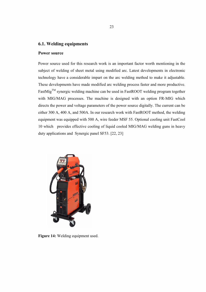
FastMigTM synergic welding machine can be used in FastROOT welding program together
with MIG/MAG processes. The machine is designed with an option FR-MIG which
directs the power and voltage parameters of the power source digitally. The current can be
either 300 A, 400 A, and 500A. In our research work with FastROOT method, the welding
equipment was equipped with 500 A, wire feeder MSF 55. Optional cooling unit FastCool
10 which provides effective cooling of liquid cooled MIG/MAG welding guns in heavy
duty applications and Synergic panel SF53. [22, 23]
Figure 14: Welding equipment used.
24
Shielding gases
The shielding gas forms the arc plasma, stabilizes the arc on the metal being welded, and
shields the arc and molten weld pool so that the chemical and physical reactions are not
affected by atmospheric pollutants. It also affects the transfer mode of the metal. There are
three primary metal transfer modes: Spray transfer, Globular transfer, and Short circuiting
transfer. There are different types of gases that can be used in a particular metal transfer
mode.
The principal gases used are can be inert (argon, helium) or oxidizing (CO2, O2). The
gases used in the GMAW are mixtures of inert gases which may also contain small
quantities of oxygen and CO2. The selection of the best shielding gas is based on the
consideration of the material to be welded and the type of metal transfer that will be used.
In short circuit transfer mode, the mixtures of these gases depend on the type of base
material, the thickness of base material and the characteristic of the weld. [25]
Argon
Most of the gas metal arc welding uses argon as the shielded gas; this is because it gives
no spatter, good arc characteristics, mechanical properties and strength of a weld. Welding
of ferrous and non ferrous metals is obvious with argon, but welding of ferrous metal is
good with a mixture of CO2 or O2.This is because when used pure argon as shielded gas,
there will be lack of transfer of molten metal along the sides of the weld due to relatively
low thermal conductivity of argon gas and hence gives the undercut and porosity.
Short circuit type metal transfer mode can be better achieved with argon as shielded gas
for the welding of sheet metal. Argon creates an excellent current path and gives very
good arc stability due to its low ionization potential. Thin arc column can be produced by
argon at an elevated current density which causes the arc energy to be concentrated in a
small area. This results into deep penetration and good bead shape. Spray transfer mode
can also be achieved with argon as shielded gas. [25, 26]
25
Helium Helium is best used on welding applications that are requiring the improved of bead
wetting, deeper penetration and higher travel speed, this is due of its elevated thermal
conductivity and voltage gradient which results in a broader and more shallow penetration
pattern than argon. Pure helium gas is appropriate for the welding of thick aluminum,
magnesium and copper alloys. The helium arc column is wider than argon which reduces
current density.
It is recommended to mix helium and argon together so as to seize the advantages of the
good quality of both, e.g. helium improves wetting and weld metal coalescence and argon
get better arc stability and cleaning action, in the case of aluminum and magnesiurn.
Helium is a very light gas and therefore tends to disperse into the air after coming out
from the nozzle, therefore restricted flow is needed. It is rarely available in the world
except in Canada, and very much expensive in Europe. [26, 27]
CO2
CO2 is a reactive gas that is mostly used in its pure form in the gas metal arc welding of
carbon and low alloy steel. CO2 is only restricted in globular and short circuiting transfer.
It has a high welding speed, greater joint penetration and good weld shape due to its high
thermal conductivity. It is easily available, has a lower cost and easily installed. In CO2
shielding, the tip of the electrode should be below the surface of the work ` buried arc ´ in
order to minimize spatters. With CO2 welding, very low sound deposits, good mechanical
properties are achieved but may be adversely affected due to the oxidizing nature. The use
of deoxidizers in filler wire is recommended while welding with CO2 to avoid the loss of
some alloying elements. To off-set the performance characteristic of pure CO2 it is often
mixed with Argon. To maximize the impact properties of a metal it is recommended to
mixed CO2 and argon in the following proportion 98/2, 95/5, 82/18, 75/25, 50/50 (figure
15). [24, 26]
26
Figure 15: Comparison of effect of CO2, and mixture of CO2 and Argon. [26]
Process Parameters
Knowledge and control of the process variable is essential so as to produce a weld of
satisfactory quality. These variables are not completely independent of one another,
changing one variable generally requires changing one or more to produce a good quality
weld.
Electrode Size
The base metal thickness changes with the size of the electrode and all these changes have
been proposed in the manual of the welding equipment used. In the manual the thickness
of the base metal size increases so as the electrode size. The proposed electrode wires in
this user manual range from 0.8 to 2.4 mm. Each size depends on the precise arc type
(spray or short circuit) which in turn depends on the acceptable current range. Higher
current produces additional electrode melting, larger penetration and larger more fluid
weld deposit, but may avoid the use of some electrode in the vertical position. The
electrode influences the weld bead pattern. [22, 27]
Amperage The choice of current depends on the electrode size, the mode of transfer of metal and the
thickness of the base metal. In our research work, the current was fluctuating in
27
conventional MAG and synergic pulse welding. But with FastROOT method current and
voltage are synchronized. When the current is low the surface of the weld is rough, and
there is incomplete fusion whereas when the current is high it causes porosity, spatter and
poor bead shape. With the welding equipment used when the wire feed rate is high the
amperage is also high, and low with low amperage. [8, 27]
Arc Voltage The arc voltage has a lot to play in the welding process because it affects the quality of the
weld in several ways. The choice of voltage decides the amperage and the type of metal
transfer. The selection of voltage is based on the thickness of base metal, electrode size,
the joint type, shielding gas composition and the type of weld. With the FastROOT
method voltage and current are synchronized, so a better selection depend on wire feed
speed, FPu and traveling speed to achieve a good quality weld.
Diverse attempt is needed to carry out in order to select an appropriate voltage, because
voltage varies with little difference in almost every parameter so to make good selection,
all other parameters should be defined correctly. Initial value of voltage should be taken
from the user manual of welding equipment, and when the value is too high or too low
above the usage value there will be defeats on the weld like porosity, undercut, spatter and
overlap at the weld edges. [22, 27]
Electrode Extension
Electrode extension is mostly called the wire stick out. It is the distance between the last
point of electrical contact (usually the gun contact or tube) and the end of the electrode.
An increase in the amount of this extension causes an increase in electrical resistance (I2
R). This, in turn, generates additional heat in the electrode, which contributes to a greater
electrode melting rate. When the arc voltage is less, the weld bead will be narrow and
28
high-crowned. The most favorable electrode extension generally ranges from 6 to 13 mm
for short circuiting transfer and dip transfer. [27]
Arc travel speed
The arc travel speed affects the penetration and the weld bead shape. When the other
parameters have been evaluated and fixed, a certain welding speed will give a better
penetration and smooth weld bead. The weld pool is low and larger when the travel speed
is lesser; this is because the arc falls on the weld pool instead on the base metal. The weld
bead is narrow when the penetration is reduced. This is caused by the reduced heat input
which comes as a result of high travel speed. Extreme arc travel speed causes undercutting
because there will not be not adequate amount of weld metal deposits. [27]
Electrode position
The electrode position influences the weld penetration and bead shape to a great extent
larger than arc voltage and arc current. Commonly used welding torch angle for all
position should range from 5 to 150 (from the perpendicular) provides a weld with greatest
penetration and narrow, curved surface arrangement, it provides for maximum shielding of
the molten weld pool. On the other hand, the technique utilizes a leading travel angle,
which provides better visibility for the operator and a weld with flatter surface profile.
[27]
Inductance
Current raise as soon as the electrode shorts to the work. The circuits attribute affecting
the time rate of this increases in current is inductance. For short arc welding, the best
dynamic is usually between two extremes. Right droplet formation is held back when the
inductance is too high, and spatter might result when the inductance is too low. [3]
29
Arc length
Arc length is necessary when the arc regulation utilizes a constant- current power source
and a variable- speed, voltage sensing electrode supplier. With the change in arc length,
consequently there is changed in the voltage across the arc. When this change is made, the
wire feed speed should also be changed so as to provide either more or less electrode per
unit time. This method of regulation is usually limited to larger electrode with lower feed
speed. [8]
FPu This key is only available in Synergic panel SF53 used in the FastROOT method. It
functions to bring energy to the base material, hence penetration to the base material. It is
also called the`` Arc Dynamics Key´´ and it is described by fine tuning of the arc. [22]
Adjustment of the force pulse/arc force influences the welding stability and the spatter
amount. When the setting of force pulse is negative there arc is softer and this reduced
spatters. Positive values of force pulse create a harder arc in favour of increased stability
and when 100% CO2 shielding gas is used in welding of steel. Recommended set value
(0) is a good all-purpose use for regulating the roughness of the arc. [32]
6.2. Welding materials
The following materials were used in our research work;
Structural steel Standard: SFS-EN 10 204/1
Thickness 1.5 mm
Properties [%]; C = 0. 04, Si = 0.010, Mn = 0 .17, P = 0.007, S = 0.011, Al = 0,039
K1 = 10 (K1: transverse rectangular test piece);
Re = 177 N/mm 2 (Re: Yield strength according to the steel standard);
30
Rm = 305 N/mm 2 (Rm: resistance of material according to the steel standard);
Lo = 80 mm.
A = 41 %
To make out if the weldability of this material is free from cold and hot cracking, the
formulas for carbon equivalent and units of crack susceptibility were applied;
Applying the formulae; CE (IIW) = C + Mn/6 + (Cu + Ni)/15 + (Cr + Mo + V)/5,
It was evaluated that CE (IIW) ≈ 0.07 which is less than 0.41. This implies that the
weldability of this material is free from cold cracking.
Applying the formulae; UCS = 230 C + 190 S + 75 P + 45 Nb – 12.3 Si – 5.4 Mn -1, it
was calculated that UCS ≈ 9.8 which is less than 10. Consequently the weldability of this
material is also free from hot cracking.
Stainless steel Grade: 1.4301 type 304
The thickness =1.5 mm
Properties [%]; C = 0. 05, Si = 0.42, Mn = 1.58, P = 0.031, S = 0.003, Cr =18.2, Ni =8.1,
N = 0.059.
Rp0.2 = 341 N/mm 2 (Rp: Yield strength according to the steel standard);
Rm = 627 N/mm 2 (Rm: resistance of material according to the steel standard);
Hardness 173 HB30 (HB 30 Brinell hardness)
Grade: 1.4301 type 349
The thickness = 1.5 mm
Properties [%]; C = 0. 021, Si = 0.44, Mn = 1.60, P = 0.033, S = 0.001, Cr =18.1, Ni = 8.2,
N = 0.045
Rp0.2 = 386 N/mm 2 (Rp: Yield strength according to the steel standard)
31
Rm = 648 N/mm 2 (Rm: Resistance of material according to the steel standard)
Hardness 185 HB30 (HB 30 Brinell hardness)
To recognize if the stainless steel used in our research work is free from cold cracking and
hot cracking, the most convenient ways is to make out the effect of various elements on
the basic structure of chromium-nickel stainless steels is the Schaeffler diagram,
frequently used in welding. It plots the compositional limits at room temperature of
austenite, ferrite and martensite, in terms of nickel and chromium equivalents.
Chromium equivalent (Cr-eq) is calculated using the weight percentage of ferrite
stabilizing elements as follows;
Cr-eq = % Cr +1.5 × % Si + Mo + 0.5% Nb = 20.4
Nickel equivalent (Ni-eq) is calculated using the weight percentage of austenite stabilizing
elements:
Ni-eq = % Ni + 30 × % C +0.5 × % Mn + % Co ≈ 9.63
Identifying if the weldability of the material (stainless steel) is freed from cold and hot
cracking, the values were fitted on the Schaeffler diagram and interpolated; it was found
that the values meet at the region (triangle) of the diagram that is free from defeats such as
cold and hot cracking.
In addition the welding of the material was carried out in ambient temperature of > 00 ; the
welding was also carried out without rust, grease or other foreign substances left over in
grooves or under hot and humid weather conditions; no hydrogen content; lack of boron in
the materials. [12]
32
6.3. Welding experiments
The experiments were carried out under short circuiting welding conditions making use of
a transistorized power source.
The Welding methods used were conventional MAG, Synergic and FastROOT.
The welding materials used were structural steel and stainless steels. The thickness of
materials was 1.5 mm;
The type of joint was corner joint;
The number of pass was one;
The welding direction was vertical downward (welding of sheet metals because the arc
penetrates less due to the travel speed);
The angle of inclination, with respect to the direction of welding was 0 to 100;
The electrode extension was from 6 to 13 mm;
The intensity of welding current in all methods ranges from 84 to 142 A;
The arc voltage also ranges from 12.7 to 20 V;
The rate of welding was from 13 to 20 mm/sec;
The wire feed rate was from 3.3 to 5.5 m/min;
The rate of flow of shielding gas was 15 l/min;
The air gap was from 0 to 1.5 mm with different types of openings;
The test parameters can be referred on appendix 1 to 12;
For structural steel;
The electrode size was 1.0 mm and called OK Autrod 12.50 (SFS-EN 440: G 3 Si1) [26]
The shielding gas composition was Ar +8%CO2+ 0.03%NO, (EN 439-S M21+O, 03 NO)
[28]
For stainless steel;
The electrode size 1.0 mm and called OK Autrod 16.32 (AWS A/SFA 5.9: ER 316 LSi)
[28]
The shielding gas composition was Ar +2%CO2+ 0.03%NO, (EN 439-S M12+0, 03 NO)
[28]
33
7. Welding results and results analysis Before the sheet metals were welded in corner joints there were elimination of lubricants
from the base material which reduced smearing the surface of the material, which could
entrap oxides and impurities under the surface. This is best done with solvents [27]. The
experiment is automatic welding in which clamping of the work piece was done manually
and the welding is done by a robot.
Experiment 1: Synergic pulse welding (MAG-P)
The experiment was carried out with welding equipment Kemppi MIG 4000W and
Kempo MIG Feed. The program used in this experiment was L2; and it gave us the right
diameter of consumable electrode and shielding gas combination for welding of structural
steel of 1.5 mm thickness.
The Pulsed arc technique is characterized by the controlled material transfer. In the ground
current phase, the energy supply is reduced to such an extent that the arc is still only just
stable and the surface of the workpiece is preheated. The main current phase uses a precise
current pulse for targeted droplet detachment. An unwanted short circuit with
simultaneous droplet explosion is ruled out, as is uncontrolled welding spatters. [29]
34
Case 1: Zero air gap
Sheet metal
Welding gun
Figure 16: Show the set–up of welding of zero air gap with MAG-P.
We tested of different parameters to see the desired changes when welding of sheet metal
of zero air gap, with the torch perpendicular to the work piece, and pointing exactly at the
middle of the gap as can be seen from figure 16.
The recommendation from manufacturer of welding equipment shows that when a 1.5 mm
thickness has to be welded, the wire feed speed should be 3.2 m/min and voltage will read
15.7 V. When different parameters were altered as can be seen in appendix 1, it was
realized that when the welding speed is 16 mm/ sec, feeding speed 3.2 m/min, voltage
15.7 V, stick out of 6mm, inductance of zero, and the intensity of the welding current of
ranges from 84 to 121 A, a very good quality weld can be realized as can be seen on the
figure 17.
wel
ding
dire
ctio
n
35
• With low inductance setting the welding was relative cold and this helps the
electrode to freeze in the weld pool
• When the stick out is 6 mm the quality of the weld is good, this setting was
maintained throughout the synergic pulse welding and conventional MAG welding
because the arc burnt very well.
Zero air gap
Figure 17: shows result obtained when welds zero air gap with MAG-P.
36
Case 2: Increasing air gap
Figure 18: Shows the set up of increasing air gap and result obtained with MAG-P. When the parameters were altered as can be seen in appendix 2 with the same set up, it
was realized that a good quality weld can be achieved as can be seen on figure 18. with an
increasing air gap of 0.8 mm with feeding rate of 3.2 m/min, travelling speed of 15
mm/sec, voltage remained 15.7 V, a stick out 6 mm, inductance of 0, and the current of
84…122 A.
When the direction of welding was changed (dragging direction) with the same
parameters, we realised very little changes on the weld.
• When welding sheet metals with air gap of less than 0.8 mm inductance have little
or no effect on the weld puddle when welding of thin plates of little air gap, a
negative inductance have some advantage as smoothness of the weld.
37
Case 3 Air gap in the middle
Figure 19: Show the set of the air gap in the middle with MAG-P and the result obtained. When the air gap was 0.5 to 1.0 mm in the middle of the sheet metal as can be seen on
figure 19 with the gun angle of 900 to the work pieces, we were able to weld up to a
certain air gap. When the parameters were altered with air gap as can be scrutinized in
appendix 3a, it was observed that to realized a good quality weld with an air gap of 0.5
mm in the middle, the travelling speed should be 15 mm/sec, feeding speed should be 3.2
m/min, voltage should be 16 V, stick out should be 6mm, with current ranges from
87…101 A.
• It was realised that as the travelling speed is increasing, the weld pool solidifies
very quickly. Impurities and gases are not permitted to be discharged. The bead is
narrow and the waves pointed. So when the travelling speed is increases the
feeding speed should also be increased so that the weld can have enough weld
puddle.
38
• It was also realized that the electrode angle is of great important when welding of
fillet weld. When making a fillet, the consumable electrode should be held so that
it bisects the angle between the plates and it is perpendicular to the line of the
weld.
When the gun was placed at the tip of one of the work piece as can be seen on the figure
20. It was realized that there was little effect on the bead of the weld; it looks smooth with
a voltage of 13.7 and an inductance of 0, with the other parameters constant. The changes
can be scrutinized in appendix 3b
Figure 20: Shows the set-up and the result of 0.8 mm air gap with MAG-P.
When we changed the air gap to 1mm in the middle, varying welding speed, keeping the
other parameters constant as recommended by producer of machine when welding of 1.5
mm base metal, it was realized that as the welding speed increases there was bad effect of
weld puddle consequently the quality of the weld was not good. The changes and outcome
can be observed in appendix 3c.
39
It was appreciated that when welding with speed of 13 mm/min the quality of the weld
looks better than other welding speed, we decided to keep welding speed constant at 13
mm/min and altering voltage. At voltage of 14 V to 14.6 V it was noticed a weld of good
quality can be achieved .This can be scrutinized in appendix 3d.
When we modified the wire feed speed, maintaining the traveling speed and voltage it was
recognized that when the air gap is reduced to 0.8, it resulted with a good looking weld as
of figure 20 with a welding speed of 13 mm/sec, 15.7 V, and 3.3 m/min.
• When the speed is increasing to about 18 or 20mm/sec, the voltage should be 19.7
V and 20 V the air gap should also be reduced to about 0.6 or 0.5mm respectively,
then the quality of the weld will be very good. When the inductance is change
negatively or positively values, the weld is not smooth, therefore the inductance
should be maintained in zero. This can be scrutinized in appendix 3e.
40
Experiment 2: Conventional MAG welding With conventional MAG welding, the same equipment and accessories were used as in
synergic, and in the control panel the button is changed to MAG.
Case 1: Zero air gap
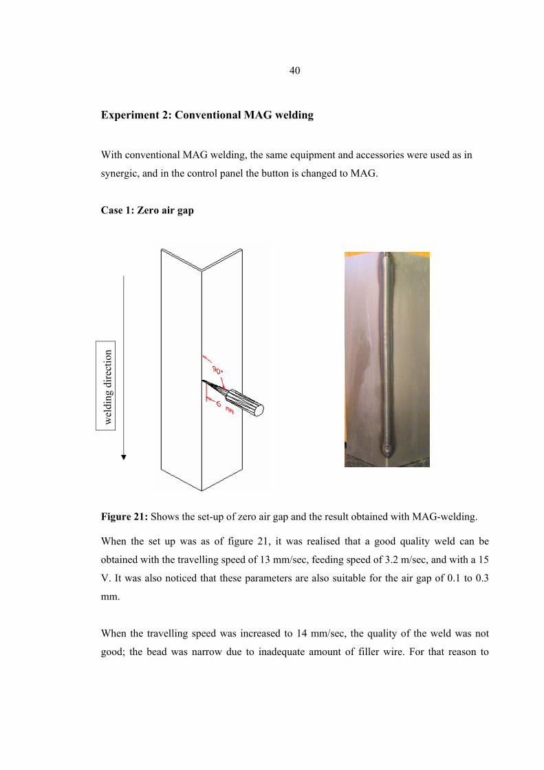
Figure 21: Shows the set-up of zero air gap and the result obtained with MAG-welding. When the set up was as of figure 21, it was realised that a good quality weld can be
obtained with the travelling speed of 13 mm/sec, feeding speed of 3.2 m/sec, and with a 15
V. It was also noticed that these parameters are also suitable for the air gap of 0.1 to 0.3
mm.
When the travelling speed was increased to 14 mm/sec, the quality of the weld was not
good; the bead was narrow due to inadequate amount of filler wire. For that reason to
wel
ding
dire
ctio
n
41
obtain a smooth weld with the speed of 14 mm/sec, the wire feed speed should be
increased. The above explanation can be scrutinized on appendix 4.
Case 2: Increasing air gap
Figure 22: Shows the set-up of the increasing air gap and the result obtained with MAG-
welding.
When welding an increasing air gap of 1mm with the set-up as of figure 22 it was noticed
that it is impossible to weld up to 1 mm because of defects like incomplete fusion. A very
good quality weld can be realised (figure 22) with an increasing air gap of 0.7 mm on the
work piece with an inductance of 0 and travelling speed of 13 mm/sec, the other
parameters stayed the same as proposed by producers of welding equipment when welding
sheet metal of 1.5 mm. The above explanation can be scrutinized on appendix 5.
• The increasing air gap was 1mm and the weld pool filled up to about 5/6 distance
away.
42
Case 3: Air gap in the middle
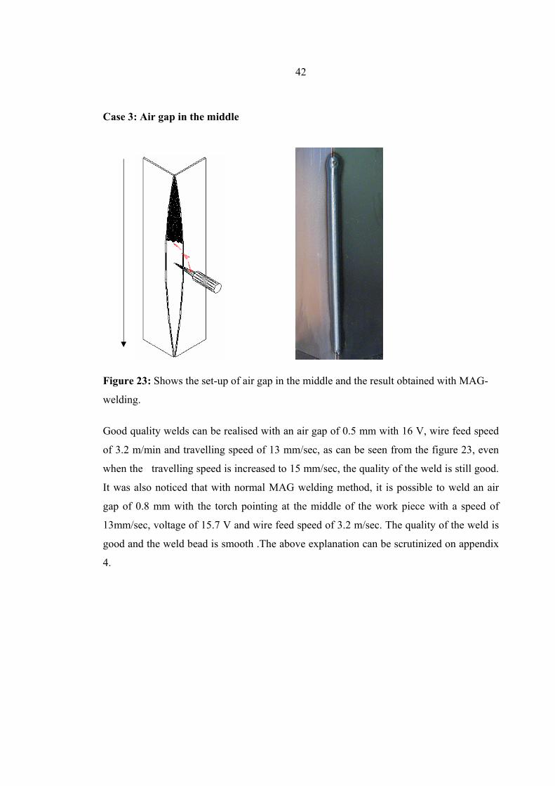
Figure 23: Shows the set-up of air gap in the middle and the result obtained with MAG-
welding.
Good quality welds can be realised with an air gap of 0.5 mm with 16 V, wire feed speed
of 3.2 m/min and travelling speed of 13 mm/sec, as can be seen from the figure 23, even
when the travelling speed is increased to 15 mm/sec, the quality of the weld is still good.
It was also noticed that with normal MAG welding method, it is possible to weld an air
gap of 0.8 mm with the torch pointing at the middle of the work piece with a speed of
13mm/sec, voltage of 15.7 V and wire feed speed of 3.2 m/sec. The quality of the weld is
good and the weld bead is smooth .The above explanation can be scrutinized on appendix
4.
43
Consequence of changes in process variables on weld attributes of Synergic and
Normal MAG methods:
When we make observations or examined the welded pieces obtained with synergic and
conventional MAG-methods with the parameters that were used we came to conclusion
that;
• When the wire feed speed is increased, there is also increased in current. This has
an effect on the penetration, deposition rate, bead size and a slight effect of the
bead width.
• Voltage has a little or no effect to play on the penetration, deposition rate, bead
size and the bead width because voltage decides the amperage and the type of
metal transfer. In order to select an appropriate voltage the thickness of the base
metal, electrode size, the type of joint and the shielding gas composition should be
taken into consideration. There will be defeats if correct voltage is not chosen.
• When traveling speed is increased the penetration is reduced. The bead size, bead
width increases when the traveling speed is reduced, and vice versa. It has very
slight effect on the deposition rate.
• When electrode extension decreases, there is increase in penetration, and when it
increases there is decreased in penetration. The other changes depend on the
changes in current levels with adjustment of wire feed speed.
• When the wire diameter is decreased the penetration increased, and when it is
increased the penetration decreases. The other changes are parallel to the changes
of the wire diameter.
• Gun angle also play an important role when welding sheet metals. It is important to
use push angle because it give good penetration and good visualisation of the weld
puddle.
The above explanations have been summarised in Table 1.
44
Table 1: The effect of changes in process variables on weld attributes of Synergic and
Normal MAG methods:
DESIRED CHANGES WELDING VARIABLE TO
CHANGE Penetration Deposition rate Bead size Bead width Increase Increase Increase Increase Slight effect Current and
wire feed
speed
Decrease Decrease Decrease Decrease Slight effect
Increase Slight effect Slight effect Slight effect Slight effect Voltage
(*)Will result in desired change if current levels are maintained by adjustment of wire feed
speed.
.
45
Experiment 3: FastROOT welding A. Structural steel
The experiment was carried out with the welding equipment Kemppi MSF 55, Fastmig
KMS 500 and Fastcool 10. The program used was 903; it gave us the right diameter of
consumable electrode and shielding gas combination for welding of structural steel of 1.5
mm thickness. In this process the voltage and current are synchronized. The experiment
was carried out with a hot start in FastROOT method.
Case 1: Zero air gap
Figure 24: Set up of the welding of zero air gap and the result obtained with FastROOT
method with structural steel.
When sheet metals were welded with no air gap with this method, it was realised that
when the stick-out is less than 10 mm the arc is burning out of the work piece, it burnt
underneath the workpiece. To obtain a nice looking weld, the stick out should be 13 mm.
When welded with torch angle perpendicular to workpiece the quality of the weld is not as
good as compared to when the angle of the torch was changed to 970 vertically on the
workpiece. It was also noted that when the FPu is zero, the weld looks much better than
when used negative FPu. With a negative arc length and zero FPU there was little
46
significance on the quality of the weld. When the arc length was positive, there were no
great changes in the superiority of the weld. When the parameters were altered it was
found that to realise a very good quality weld with this type of air gap the parameters
should be fixed at the travelling speed of 13 mm/sec, wire feed rate of 3.5 m/min, voltage
of about 15 V, arc length should read 15, current should be about 95 A, and FPu should be
fixed at 0. All these investigations can be scrutinized as of appendix 6.
• It was also realized that when we kept all the parameters constant and changed the
position of torch to the tip of one of the sheet metals (workpiece), the weld was of
good quality.
• The role of the Arc length is to adjust the heat input and it is a function of the
opening of the air gap and the stick out length.
Case 2: Increasing air gap
Figure 25: Shows set-up of the increasing air gap of FastROOT method with structural
steel.
When welding increasing air gap of this method and with the same parameters as in case
1.ie (Traveling speed of 13 mm/sec, wire feed rate of 3.7 mm/min, voltage of about 16.5
V, arc length of 15, current of about 98 A , and FPu of -20.) but with an increase in wire
feed rate, we were able to weld a very good quality air gap of 1.2 mm with the filler wire
47
pointing at the tip of one of the workpiece as can be seen on the 2nd figure 25. When the
FPU is -20 the arc is burning with a spreading manner and this helps the weld puddle to
spread in a large area enabling the gap to be filled. When the angle of the torch was
perpendicular to the work piece as can be seen on the 3rd figure 25 it was observed that the
weld was having a hole mid way to the end.
Once more; when the angle was about 920 to 940 vertically from the work piece and the
direction of welding was push or drag it was realized that the weld was not of good quality
as compared to when the angle of the torch was increased to 970. It was also realized that
when the traveling speed is 13mm/sec and feeding speed is 16.5 m/min, the quality of the
weld is very good with an air gap of 0.8 mm. The outcome of the welding with an air gap
of 1.2 mm can be seen on figure 26. These investigations can be scrutinized in appendix 7.
When the FPU is increased to zero and the stick-out is from 13 to 15 mm, the quality of
the weld is better. In this method when the stick out is about 13 or 14 mm the arc burnt in
a larger area on the work piece. This entails that the arc should burn in front of the weld
puddle, to ensure nice looking weld;
• The advantage of this method (FastROOT) over the others methods is that the arc
burns very well even though feeding speed is increased, in other cases the arc will
be skipped from one place to another.
• In this method, the wire feed speed should be correctly chosen so as to have a
smooth weld because as wire feed speed increases so as voltage and current.
• It was also noticed that when the gun is placed at the middle of the workpiece it is
possible to weld air gap of up to 1.2 mm and it experiences less voltage.
48
Increasing air gap of 1.2
Figure 26: Result obtained with increasing air gap of 1.2 mm with FastROOT method
with structural steel.
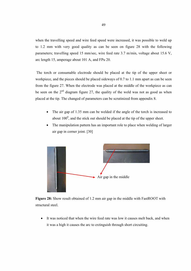
Case 3: Air gap in the middle Figure 27: Set-up of air gap in the middle with structural steel with FastROOT When an air gap of 1.5 mm in the middle was weld it was realised that it was impossible
to weld up to that wide while reducing and trying different parameters, we found out that
49
when the travelling speed and wire feed speed were increased, it was possible to weld up
to 1.2 mm with very good quality as can be seen on figure 28 with the following
parameters; travelling speed 15 mm/sec, wire feed rate 3.7 m/min, voltage about 15.6 V,
arc length 15, amperage about 101 A, and FPu 20.
The torch or consumable electrode should be placed at the tip of the upper sheet or
workpiece, and the pieces should be placed sideways of 0.7 to 1.1 mm apart as can be seen
from the figure 27. When the electrode was placed at the middle of the workpiece as can
be seen on the 2nd diagram figure 27, the quality of the weld was not as good as when
placed at the tip. The changed of parameters can be scrutinized from appendix 8.
• The air gap of 1.35 mm can be welded if the angle of the torch is increased to
about 1000, and the stick out should be placed at the tip of the upper sheet.
• The manipulation pattern has an important role to place when welding of larger
air gap in corner joint. [30]
Air gap in the middle Figure 28: Show result obtained of 1.2 mm air gap in the middle with FastROOT with
structural steel.
• It was noticed that when the wire feed rate was low it causes melt back, and when
it was a high it causes the arc to extinguish through short circuiting.
50
B. Stainless steel Research on stainless steel sheet was with FastROOT method only; Case 1: Zero air gap
Figure 29: Show the set up of zero air gap and result obtained with FastROOT method
with stainless steel.
With FastROOT method it was realized that when traveling and feeding speeds were
increased to 19 mm/sec and 3.5 m/min respectively to reach zero air gap a good quality
weld can be achieved as of figure 29. The arc length was maintained to 20 and the FPu can
be 0 or 20. The angle of the torch was fixed at 970 and the torch was positioned in the
middle of the workpiece. When the traveling speed is increased the feeding speed should
also be increased so that the weld puddle will be sufficient to create a smooth weld. The
above explanations can be scrutinized on appendix 9.
• With FastROOT process a very high welding speed can be achieved because the
welding process checks the dip transfer and correct the times of the separation of
the weld bead from the wire into the weld pool. [31]
51
• The fast processing speed result in a minimal heat affected zone which lead to
little workpieces distortion.
Case 2: Air gap in the middle Figure 30: Show the set up of air gap in the middle with FastROOT method with stainless
steel.
With FastROOT method it was realized that an air gap of up to 1.35 mm with stainless
steel as the base metal can be welded if one sheet is placed above the other of about 0.7 to
1.1 mm away from the tip of the other sheet as can be seen from figure 30, and the torch
or electrode should point to the tip of the upper sheet. A very good quality weld with an
air gap of 1.35 mm can be produced as of figure 31 with welding with wire feed speed of
17 mm/sec and 3.8 m/min respectively. The arc length and FPU kept at 20 and 20
respectively.
But when the parameters were maintained and gun (filler wire) at the middle of the work
piece, it was realized that we were able to weld only 0.8 mm air gap. The above
explanations can be scrutinized on appendix 10 and 11.
52
Air gap in the middle
Figure 31: Weld obtained of air gap in the middle with FastROOT method with stainless
steel.
• It was also noticed that while the arc length was 40 and FPU 20, the arc spread in a
larger area, it helps the weld puddle to solidify in a larger area and this makes the
weld bead smoother.
• The cooling rate, and density of stainless steel is high compared to structural
steel, that is why it is possible to weld up to 1.35 mm air gap
• Heat conductivity and fluidity of stainless steel is high as compared to structural
steel.
• It was noticed that an increase in voltage makes the weld narrower.
53
Practical container The practical boxes were expected to be welded using the appropriate parameters from
FastROOT welding;
Firstly, the box was clamped on a table, and a cord was fixed firmly round the box so that
the joints can be in position before doing the tack welding. Tack welding was done at two
positions at the line of the joints. Different manipulation pattern of air gaps of the joint
were prepared at different corners so as to see the effect on the weld.
After the tack welding has been done, the cord is uptight from the boxes which are now
ready to be welded. The air gaps are then measured in different positions so as to choose
the right welding parameters. The air gaps of fusion line (corners) are quite different in
dimensions, they ranges from 0 to 0.5 mm. When the air-gaps have been measured in
different positions, the choice of parameters will be taken into consideration the largest air
gap on that joint line.
The set up of the gun was fixed at 970 to the workpiece. The stick out was maintained to
13 mm away throughout the welding of the boxes.
The gun or stick-out was first placed at the tip of one of the sheet metal or workpiece.
When the weld was done with suitable parameters for the largest air gap of about 0.5 mm;
with traveling speed of 20 mm/sec, wire feed rate of 3.5 m/min, arc length of 40 and FPu
of -20 it was realized that a good quality weld can be achieved but with little bulkiness of
bead at the position where the tack weld was done. Oxidation will occur at the position of
tack weld which causes porosity. It should be noted that with FastROOT method current
and voltage are synchronized.
• It is wise to make tack weld at the extreme corner of the sheet metals.
At the other joint line, tack weld was done at the edge of the workpiece and the other
parameters were kept constant. It was also noticed that a very smooth weld with no defeats
can be achieved with a traveling speed of 20 mm/sec as of figure 32. This can be
scrutinized on appendix 11.
54
Figure 32: Shows container that has been welded using FastROOT method.
• It was noticed with the above parameter it is possible to weld good quality weld
with air gaps which ranges from 0 to 0.7 mm.
• It was also noticed that highest speed is attained with FastROOT method with no
cracking.
When the gun is placed at the middle of the workpiece it was noticed that to attain a good
quality weld the welding speed should reduced to 17mm/sec with all other parameters
constant (wire feed speed of 3.5 m/min, arc length 40, FPu -20). This explanation can be
scrutinized in appendix 12.
• It was noticed that a smooth weld is achieved with this type of placement of gun
(in the middle of workpiece) with air gap from 0 to 0.3 mm.
• It was also noticed that with a traveling speed of 17 to 20 mm/sec for air gaps of 0
to 0.3 mm the current is reduced with wire feed speed of 3.5 m/min, arc length of
40 and FPu of -20.
We also tested of vertical gun angle of 400 to the workpiece, it was observed that a good
weld can also be achieved with this placement with the same parameters as above.
As of figure 32, one can draw conclusion that the parameters that were used, were
reasonably appropriate for the welding of sheet metals of 1.5 mm.
• FastROOT method is first-rated because of the high traveling speed with very little
or no defeat on the base metal.
55
8. Conclusion In our research work we noticed that modified short arc welding method (FastROOT)
possesses so many advantages as compared to conventional and synergic methods because
of;
• FastROOT method possesses less heat input (0.082 kJ/mm) of about 25% lower
than normal MAG method on the weld-piece and as a result less effect on the
metallurgic properties of the welded material.
• The ability to control the transfer of metal and therefore better control on the weld
puddle.
• It was also noticed that with FastROOT method the stick-out should be about 12 to
14 mm; consequently the arc will burn appropriately on the workpiece.
• The angle of the gun has an important role on the quality of the weld with
FastROOT method so the angle of the gun should be placed at 50 to 150 vertically
to the workpiece.
• The ability to weld air gap up to 1.35 mm with faster speeds of 18 to 20 mm/sec
with stainless steel with FastROOT method. This is due to the control of metal
transfer to the weld; and also the cooling rate, density, heat conductivity and
fluidity of stainless steel is high as compared to structural steel. But it is also
impossible to weld air gap of more than 1 mm with other MAG methods with
welding speed of more than 15 mm/sec.
• It was also noticed that the manipulation pattern of air gap has a great deal to play
when welding sheet metal in corner joint with air gap greater than 0.5 mm when
using modified short arc welding.
• It was observed that when the gun (stick-out) was placed at the tip of one of the
work piece the quality of the weld is good as compared when placed at the middle
of the workpieces.
• It was noticed with FastROOT method that, when the wire feed rate was low it
causes melt back, and when it was high it causes the arc to extinguish through
short circuiting
56
• The bead on the welded piece look quite smooth with structural and stainless steel
with modified short arc method, and there were absence of defeats such as overlap,
lack of fusion, lack of penetration, porosity and crack.
• When the weld is observed visually one can perceived that the area affected by
heat is rather smaller with modified short arc welding method.
• Modified short arc welding possesses higher-quality welded joints, lower cost for
rejects and post-weld machining, freedom from spatters and the ability to weld
light-gauge sheet.
• The cooling rate has a great deal to play on the metallurgy properties of the welded
material and it is high with FastROOT method as compared to synergic pulse
method and conventional MAG method due to the low heat input of about 25%
lower than normal MAG and about 14 % lesser than synergic pulse method.
57
9. Further Research The research on welding of sheet metal using modified short arc MIG/MAG welding
process was very much encouraging. The parameters got for the different methods with
the manipulations patterns of air gap were also quite interesting.
The call for, is to carry out research on this productive welding process (FastROOT), and
to find out the result when welding;
• MIG-brazing using FastROOT. MIG -brazing is used e.g. in welding galvanized
sheet metals.
• Ultra high strength steels (up to Rp02=1000 N/mm2) using FastROOT, emphasis
should be laid on the mechanical properties in weld and the HAZ. Evaluations
should also be made to witness if this method possesses lower heat input than
normal MAG method.
• Structural steel as base metal and stainless wire as consumable electrode,
emphasize should be laid on different manipulation pattern of workpieces and
orientation of gun both vertically and horizontally.
58
10. Summary The aim of this our research work was to investigate if FastROOT welding method has
high productivity than conventional welding and synergic pulse welding when welding
sheet metals( structural and stainless steels) in corner joint in a single pass with different
air gap. Kemppi power sources were employed in this research work.
Firstly, we started by defining the process principle of Normal MIG/MAG, then the
different new welding processes that are concerned with modified short are MIG/MAG
methods ( FastROOT was among those ).
Next, the experiment part was carried out with different exploitation pattern of air gaps;
zero air gap, increasing air gap and air gap in the middle with different welding method.
Welding parameters were altered and the outcomes were noted with different methods
with different patterns of air gap.
When calculations of heat input was done with the different techniques with all welding
parameters constant, it was realized that FastROOT method produces the lowest thermal
input due to the control of metal transfer at the welding point. Even when view with the
naked eye one can observe that FastROOT method possesses less HAZ on the weld-joints.
It was observed that with modified short arc welding (FastROOT welding) there is
freedom of spatters on the material It produces high quality welded joints with no
cracking.
For the most part, the FastROOT process possesses very fast welding speed consequently
less heat input on the welded joint and as a result less effect on the metallurgic properties
of the welded material. This high processing speed has very good repeatability of welding
result.
Welding sheet metal often means a constant battle between productivity and equipment
investment vs. burn-through, warping, excessive heat affected zones (HAZ) and weld
appearance. For the individual occasionally welding sheet metal, success can be as simple
as learning the proper techniques as with FastROOT method.
59
References [1] MIG welding for improved productivity, Presented at EUROJOIN4-4th European
conference on welding, cutting and joining, Development of welding and allied processes
at the beginning of the new millennium. Cavat Dubrovnik, Croatia, 24-26 May 2001,
pp313-318 [ISBN 953-96454-0-9]
[2] Fronius. Tran Plus Synergic 3200 CMT;
www.fronius.com/welding.technology/products/; Webpage retrieved on Nov 07, 2006.
20 4.5 15.8 40 94 -20 13 0.5 97 Good weld but height of bead higher as compare to above
20 4.5 15.7 40 94 -20 13 1.2 97 good but two holes
20 5 15.7 40 112 -20 13 1.25 97 Fill gap, good quality. chosen as best .F6
20 5.5 16.6 40 120 -20 13 1.25 97 similar
20 5.5 15.9 40 142 -20 13 1.2 97 Fill gap, arc is spreading well, width of weld is large a bit compare to others.
20 5 15.8 40 110 -20 13 1.6 97 holes , we cannot weld air gap of 1.6 with side placement
Appendix 12 Stainless steel and stainless wire
Welding Speed (mm/sec)
Feeding Speed (m/min )
V Arc length
A FPU stick –out (mm)
Air gap (mm)
torch angle (0)
outcome
17 3.5 15.3 40 80 -20 13 0.25 97 smooth, nice appearing weld surface welding of box, side allocation A
17 3.5 15.5 40 80 -20 13 0.3 97 Good weld
17 3.2 15 40 75 -20 13 0.3 97 Excellent weld as compare to the above
71
17 3.2 15.2 40 77 -20 13 1 97 holes in the weld because feeding speed was low, a feeding speed of about 3.7m/min is better for the air gap of 1mm when traveling speed is 17mm/sec.