1 UNIT II WELDING Welding • Welding is a process of joining similar metals by application of heat with or without application of pressure and addition of filler material Weldability • The term “weldability” has been defined as the capacity of being welded into inseparable joints having specified properties such as definite weld strength, proper structure, etc. Factors affecting Weldability 1. Melting Point 2. Thermal conductivity 3. Thermal Expansion 4. Surface condition 5. Change in Microstructure Types of welding 1.Plastic Welding • In Plastic welding or pressure welding, the pieces of metal to be joined are heated to plastic state and then forced together by external pressure. 2. Fusion Welding • In fusion welding or non pressure welding , the material at the joint is heated to molten state and allowed to solidify. Welding Processes 1. Gas welding i. Oxyacetylene ii. Air-acetylene iii. Oxy-hydrogen 2. Arc Welding i. Carbon Arc ii. Metal Arc iii. Gas Metal Arc ( MIG) iv. Gas Tungsten Arc ( TIG) v. Atomic-hydrogen arc vi. Plasma Arc vii. Submerged Arc welding
Transcript
1
UNIT II
WELDING
Welding
• Welding is a process of joining similar metals by application of heat with or
without application of pressure and addition of filler material
Weldability
• The term “weldability” has been defined as the capacity of being welded
into inseparable joints having specified properties such as definite weld
strength, proper structure, etc.
Factors affecting Weldability
1. Melting Point
2. Thermal conductivity
3. Thermal Expansion
4. Surface condition
5. Change in Microstructure
Types of welding
1.Plastic Welding
• In Plastic welding or pressure welding, the pieces of metal to be joined are
heated to plastic state and then forced together by external pressure.
2. Fusion Welding
• In fusion welding or non pressure welding , the material at the joint is heated
to molten state and allowed to solidify.
Welding Processes
1. Gas welding
i. Oxyacetylene
ii. Air-acetylene
iii. Oxy-hydrogen
2. Arc Welding
i. Carbon Arc
ii. Metal Arc
iii. Gas Metal Arc ( MIG)
iv. Gas Tungsten Arc ( TIG)
v. Atomic-hydrogen arc
vi. Plasma Arc
vii. Submerged Arc welding
2
viii. Flux-cored arc
ix. Electro-slag
3. Resistance welding
i. Butt welding
ii. Spot welding
iii. Seam welding
iv. Projection welding
v. Percussion welding
4. Thermit welding
5. Solid State welding
i. Friction
ii. Ultrasonic
iii. Diffusion
iv. Explosive
6. Newer Welding Processes
i. Electron Beam
ii. Laser
7. Related processes
i. Oxyacetylene cutting
ii. Arc cutting
iii. Hard facing
iv. Brazing
v. Soldering
Oxy-Acetylene Welding
max temperature reached: 3300
3
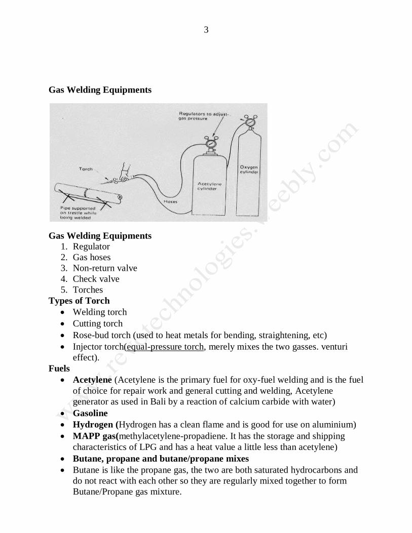
Gas Welding Equipments
Gas Welding Equipments
1. Regulator
2. Gas hoses
3. Non-return valve
4. Check valve
5. Torches
Types of Torch
Welding torch
Cutting torch
Rose-bud torch (used to heat metals for bending, straightening, etc)
Injector torch(equal-pressure torch, merely mixes the two gasses. venturi
effect).
Fuels
Acetylene (Acetylene is the primary fuel for oxy-fuel welding and is the fuel
of choice for repair work and general cutting and welding, Acetylene
generator as used in Bali by a reaction of calcium carbide with water)
Gasoline
Hydrogen (Hydrogen has a clean flame and is good for use on aluminium)
MAPP gas(methylacetylene-propadiene. It has the storage and shipping
characteristics of LPG and has a heat value a little less than acetylene)
Butane, propane and butane/propane mixes
Butane is like the propane gas, the two are both saturated hydrocarbons and
do not react with each other so they are regularly mixed together to form
Butane/Propane gas mixture.
4
Propane does not burn as hot as acetylene in its inner cone, and so it is rarely
used for welding
Propane is cheaper than acetylene and easier to transport.
Propylene(Propylene is used in production welding and cutting. It cuts
similarly to propane. When propylene is used, the torch rarely needs tip
cleaning.
Arc Welding
temperature is 6000 to 7000’c
Comparison of AC and DC Arc Welding
Particulars Direct Current Alternating Current
No-load voltage Low ( higher safety) Too high, over 70V
(Danger)
Efficiency low High (advantageous)
Prime cost High 2 to 3 times of AC low
Connected load normal High ( disadvantage)
Electrodes Both bare (non-coated)
cheaper electrode can be
used
Only coated electrodes i.e.
expensive electrodes can be
used
Welding of non-ferrous suitable Not suitable
5
metals
Heat generation High in +ve pole and low
in –ve pole
Same at each pole
Electrode
• In arc welding an electrode is used to conduct current through a work piece
to fuse two pieces together. Depending upon the process, the electrode is
either consumable, in the case of gas metal arc welding or shielded metal arc
welding, or non-consumable, such as in gas tungsten arc welding.
Coating and Specification
Electrode Types
E6010 This electrode is used for all position welding using DCRP. It
produces a deep penetrating weld and works well on dirty,rusted, or painted
metals
E6011 This electrode has the same characteristics of the E6010, but can be
used with AC and DC currents.
6
E6013 This electrode can be used with AC and DC currents. It produces a
medium penetrating weld with a superior weld bead appearance.
E7018 This electrode is known as a low hydrogen electrode and can be used
with AC or DC. The coating on the electrode has a low moisture content that
reduces the introduction of hydrogen into the weld. The electrode can
produce welds of x-ray quality with medium penetration. (Note, this
electrode must be kept dry. If it gets wet, it must be dried in a rod oven
before use.)
Purpose of Coated Electrodes
1. To facilitate the establishment and maintenance of the arc.
2. To protect the molten metal from the Oxygen and nitrogen of the air
3. To protect the welding seam from rapid cooling
4. To provide the means of introducing alloying elements not contained in the
core wire.
Precautions in Arc Welding
1. Because of the intensity of heat and light rays from the electric arc, the
operator’s hand face and eyes are to be protected while arc is in use
2. Heavy gloves are worn
3. Hand shield or a helmet with window of coloured glass should be used to
protect the face
4. The space for the electric arc welding should be screened off from the rest of
the building to safeguard other workmen from the glare of the arc.
Resistance welding
1. Resistance welding is a process used to join metallic parts with electric
current. There are several forms of resistance welding, including spot
welding, seam welding, projection welding, and butt welding.
2. The heat generated is expressed by the equation
i. E = I2·R·t
where E is the heat energy, I is the current, R is the electrical resistance and t is
the time that the current is applied.
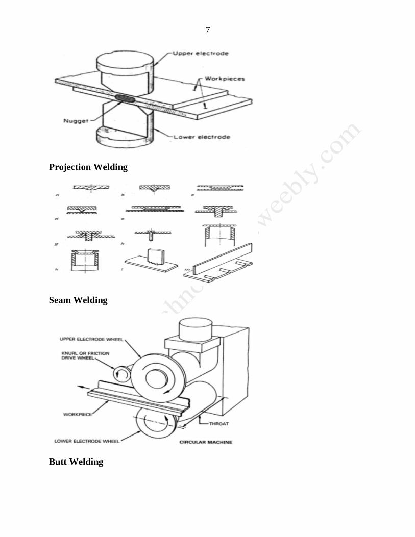
Spot Welding
7
Projection Welding
Seam Welding
Butt Welding
8
Percussion Welding
• Percussion Welding uses electrical energy stored in a condenser to produce
an intense momentary power discharge to provide the localized heating at
the interface. It is suitable for joining dissimilar metals that are not weldable
by flash butt welding, or when flash is not desirable at the weld joint.
Process steps in Percussion Welding
1. The two materials to be welded are positioned with a preset air gap between
them
2. A burst of RF energy ionizes the air gap.
3. Capacitor banks discharge, creating an arc that heats the two materials to a
weldable temperature.
4. When the materials reach the proper welding state, electromagnetic actuators
accelerate them together. The molten masses combine, metal to metal, and
are forged together. As the weld cools, a complete alloy bond is formed.
MIG welding
Gas Metal Arc Welding (GMAW) is frequently referred to as MIG welding. MIG
welding is a commonly used high deposition rate welding process. Wire is
continuously fed from a spool. MIG welding is therefore referred to as a
semiautomatic welding process
MIG Welding Benefits
1. All position capability
9
2. Higher deposition rates than SMAW
3. Less operator skill required
4. Long welds can be made without starts and stops
5. Minimal post weld cleaning is required
Shielding Gases
Argon
Argon - 1 to 5% Oxygen
Argon - 3 to 25% CO2
Argon/Helium
CO2 is also used in its pure form in some MIG welding processes. However,
in some applications the presence of CO2 in the shielding gas may adversely
affect the mechanical properties of the weld.
TIG Welding
TIG Welding
Gas Tungsten Arc Welding (GTAW) is frequently referred to as TIG
welding.
TIG welding is a commonly used high quality welding process.
TIG welding has become a popular choice of welding processes when high
quality, precision welding is required.
In TIG welding an arc is formed between a non consumable tungsten
electrode and the metal being welded.
Gas is fed through the torch to shield the electrode and molten weld pool.
If filler wire is used, it is added to the weld pool separately.
10
TIG Welding
TIG welding
TIG Welding Benefits
Superior quality welds
Welds can be made with or without filler metal
Precise control of welding variables (heat)
Free of spatter
Low distortion
Shielding Gases
Argon
11
Argon + Hydrogen
Argon/Helium
Helium is generally added to increase heat input (increase welding speed or
weld penetration). Hydrogen will result in cleaner looking welds and also
increase heat input, however, Hydrogen may promote porosity or hydrogen
cracking.
TIG Welding Limitations
Requires greater welder dexterity than MIG or stick welding
Lower deposition rates
More costly for welding thick sections
Special Welding Processes
Submerged Arc Welding
Plasma Arc Welding
Thermit Welding
Electron Beam Welding
Friction Welding
Diffusion Welding
Submerged Arc Welding
Submerged arc welding (SAW) is a common arc welding process. It requires
a continuously fed consumable solid or tubular (flux cored) electrode.
The molten weld and the arc zone are protected from atmospheric
contamination by being “submerged” under a blanket of granular fusible
flux consisting of lime, silica, manganese oxide, calcium fluoride, and other
compounds.
When molten, the flux becomes conductive, and provides a current path
between the electrode and the work. This thick layer of flux completely
covers the molten metal thus preventing spatter and sparks as well as
suppressing the intense ultraviolet radiation and fumes that are a part of the
SMAW (shielded metal arc welding) process.
12
SAW
Equipment Used
Power supply
Start plate
Copper mold
Electrode
Guide tube
Wire feed
Power source
SAW head
Flux handling
Protective equipment
Advantages
High deposition rates (over 100 lb/h (45 kg/h) have been reported).
High operating factors in mechanized applications.
Deep weld penetration.
Sound welds are readily made (with good process design and control).
High speed welding of thin sheet steels up to 5 m/min (16 ft/min) is
possible.
Minimal welding fume or arc light is emitted.
Practically no edge preparation is necessary.
The process is suitable for both indoor and outdoor works.
Distortion is much less.
Welds produced are sound, uniform, ductile, corrosion resistant and have
good impact value.
Single pass welds can be made in thick plates with normal equipment.
The arc is always covered under a blanket of flux, thus there is no chance of
spatter of weld.
50% to 90% of the flux is recoverable
13
Limitations
Limited to ferrous (steel or stainless steels) and some nickel based alloys.
Normally limited to the 1F, 1G, and 2F positions.
Normally limited to long straight seams or rotated pipes or vessels.
Sucker Rod * Gear Hub * Cluster Gear * Rock Drill Piston Blank * Valve
Body * Eccentric Shaft *
20
Diffusion welding • The machine is used for diffusion welding process.
• It is a solid state welding process that creates fusion of surfaces to be joined
by applying pressure at high temperatures.
• The welding process may or may not use filler material. If used, they may be
in the form of electroplated surfaces.
• These welders are ideal for joining refractory metals and many other
dissimilar metals.
Diffusion Welding Process
• Diffusion welding process is does not comprise microscopic deformation
melting or relative motion of the parts.
• Heat required for melting the parts is commonly obtained by resistance,
induction or furnace.
• Atmosphere and vacuum furnaces are used for welding general metals. But
for joining most refractory metals, a protective inert atmosphere is used.
Laser beam welding • Laser beam welding (LBW) is a welding technique used to join multiple
pieces of metal through the use of a laser.
• The beam provides a concentrated heat source, allowing for narrow, deep
welds and high welding rates.
• The process is frequently used in high volume applications, such as in the
automotive industry.
•
• Laser welding is a high energy beam process and in this regard is similar to
electron beam.
• With that exception they are unlike one another. The energy density of the
laser is achieved by the concentration of light waves not electrons.
• The laser output is not electrical, does not require electrical continuity, is not
influenced by magnetism, is not limited to electrically conductive materials
and in fact can interact with any material whether it be metal, plastic, wood,
ceramic, etc.
• Finally its function does not require a vacuum nor are x-rays produced.
21
Laser Welding Process
(1) Laser beam welding (LBW) is a welding process which produces coalescence of materials with the heat obtained from the application of a concentrate coherent light beam impinging upon the surfaces to be joined.
(2) The focused laser beam has the highest energy concentration of any known source of
energy. The laser beam is a source of electromagnetic energy or light that can be pro jetted without diverging and can be concentrated to a precise spot. The beam is coherent and of a single frequency.
(3) Gases can emit coherent radiation when contained in an optical resonant cavity. Gas lasers can be operated continuously but originally only at low levels of power. Later
developments allowed the gases in the laser to be cooled so that it could be operated
22
continuously at higher power outputs. The gas lasers are pumped by high radio frequency generators which raise the gas atoms to sufficiently high energy level to cause lasing. Currently, 2000-watt carbon dioxide laser systems are in use. Higher powered systems are
also being used for experimental and developmental work. A 6-kw laser is being used for automotive welding applications and a 10-kw laser has been built for research purposes. There are other types of lasers; however, the continuous carbon dioxide laser now available with 100 watts to 10 kw of power seems the most promising for metalworking applications.
(4) The coherent light emitted by the laser can be focused and reflected in the same way as a light beam. The focused spot size is controlled by a choice of lenses and the distance from it to the base metal. The spot can be made as small as 0.003 in. (0.076 mm) to large areas 10 times as big. A sharply focused spot is used for welding and for cutting. The large spot is used for heat treating.
(5) The laser offers a source of concentrated energy for welding; however, there are only a few lasers in actual production use today. The high-powered laser is extremely expensive.
Laser welding technology is still in its infancy so there will be improvements and the cost of equipment will be reduced. Recent use of fiber optic techniques to carry the laser beam to the point of welding may greatly expand the use of lasers in metal-working.
Applications
There are almost unlimited applications for marking, engraving, cutting, and welding in a substantial amount of companies and industries. Below are just a few of these applications. Please contact us and we would be most happy to process one of your samples that you think has merit at no charge to you.
Electro slag welding (ESW) 1. Electro slag welding (ESW) is a highly productive, single pass welding process for thick
(greater than 25mm up to about 300mm) materials in a vertical or close to vertical
position.
2. (ESW) is similar to electro gas welding, but the main difference is the arc starts in a
different location.
3. An electric arc is initially struck by wire that is fed into the desired weld location and
then flux is added.
4. Additional flux is added until the molten slag, reaching the tip of the electrode,
extinguishes the arc.
5. The wire is then continually fed through a consumable guide tube (can oscillate if
desired) into the surfaces of the metal work pieces and the filler metal are then melted
using the electrical resistance of the molten slag to cause coalescence.
6. The wire and tube then move up along the work piece while a copper retaining shoe that
was put into place before starting (can be water cooled if desired) is used to keep the
weld between the plates that are being welded.
7. Electro slag welding is used mainly to join low carbon steel plates and/or sections that are
very thick.
8. It can also be used on structural steel if certain precautions are observed.
23
9. This process uses a direct current (DC) voltage usually ranging from about 600A and 40-
50V, higher currents are needed for thicker materials. Because the arc is extinguished,
this is not an arc process.
Flux Core Welding
1. FCAW, Flux Core Flux-cored, tubular electrode welding has evolved from the MIG welding process to improve arc action, metal transfer, weld metal properties, and weld appearance.
2. It is an arc welding process in which the heat for welding is provided by an arc between a continuously fed tubular electrode wire and the work piece.
3. Shielding is obtained by a flux contained within the tubular electrode wire or by the flux and an externally supplied shielding gas. A diagram of the process is shown in figure
24
4. FCAW, Flux Core Flux-cored arc welding is similar to gas metal arc welding in many ways.
5. The flux-cored wire used for this process gives it different characteristics.
6. Flux-cored arc welding is widely used for welding ferrous metals and is particularly good for applications in which high deposition rates are needed.
7. At high welding currents, the arc is smooth and more manageable when compared in using large diameter gas metal arc welding electrodes with carbon dioxide.
8. The arc and weld pool are clearly visible to the welder. A slag coating is left on the surface of the weld bead, which must be removed.
9. Since the filler metal transfers across the arc, some spatter is created and some
smoke produced.
Soldering is defined as "the joining of metals by a fusion of alloys which have relatively lw melting points". In other words, you use a metal that has a low melting point to adhere the surfaces to be soldered together. Soldering is more like gluing with molten metal than anything else. Soldering is also a must have skill for all sorts of electrical and electronics work. It is also a skill that must be taught correctly and developed with practice.