Well Casing Cathodic Protection - Design Issues, Lessons Learned and a Case History Jeffrey L. Didas Matcor, Inc. 101 Liberty Lane Chalfont, PA 19111 USA WRGC – Western Regional Gas Conference 2018 Henderson, NV USA
Transcript
Well Casing Cathodic Protection -Design Issues, Lessons Learned
and a Case History
Jeffrey L. DidasMatcor, Inc.
101 Liberty LaneChalfont, PA 19111
USA
WRGC – Western Regional Gas Conference 2018Henderson, NV USA
Overview
• Introduction
• Discussion
• Design Issues
• Case History
• Lessons Learned
• Conclusions
• Wrap Up & Questions
Introduction
The use of cathodic protection – CP for protecting the external steel surfaces of well casings is a proven technique to reduce or minimize external corrosion. Production wells and storage wells utilize cathodic protection and it is quite successful in stopping or minimizing external corrosion. The need for CP on well casings does depend on many factors, primarily economics, corrosive electrolyte in contact with the casing, corrosion cells - long line and localized and stray current interference. The goal of installing CP for well casings is to prevent casing leaks.
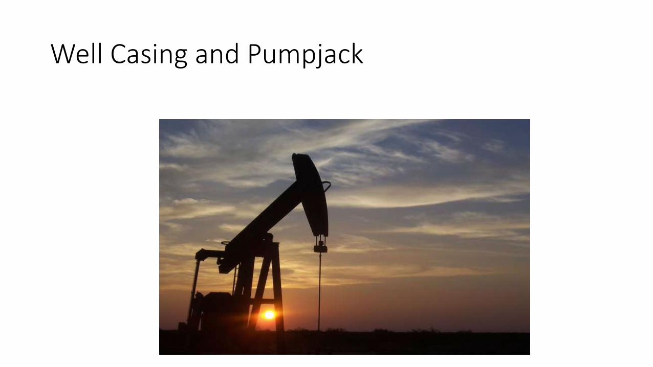
Well Casing and Pumpjack
Discussion
Cathodic protection has been used for protecting well casings from external corrosion for decades. The process is simple but the application can be complex. The primary purpose is to prevent casing leaks. A casing leak on a production or storage well is an expensive repair that can be minimized via the application of CP.Economics: The primary reason for most owner/operators is economical. Every well has a design life and depending on the life, the time to leak is determined and if less than the design life – installing CP becomes economical as it will prevent leaks for the design life of the well. If the well has a finite life and the time to leak is greater than the finite life then CP may not be necessary. The issue is most wells are run beyond their design life and enter the time to leak zone. Many owner/operators realize this or operate storage wells which have a long life well beyond the predicted time to leak and CP becomes a viable economic option.
Discussion - continued
Cathodic protection can be used for protecting various types of wells and their casings from external corrosion. This includes oil and gas production wells, storage wells for natural gas and natural gas liquids, salt dome storage well casings, observation wells, monitor wells, water wells, disposal or injection wells and special wells. A casing leak on any well is an expensive repair that can be minimized via the application of CP.Logistics: Applying CP to a well casing is normally a fairly simple process. Install a cathodic protection anode bed (deep or surface) and connect it to a DC power source and the power source to the well casing. The process gets complicated when determining which power source to use, where to locate the anode bed, how to address the flow line from the well, how to address the other utilities in the vicinity and how to address the ongoing operations and maintenance costs for the CP system.That’s is where the corrosion control professionals are needed.
Typical Wellhead – Well Casing
Isolation Flange
SAND & FRESH WATER
SANDSTONE & SALT WATER
LIMESTONE
WELL CASING
FLOWLINE
Corrosion Issues – CP Can Solve These Issues
External corrosion: Well casings leak due to external and internal corrosion. CP will minimize or stop external corrosion. The forms or processes of external corrosion are as follows:
Long Line Corrosion – current flowing in different directions or off the well casing due to the different formations that the well casing traverses. This current flow causes corrosion when the current departs the well casing.
Localized Corrosion – current flowing off and on the casing at couplings with exposed threads or formation changes due to high/low resistivity.
Corrosion Issues - continued
Stray Current – various stray current sources – predominately foreign CP current or the owner/operators pipeline/flowline/tank bottom CP systems can cause stray current.
Casing Installation – the installation of the casing can also cause corrosion depending on the handling of the casing and the method of installation as accidental removal of the casing varnish, tongs and chains can remove varnish and scratch the external surface and corrosion can result. Also, the mixture of the drilling mud can contain various materials such as chlorides, sulfides or some additives which will create a corrosive environment, a low resistivity environment or both.
CP Design IssuesElectrical Isolation of well flow line. This is mandatory if one is providing CP for the well casing. This allows the majority of the CP current to go to the well casing as well as minimize any stray current pick up on the flow line.
Connecting the rectifier negative cable directly to the well head/well casings. Connecting the negative directly to the casing again allows the majority of the CP current to flow onto the casing and return via the direct connection. It provides a low resistance path. This can be critical as we want the CP current to flow up the casing to the negative cable and return to the rectifier.
Electrical continuity of the surface casing, production casing, tubing, etc. Electrical continuity between the well components at the wellhead is also critical as this will minimize CP current passing between the components downhole. Electrical continuity at the wellhead and a separate negative cable at the wellhead will allow the majority of the CP current to travel up the casing and to the negative return.
Determining current requirement of the well casing
The level of current – milliamps per square foot of surface area needs to be determined. This is based on what the soil conditions are downhole, the temperature of the product, variation in the formations the well casing transgresses and reviewing the drilling log if available. The typical ranges go from 1 to 3 milliamps per square foot with 2 milliamps as the most common.
Then the actual CP current required can be calculated several ways:
• Calculating the actual surface area of the casing and then multiplying it by 2 milliamps per square foot.
• Performing E log I testing on the well casing to get an actual current value.
• Running a casing potential profile log using a temporary CP source to get an actual current value.
Well Casings – The Early Days
CP System Design Issues
Well casings are typically protected with an impressed current CP system –either a remote surface anode bed or a deep anode. The optimum location for the surface anode bed/deep anode is at remote earth. At remote earth, the anode bed/deep anode provides the best current distribution for the entire well casing. If installed too close to the well casing, then poor current distribution will result. Typically, remote earth is obtainable at approximately 500 feet from the structure.
Two issues arise when determining which type of CP system – surface anode bed/deep anode and the location for the anode bed.
• Area required for a surface anode bed – length and width.
• Procuring area for a remote anode bed - deep or surface – distance from structure.
Design Issues - continued
• AC power
• Multiple well casings on the same drilling pad
• Deep anode depth vs. current distribution
• CP Interference
• Cellar at Wellhead
Current Distribution
Current Distribution – Deep Anode
Bed
LOW
RESISTIVITY
+-
DEEP
ANODE
BED
RECTIFIER
HIGH
RESISTIVITY
WELL CASING
LOW
RESISTIVITY
Current Distribution – Remote
Anode Bed
+-
REMOTE
ANODE
BED
RECTIFIER
WELL CASING
Case History
• Multiple wells on one pad and a single CP system.
• Balancing the CP System
• Adding Resistance
• Negative Control Box
• Low Resistance Path
• Casing Leak
Background
A producer installed a single well on a well pad. The CP system was designed to accommodate 3 future wells being installed on the same pad. The CP system was rated 50 DC amperes and used a deep anode installed 100 feet from the well.
Over the next few months 3 additional wells were installed on the pad and all were tied into the CP system. Each well had had a negative cable installed and run to the rectifier. The rectifier had a four-circuit negative junction box installed so all the well casing CP current returns could be monitored.
Background - continued
Initially for well #1 the CP system was set at 10 amperes. The design current was 8.7 amperes. As the 3 additional well casings were tied into the CP system, the current output of the rectifier was increased in 10 ampere increments until the rectifier ended up operating at 49 amperes. After some time, the local corrosion engineer got involved and took some shunt readings at the negative junction box and found the following:
• Well #1 - 22 amperes
• Well #2 - 16 amperes
• Well #3 – 6 amperes
• Well #4 - 5 amperes
Background - continued
After a few months, the corrosion technician and the contract corrosion engineer evaluated the CP system at the four well pad and realized they had quite an imbalance in the negative return current and two of the well casings were not receiving adequate CP current. A decision was made to install a negative control box and replace the negative junction box. A negative control box is basically a negative junction box with resistors installed for each circuit. The rectifier was also adjusted to a DC output of 44 amperes.
Background - continued
The negative control box was installed and resistance was added to the well #1 negative return and the current flow reduced from 22 amperes to 11 amperes.
• The return current from the four wells was now:
• Well #1 – 11 amperes
• Well #2 – 18 amperes
• Well #3 – 8 amperes
• Well #4 – 8 amperes
Typical Negative Control Boxes
Background - continued
Resistance was then added to the well #2 negative return and the current reduced to 10 amperes.
The return current from the four wells was now:
• Well #1 – 12 amperes
• Well #2 – 10 amperes
• Well #3 – 10 amperes
• Well #4 – 11 amperes
The rectifier was running at 44 amperes.
The technician reread the negative control box one year later and the outputs were about the same.
Background - Continued
Six months later well #1 had a leak. The well was shut in and the tubing and casing pulled and a 100-foot section of the casing was found to have severe pitting corrosion. The cause appeared to be the CP current was discharging from well #1 to wells #3 & #4 through the soil. This location had a fairly low resistance formation and the CP current was flowing through that path to return the CP current to the rectifier. The path had a much lower resistance than the resistance of the control box resistor.
Lesson Learned
Do not install too much resistance in a CP circuit as the CP current will always find the lowest resistance path back to the current source.
Solution that was designed and commissioned by the new contract corrosion engineer was to install a new deep anode at remote earth from the wellheads – approximately 500 feet away. The deep anode was installed at a depth of 400’. The negative control box and the existing deep anode was abandoned and a new negative junction box installed at the rectifier with NO resistors.
Lesson Learned - continued
The current distribution was the following for the new CP system:• Well #1 – 10 amperes• Well #2 – 11amperes• Well #3 – 10 amperes• Well #4 – 10.5 amperesRectifier current output was at 43 amperes.Cost of this corrosion failure - $1.2 million dollarsCost to install a properly designed CP system - $42,000.Note: Well #2 was also shut in some time later and inspected and severe (but no failure yet) corrosion was discovered at the same zone as the well #1 failure. Casing and tubing were replaced as part of routine maintenance.
Conclusions
Cathodic protection of well casings is a practical and economical method of minimizing or even stopping corrosion. The concept is not complex; however, the application, design and installation are complex and need to be performed by a competent CP professional.
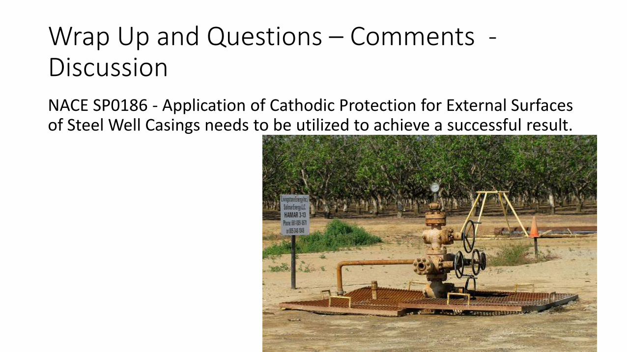
Wrap Up and Questions – Comments -DiscussionNACE SP0186 - Application of Cathodic Protection for External Surfaces of Steel Well Casings needs to be utilized to achieve a successful result.