3Umar Iqbal and 4Naser El-Sheimy 1Department of Telemetry and Surveying Engineering, Schlumberger Houston, Texas
2Department of Electrical and Computer Engineering, Royal Military College of Canada, Queen’s University, Canada
3Department of Electrical and Computer Engineering, Queen’s University, Canada 4Department of Geomatics Engineering, University of Calgary, Alberta, Canada
Abstract: Problem statement: Oil and gas are global fuels obtained primarily from drilling wells in underground terrestrial reservoirs. Vertical drilling is preferred because of its simplicity and therefore low cost, but subsurface targets can often be procured only by directing the wellbore along predefined non-vertical trajectories. For instance, directional drilling must be employed to reach locations inaccessible to the drilling rig, to side track an existing well (multilateral drilling), or to drill multiple wells from the same offshore platform (horizontal drilling). Approach: A complete knowledge of the wellbore direction and orientation during the drilling process is essential to guarantee proper directional drilling procedure. Results: Thus, besides the conventional drilling assembly, directional drilling operations require sensors to provide azimuth, inclination and toolface angles of the drill. These sensors are part of the Measurement-While-Drilling (MWD) tool, which in current technology is installed several feet behind the drill bit. In such systems, values for inclination and toolface angles are determined from accelerometer measurements at predetermined stationary surveying stations; these values are then incorporated with magnetometer measurements to deliver the azimuth angle. Values for inclination and azimuth angles at the current surveying station are combined with those from the previous station to compute the position of the probe. However, there is no accurate information about the wellbore trajectory between survey stations. Additionally, the magnetic field of the magnetometers has deleterious effect on the overall accuracy of surveying measurements. Conclusion: A method to provide continuous information about the wellbore trajectory has been developed in this study. The module developed integrates a Rotary Steerable System (RSS) and MWD tool into one drilling probe utilizing Inertial Navigation System (INS) technology. This is achieved by designing a reliable real-time low cost MWD surveying system based on MEMS inertial sensors miniaturized inside the RSS housing installed directly behind the drill bit. A continuous borehole surveying module based on MEMS inertial sensors integrated with other drilling measurements was developed using Kalman filtering. Key words: Wellbore surveying, measurement while drilling, Rotary steerable system, MEMS-based
inertial sensors, Kalman filter
INTRODUCTION Directional drilling is the science of directing a wellbore along a predefined trajectory leading to a subsurface target (Bourgoyne et al., 1986). Directional drilling is essential for many reasons such as inaccessible surface locations to the drilling rig, side tracking of an existing well, drilling multiple wells from the same offshore platform, multilateral drilling and horizontal drilling. Additionally, horizontal wells have higher oil and gas deliverability where they have
larger contact area with oil and gas reservoirs (Joshi and Ding, 1991). This in turn substantially reduces the cost and time of drilling operations. Thus, in recent years, the development of directional well drilling technologies has gained more attention than improvements in vertical drilling technologies in Canadian global oil and gas industries. Current MWD surveying is performed along the well path at stationary survey stations. The well path computation is based on three measurements repeated at each surveying station. They are the drilled length,
Am. J. Engg. & Applied Sci., 3 (2): 240-259, 2010
241
inclination and azimuth. In addition, the orientation of the survey instrument inside the hole (toolface) is determined after deviating from the vertical direction of the well. There are two conventional systems for measurements while drilling based on magnetometers and gyroscope. The strengths and limitation of these systems are discussed below. Magnetometers based system: Present MWD tools employ three orthogonal fluxgate saturation induction magnetometers inside the direction and inclination sensors package (Bourgoyne et al., 1986). The earth’s magnetic field can be measured using magnetometers and the magnetic azimuth angle can be derived. Magnetometers require a nonmagnetic environment in order to function properly, as the measured azimuth is referenced to the magnetic north (Ripka, 2001). Magnetometers are sensitive to the earth’s magnetic field; each magnetometer has two primary coils and a pick up secondary coil surrounds the primary coils. An alternating current passes through the two primary coils; symmetrical voltage pulses are then generated in the secondary coil each time the AC current changes direction. However, if an external magnetic field exists, it can distort the voltage pulses in the secondary coil. The magnetometer reacts by supplying a buckling current through the second coil to drive the voltage pulses back to their symmetric state. The magnitude of the buckling current is proportional to the earth’s magnetic field strength and aligned to the axis of the magnetometers (Ripka, 2001). The magnetic field strength has horizontal and vertical components. The horizontal component points from the magnetic north to the magnetic south, while the vertical component points down into or up out of the ground. We rely mainly on the horizontal component to calculate the magnetic azimuth direction of the BHA. The horizontal component is small close to the poles and errors introduced due to magnetic interference significantly affect magnetic azimuth measurements (Parkinson, 1983). The most important challenge the current magnetometer MWD tools encounter is magnetic interference and Bottom Hole Assembly (BHA) sag. Two types of magnetic interference disturb magnetometer readings. The first is the drill string magnetic interference and the second is the external magnetic interference due to the surrounding environment. The drill string can be considered as a long slender magnet that has both ends acting as magnetic poles. As a result, drill string steel components become magnetized due to the presence of the earth’s magnetic field lines. A magnetometer based MWD tool is
therefore placed inside a nonmagnetic drill collar in an effort to eliminate this effect, but the nonmagnetic drill collar can only minimize the influence of the other steel components in the drill string (Thorogood and Knott, 1990; Grindord and Wolf, 1983). As the inclination angle builds up from the vertical direction or the direction of the bore hole (azimuth angle) deviates away from the north-south direction, the effect of magnetic interference on magnetometer measurements due to the drill string increases significantly (Thorogood and Knott, 1990). Drill string magnetic interference only affects magnetometer measurements aligned along the tool rotation axis, assuming the three magnetometers are orthogonal. Unlike drill string magnetic interference that affects only one magnetometer, the external magnetic interference affects all three magnetometers in the triad. External magnetic interference can be introduced by the following: (1) Presence of Iron, pyrite and hematite formations and ferromagnetic material near the tool such as nearby casing collars greatly affects magnetometer measurements (Bourgoyne et al., 1986). (2) Solar storms and diurnal variations of the field greatly affect magnetic azimuth accuracy and hence magnetometer measurements must be corrected for these effects (Thorogood and Knott, 1990; Wolf and De Wardt, 1981). (3) Drilling fluid can degrade the magnetic azimuth accuracy if it contains magnetized contaminants. (4) When a nonmagnetic drill collar exceeds its magnetic tolerance, magnetic hot spots develop and the nonmagnetic drill collar has to be replaced (Zijsling and Wilson, 1989). BHA sag refers to a misalignment along the MWD tool rotation axis and the well bore centre axis, where the MWD tool does not lie centrally inside the borehole. The MWD tool tends to lie on the low side of the borehole due to gravitational forces acting on the drill string. The sag relies on BHA design, number and sizes of stabilizers, position and degree of bend of the steerable motor, mud weight and the borehole inclination angle. The effect of BHA sag on the direction and inclination sensors package can be significant and leads to a large system error especially in a wellbore with high inclination. Thus, measurements have to be corrected for this error (Berger and Sele, 1998). Gyroscope based system: A gyroscope measures angular velocity and is used for monitoring angular rotation along the sensitive axis of a MWD tool sensor. Gyroscope technology is used in some directional drilling applications, however, it is not utilized in RSS technology and it has limited use in MWD tools. The advantage of gyroscope technology is that interruptions
Am. J. Engg. & Applied Sci., 3 (2): 240-259, 2010
242
in the earth’s magnetic field or surrounding magnetic interference has no effect on gyroscope performance. At present, gyroscopes are utilized in hole orientation tool, single-axis and double-axes based MWD tool. Recent research has investigated three types of gyroscope sensors to be employed in MWD tools. They are the Mechanical Based Gyro (MBG), the Ring Laser Gyro (RLG) and the FOG. Performance of the MBG is unacceptable due to moving parts that are susceptible to shock and vibration while drilling. The RLG is a navigation grade gyroscope used mainly in commercial and military aircraft as a primary navigation sensor due to the high accuracy and the relatively small error drift rate of this sensor. The RLG gyroscope sensor is expensive and has limited use because its large size makes it difficult to install inside the MWD tool collar. Cost and size restrict the use of RLGs in measurement-while-drilling applications (Estes and Epplin, 2000). The FOG is relatively smaller than the RLG and the FOG’s susceptibility to shocks and vibrations is lower than that of the MBG. However, a complete set of three orthogonal FOGs cannot be installed in a MWD tool collar due to the size of the instruments. Efforts have been made to solve this problem by using a single axis gyroscope with a dual axes gyroscope in MWD applications (Noureldin, 2002; Binder et al., 2005). A single axis FOG gyroscope is integrated with three orthogonal accelerometers in order to continuously measure the azimuth, tool-face and inclination of the well bore. It is based on the assumption that the changes in inclination and toolface are very small if they are monitored at a high rate. Because the sensitive axis of the gyroscope is along the MWD tool rotation axis, the tool can only detect the tool direction while the bore hole is vertical or nearly vertical. In faster drilling formations, the inclination build up rate angle can reach up to 40°/h (Joshi and Ding, 1991). The single axis gyroscope MWD tool cannot be relied on in such a condition (Noureldin, 2002). In summary, a single axis gyroscope MWD tool is limited to drilling a bore holes in vertical and near vertical directions, with slow build up rate angles. An MWD tool with a dual-axes spinning mass Gas Bearing Rate (GBR) gyroscope with a stepper motor-driven indexing mechanism has been developed (Estes and Epplin, 2000). A limitation of this tool is the use of an indexing motor in order to rotate the gyroscope around its spin axis. The motor moves the sensors chassis to a set of positions to estimate the run to run bias of the sensor measurements. Field tests failed due to the failure of the indexing motor, where a coupling fracture between the indexing motor and the sensor chassis prevented the motor from rotating properly
(Estes and Epplin, 2000). A stationary based surveying technique was implemented at certain stations. The tool was not able to provide continuous azimuth, inclination and toolface measurements while drilling, which imposed another limitation. A third limitation is that dual-axes gyroscopes cannot resolve well bore azimuths for horizontal drilling; this is a problem when the inclination is 60° and higher (Estes and Epplin, 2000). Another implementation of dual-axes gyroscopes MWD tools has been proposed, but with the use of two FOGs instead of GBR gyroscopes. The study proposed an improved algorithm to derive the continuous azimuth at highly inclined and horizontal sections of the well (Noureldin, 2002). This was accomplished by changing of the gyroscopes body axes orientation at high inclination sections. In a different study, two dual-axes gyroscopes were integrated with three orthogonal accelerometers. However, the gyroscopes were arranged in the cross-section plane of the borehole and an inclinometer system with a transverse gyroscope was developed (Binder et al., 2005). An indexing motor was utilized in the research to calibrate the gyroscope at surveying stations. The motor rotates the gyroscopes’ housing about two mutually perpendicular axes. The last two studies have not been field tested yet. Rotary steerable system technology: The Rotary Steerable System (RSS) is a recent technology that allows drilling at faster rates by rotating the entire drill string all the time. This differs from conventional technology that uses a PDM with a bent housing to provide a side force to the bit to deflect the well bore in the desired direction. In conventional technology, drilling is done in sliding and rotary modes. A sliding mode is defined when the entire drill string is not rotating and only the drill bit is rotating. This takes advantage of the bent housing in the PDM to divert the well bore to a desired direction. As soon as the well bore direction and build angle are established, drilling enters into a rotary mode where the entire drill string rotates to hold direction. The sliding mode is considerably slower than the rotary mode and is associated with many problems. The emerging RSS technology is highly desirable because it completely eliminates sliding problems and has several additional advantages (Edmondson and Chris, 2002) which can be listed as: (1) Increase the rate of penetration of the drill bit to allow faster directional drilling. (2) Help optimize drilling parameters such as weight on bit and Revolutions Per Minute (RPM), which optimizes drilling operation. (3) Improve the wellbore quality and provide an in gauge hole with no ledges; it also reduces wellbore tortuosity (Weijermans et al.,
Am. J. Engg. & Applied Sci., 3 (2): 240-259, 2010
243
2001). (4) Reduce the torque and drag that cause fatigue of the drill string. (5) Provide better wellbore cleaning, where the continuous rotation of the drill string agitates wellbore cuttings in the annulus; this facilitates moving the cutting out of the hole. If using the conventional PDM, additional wiper trips are needed for the hole cleaning after drilling is completed. Therefore, RSS eliminates the additional time required for wiper trips. (6) Eliminate the time of the toolface orientation at each tool joint when using the conventional PDM. (7) Eventually decrease the cost per foot of drilling operations. An RSS can turn the wellbore while rotating by pushing or pointing the bit toward the desired direction using a shaft drive attached to the bit. Each directional drilling service company has a unique design to mechanically control the bit direction while drilling. RSS challenges: Recent advances in RSS technology increased the demand for the use of MWD technology for directional control of the well bore. However, the RSS is installed directly behind the bit followed by the MWD tool. This leads to an offset of at least 15 m between the current MWD surveying sensors package and the bit, as shown in Fig. 1. The average drill bit length is 300 mm and the average length of an RSS (Fig. 1C) is 8 m. The flex sub (Fig. 1B) and the spiral stabilizer extend for 6-9 m. The MWD collar (Fig. 1A) length is approximately 9 m. The surveying sensor package is usually installed on the lower part of the MWD tool collar.
Under these conditions drilling proceeds blindly for 15 m and the directional driller has to wait to drill 50 feet to know the location of the wellbore. An average formation can be drilled at a rate of 10 ft/h, this count for 5 h of drilling blindly. This leads to a high cost if the wellbore is diverted significantly from the planned trajectory especially for offshore operations. Additionally, MWD tools available in the market cannot provide a continuous wellbore trajectory while drilling. Furthermore, the MWD tool does not communicate its measurements to the RSS while drilling. If the RSS does not deviate in the correct direction, drilling has to stop and different commands have to be down-linked to the RSS. This is indeed very time consuming and imposes constraints on the use of an RSS. Thus, the full advantages of the RSS are yet to be realized with the present implementation. This shortcoming of the current technology has motivated this research study. Objectives: The aforementioned challenges of the current technologies available for the hydrocarbon drilling industry and the potential for significant improvements have motivated this research study. It aims to develop an integrated solution to enhance directional drilling by integrating an RSS with MWD direction and inclination sensors and packaging the two systems into one collar installed less than 1.5 m behind the drill bit. This study proposes an advanced direction and inclination sensor package based on the Inertial Navigation System (INS). The strict size limitation inside the RSS collar makes MEMS inertial sensors perfect candidates for this application.
MATERIALS AND METHODS MEMS inertial sensor are utilized in this study to enable RSS and monitoring of position and attitude of the drill fit due to their small size, light weight, low power consumption and immunity to shock and vibration. INS mechanization equations are implemented to derive a continuous wellbore trajectory. The inputs to the mechanization equations are the accelerometer and gyroscope sensor measurements, while the outputs are position, velocity and attitude of the platform where the inertial sensors are installed (Titterton and Weston, 1997). INS mechanization equation outputs are derived with respect to a specific reference frame. When installing the inertial sensors inside the rotary steerable system closely behind the drill bit, the accelerometer triad measures the accelerations of the drill bit in three orthogonal directions, the directions of the sensitive axes of the
Am. J. Engg. & Applied Sci., 3 (2): 240-259, 2010
244
accelerometers which coincide with the axes of the rotary steerable system. At this stage, all measurements will be taken in reference to these axes which are known as the body frame. In addition to accelerometer measurements, gyroscope measurements are essential to determine the orientation of the drill bit with respect to the navigation frame. This is achieved by integration of the gyroscope measurements and knowledge of the initial attitude angles which are the pitch, roll and azimuth (Titterton and Weston, 1997). The attitude angles need to be known in order to transform the accelerometer measurements from the body frame to the navigation frame. If the initial velocity of the drill bit in the three orthogonal directions is known, the continuous velocities in the navigation frame can be determined by the time integral of each transformed acceleration component. The second integration derives the drill bit position in the navigation frame with respect to the initial position. It must be noted that accelerometer readings are contaminated by the earth’s gravitational field. The acceleration of gravity is added to the accelerometer measurements. Therefore, it is crucial to know the exact acceleration of the earth’s gravity at the location where the accelerometer will be run. This will separate the acceleration due to the earth’s gravitational force from the acceleration due to the drill string motion. Transformation between coordinates frames: The accelerometer and gyroscope sensors are mounted inside the rotary steerable system collar and their sensitive axes are aligned toward the forward direction (y), the transverse direction (x) and the (z) direction perpendicular to the xy plane. These three axes form the body frame (b-frame). Illustration of the b-frame inside the rotary steerable system collar is presented in Fig. 2.
Fig. 2: Body frame (drill string frame) axes of the
rotary steerable system
Therefore, the original accelerometer and gyroscope measurements represent the linear acceleration and angular velocities in the b-frame. However, the measurements are normally transformed into the navigation reference frame in order to provide the position, velocity and attitude of the moving drill bit and drill collars. Main benefit of selecting the n-frame is, the azimuth, inclination and toolface angles of the drill collar are obtained directly as outputs of the INS mechanization equation in the n-frame. Another advantage of using the n-frame is computational errors of the navigation parameters in the north-east plane are bound (Titterton and Weston, 1997; Mohamed, 1999), where they are coupled together and produce the Schuler loop. These errors oscillate with a Schuler frequency of 1/5000 Hz. As stated earlier, accelerometer and gyroscope measurements are taken in the body frame (b-frame). The matrix n
bR is used to transform these measurements
into the navigation frame. nbR is a combination of
azimuth (ψ), pitch (θ) and toolface (ξ) angles; it is expressed as follows:
nb
cos cos sin sin sin sin cos
sin cos cos sin sin cos cos
cos sin sinRcos sin sin sin cos
sin sin cos sin cos
cos cos
ψ ξ + ψ θ ξ ψ θ − ψ ξ + ψ θ ξ ψ θ − θ ξ θ=
ψ ξ − ψ θ ξ − ψ ξ − ψ θ ξ θ ξ
(1)
Accordingly, transformation of the measurements from n-frame to b-frame can be implemented by using the inverse of the transformation matrix n
bR .
Mechanization equations: The inertial measurements unit provides three angular velocity b T
ib x y z( )ω = ω ω ω
and three acceleration b Tx y zf (f f f )= measurements
measured in the tool body frame. The specific forces fb are then projected on the navigation frame using the rotation (direction cosines) matrix. The angular increments b T
ib x y z( )θ = ∆θ ∆θ ∆θ can then be
determined using the angular velocity measurements. The linear velocity increments x y z( )∆ν ∆ν ∆ν are
obtained similarly using the three acceleration measurements. The derived angular increments capture the drill collar angular increments in addition to the earth’s rotation and the change of orientation of the navigation frame with respect to the earth-fixed frame. The last
Am. J. Engg. & Applied Sci., 3 (2): 240-259, 2010
245
two effects must be taken into account. Their expression b
inω is derived in Eq. 2. The angular
increments can then be presented at a given time kt as
in the following expression:
n
k
eb b b ekin k in k n k
eek
V (t )
M hV (t )
(t ) (t ) t R (t ) cos tN h
V (t ) tansin
N h
− +
θ = ω ∆ = + ω φ ∆ + φ + ω φ +
(2)
It is possible now to determine the actual angular increment of the drill string at a given time b
nb k(t )θ by
subtracting and compensating for bin k(t )θ from the
original bib k(t )θ as follows:
xb b bnb k ib k in k y
z
(t ) (t ) (t )
∆θ θ = θ − θ = ∆θ ∆θ
(3)
The following step updates the quaternion vector. The initial quaternion vector 0Q(t ) is computed using
the initial rotation matrix nb 0R (t ) derived from the
initial alignment during a stationary period. The quaternion vector is updated by using Eq. 4 applied as:
z y x1 k 1 1 k
z x y2 k 1 2 k
y x z3 k 1 3 k
x y z4 k 1 4 k
1 k
2 k
3 k
4 k
0q (t ) q (t )
0q (t ) q (t ) 10q (t ) q (t ) 2
0q (t ) q (t )
q (t )
q (t )
q (t )
q (t )
+
+
+
+
∆θ −∆θ ∆θ −∆θ ∆θ ∆θ = + × ∆θ −∆θ ∆θ −∆θ −∆θ −∆θ
(4)
The updated rotation matrix n
bR is determined
afterward from the direct relationship with the updated quaternion vector in Eq. 4. Finally the azimuth (ψ), toolface (ξ) angles and pitch pitch (θ(90-inclination I)) of the drill string can be derived using the relationship explained before. As a result they are obtained using the following expressions:
12
22
rarctan
r
−ψ =
(5)
31
33
rarctan
r
ξ =
(6)
32
2 212 22
rI 90 90 arctan
r r
= − θ = − +
(7)
The following step updates the velocity components at tk+1. This can be accomplished by using Eq. 8 to determine drill string velocity changes along the navigation frame as follows:
( )n n b n n n nk 1 b ie enV (t ) R v 2 V t g t+∆ = ∆ − Ω + Ω ∆ + ∆ (8)
Finally, the updated velocity components
( )n east north upV V V V= at tk+1 are derived using a direct
relationship with nk 1V (t )+∆ :
( )n n n nk 1 k k k 1
1V (t ) V (t ) V (t ) V (t )
2+ += + ∆ + ∆ (9)
The updated positions (latitude φ, longitude λ and true vertical depth h) of the drill string at tk+1 are computed using modified Euler formulas. h is computed using the relationship with the vertical component of the velocity vector in Eq. 9. It is expressed as:
( )up upk 1 k k k 1
1h(t ) h(t ) V (t ) V (t ) t
2+ += + + ∆ (10)
Equation 11 and 12 compute the drill string latitude φ longitude λ, at tk+1:
( )north northk k 1
k 1 k
V (t ) V (t )1(t ) (t ) t
2 M h+
+
+φ = φ + ∆
+ (11)
( )( )
east eastk k 1
k 1 k
V (t ) V (t )1(t ) (t ) t
2 N h cos+
+
+λ = λ + ∆
+ φ (12)
The continuous update of the drill string position, velocity and attitude angles are computed using the measurements from the accelerometer triad and the gyroscope triad without regard to contaminating errors. However, the long term accuracy deteriorates due to integration of accelerometer and gyroscope sensor errors and computational errors. Drill bit synthetic attitude angles: In a stationary mode, the pitch and toolface of the drill bit can be derived using only accelerometer measurements based on the following relationship between the accelerometer measurement vector fb and the gravity vector gn:
Am. J. Engg. & Applied Sci., 3 (2): 240-259, 2010
246
xb b n b
y n n
z
f 0
f f R g R 0
f g
= = = −
(13)
where gravity vector gn is derived from the normal gravity model. The rotation matrix b
nR transforms the
gravity vector defined in the n-frame into the b-frame and it is expressed as in Eq. 1. Accelerometer measurement vector fb can be written as:
xf gcos sin= θ ξ (14)
yf gsin= − θ (15)
zf gcos cos= − θ ξ (16)
According to Eq. 14-16, the pitch θ and toolface ξ angles can be derived as:
yfsin
gθ = − (17)
x
z
ftan
fξ = − (18)
When the drill bit rate of penetration is very slow, synthetic pitch and toolface angles can be derived by using only the accelerometer measurements as shown in Eq. 17 and 18. The comparison with drill bit inclination and toolface reference angles is presented in the following discussion. Surveying error modeling using linear state equations: Surveying errors must be estimated to a certain level in order to achieve an acceptable system performance. Given the nonlinear nature of the system, the system is perturbed in order to derive a set of linear differential equations. This is done using the linearization approach of the nonlinear dynamic system (Jekeli, 2000). The surveying errors of the coordinate errors ( h)δφ δλ δ , velocity errors e n u( V V V )δ δ δ and
attitude errors ( )δψ δθ δξ can be derived (ElGizawy,
2009). Inertial sensor measurements contain biases and constant drifts defined as the deterministic parts, which are determined by field calibration. The remaining errors are considered random and modeled as stochastic processes, where these errors are correlated in time and modeled as first order Gauss-Markov (GM) processes (ElGizawy, 2009). Measurement errors of the inertial
sensors are known to drift with time in the absence of external measurement updates. This error growth is limited by applying an optimal estimation tool such as Kalman filtering. Kalman filtering algorithm: The Kalman filter is a computational algorithm that deduces a minimum error estimate of the state of a system by considering the dynamics of the system, characteristics of the system noise, measurements errors and the initial condition information. Inertial sensor errors and surveying errors are combined to form the error state vector Xk at time tk:
e n u
ky yx z x z
h V V Vff f
δφ δξ δλ δ δ δ δ δθχ = δω δδω δω δ δδψ (19)
The sequential recursive algorithm of Kalman filtering for the optimal least mean variance estimation of the error states is best described by the following Fig. 3. Drilling observation updates for Kalman filtering: The proposed drilling surveying system will exhibit an unlimited growth of position, velocity and attitude errors if there are no external observations to update the surveying system. Two external update schemes can limit the error growth of the inertial sensor measurements while drilling. The first is based on the continuous source of drilled pipe length measurements which can be used to determine the drill bit rate of penetration. This can be further translated to the continuous velocity measurements’ update of the inertial sensor measurements. Additionally, a continuous position is applied based on the position computed by the MCM (ElGizawy et al., 2006). The second external update scheme is based on stationary measurements taken when the drilling operation stops on a regular basis to connect a new stand of pipes. Stationary updates are Zero velocity Updates (ZUPT), stationary MCM position updates, as well as magnetic heading angle updates. The inertial sensor measurements and the observation updates are processed through the Kalman filter algorithm to optimally estimate the surveying parameters as Fig. 4. The efficiency of these observation updates depends on the accuracy of these observations and on the how often they are available. Continuous surveying observations updates while drilling: The rate of penetration of the drill bit while drilling is available continuously by making use of the information of the drilled pipe length and time. The drilled pipe length measurement is based on the measurements of the drill line movements by monitoring
Am. J. Engg. & Applied Sci., 3 (2): 240-259, 2010
247
Fig. 3: Block diagram of the Kalman filtering sequential recursive algorithm
Fig. 4: Drilling scheme of Kalman filtering revolutions of the draw works drum to record incremental additions to the drill string. This is done with an optical encoder installed on the drum of the draw works. The pulses per foot measured by the encoder vary at each wrap on the draw works. This is compensated for by calibrating the total number of pulses per wrap to the corresponding depth variation as the block is pulled up. Depth is incremented only when the drill pipes are moving. When making a connection while the drill string is stationary, depth updates stop (Bourgoyne et al., 1986). The velocity obtained from the INS
( )e n uINS INS INSV V V is compared to the drill bit rate of
penetration ( )e n nupdate update updateV V V . The continuous
MCM position updates ( )update update updatehφ λ are based
on a valid assumption that the well trajectory between the two surveying stations lies on a circular arc and position computations are based on the minimum curvature method (Taylor and Mason, 1972). Based on this information, the Kalman filter estimates the random errors within the INS output. In turn, it enhances the
performance of the surveying system while drilling by removing the estimated errors from the inertial sensor measurements (ElGizawy et al., 2006). The observation vector Zk is presented as:
INS update
INS update
INS updatee ekINS updaten nINS updateu uINS update
h hZ
V V
V V
V V
φ − φ λ − λ − =
− − −
(20)
The design matrix Hk that exhibits the noiseless relationship between the observation vector Zk and the error state vector Xk is written as:
3 3 3 3 3 3 3 3
k
3 3 3 3 3 3 3 3
1 0 0
0 1 0 0 0 0 0
0 0 1H
1 0 0
0 0 1 0 0 0 0
0 0 1
× × × ×
× × × ×
=
(21)
Am. J. Engg. & Applied Sci., 3 (2): 240-259, 2010
248
The values of the observation vector Zk and the design matrix Hk provides the Kalman filtering measurement update equation of the drill bit rate of penetration and the MCM position:
INS update
INS update
INS updatee eINS updaten nINS updateu uINS update 6 1
3 3 3 3 3 3 3 3
3 3 3 3 3 3 3 3
6 15
h h
V V
V V
V V
1 0 0
0 1 0 0 0 0 0
0 0 1
1 0 0
0 0 1 0 0 0 0
0 0 1
×
× × × ×
× × × ×
×
ϕ − ϕ λ − λ − =
− − −
×
δϕδ
e
n
u
6 1
x
y
z
x
y
z 15 1
h
v
v
v
v
f
f
f
×
×
λ δ
δ δ
δ δθ +δξ
δψ δω
δω δω δ δ δ
(22)
The second term on the right hand side represents the uncertainty of the drill bit rate of penetration and MCM position measurements. When the drilling stops in order to connect new pipe stands, stationary external observations are utilized that is discussed in detail as follows: . Stationary surveying observation updates: In large drilling rigs, drilling has to stop every 30 m for at least 5-10 min in order to connect a new drill pipe stand. In smaller drilling rigs, drilling stops every 10 m for the same purpose. During this period, stationary measurements are applied as observations updates to the INS.
The first stationary update is the Zero velocity Update (ZUPT). In reality, the drill string is stationary; any velocity output of the inertial surveying system is accelerometer bias errors. This information is fed into the Kalman filter in order to estimate and remove the velocity errors. The design matrix Hk of the observations update equation is expressed in Eq. 23, while the observation vector Zk is expressed in Eq. 24:
k 3 3 3 3 3 3 3 3
1 0 0
H 0 0 1 0 0 0 0
0 0 1× × × ×
=
(23)
e e eINS ZUPT INSn n n
k INS ZUPT INSu u uINS ZUPT INS
V V V 0
Z V V V 0
V V V 0
− −
= − = − − −
(24)
Drill string heading observations are obtained from a magnetometer triad that is able to provide heading observations only while the drill string is stationary (ψupdate). The magnetic heading is referenced to the magnetic north and the gyroscope heading is referenced to the true north, therefore, the magnetic heading has first to be corrected to reference to the true north before it is compared to the heading derived from the gyroscope. This is done by applying a magnetic declination correction to the magnetic heading. The magnetic declination is defined as the angle between the true and magnetic north as measured from the true north. Its value depends on the location and time of applying the correction; the correction is usually obtained from the British Geological survey global Geo-Magnetic (BGGM) Model. The heading observation after referencing to the true north ψupdate is used as a direct observation update in Kalman filtering to estimate the random errors in the measurement of the inertial derived heading ψINS. The relationship between the observation vector Zk and the error state vector Xk are contained within the design matrix Hk as:
( )k 1 3 1 3 1 3 1 3H 0 0 0 0 1 0 0× × × ×= (25)
In addition to utilizing the heading observation as a direct update, it is utilized along with the inclination of the drill string during the stationary period to compute the position coordinates of the drill string in a manner similar to the continuous MCM position update. However, during stationary periods whenever the drilling stops for addition of a new pipe stand, the MCM position (φupdate λupdate hupdate) is computed. The design matrix Hk
Am. J. Engg. & Applied Sci., 3 (2): 240-259, 2010
249
that conveys the relationship between the observation vector Zk and the error state vector Xk is:
k 3 3 3 3 3 3 3 3
1 0 0
H 0 1 0 0 0 0 0
0 0 1× × × ×
=
(26)
The Kalman filter performs an estimation of the random errors contaminating the inertial sensor measurements (ElGizawy, 2009). This in turn enhances the performance of the surveying system while stationary and before commencing the drilling after the connection. For updates, the MCM position, ZUPT and heading while stationary, the observation vector Zk and update expression are presented as follows:
( ) ( ) ( )
INS update
INS update
INS updatee eINS updaten nINS updateu uINS update
INS update 7 1
3 3 3 3 3 3 3 3
3 3 3 3 3 3 3 3
1
h h
V V
V V
V V
1 0 0
0 1 0 0 0 0 0
0 0 1
1 0 0
0 0 1 0 0 0 0
0 0 1
0 0 0 0 0 0 0 0 1 0
×
× × × ×
× × × ×
×
ϕ − ϕ λ − λ −
− = −
− ψ − ψ
3 1 3
7 15
e
n
u
7 1
x
y
z
x
y
z 15 1
0
h
v
v
v
v
f
f
f
×
×
×
×
×
δϕ δλ δ
δ δ
δ δθ +δξ δψ δω δω δω δ δ δ
(27)
(a) (b)
(c)
Fig. 5: Rotation Table in different positions during
drilling simulation test (a) vertical position; (b) inclined position; (c) highly inclined position
The external observations random noise vector Vk includes the uncertainty in the MCM position, ZUPT and heading updates. Setup of soft and hard formation drilling tests: INS based directional drilling surveying systems were conducted in a laboratory environment to simulate drilled well trajectories through hard (slow drilling) and soft (faster drilling) formations. Tests were conducted at the Royal Military College of Canada in Kingston, Ontario, Canada. The test setup is illustrated in Fig. 5, where the inertial measurement unit is mounted on the three-axis positioning and rate turn table mode l 2103HT (Ideal Aerosmith, 2006). The rotation table provides accurate rotation around inner, middle and outer axes. This produces changes in toolface, inclination and heading of the drill string and thus provides the desired simulated trajectory. The rotation table was controlled through a profile mode, where it was programmed with specific rotation rates around the three axes of the rotation table. The start of the test with the drill string in the vertical position is shown in Fig. 5a. Figure 5b illustrates the rotation table at an orientation equivalent to drill string in an inclined section of the well. The end of the trip at the high inclined and horizontal sections of the well is demonstrated by the rate table in the orientation shown in Fig. 5c.
Am. J. Engg. & Applied Sci., 3 (2): 240-259, 2010
250
Two tests were conducted with two different trajectory profiles to simulate drilling through soft and hard formations. The two tests differed mainly on the middle axis rotation rate which represents the inclination angle build up rate. It was chosen to be 0.1°/s for the first (soft formation) test and 0.01°/s for the second (hard formation) test. The inclination changed from 0-90° for both tests. In the first test a drilling inclination build up rate of 0.1°/s was applied, suitable for soft formation drilling. The first test began with a 10 min stationary period that corresponds to the required time to make a drill string connection. The rate table was programmed to perform change in the inclination angle from 0-9° by performing rotation at a rate of 0.1°/s before staying stationary for 10 min. In practice, stationary intervals are used to connect new drilling pipes. To explore the system’s long-term performance, we rotated the rate table so that it would go from 90-0° inclination and stay stationary for another 10 min. The above procedure was repeated one more time giving a total of 4 trips between 0 and 90°. During each of the above trips, rotations along the inner axis of the rate table were performed in order to simulate changes in the toolface angle. The rotation rate was set at 1°/s and the toolface angle was set to change 30° in 30 sec then rotate back to the initial toolface angle in another 30 sec. The toolface angle kept fluctuating with 30o intervals during the change of the inclination angle from 0-90° and back to 0°. In a similar manner, the rotation rate of the outer axis which represents the azimuth of the drill string was set to 1o/s, where the azimuth experienced a similar fluctuating motion, but with 75° intervals. From the initial azimuth angle, the azimuth changed 75° to the right in 75 sec, then changed back to the initial azimuth angle in another 75 sec. Figure 6 demonstrates the rotation rates along the middle, inner and outer axes of the rate table. The upper panel presents the rotation rate of the middle axis. The middle panel shows the rotation rate of the outer axis and the lower panel demonstrates the rotation rate of the inner axis. The second test was conducted with a drilling inclination build up rate of 0.01°/s. This was slower than the first test and more suitable for hard formation drilling. The rotation rate of the middle axis was set to 0.01°/s. At this rotation rate, a period of 2.5 h was required to drill from an inclination angle 0° to inclination angle of 90°. The rotation profile stopped for a period of 10 min corresponding to the time of installing a new connection to the drill pipe, then continued in the reverse direction until the inclination angle was again 0°. The outer and inner axes were
changed in a manner similar to the first test throughout the entire trip. The rotation rate of the middle, outer and inner axes are presented in Fig. 7. The total time of the second test was 5.5 h.
Fig. 6: Test 1 rotation rates around the 3 axes
Fig. 7: Test 2 rotation rates around the 3 axes
Am. J. Engg. & Applied Sci., 3 (2): 240-259, 2010
251
Inertial sensors used for the experiments: The inertial sensors used for this research are from the MEMS grade Crossbow IMU300CC, while the reference solution to asses the proposed technique is based on the Honeywell HG1700 AG11 tactical grade IMU. Table 1 summarizes the physical and operating characteristics of each of the sensors. The Crossbow IMU is a six degree of freedom inertial system that uses solid state devices to measure angular rate and linear acceleration. The three angular rate sensors are bulk micro-machined vibratory MEMS sensors that make use of Coriolis force to measure angular rate independent of acceleration (Bernstein, 2003). The three accelerometers are surface micro-machined silicon devices that employ differential capacitance to sense acceleration. The reference position, velocity and attitude were extracted from the Honeywell HG1700 AG11 IMU installed inside the NovAtel (2008) Synchronized Position Attitude and Navigation (SPAN) system. The SPAN system was mounted on the rotation table top and ran throughout the same trajectory profiles for the two tests in order to provide an accurate reference to the Crossbow IMU. The NovAtel SPAN system integrates a GPS receiver and the HG1700 Honeywell IMU. The SPAN unit provides the position, velocity and attitude based on a tightly coupled INS/GPS integration solution. The HG1700 IMU was mounted on the table top while the GPS antenna was mounted on the roof of the laboratory building. Analysis of test results for soft formation drilling: The first test simulated drilling through a soft formation with a relatively faster inclination build up rate. Position, velocity and attitude information was Table 1: Characteristics of crossbow and Honeywell IMUs
(Crossbow, 2009; Honeywell, 2009) Crossbow IMU300CC HG1700 Size 7.62×9.53×3.2 (cm) 15×15×10 (cm) Weight 0.59 kg 0.725 kg Max data rate 200 Hz 100 Hz Start-up time <1 s <0.8 s Accelerometer Range ±2 g ±50 g Bias ±30 1.0 Scale factor <1 % 300 ppm Random walk <0.15 m sec−1 h−1/2 0.0198 m sec−1 h−1/2 Angular rate Range ±100 g ±50 g Bias <±2.0°/s 1o/hr Scale factor <1% 150 ppm Random walk <2.25°/h1/2 0.125°/h1/2 Electrical Input voltage 9-30 V dc ±5 V dc Power <3 W <8 W Connector RS-232 RS-422
extracted from the measurements after they were processed through INS mechanizations and Kalman filtering and the results were analyzed. The position and attitude results are presented in results.
RESULTS
North, East and vertical positions and position errors of the drill bit throughout the drilling test, are presented in two different scenarios. Additionally, a proposed solution is presented in order to limit the position error growth during periods of telemetry interruption.
Drilling with continuous updates and no telemetry interruption: During the first scenario, the inertial sensor measurements were processed through the Kalman filter with continuous uninterrupted updates of drill bit rate of penetration and MCM position. North, east and altitude positions derived by the Kalman filter during the drilling test were compared to the reference positions as shown in the upper panels of Fig. 8-10, respectively, while the lower panels of Fig. 8-10 present the observed position errors during the test. Maximum errors of 0.24, 0.72 and 0.36 m were observed over the entire drilling tests along the north, east and altitude directions, respectively. The reference position was obtained from the tightly coupled INS/GPS integration solution provided by the SPAN unit. Although the utilized rotation table provides only rotation motions around its three axes, the rotation table top (where the sensors were mounted) exhibited a position displacement from the initial position.
Fig. 8: North position derived by KF compared to the
reference position (upper panel); position errors (lower panel) during drilling
Am. J. Engg. & Applied Sci., 3 (2): 240-259, 2010
252
Fig. 9: East position derived by KF compared to the
reference position (upper panel), position errors (lower panel) during drilling
Fig. 10: Altitude derived by KF compared to the
reference altitude (upper panel), position errors (lower panel) during drilling
The relatively low values of the position errors are due to the continuous updates of the computed MCM position. Slow drilling along a predetermined well path had the advantage of providing good external position updates that limit the growth of position error components during drilling and provided RMS values of north, east and altitude position errors of 0.012, 0.05 and 0.14 m, respectively. Drilling with continuous updates Except during telemetry interruption periods: The second scenario is similar to the previous one, but it contains some periods of interruption of the continuous updates. These periods of interruptions can exist in actual drilling processes due to telemetry problems between the downhole equipment and the surface control station. These interruptions prevent the INS from being continuously updated with external measurements by the Kalman filter. Twelve telemetry interruption periods were introduced during drilling for a period of 60 sec each. The observed position error in north (upper panel), east (middle panel) and altitude (lower panel) directions are presented in Fig. 11.
Fig. 11: Position errors in North (upper panel), East
(middle panel) and altitude (lower panel) directions
Maximum observed errors in north, east and altitude positions were 922, 2625 and 1566 m, respectively. The three position components of error begin to grow if there is a telemetry interruption of the continuous drill bit rate of penetration and MCM position updates; these errors continue to grow until continuous updates become available again. Although part of the sensor bias error was removed by the first order GM model in the Kalman filter, residual errors caused the position error to drift with time. The following results show how this problem is addresses.
Limiting position error growth during telemetry interruption: A slow drill bit rate of penetration limits position error growth at periods of telemetry interruption. To further reduce position error growth, zero integrated velocity and position error drift at periods of telemetry interruptions is proposed. In this technique, the velocity and position of the drill bit along the entire interruption period are fixed at the last velocity and position reading before the interruption. This significantly improved the north, east and altitude position errors during periods of telemetry interruption as shown in Fig. 12-14, respectively.
Am. J. Engg. & Applied Sci., 3 (2): 240-259, 2010
253
Fig. 12: Position in North direction compared to the
reference position (upper panel); position errors (lower panel)
Fig. 13: Position in East direction compared to the
reference position (upper panel); position errors (lower panel)
Fig. 14: Altitude position compared to the reference
altitude (upper panel); position errors (lower panel)
The position errors were limited to maximums of 3.18 m (RMS of 0.34 m) for the north direction, 3.405 m (RMS of 0.28 m) for the east direction and 4.1273 m (RMS of 0.33 m) for the altitude direction.
Fig. 15: KF inclination angle compared to reference
angle (upper panel); error in the inclination angle (lower panel)
Fig. 16: KF toolface angle compared to reference drill
bit toolface angle (upper panel); error in toolface angle (lower panel)
Attitudes results: Drill bit inclination and toolface results analysis the reference 3-axis rotation table of the inclination angle is presented in the upper panel of Fig. 15 and compared to the KF inclination angle during the entire drilling test. The lower panel of Fig. 15 depicts the observed error of the KF inclination angle. Similarly, the KF output toolface angle is compared to the reference drill bit toolface angle as shown in the upper panel of Fig. 16; the observed error of the KF toolface angle is shown in the lower panel of Fig. 16. Although there is a continuous velocity update available from the drill bit rate of penetration, which should influence inclination and toolface angle accuracies, the slow penetration rates limited the effects of velocity updates on the attitude errors. Consequently, the inclination and toolface angle accuracies deteriorate in the long term (Fig. 15 and 16). We also noticed that such effects were stronger when the
Am. J. Engg. & Applied Sci., 3 (2): 240-259, 2010
254
drill bit was in vertical or near vertical sections of the well (small inclination angles). Over the entire test period, the inclination angle error RMS value was 14° while the toolface angle error had a RMS value of 21°. Such accuracy levels are not acceptable and other methods should be considered for the computation of both inclination and toolface angles.
Synthetic drill bit inclination angle and toolface angle: Synthetic inclination and toolface angles are proposed in order to overcome the deterioration in accuracies of the KF drill bit inclination and toolface angles in vertical or near vertical sections of the well. The synthetic angles are based entirely on accelerometer measurements and are derived using Eq. 17 and 18. They are only valid at slow speed applications such as the one discussed in this dissertation. Synthetic pitch angles compared to the 3-axes table reference pitch angle and the KF derived angle are presented in the upper panel of Fig. 17, while the lower panel of this Fig. 17 presents the synthetic pitch angle error that did not exceed a RMS value of 0.19°. Figure 18 presents similar plots for the toolface angles with an observed RMS value of 0.69°. Figure 17 and 18 show that significant accuracy improvement of inclination and toolface angles was achieved by utilizing the synthetic angles technique.
Analysis of azimuth angle results: Values for KF azimuth angles during the soft formation drilling test are presented in Fig. 19 and compared to the reference azimuth angle in the upper panel; azimuth angle errors are shown in the lower panel. Continuous updates for the drill bit rate of penetration and the MCM position were applied to the Kalman filter. The observed RMS value of the azimuth errors was 55° with a maximum error of 126° It is believed that the main source of this large azimuth error was the relatively large scale factor of MEMS gyroscope errors. In the experiment conducted here, significant rotations around the tool spin axes were simulated. Such large values of rotation rates modulated the scale factor errors of the MEMS gyroscopes and led to large azimuth errors. The azimuth accuracy can be improved by applying external stationary heading updates as explained as follows. The sharp spikes around 2000 and 5000 sec noted in Fig. 19 occur in the transition periods from stationary to drill-ahead modes. Improper denoising in these transition periods may be the reason for this undesirable behavior.
Fig. 17: Synthetic Inclination angle compared to
reference and KF derived inclination angles (upper panel); error in synthetic pitch angle (lower panel)
Fig. 18: Synthetic toolface angle compared to
reference and KF derived toolface angles (upper panel); error in synthetic toolface angle (lower panel)
Fig. 19: KF azimuth angle compared to a reference
angle (upper panel); errors in azimuth angle (lower panel)
Am. J. Engg. & Applied Sci., 3 (2): 240-259, 2010
255
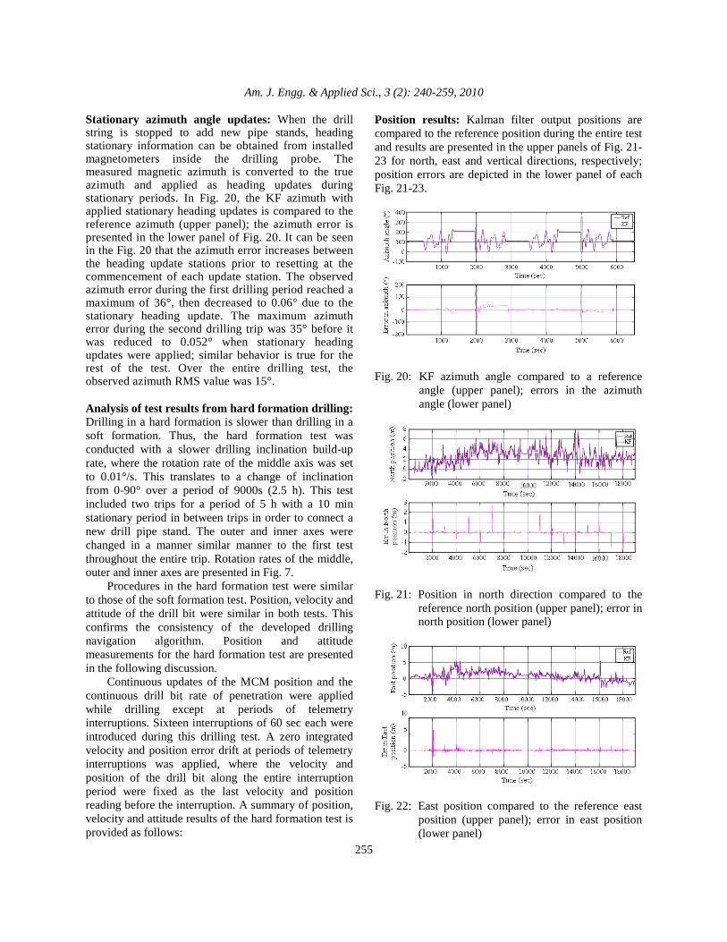
Stationary azimuth angle updates: When the drill string is stopped to add new pipe stands, heading stationary information can be obtained from installed magnetometers inside the drilling probe. The measured magnetic azimuth is converted to the true azimuth and applied as heading updates during stationary periods. In Fig. 20, the KF azimuth with applied stationary heading updates is compared to the reference azimuth (upper panel); the azimuth error is presented in the lower panel of Fig. 20. It can be seen in the Fig. 20 that the azimuth error increases between the heading update stations prior to resetting at the commencement of each update station. The observed azimuth error during the first drilling period reached a maximum of 36°, then decreased to 0.06° due to the stationary heading update. The maximum azimuth error during the second drilling trip was 35° before it was reduced to 0.052° when stationary heading updates were applied; similar behavior is true for the rest of the test. Over the entire drilling test, the observed azimuth RMS value was 15°. Analysis of test results from hard formation drilling: Drilling in a hard formation is slower than drilling in a soft formation. Thus, the hard formation test was conducted with a slower drilling inclination build-up rate, where the rotation rate of the middle axis was set to 0.01°/s. This translates to a change of inclination from 0-90° over a period of 9000s (2.5 h). This test included two trips for a period of 5 h with a 10 min stationary period in between trips in order to connect a new drill pipe stand. The outer and inner axes were changed in a manner similar manner to the first test throughout the entire trip. Rotation rates of the middle, outer and inner axes are presented in Fig. 7. Procedures in the hard formation test were similar to those of the soft formation test. Position, velocity and attitude of the drill bit were similar in both tests. This confirms the consistency of the developed drilling navigation algorithm. Position and attitude measurements for the hard formation test are presented in the following discussion. Continuous updates of the MCM position and the continuous drill bit rate of penetration were applied while drilling except at periods of telemetry interruptions. Sixteen interruptions of 60 sec each were introduced during this drilling test. A zero integrated velocity and position error drift at periods of telemetry interruptions was applied, where the velocity and position of the drill bit along the entire interruption period were fixed as the last velocity and position reading before the interruption. A summary of position, velocity and attitude results of the hard formation test is provided as follows:
Position results: Kalman filter output positions are compared to the reference position during the entire test and results are presented in the upper panels of Fig. 21-23 for north, east and vertical directions, respectively; position errors are depicted in the lower panel of each Fig. 21-23.
Fig. 20: KF azimuth angle compared to a reference
angle (upper panel); errors in the azimuth angle (lower panel)
Fig. 21: Position in north direction compared to the
reference north position (upper panel); error in north position (lower panel)
Fig. 22: East position compared to the reference east
position (upper panel); error in east position (lower panel)
Am. J. Engg. & Applied Sci., 3 (2): 240-259, 2010
256
Fig. 23: Altitude compared to the reference altitude
(upper panel); error in altitude (lower panel)
Fig. 24: Synthetic inclination angle compared to
reference and KF driven inclination angles (upper panel); error in synthetic pitch angle (lower panel)
The maximum observed position errors during telemetry interruption periods was 2.73, 6.32 and 5.02 m for north, east and vertical directions, respectively. RMS position errors over the entire drilling process were 0.18, 0.29 and 0.26 m along the north, east and vertical directions, respectively. Attitude results: Synthetic inclination and toolface angles were used to overcome accuracy deterioration of the KF drill bit inclination and toolface angles in vertical or near vertical directions. The advantages of this method are discussed later. Synthetic pitch angles used during this test were compared to reference and KF derived angles in the upper panel of Fig. 24. The lower panel of Fig. 25 depicts the error in the pitch angle-a RMS pitch error of 0.11° was observed. Synthetic toolface angles are presented in the upper panel of Fig. 25 where they are compared to reference and KF toolface angles; the observed synthetic toolface errors are shown in the lower panel of Fig. 25. The observed RMS toolface error was 0.30° during the entire drilling period.
Fig. 25: Synthetic toolface angle compared to reference
and KF driven toolface angles (upper panel); error in synthetic toolface angle (lower panel)
Fig. 26: KF azimuth compared to a reference azimuth
(upper panel); error in azimuth (lower panel) The KF azimuth is compared to the reference azimuth and presented in the upper panel of Fig. 26, while azimuth error is presented in the lower panel. Stationary heading updates were applied when drilling was stopped to add a new pipe stand. Drilling was stopped for 10 min after the first trip at time 9400 sec. Continuous MCM position and drill bit rate of penetration updates were available and utilized in the Kalman filter. The observed RMS azimuth error was 11° during drilling. The observed azimuth error during the first drilling period reached a maximum 28° then decreased to 0.6° due to the stationary heading update. The maximum azimuth error during the second drilling trip was 35.5°.
DISCUSSION The continuous surveying of a well trajectory while drilling is a highly desirable application in the oil and gas drilling industry. This was difficult to achieve due
Am. J. Engg. & Applied Sci., 3 (2): 240-259, 2010
257
to two limitations: The size of gyroscopes prevents their installation inside the drilling housing and the current directional drilling technology relies only on magnetometer and accelerometer measurements at stationary surveying stations. This study s describes the development of a continuous borehole surveying system based on a complete low cost MEMS INS package. A novel update scheme based on Kalman filtering was developed integrating INS measurements with external drilling parameter updates. The continuous drill bit rate of penetration and MCM position were applied as external measurement updates while drilling. Moreover, stationary updates of ZUPT, MCM position and a magnetometer heading were applied to the Kalman filter when drilling was stopped so a new drill pipe stand could be connected. Two experiments simulating the drilling through soft and hard for were conducted. The two tests differ in the build up rate of the inclination angle. The inclination build up rate was 0.1°/s while drilling in a soft formation and a slower rate of 0.01°/s while drilling in a hard formation. The first test extended for a period of approximately two h with an achieved position accuracy of 0.24, 0.72 and 0.36 m along the drill bit North, East and vertical directions, respectively. The second test was run for over 5 h and had a maximum position error of 0.25, 1.2 and 0.41 m in North, East and vertical directions, respectively. It should be noted that this particular analysis/results is valid only for the class of the utilized inertial hardware and the defined test parameters. More analysis is required for other inertial sensors and inclination build up rates in order to generalize the results. Limiting errors at telemetry interruption periods: A telemetry interruption is a period when a communication problem prevents transferring of the external measurements updates to the Kalman filter. The position components of error begin to grow if there is a telemetry interruption of the continuous drill bit rate of penetration and MCM position updates; these errors continue to grow until continuous updates become available again. To reduce position error growth, zero integrated velocity and position error drift at periods of telemetry interruption was proposed. In this technique, the velocity and position of the drill bit along the entire interruption period are fixed at the last velocity and position reading before the interruption. This significantly reduced the magnitude of errors during periods of telemetry interruption.
Synthetic attitude angles: Synthetic inclination and toolface angles based on accelerometer measurements were established in this study by making a use of the slow drilling operation. Improvements of 75 times for drill bit inclination angle and 30 times for toolface angle were achieved by utilizing the synthetic angles technique. The advantage of the synthetic inclination and toolface angles is their dependence only on accelerometer measurements. Accelerometer measurements are more stable and exhibit less error drift than gyroscope measurements.
CONCLUSION This study investigated the potential of low cost MEMS inertial sensors as a borehole surveying system for oil and gas directional drilling applications. Such a system can be miniaturized on the electronic chassis inside an MWD tool or inside an RSS electronic section. This study validated and qualified the MEMS INS for drilling applications where the hostile drilling environment is a limiting factor to most commercially available inertial navigation systems. A method utilizing a complete MEMS-based INS was employed to continuously survey a well trajectory while drilling. The MEMS sensor measurements were processed through Kalman filtering and unique external aiding measurements while drilling. The performance of the surveying technique was enhanced during periods of telemetry interruptions of continuous update measurements. This was achieved by employing the proposed zero integrated velocity and position error drift. Finally, the inclination and toolface accuracies of the drill bit were improved by using synthetic inclination and toolface angles based entirely on accelerometer measurements.
REFERENCES Berger, P.E. and R. Sele, 1998. Improving wellbore
position accuracy of horizontal wells by using a continuous inclinat measurement from a near bit inclination MWD sensor. Proceeding of the Society Petroleum Engineers International Conference on Horizontal Well Technology, Nov. 1-4, Calgary, Alberta, Canada, pp: 1-9. DOI: 10.2118/50378-MS
Bernstein, J., 2003. An overview of MEMS inertial sensing technology.
Binder, Y.I., I.M. Okon, T.V. Paderina and V.G. Rozentsvein, 2005. Problem of monitoring of arbitrary oriented trajectories of boreholes with small diameters by means of strapdown gyroscopic inclinometers and its solution methods. Proceeding of the Society of Petroleum Engineers, Western Regional Meeting, Mar. 30-Apr. 3, Irvine, California, USA., pp: 1-7. DOI: 10.2118/93874-MS
Bourgoyne, A.T., K.K. Millheim, M.E. Chenevert and F.S. Young, 1986. Applied Drilling Engineering. Society of Petroleum Engineers, Richardson TX, USA., ISBN: 9781555630010, pp: 510.
Crossbow, 2009. IMU300 6DOF inertial measurement unit data sheet.
Edmondson, J. and A. Chris, 2002. The application of rotary closed-loop drilling technology to meet the challenges of complex wellbore trajectories in the Janice field. Soc. Petroleum Drill. Complet., 17: 151-158. DOI: 10.2118/78809-PA
ElGizawy, M.L., 2009. Continuous measurement-while-drilling surveying system utilizing MEMS inertial sensors. A Dissertation for the Partial Fulfillment of Requirements for the Degree of Doctor of Philosophy Calgary, Department of Geomatics Engineering, Faculty of Graduate Studies, University of Calgary, Canada, pp: 1-224.
ElGizawy, M., A. Noureldin and N. El-Sheimy, 2006. Performance analysis of tactical grade inertial systems for Measurement-While-Drilling (MWD) process. Proceeding of the IEEE/ION Position Location and Navigation Symposium, Apr. 25-27, IEEE Xplore Press, Plans San Diego, CA, USA., pp: 16-22.
Estes, R.A. and D.M. Epplin, 2000. Development of a robust gyroscopic orientation tool for MWD operations. Proceeding of the Society of Petroleum Engineers Annual Technical Conference and Exhibition, Oct. 1-4, Dallas, TX, USA., pp: 1-13. DOI: 10.2118/63274-MS
Grindord S. and C. Wolf, 1983. Calculation of NMDC length required for various latitudes developed from field measurements of drill string magnetization. Proceeding of the in Society of Petroleum Engineers/International Association of Drilling Contractors Drilling Conference, Feb. 2023, New Orleans, LA, USA., pp: 1-8. DOI: 10.2118/11382-MS
Honeywell, 2009. HG1700 inertial measurement unit datasheet. http://www51.honeywell.com/aero/common/documents/myaerospacecatalog-documents/Missiles-Munitions/HG1700_Inertial_Measurement_Unit.pdf
Ideal Aerosmith, 2006. Model 2103HT three-axis positioning and rate table system. http://www.ideal-aerosmith.com/pdf/2103HT.pdf
Jekeli, C., 2000. Inertial Navigation Systems with Geodetic Applications. Walter de Gruyter, New York, USA., ISBN: 9783110159035, pp: 352.
Joshi S.D. and W. Ding, 1991. The Cost Benefits of Horizontal Drilling. American Gas Association Arlington, VA, USA.
Mohamed, A.H., 1999. Optimizing the estimation procedure in INS/GPS integration for kinematic applications. A dissertation for the partial fulfillment of requirements for the degree of Doctor of Philosophy Calgary, Department of Geomatics Engineering, Faculty of Graduate Studies, University of Calgary, Canada. http://dspace.ucalgary.ca/bitstream/1880/25197/1/38492Mohamed.pdf
Noureldin, A., 2002. New measurement-while-drilling surveying technique utilizing a set of fiber optic rotation sensors. A Dissertation for the Partial Fulfillment of Requirements for the Degree of Doctor of Philosophy, Department of Electrical and Computer Engineering, Faculty of Graduate Studies, University of Calgary, Calgary, Canada, pp: 1-289.
Ripka, P., 2001. Magnetic Sensors and Magnetometers. Artech House Inc., Norwood, MA., USA., ISBN: 10: 1580530575, pp: 516.
Taylor, H.L. and C.M. Mason, 1972. Systematic approach to well surveying calculations. SPE J., 12: 472-488. DOI: 10.2118/3362-PA
Thorogood, J.L. and D.R. Knott, 1990. Surveying techniques with a solid state magnetic multi-shot device. SPE Drill. Eng., 5: 209-214. DOI: 10.2118/19030-PA
Titterton, D.H. and J.L. Weston, 1997. Strapdown Inertial Navigation Technology. Peter Peregrinus Ltd., London, UK., ISBN: 10: 1563476932.
Am. J. Engg. & Applied Sci., 3 (2): 240-259, 2010
259
Weijermans, P., J. Ruszka, H. Jamshidian and M. Matheson, 2001. Drilling with rotary steerable system reduces wellbore tortuosity. Proceeding of the Society of Petroleum Engineers and International Association of Drilling Conference, Feb. 27-Mar. 1, Amsterdam, The Netherlands, pp: 1-10. DOI: 10.2118/67715-MS
Wolf, C.J.M. and J.P. De Wardt, 1981. Borehole position uncertainty-analysis of measuring methods and derivation of systematic error model. J. Petroleum Technol., 33: 2339-2350. DOI: 10.2118/9223-PA
Zijsling, D.H. and R.A. Wilson, 1989. Improved magnetic surveying techniques: Field experience. Proceeding of the in Society of Petroleum Engineers Offshore Conference, Sept. 5-8, Aberdeen, UK., pp: 1-18. DOI: 10.2118/19239-MS