SIEP: Well Engineers Notebook, Edition 2, January 2001 xii L – DIRECTIONAL DRILLING Clickable list (Use the hierarchical list under "Bookmarks" to access individual tables and/or sub-topics) Depth references L-1 Azimuth true, magnetic & grid L-4 Directional well plan equations L-5 Bottom hole assemblies L-6 The use of mud motors L-15 Surveys L-27 Equations L-29
Transcript
SIEP: Well Engineers Notebook, Edition 2, January 2001xii
L – DIRECTIONAL DRILLING
Clickable list(Use the hierarchical list under "Bookmarks" to access individual tables and/or sub-topics)
Depth references L-1
Azimuth true, magnetic & grid L-4
Directional well plan equations L-5
Bottom hole assemblies L-6
The use of mud motors L-15
Surveys L-27
Equations L-29
L–1SIEP: Well Engineers Notebook, Edition 2, January 2001
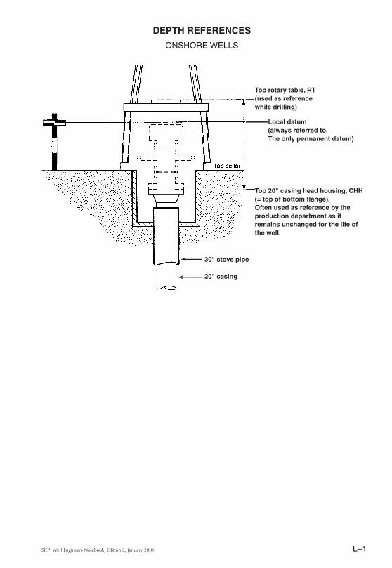
Top rotary table, RT(used as reference while drilling)
Local datum(always referred to.The only permanent datum)
Top 20" casing head housing, CHH(= top of bottom flange).Often used as reference by the production department as it remains unchanged for the life of the well.
DEPTH REFERENCES
ONSHORE WELLS
30" stove pipe
20" casing
SIEP: Well Engineers Notebook, Edition 2, January 2001L–2
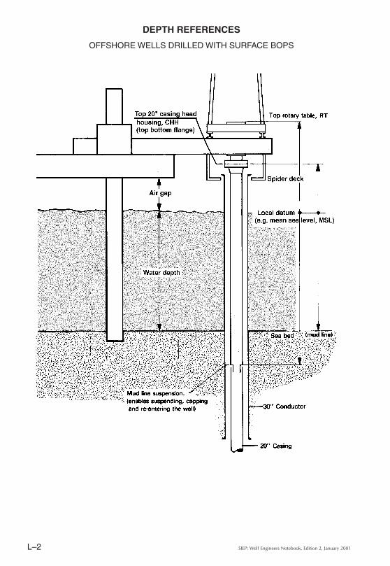
DEPTH REFERENCES
OFFSHORE WELLS DRILLED WITH SURFACE BOPS
L–3SIEP: Well Engineers Notebook, Edition 2, January 2001
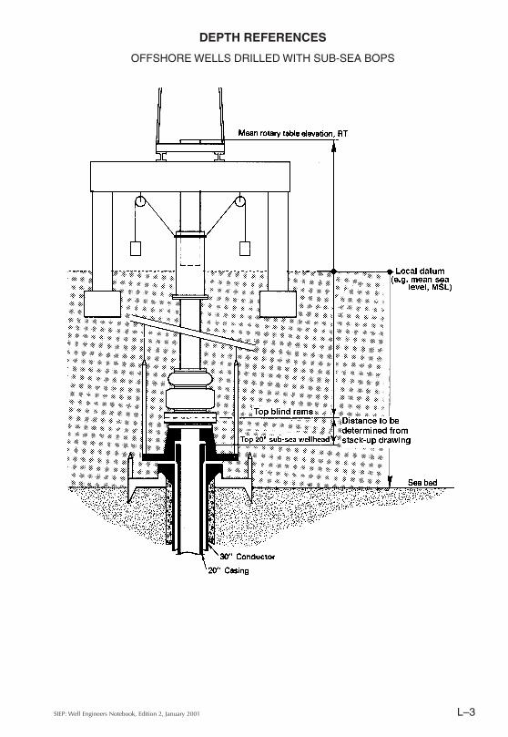
DEPTH REFERENCES
OFFSHORE WELLS DRILLED WITH SUB-SEA BOPS
SIEP: Well Engineers Notebook, Edition 2, January 2001L–4
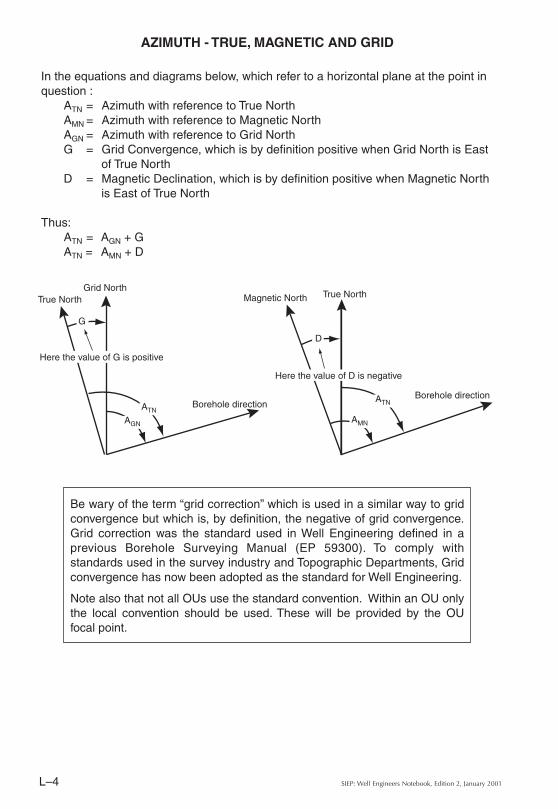
AZIMUTH - TRUE, MAGNETIC AND GRID
In the equations and diagrams below, which refer to a horizontal plane at the point in question :
ATN = Azimuth with reference to True NorthAMN = Azimuth with reference to Magnetic NorthAGN = Azimuth with reference to Grid NorthG = Grid Convergence, which is by definition positive when Grid North is East
of True NorthD = Magnetic Declination, which is by definition positive when Magnetic North
is East of True North
Thus:ATN = AGN + GATN = AMN + D
AGN
ATN
G
Grid North
Here the value of G is positive
True North
Borehole direction ATN
AMN
D
Magnetic North True North
Here the value of D is negative
Borehole direction
Be wary of the term “grid correction” which is used in a similar way to grid convergence but which is, by definition, the negative of grid convergence. Grid correction was the standard used in Well Engineering defined in a previous Borehole Surveying Manual (EP 59300). To comply with standards used in the survey industry and Topographic Departments, Grid convergence has now been adopted as the standard for Well Engineering.
Note also that not all OUs use the standard convention. Within an OU only the local convention should be used. These will be provided by the OU focal point.
L–5SIEP: Well Engineers Notebook, Edition 2, January 2001
D R
d
x
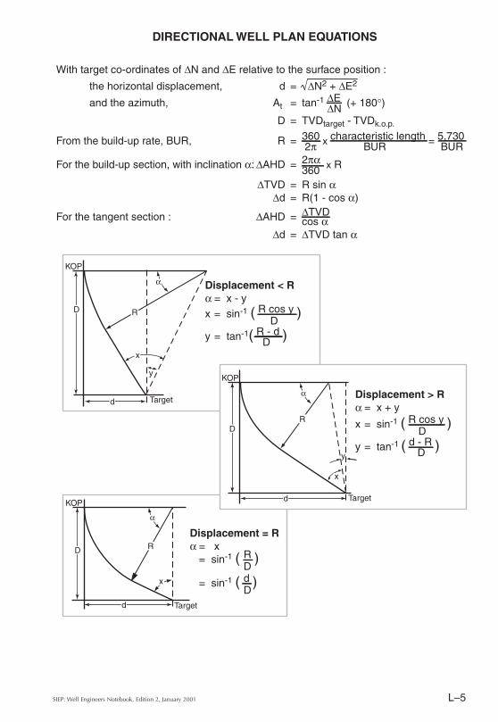
Displacement = Rα = x
= sin-1 ( R )D
= sin-1 ( d )D
DIRECTIONAL WELL PLAN EQUATIONS
With target co-ordinates of ∆N and ∆E relative to the surface position :
the horizontal displacement, d = ∆N2 + ∆E2
and the azimuth, At = tan-1 ∆E (+ 180°)∆ND = TVDtarget - TVDk.o.p.
From the build-up rate, BUR, R = 360 x characteristic length = 5,730 2π BUR BUR
For the build-up section, with inclination α: ∆AHD = 2πα x R 360∆TVD = R sin α
∆d = R(1 - cos α)
For the tangent section : ∆AHD = ∆TVDcos α
∆d = ∆TVD tan α
D R
d
x
y
DR
d
x
y
Displacement < Rα = x - yx = sin-1 ( R cos y )
Dy = tan-1( R - d )D
KOP
KOP
KOP
Target
Target
Targetα
α
α
Displacement > Rα = x + y
x = sin-1 ( R cos y )D
y = tan-1 ( d - R )D
SIEP: Well Engineers Notebook, Edition 2, January 2001L–6
BOTTOM HOLE ASSEMBLIES
FUNDAMENTAL PRINCIPLES
Fundamentals of BHA Design
In all cases, the minimum practical amount of BHA should be run. By running the minimum amount of BHA the torque and drag will be reduced, this in turn will reduce the fatigue generated in the drill string and thereby increase the life of the drill string.
All BHAs place a side force at the drill bit. This side force affects the path followed by the drill bit and the rate of angle change, (dog leg severity), in the well bore.
By planning to minimise the rate of angle change and by selecting the minimum number of tools having the correct material properties and assembling them in the correct order, good BHA design can delay fatigue damage and reduce the severity of drill string failure.
To achieve correct BHA design, it is necessary to understand the basic principles and the effect of selected physical properties of the BHA components.
Factors Affecting BHA Behaviour
The directional behaviour of a rotary BHA is affected in three different ways: by the mechanical characteristics of the BHA, by the drilling parameters applied to the BHA, and by the formation being drilled – over which we have no control.
Characteristics affecting BHA behaviour can be summarised as follows:
• The gauge and placement of stabilisers and other BHA components• The diameter, length and material of the BHA components• Bit type
Drilling parameters affecting BHA behaviour are:
• Weight on bit• Rotary speed• Circulation or flow rate
Directional Control Principles
There are three basic principles used to control well bore direction.
• The fulcrum principle – used to increase the well bore inclination. Inclination is the angle, expressed in degrees, between the path of the well bore and vertical.
• The stabilisation principle – used to hold both inclination and azimuth. Azimuth is the direction, expressed in degrees, between the path of the well bore and true North, or grid North if specified.
• The pendulum principle – used to drop inclination.
Note :
This and the following eight pages about BHAs have been taken from Shell Expro's “Drillstring Failure Prevention - BottomHole Assembly Design Guidelines” (WEIN 553), also available as SIEP Report EP 94-1103.
L–7SIEP: Well Engineers Notebook, Edition 2, January 2001
BOTTOM HOLE ASSEMBLIES
THE FULCRUM PRINCIPLE
A BHA with a full gauge near bit stabiliser, and between 90 ft and 120 ft of drill collars before the first string stabiliser (or no string stabiliser at all) will build inclination when weight on bit is applied .
The drill collars above the near bit stabiliser bend due to their own weight and also due to the weight on bit. The near bit stabiliser acts as the fulcrum point of a lever transmitting this bending moment down to the bit and pushing the bit upwards, thus building angle.
The following factors act on the build-up rate of this type of drilling assembly:
• Distance between the near bit stabiliser and the first string stabiliser.As this distance increases, the build-up rate also increases. However, once the distance between the first two stabilisers reaches 120 feet any further increase in length has little or no effect and might allow the drill collar to touch the side of the hole.
• The outside diameter of the drill collars.As the outside diameter increases, the collars become more rigid or "stiff' and the build-up rate decreases.
• Material of the drill collars.In the field, a choice of material is seldom available, so options are not normally possible. In a critical well this option should be considered at the planning phase.
• Bit type e.g. Tri-cone, PDC etc.The bit type has little effect on the build or drop rate, the exception being long gauge bits. The increase in gauge length decreases the build tendency. However the bit type does affect the "walk" or azimuth change, tricone bits tend to walk right whereas PDC bits exhibit little or no walk, but each bit does have its own characteristics.
• Weight on bit.An increase of the weight on bit tends to increase the bending force on the collars above the near bit stabiliser and hence the build-up rate.
• Rotary speedWith an increase in rotating speed the BHA becomes effectively more rigid and the build-up rate decreases.
• Flow rate.In soft formations, higher flow rates tend to decrease the building tendency due to the effect of the circulating fluid washing away the formation. This increases the hole size and decreases the support for the BHA.
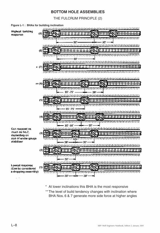
Figure L-1 shows several BHAs which will exhibit a build tendency. They are graduated from highest to lowest tendency to build angle, and are typical for a 121/4" hole.
SIEP: Well Engineers Notebook, Edition 2, January 2001L–8
BOTTOM HOLE ASSEMBLIES
THE FULCRUM PRINCIPLE (2)
* At lower inclinations this BHA is the most responsive**The level of build tendency changes with inclination where
BHA Nos. 6 & 7 generate more side force at higher angles
Figure L-1 : BHAs for building inclination
L–9SIEP: Well Engineers Notebook, Edition 2, January 2001
BOTTOM HOLE ASSEMBLIES
THE STABILISATION PRINCIPLE
By using three or more stabilisers with a short, large diameter drill collar between the near bit stabiliser and the first string stabiliser it is possible to reduce the transmission of bending moment to the bit, forcing it to follow a reasonably straight path. The BHAs that use this principle are called Packed Hole Assemblies and are used in vertical and deviated wells to maintain inclination and azimuth. Some bit walk may still be experienced when drilling with a packed hole assembly.
The following factors are of importance when designing stabilised BHAs:
• Stabiliser design.In large diameter holes (i.e. greater than 171/2") the use of straight bladed stabilisers is common. These are acceptable where the hole is vertical and the torque and drag when drilling is low. Due to its design, this style of stabiliser tends to dig into or "gouge" the well bore and will increase the torque and drag. For most hole sizes, stabilisers with 360° wall contact are available. These are of a long, wide, spiral blade design and provide full, effective support for the BHA without gouging the well bore.
• Near bit stabiliser.In all packed drilling assemblies, the near bit stabiliser must be full gauge. The stabiliser type and the area of blade contact with the hole wall require careful consideration to match formation and hole conditions. In areas of severe tendencies, tandem stabilisers can be used at the near bit position when stabilisers with long and wide blades are not available.
• Stabiliser spacing.The distance between the near bit stabiliser and the first string stabiliser, should be between 2 and 15 feet depending on hole size and hole condition. The shorter the spacing between the stabilisers the more rigid the assembly will be.
• First string stabiliser.The gauge of the first string stabiliser is of great importance and for most cases the stabiliser must be full gauge. (In areas where the assembly tends to drop, e.g. for deviated wells, an under gauge stabiliser is used to help maintain inclination.)
• Bit type.The two most commonly used bit types are tri-cone and PDC bits. The path drilled by a tri-cone bit will vary with applied weight on bit and rpm. PDC bits tend to drill straight holes regardless of weight on bit and RPM; long gauge PDC bits help to maintain a straight well path.
Where possible and depending on the formation, the use of PDC bits is recommended to help maintain a straight well path. With pendulum assemblies long gauge PDC bits can build angle as the long gauge acts as a near bit stabiliser.
• Rotary speed.
A higher rotating speed makes the BHA effectively stiffer and therefore less susceptible to deviate from the required well path. /....
SIEP: Well Engineers Notebook, Edition 2, January 2001L–10
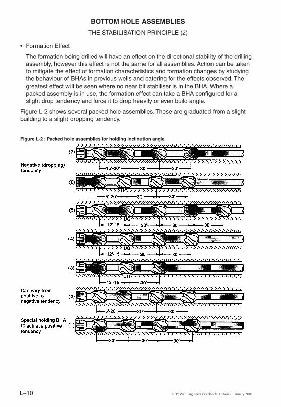
• Formation Effect
The formation being drilled will have an effect on the directional stability of the drilling assembly, however this effect is not the same for all assemblies. Action can be taken to mitigate the effect of formation characteristics and formation changes by studying the behaviour of BHAs in previous wells and catering for the effects observed. The greatest effect will be seen where no near bit stabiliser is in the BHA. Where a packed assembly is in use, the formation effect can take a BHA configured for a slight drop tendency and force it to drop heavily or even build angle.
Figure L-2 shows several packed hole assemblies. These are graduated from a slight building to a slight dropping tendency.
Figure L-2 : Packed hole assemblies for holding inclination angle
BOTTOM HOLE ASSEMBLIES
THE STABILISATION PRINCIPLE (2)
L–11SIEP: Well Engineers Notebook, Edition 2, January 2001
BOTTOM HOLE ASSEMBLIES
THE PENDULUM PRINCIPLE
The pendulum principle was originally used to drill vertical wells with slick (non stabilised) BHAs. It was modified to incorporate stabilisers and is still in use today to reduce inclination. The principle uses the weight of the BHA hanging below the tangent point to produce, via gravity, a force that pushes the bit to the low side of the hole. The effect of the pendulum varies with the length of the BHA below the tangent point.
The fundamental pendulum assembly increases the restoring force by increasing the pendulum length with a stabiliser in the proper position. The following are important factors to be considered in the design of pendulum drilling assemblies :
• Near bit stabiliser gauge.All pendulum assemblies use either an under-gauge near bit stabiliser or omit the near bit stabiliser completely.
• Stabiliser spacingThe distance between the bit and the first string stabiliser controls the weight of the hanging portion of the BHA and therefore the pendulum force. If the first string stabiliser is placed too far away from the bit the tangent point will fall between the stabiliser and the bit, i.e. wall contact will take place, thereby reducing the effectiveness of the pendulum.
• Outside diameter of the drill collars.
Drill collar stiffness increases with the fourth power of the outside diameter. Stiffer drill collars will place the tangent point farther away from the bit and also increase the pendulum force. The weight per foot of the drill collars to be proportional to the second power of the outside diameter, i.e., heavier drill collars will produce a larger pendulum force.In summary: For the portion of pendulum BHA below the tangent point or first drill string stabiliser, it is desirable to run drill collars with the largest possible outside diameter. BUT potential problems associated with fishing the drill collars must be considered in the design stage.
• Bit type.To allow the pendulum force to work the bit must be free and unrestricted. Field experience has shown that tri-cone bits and short gauge, flat face PDC bits are the most effective with pendulum drilling assemblies.
• Weight on bit.
The higher the weight on bit, the more the assembly will bend. This can move the tangent point nearer to the bit and hence is detrimental to the effectiveness of the assembly. Furthermore, the side force at the bit, produced by the weight on bit, acts against the pendulum force. Weight on bit as low as possible is desirable for a pendulum assembly. /....
SIEP: Well Engineers Notebook, Edition 2, January 2001L–12
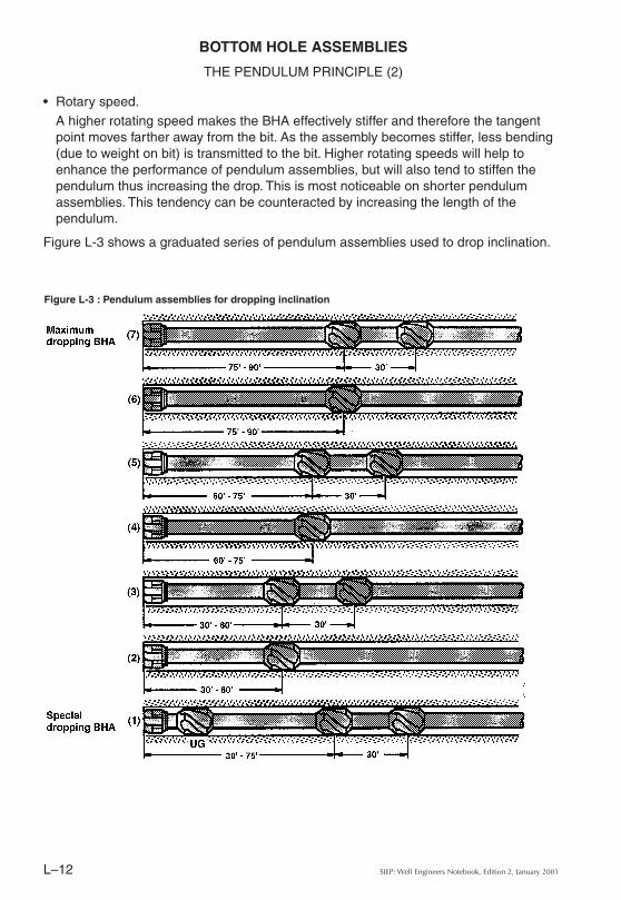
• Rotary speed.A higher rotating speed makes the BHA effectively stiffer and therefore the tangent point moves farther away from the bit. As the assembly becomes stiffer, less bending (due to weight on bit) is transmitted to the bit. Higher rotating speeds will help to enhance the performance of pendulum assemblies, but will also tend to stiffen the pendulum thus increasing the drop. This is most noticeable on shorter pendulum assemblies. This tendency can be counteracted by increasing the length of the pendulum.
Figure L-3 shows a graduated series of pendulum assemblies used to drop inclination.
Figure L-3 : Pendulum assemblies for dropping inclination
BOTTOM HOLE ASSEMBLIES
THE PENDULUM PRINCIPLE (2)
L–13SIEP: Well Engineers Notebook, Edition 2, January 2001
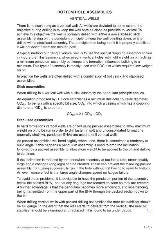
There is no such thing as a vertical well. All wells are deviated to some extent, the objective during drilling is to keep the well bore as close as possible to vertical. To achieve this objective the well is normally drilled with either a non stabilised slick assembly relying on the pendulum principle to keep the well pointing down, or it is drilled with a stabilised assembly. The principle then being that if it is properly stabilised it will not deviate from the desired path.
A typical method of drilling a vertical well is to use the special dropping assembly shown in Figure L-3. This assembly, when used in vertical holes with light weight on bit, acts as a minimum pendulum assembly but keeps any formation influenced building to a minimum. This type of assembly is mostly used with PDC bits which required low weight on bit.
In practice the wells are often drilled with a combination of both slick and stabilised assemblies.
Slick assemblies
When drilling in a vertical well with a slick assembly the pendulum principle applies.
An equation proposed by R. Hoch establishes a minimum drill collar outside diameter, ODdc, to be run with a specific bit size, ODb, into which a casing which has a coupling diameter of ODcc is to be run.
ODdc = 2 x ODcc - ODb
Stabilised assemblies
In hard formations vertical wells are drilled using packed assemblies to allow maximum weight on bit to be run in order to drill faster. In soft and unconsolidated formations (normally shallow), pendulum BHAs are used to drill vertical wells.
As packed assemblies will bend slightly when used, there is sometimes a tendency to build angle. If this happens a pendulum assembly is used to drop the inclination, followed by a packed assembly to allow more weight to be applied to the bit and drilling to continue.
If the inclination is reduced by the pendulum assembly at too fast a rate, unacceptably large angle changes (dog-legs) can be created. These can prevent the following packed assembly from being successfully run in the hole without first having to ream to bottom. An even worse effect is that large angle changes speed up fatigue failure.
To avoid these problems, it is advisable to have the pendulum portion of the assembly below the packed BHA, so that any dog-legs are reamed as soon as they are created. A further advantage is that the pendulum becomes more efficient due to less bending being transmitted from the upper part of the BHA through the packed section down to the bit.
When drilling vertical wells with packed drilling assemblies the near bit stabiliser should be full gauge. In the event that the well starts to deviate from the vertical, the near bit stabiliser should be examined and replaced if it is found to be under gauge. /....
BOTTOM HOLE ASSEMBLIES
VERTICAL WELLS
SIEP: Well Engineers Notebook, Edition 2, January 2001L–14
If the near bit stabiliser is full gauge, the width and length of the stabiliser blades should be checked, i.e. not too narrow or too short. If they are found to be acceptable then consideration should be given to either using a near bit stabiliser with wider and longer blades or by using tandem stabilisers in the near bit position.
Alternatively a "Big Bear" near bit stabiliser can be used. These are stabilisers of exceptional blade length, normally in the order of twice the blade length of that seen on a standard stabiliser (3 feet). They are therefore suitable to replace a tandem near bit stabiliser.
When applying any of these latter solutions, exceptional precautions have to be taken when running in hole. Due to the extreme stiffness of the near bit section great care should be taken not to mechanically stick the assembly, especially the first time such an assembly is run in the hole.
BOTTOM HOLE ASSEMBLIES
VERTICAL WELLS (2)
L–15SIEP: Well Engineers Notebook, Edition 2, January 2001
Picking up a mud motor
Motors are generally supplied with a lifting or handling sub for transporting them to and from the rig floor. These lifting subs are normally rated to lift the motors only and should not be used for heavier lifts such as the complete drilling assembly.
Surface checks prior to running a mud motor in hole
Using the lifting sub, pick up the motor and set into the slips at the rotary table. Install the drill collar safety clamp below the dump valve ports, unlatch the elevators and remove the lifting sub. Check that the dump valve is free to move by pressing downwards with a hammer handle on the upper face of the piston, the piston should travel down two to three inches and return to the open position when the downwards pressure is released.
To check that the dump valve is not leaking, press on the piston again and, whilst holding the valve down in the closed position, fill the valve cavity with water. Release the downward pressure, the piston should return to the open position and the water in the valve cavity will drain out through the ports.
Using a cross over sub, connect the kelly or top drive to the motor. Remove the safety clamp and pick up the motor until the bit sub is above the rotary table. Measure the gap between the bit sub and the bearing housing. Set the motor down, making sure to protect the box shoulder by landing the bit box on wood or on a rubber mat over the rotary table. Measure the gap between the bit sub and the bearing housing again. Check that the measured play is within the specified tolerances for the motor.
Lower the motor so that the dump valve ports are below the rotary table. Start the pumps and, once there is no more flow through the ports, pick up the motor and observe the bit sub rotating. There should be flow between the bearing housing and the bit box. Lower the motor until the dump valve ports are below the rotary table and shut down the pumps.
Pick up the motor and attach the bit using a bit breaker while holding the bit sub with a tong.
Tripping into the hole
Run the tool in the hole carefully. Care should be taken not to run the motor into bridges, ledges or the bottom of the hole. Work through tight spots with the pump on and slow rotation. Should difficulty be experienced when reaming through tight spots care should be taken not to side-track the well through the application of high weight on bit or high rotary speeds.
When running in the hole if the drill string does not self fill, due to the properties of the drilling fluid preventing it from entering the drill string via the dump valve, periodically break circulation to fill the drill string. /....
THE USE OF MUD MOTORS
GENERAL OPERATING PROCEDURES
Note :These mud motor operating procedures have been taken from Shell Expro's “Drillstring Failure Prevention - BottomHole Assembly Design Guidelines” (WEIN 553), also available as SIEP Report EP 94-1103.
SIEP: Well Engineers Notebook, Edition 2, January 2001L–16
In hot wells, above 250°F bottom hole temperature, break circulation periodically while running in the hole to cool down the motor.
When using a PDC bit, avoid circulating inside the casing to prevent damage to the casing and to the bit.
Drilling
To commence drilling, with the bit two or three feet off bottom, start the pumps and slowly increase the flow rate to that required for drilling. Do not exceed the maximum flow rate for the motor. Once the pressure has stabilised make a note of the flow rate and the pump pressure, gently lower the bit to bottom and slowly increase the weight on bit, as the weight on bit increases there will be a corresponding increase in pump pressure.
For each motor there is a specified maximum differential pressure, the difference between the on bottom and off bottom pressure, this maximum should not be exceeded. It is good drilling practice to keep this differential pressure and the flow rate constant.
Tripping out
The procedures for tripping out of the hole are the same as when a rotary drilling assembly is in use.
However, once out of the hole, the bearing clearance should be checked in the same manner as it is checked prior to running in the hole. The motor should also be flushed with fresh water, and the bit removed. The same lift sub used to pick up the motor prior to running in the hole should be screwed in to the top of the motor and made up to a reduced torque valve. The lift sub should not be screwed in hand tight for lifting operations.
THE USE OF MUD MOTORS
GENERAL OPERATING PROCEDURES (2)
L–17SIEP: Well Engineers Notebook, Edition 2, January 2001
THE USE OF MUD MOTORS
STEERING BY MEANS OF “MAGNETIC TOOLFACE”
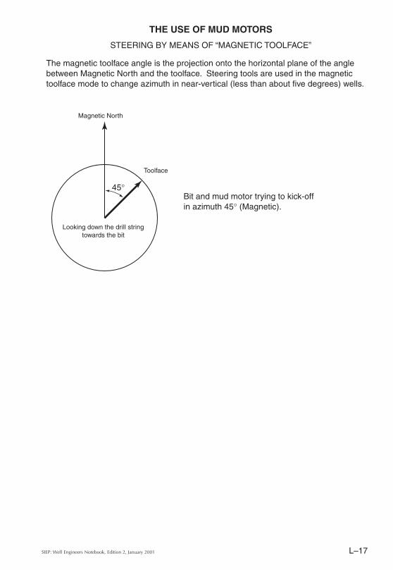
The magnetic toolface angle is the projection onto the horizontal plane of the angle between Magnetic North and the toolface. Steering tools are used in the magnetic toolface mode to change azimuth in near-vertical (less than about five degrees) wells.
45°Bit and mud motor trying to kick-off in azimuth 45° (Magnetic).
Toolface
Magnetic North
Looking down the drill string towards the bit
SIEP: Well Engineers Notebook, Edition 2, January 2001L–18
THE USE OF MUD MOTORS
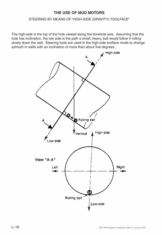
STEERING BY MEANS OF “HIGH-SIDE (GRAVITY) TOOLFACE”
The high-side is the top of the hole viewed along the borehole axis. Assuming that the hole has inclination, the low side is the path a small, heavy, ball would follow if rolling slowly down the well. Steering tools are used in the high-side toolface mode to change azimuth in wells with an inclination of more than about five degrees..
L–19SIEP: Well Engineers Notebook, Edition 2, January 2001
THE USE OF MUD MOTORS
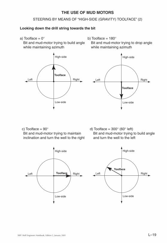
STEERING BY MEANS OF “HIGH-SIDE (GRAVITY) TOOLFACE” (2)
High-side
Right
Low-side
Left
High-side
Right
Low-side
Left
High-side
Right
Low-side
Left
High-side
Right
Low-side
Left
a) Toolface = 0°Bit and mud-motor trying to build angle while maintaining azimuth
d) Toolface = 300° (60° left)Bit and mud-motor trying to build angle and turn the well to the left
c) Toolface = 90°Bit and mud-motor trying to maintain inclination and turn the well to the right
b) Toolface = 180°Bit and mud-motor trying to drop angle while maintaining azimuth
Looking down the drill string towards the bit
ToolfaceToolface
Toolface
Toolface
SIEP: Well Engineers Notebook, Edition 2, January 2001L–20
THE USE OF MUD MOTORS
REACTIVE TORQUE
A clockwise rotating downhole motor applies right-hand torque to the bit. There is therefore an equal and opposite torque applied by the bit to the stator housing, and thence to the string. Called 'reactive torque', this can easily be controlled by the operator, by controlling weight on bit. During directional drilling, this reactive torque must be taken into consideration, because it tends to turn the drill string to the left. The actual angle of twist created at the bottom of the string by reactive torque is governed by:• The magnitude of the torque• The length of drill pipe• The torsional elasticity of the drill pipe• The length and torsional elasticity of the HWDP and BHA.
The HWDP and BHA are both much shorter and much stiffer than the drill pipe and can therefore be neglected when estimating the BHA rotation due to reactive torque, given the accuracy to which the estimate is required.
This BHA rotation in a drill string with a mud motor may be estimated as follows:• Measure the standpipe pressure with the bit on bottom, when flow rate and weight on
bit are adjusted to drilling conditions.• Measure the standpipe pressure when the bit is lifted off bottom with the flow rate
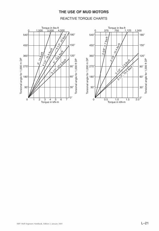
being kept constant.• Calculate difference in standpipe pressure.• If a diamond bit is in use, reduce the above value by the pressure drop at the bit.• Read the reactive torque values for the calculated differential pressure from tables.• Obtain the corresponding torsion angle per unit length for the drill pipe in use from the
graphs on the facing page.
After orientation by single shot measurement, the string has to be aligned to produce the required bore hole direction. To do so, the above calculated reactive torque angle is considered as a right-hand angle in addition to the direction change. Having applied the accumulated angle of the string with the rotary table, the string should be raised and lowered several times over a 30 ft interval.
Once a few feet/metres of hole have been made with the new settings, the result will be checked and the drill pipe alignment adjusted in light of the actual results. This is the reason why the preliminary estimate is only required to an "order of magnitude" accuracy.
L–21SIEP: Well Engineers Notebook, Edition 2, January 2001
THE USE OF MUD MOTORS
REACTIVE TORQUE CHARTS
0 1,500 3,000 4,500
180°
150°
120°
90°
60°
30°
0°
540°
450°
360°
270°
180°
90°
0 1 2 3 4 5 6 7Torque in kN-m
Torque in lbs-ft
Tors
iona
l ang
le fo
r 1,
000
m D
P
Tors
iona
l ang
le fo
r 1,
000
ft D
P
4-1/
2", 1
6.6
lbs/
ft5"
, 19.
5 lb
s/ft
4-1/
2", 2
0 lb
s/ft
4", 1
4 lb
s/ft
5-1/
2", 2
0.9
lbs/ft
0 375 750 1,125
180°
150°
120°
90°
60°
30°
0°
540°
450°
360°
270°
180°
90°
0 0.5 1.0 1.5 2.0Torque in kN-m
Torque in lbs-ft
Tors
iona
l ang
le fo
r 1,
000
m D
P
Tors
iona
l ang
le fo
r 1,
000
ft D
P
1,500
2-3/
8", 6
.7 lb
s/ft
2-7/
8", 1
0.4
lbs/
ft3-
1/2"
, 13.
3 lbs
/ft
3-1/2
", 15
.5 lbs
/ft
SIEP: Well Engineers Notebook, Edition 2, January 2001L–22
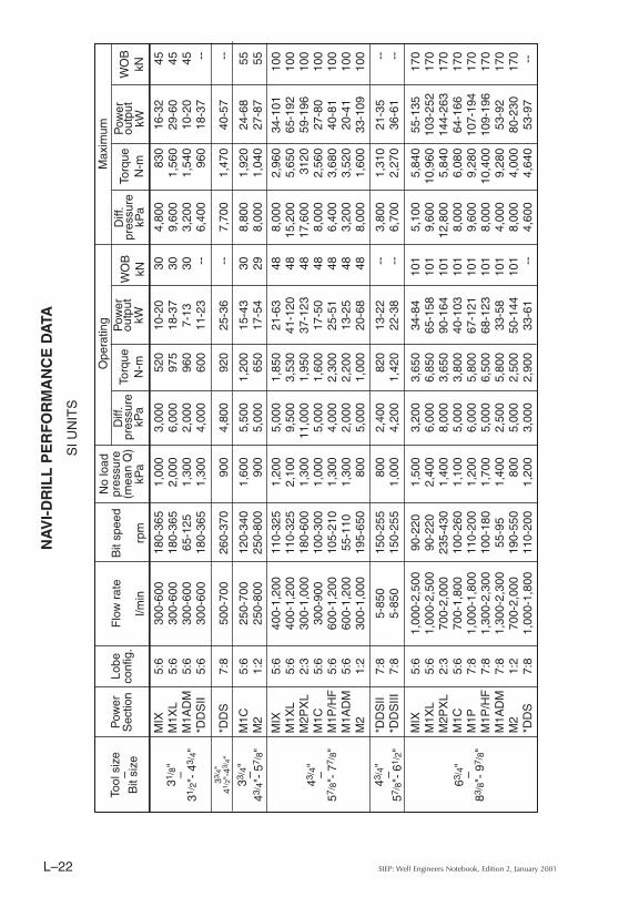
NA
VI-
DR
ILL
PE
RF
OR
MA
NC
E D
ATA
MIX
5:6
300-
600
180-
365
1,00
03,
000
520
10-2
030
4,80
083
016
-32
45M
1XL
5:6
300-
600
180-
365
2,00
06,
000
975
18-3
730
9,60
01,
560
29-6
045
M1A
DM
5:6
300-
600
65-1
251,
300
2,00
096
07-
1330
3,20
01,
540
10-2
045
*DD
SII
5:6
300-
600
180-
365
1,30
04,
000
600
11-2
3--
6,40
096
018
-37
--
*DD
S7:
850
0-70
026
0-37
090
04,
800
920
25-3
6--
7,70
01,
470
40-5
7--
M1C
5:6
250-
700
120-
340
1,60
05,
500
1,20
015
-43
308,
800
1,92
024
-68
55M
21:
225
0-80
025
0-80
090
05,
000
650
17-5
429
8,00
01,
040
27-8
755
MIX
5:6
400-
1,20
011
0-32
51,
200
5,00
01,
850
21-6
348
8,00
02,
960
34-1
0110
0M
1XL
5:6
400-
1,20
011
0-32
52,
100
9,50
03,
530
41-1
2048
15,2
005,
650
65-1
9210
0M
2PX
L2:
330
0-1,
000
180-
600
1,30
011
,000
1,95
037
-123
4817
,600
3120
59-1
9610
0M
1C5:
630
0-90
010
0-30
01,
000
5,00
01,
600
17-5
048
8,00
02,
560
27-8
010
0M
1P/H
F5:
660
0-1,
200
105-
210
1,30
04,
000
2,30
025
-51
486,
400
3,68
040
-81
100
M1A
DM
5:6
600-
1,20
055
-110
1,30
02,
000
2,20
013
-25
483,
200
3,52
020
-41
100
M2
1:2
300-
1,00
019
5-65
080
05,
000
1,00
020
-68
488,
000
1,60
033
-109
100
*DD
SII
7:8
5-85
015
0-25
580
02,
400
820
13-2
2--
3,80
01,
310
21-3
5--
*DD
SIII
7:8
5-85
015
0-25
51,
000
4,20
01,
420
22-3
8--
6,70
02,
270
36-6
1--
MIX
5:6
1,00
0-2,
500
90-2
201,
500
3,20
03,
650
34-8
410
15,
100
5,84
055
-135
170
M1X
L5:
61,
000-
2,50
090
-220
2,40
06,
000
6,85
065
-158
101
9,60
010
,960
103-
252
170
M2P
XL
2:3
700-
2,00
023
5-43
01,
400
8,00
03,
650
90-1
6410
112
,800
5,84
014
4-26
317
0M
1C5:
670
0-1,
800
100-
260
1,10
05,
000
3,80
040
-103
101
8,00
06,
080
64-1
6617
0M
1P7:
81,
000-
1,80
011
0-20
01,
200
6,00
05,
800
67-1
2110
19,
600
9,28
010
7-19
417
0M
1P/H
F7:
81,
300-
2,30
010
0-18
01,
700
5,00
06,
500
68-1
2310
18,
000
10,4
0010
9-19
617
0M
1AD
M7:
81,
300-
2,30
055
-95
1,40
02,
500
5,80
033
-58
101
4,00
09,
280
53-9
217
0M
21:
270
0-2,
000
190-
550
800
5,00
02,
500
50-1
4410
18,
000
4,00
080
-230
170
*DD
S7:
81,
000-
1,80
011
0-20
01,
200
3,00
02,
900
33-6
1--
4,60
04,
640
53-9
7--
Pow
erS
ectio
nLo
beco
nfig
.F
low
rat
e
l/min
Bit
spee
d
rpm
No
load
pres
sure
(mea
n Q
)kP
a
Ope
ratin
gD
iff.
pres
sure
kPa
Torq
ueN
-m
Pow
erou
tput
kWW
OB
kNW
OB
kN
Diff
.pr
essu
rekP
aTo
rque
N-m
Pow
erou
tput
kW
Tool
siz
e–
Bit
size
31/ 8
"–
31/ 2
"- 4
3 /4"
33/ 4
"41
/ 2"-
43 /4 "
33/ 4
"–
43/ 4
"- 5
7 /8"
43/ 4
"–
57/ 8
"- 7
7 /8"
43/ 4
"–
57/ 8
"- 6
1 /2"
63/ 4
"–
83/ 8
"- 9
7 /8"
Max
imum
SI U
NIT
S
L–23SIEP: Well Engineers Notebook, Edition 2, January 2001
M1C
5:6
1,20
0-2,
600
85-1
901,
300
4,00
06,
100
54-1
2115
56,
400
9,76
087
-194
300
M1P
7:8
1,50
0-2,
500
90-1
5090
06,
000
10,5
0099
-165
155
9,60
016
,800
158-
264
300
M1P
/HF
9:10
2,00
0-3,
400
90-1
502,
000
5,00
011
,500
108-
181
155
8,00
018
,400
173-
289
300
M1A
DM
7:8
2,00
0-3,
400
50-8
01,
500
2,50
010
,100
53-8
515
54,
000
16,1
6085
-135
300
M2
1:2
900-
2,60
015
5-45
080
04,
000
3,25
053
-153
155
6,40
05,
200
84-2
4530
0
M1X
L5:
62,
000-
4,00
080
-165
1,80
06,
000
14,6
0012
2-25
221
49,
600
23,3
6019
6-40
440
0M
1C5:
61,
500-
2,80
010
0-19
01,
000
5,50
09,
300
97-1
8521
48,
800
14,8
8015
6-29
640
0M
1P7:
81,
800-
3,00
080
-130
700
6,00
015
,000
126-
204
214
9,60
024
,000
201-
327
400
M1P
/HF
9:10
2,50
0-4,
200
80-1
301,
600
5,00
017
,000
142-
231
214
8,00
027
,200
228-
370
400
M1A
DM
7:8
2,50
0-4,
200
40-7
01,
300
2,50
015
,000
63-1
1021
44,
000
24,0
0010
1-17
640
0M
21:
21,
500-
3,00
020
0-40
090
06,
000
6,45
013
5-27
021
49,
600
10,3
2021
6-43
240
0
M1C
5:6
2,00
0-4,
300
80-1
701,
600
4,50
013
,200
111-
235
227
7,20
021
,120
177-
376
500
M1P
9:10
3,00
0-4,
800
70-1
101,
600
5,00
024
,000
176-
276
227
8,00
038
,400
281-
442
500
M2
1:2
2,00
0-4,
300
155-
330
800
4,00
07,
500
122-
259
227
6,40
012
,000
195-
415
500
Pow
erS
ectio
nLo
beco
nfig
.F
low
rat
e
l/min
Bit
spee
d
rpm
No
load
pres
sure
(mea
n Q
)kP
a
Ope
ratin
gD
iff.
pres
sure
kPa
Torq
ueN
-m
Pow
erou
tput
kWW
OB
kNW
OB
kN
Diff
.pr
essu
rekP
aTo
rque
N-m
Pow
erou
tput
kW
Tool
siz
e–
Bit
size
8" –91
/ 2"-
121 /
4"
91/ 2
"–
121 /
4"-
171 /
2"
111 /
4"–
16"-
26"
Max
imum
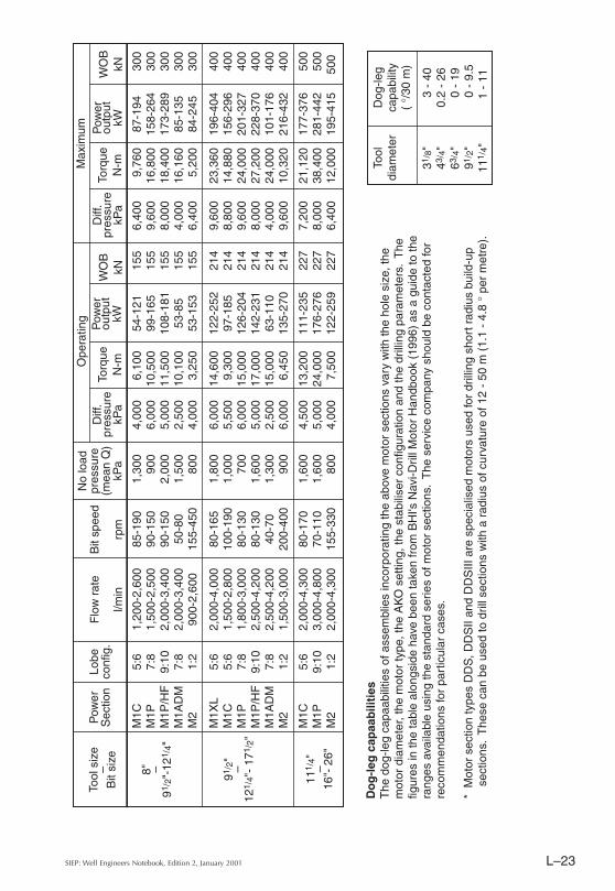
Do
g-l
eg c
apaa
bili
ties
The
dog
-leg
capa
abili
ties
of a
ssem
blie
s in
corp
orat
ing
the
abov
e m
otor
sec
tions
var
y w
ith th
e ho
le s
ize,
the
mot
or d
iam
eter
, the
mot
or ty
pe, t
he A
KO
set
ting,
the
stab
ilise
r co
nfig
urat
ion
and
the
drill
ing
para
met
ers.
The
fig
ures
in th
e ta
ble
alon
gsid
e ha
ve b
een
take
n fr
om B
HI's
Nav
i-Dril
l Mot
or H
andb
ook
(199
6) a
s a
guid
e to
the
rang
es a
vaila
ble
usin
g th
e st
anda
rd s
erie
s of
mot
or s
ectio
ns.
The
ser
vice
com
pany
sho
uld
be c
onta
cted
for
reco
mm
enda
tions
for
part
icul
ar c
ases
.
* M
otor
sec
tion
type
s D
DS
, DD
SII
and
DD
SIII
are
spe
cial
ised
mot
ors
used
for
drill
ing
shor
t rad
ius
build
-up
sect
ions
. T
hese
can
be
used
to d
rill s
ectio
ns w
ith a
rad
ius
of c
urva
ture
of 1
2 -
50 m
(1.
1 -
4.8
° pe
r m
etre
).
Tool
Dog
-leg
diam
eter
capa
bilit
y(
°/30
m)
31/ 8
"
3 -
4043
/ 4"
0.2
- 26
63/ 4
"
0 -
1991
/ 2"
0
- 9
.511
1 /4"
1
- 11
SIEP: Well Engineers Notebook, Edition 2, January 2001L–24
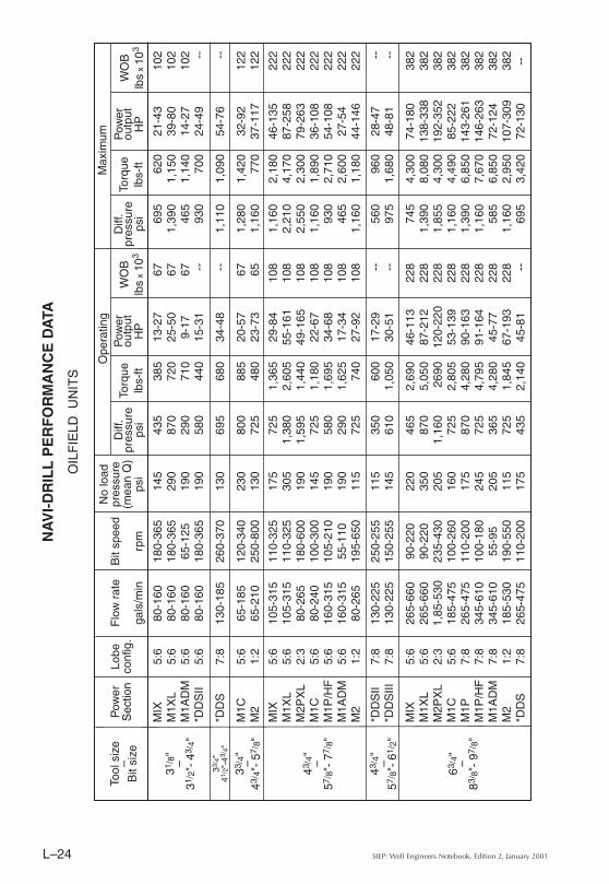
NA
VI-
DR
ILL
PE
RF
OR
MA
NC
E D
ATA
MIX
5:6
80-1
6018
0-36
514
543
538
513
-27
6769
562
021
-43
102
M1X
L5:
680
-160
180-
365
290
870
720
25-5
067
1,39
01,
150
39-8
010
2M
1AD
M5:
680
-160
65-1
2519
029
071
09-
1767
465
1,14
014
-27
102
*DD
SII
5:6
80-1
6018
0-36
519
058
044
015
-31
--93
070
024
-49
--
*DD
S7:
813
0-18
526
0-37
013
069
568
034
-48
--1,
110
1,09
054
-76
--
M1C
5:6
65-1
8512
0-34
023
080
088
520
-57
671,
280
1,42
032
-92
122
M2
1:2
65-2
1025
0-80
013
072
548
023
-73
651,
160
770
37-1
1712
2
MIX
5:6
105-
315
110-
325
175
725
1,36
529
-84
108
1,16
02,
180
46-1
3522
2M
1XL
5:6
105-
315
110-
325
305
1,38
02,
605
55-1
6110
82,
210
4,17
087
-258
222
M2P
XL
2:3
80-2
6518
0-60
019
01,
595
1,44
049
-165
108
2,55
02,
300
79-2
6322
2M
1C5:
680
-240
100-
300
145
725
1,18
022
-67
108
1,16
01,
890
36-1
0822
2M
1P/H
F5:
616
0-31
510
5-21
019
058
01,
695
34-6
810
893
02,
710
54-1
0822
2M
1AD
M5:
616
0-31
555
-110
190
290
1,62
517
-34
108
465
2,60
027
-54
222
M2
1:2
80-2
6519
5-65
011
572
574
027
-92
108
1,16
01,
180
44-1
4622
2
*DD
SII
7:8
130-
225
250-
255
115
350
600
17-2
9--
560
960
28-4
7--
*DD
SIII
7:8
130-
225
150-
255
145
610
1,05
030
-51
--97
51,
680
48-8
1--
MIX
5:6
265-
660
90-2
2022
046
52,
690
46-1
1322
874
54,
300
74-1
8038
2M
1XL
5:6
265-
660
90-2
2035
087
05,
050
87-2
1222
81,
390
8,08
013
8-33
838
2M
2PX
L2:
31,
85-5
3023
5-43
020
51,
160
2690
120-
220
228
1,85
54,
300
192-
352
382
M1C
5:6
185-
475
100-
260
160
725
2,80
553
-139
228
1,16
04,
490
85-2
2238
2M
1P7:
826
5-47
511
0-20
017
587
04,
280
90-1
6322
81,
390
6,85
014
3-26
138
2M
1P/H
F7:
834
5-61
010
0-18
024
572
54,
795
91-1
6422
81,
160
7,67
014
6-26
338
2M
1AD
M7:
834
5-61
055
-95
205
365
4,28
045
-77
228
585
6,85
072
-124
382
M2
1:2
185-
530
190-
550
115
725
1,84
567
-193
228
1,16
02,
950
107-
309
382
*DD
S7:
826
5-47
511
0-20
017
543
52,
140
45-8
1--
695
3,42
072
-130
--
Pow
erS
ectio
nLo
beco
nfig
.F
low
rat
e
gals
/min
Bit
spee
d
rpm
No
load
pres
sure
(mea
n Q
)ps
i
Ope
ratin
gD
iff.
pres
sure
psi
Torq
uelb
s-ft
Pow
erou
tput
HP
WO
Blb
s x
103
WO
Blb
s x
103
Diff
.pr
essu
reps
iTo
rque
lbs-
ft
Pow
erou
tput
HP
Tool
siz
e–
Bit
size
31/ 8
"–
31/ 2
"- 4
3 /4"
33/ 4
"41
/ 2"-
43 /4 "
33/ 4
"–
43/ 4
"- 5
7 /8"
43/ 4
"–
57/ 8
"- 7
7 /8"
43/ 4
"–
57/ 8
"- 6
1 /2"
63/ 4
"–
83/ 8
"- 9
7 /8"
Max
imum
OIL
FIE
LD U
NIT
S
L–25SIEP: Well Engineers Notebook, Edition 2, January 2001
M1C
5:6
315-
685
85-1
9019
058
04,
500
73-1
6334
893
07,
200
117-
260
674
M1P
7:8
395-
660
90-1
5013
087
07,
745
133-
221
348
1,39
012
,390
212-
354
674
M1P
/HF
9:10
530-
900
90-1
5029
072
58,
480
145-
242
348
1,16
013
,570
233-
388
674
M1A
DM
7:8
530-
900
50-8
022
036
57,
450
71-1
1334
858
511
,920
113-
182
674
M2
1:2
240-
685
155-
450
115
580
2,39
571
-205
348
930
3,83
011
3-32
867
4
M1X
L5:
653
0-1,
055
80-1
6526
087
010
,770
164-
338
488
1,39
017
,230
262-
541
894
M1C
5:6
395-
740
100-
190
145
800
6,86
013
1-24
848
81,
280
10,9
8020
9-39
789
4M
1P7:
847
5-79
580
-130
100
870
11,0
6516
9-27
448
81,
390
17,7
0027
0-43
889
4M
1P/H
F9:
1066
0-1,
110
80-1
3023
072
512
,540
191-
310
488
1,16
020
,060
306-
497
894
M1A
DM
7:8
660-
1,11
040
-70
190
365
11,0
6584
-147
488
585
17,7
0013
5-23
689
4M
21:
239
5-79
520
0-40
013
087
04,
755
181-
362
488
1,39
07,
610
290-
580
894
M1C
5:6
530-
1,13
580
-170
230
655
9,73
514
8-31
551
01,
050
15,5
8023
7-50
411
24M
1P9:
1079
5-1,
270
70-1
1023
072
517
,700
236-
371
510
1,16
028
,320
377-
593
1124
M2
1:2
530-
1,13
515
5-33
011
558
05,
530
163-
347
510
930
8,85
026
1-55
611
24
Pow
erS
ectio
nLo
beco
nfig
.F
low
rat
e
gals
/min
Bit
spee
d
rpm
No
load
pres
sure
(mea
n Q
)ps
i
Ope
ratin
gD
iff.
pres
sure
psi
Torq
uelb
s-ft
Pow
erou
tput
HP
WO
Blb
s x
103
WO
Blb
s x
103
Diff
.pr
essu
reps
iTo
rque
lbs-
ft
Pow
erou
tput
HP
Tool
siz
e–
Bit
size
8" –91
/ 2"-
121 /
4"
91/ 2
"–
121 /
4"-
171 /
2"
111 /
4"–
16"-
26"
Max
imum
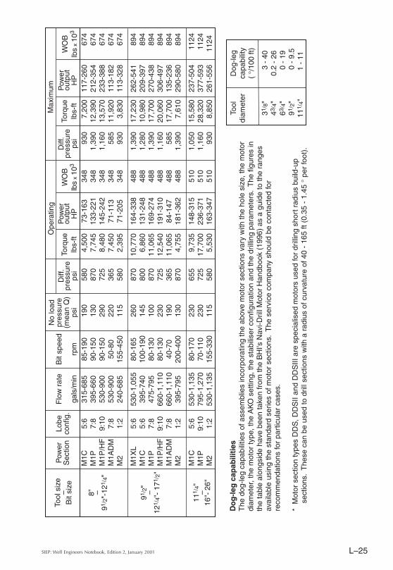
Do
g-l
eg c
apab
iliti
esT
he d
og-le
g ca
pabi
litie
s of
ass
embl
ies
inco
rpor
atin
g th
e ab
ove
mot
or s
ectio
ns v
ary
with
the
hole
siz
e, th
e m
otor
di
amet
er, t
he m
otor
type
, the
AK
O s
ettin
g, th
e st
abili
ser
conf
igur
atio
n an
d th
e dr
illin
g pa
ram
eter
s. T
he fi
gure
s in
th
e ta
ble
alon
gsid
e ha
ve b
een
take
n fr
om th
e B
HI's
Nav
i-Dril
l Mot
or H
andb
ook
(199
6) a
s a
guid
e to
the
rang
es
avai
labl
e us
ing
the
stan
dard
ser
ies
of m
otor
sec
tions
. T
he s
ervi
ce c
ompa
ny s
houl
d be
con
tact
ed fo
r re
com
men
datio
ns fo
r pa
rtic
ular
cas
es.
* M
otor
sec
tion
type
s D
DS
, DD
SII
and
DD
SIII
are
spe
cial
ised
mot
ors
used
for
drill
ing
shor
t rad
ius
build
-up
sect
ions
. T
hese
can
be
used
to d
rill s
ectio
ns w
ith a
rad
ius
of c
urva
ture
of 4
0 -
165
ft (0
.35
- 1.
45 °
per
foot
).
Tool
Dog
-leg
diam
eter
capa
bilit
y(
°/10
0 ft)
31/ 8
"
3 -
4043
/ 4"
0.2
- 26
63/ 4
"
0 -
1991
/ 2"
0
- 9
.511
1 /4"
1
- 11
SIEP: Well Engineers Notebook, Edition 2, January 2001L–26
Turb
odril
ls fo
r st
raig
ht h
oles
Turb
odril
ls fo
r de
viat
ed h
oles
Nom
inal
siz
e5"
71/ 4
"71
/ 4"
91/ 2
"91
/ 2"
33/ 8
"43
/ 4"
43/ 4
"65
/ 8"
91/ 2
"91
/ 2"
Type
T2
T2
T3
T2
T3
FB
SF
BS
MK
2F
BS
SB
SS
BS
Sta
ndar
dH
igh
flow
OD
5"73
/ 8"
73/ 8
"91
7 /32
"91
7 /32
"33
/ 8"
43/ 4
"43
/ 4"
65/ 8
"91
/ 2"
91/ 2
"B
it si
ze55
/ 8"-
63/ 4
"81
/ 2"-
95/ 8
"81
/ 2"-
95/ 8
"11
"-15
"11
"-15
"33
/ 4"-
53/ 8
"55
/ 8"-
63/ 4
"55
/ 8"-
63/ 4
"75
/ 8"-
97/ 8
"12
1 /4"
-171
/ 2"
121 /
4"-1
71/ 2
"S
peed
ran
ge (
rpm
)80
0-1,
800
700-
1,40
070
0-1,
400
400-
1000
300-
700
300-
700
Ben
t hou
sing
ang
le :
Sta
ndar
d1°
1°1°
1°3 /
4°3 /
4°A
vaila
ble
11/ 4
°, 1
1 /2°
3 /
4°,1
1 /4°
1 /2°
,1°
1 /2°
,1°
Dog
-leg
angl
e ca
pabi
lity
with
sta
ndar
d be
nt h
ousi
ng (
°/10
0ft -
°/3
0 m
)13
810
-12
6-8
44
Nom
inal
flow
rat
e(g
pm)
160
475
475
650
650
100
160
200
475
650
650
(l/se
c)10
3030
4141
6.3
1012
.630
4141
Pre
ssur
e dr
op(p
si)
1,43
51,
510
2,15
01,
525
2,21
01,
537
1,41
51,
598
1,87
5(k
Pa)
9,90
010
,400
14,8
0010
,500
15,2
0010
,600
9,80
011
,000
12,9
00P
ower
(HP
)78
243
365
379
568
5174
104
280
520
520
(kW
)58
181
272
283
424
3855
7820
938
838
8To
rque Max
imum
drlg
(lbs-
ft)
1,47
52,
460
5,00
05,
000
(N-m
)2,
000
3,35
06,
780
6,78
0 S
talli
ng(lb
s-ft)
32
586
0(N
-m)
440
1,16
0
NE
YR
FO
R T
UR
BIN
E D
ATA
Not
e :
The
pre
ssur
e dr
op, p
ower
and
torq
ue fi
gure
s gi
ven
abov
e ar
e va
lid fo
r th
e no
min
al fl
ow r
ate,
an
d fo
r a
drill
ing
fluid
den
sity
of 0
.52
psi/f
t or
11.7
5 kP
a/m
L–27SIEP: Well Engineers Notebook, Edition 2, January 2001
No
tes
on
tab
le*
Whi
chev
er is
app
licab
le**
If a
wire
line
surv
ey is
not
mad
e fr
om s
urfa
ce, i
t sho
uld
over
lap
at le
ast 1
000
ft (3
00 m
) of
the
prev
ious
su
rvey
. M
agne
tic s
urve
ys s
houl
d be
take
n in
to th
e la
st c
asin
g sh
oe.
1.IN
(F
IND
S o
r R
IGS
) to
rep
lace
GM
S if
ava
ilabl
e.2.
Whe
n co
nduc
tors
hav
e be
en b
atch
inst
alle
d, a
ll sh
ould
be
clea
ned
out a
nd s
urve
yed
prio
r to
dril
ling
the
first
wel
l.3.
Can
use
MW
D a
nd E
MS
whe
n th
ere
are
prob
lem
s of
get
ting
gyro
dow
n. R
un E
MS
prio
r to
run
ning
ca
sing
.4.
EM
S o
r D
ip M
eter
sur
vey
allo
wed
bel
ow th
e to
p of
the
low
est h
ydro
carb
on b
earin
g zo
ne (
in o
pen
hole
).5.
In h
ot w
ells
>12
0°C
(25
0°F
) th
ere
may
not
be
enou
gh r
oom
for
the
gyro
hea
t shi
eld.
Run
EM
S p
rior
to
runn
ing
casi
ng.
6.E
SS
is p
refe
rred
but
MS
S m
ay b
e us
ed.
7.G
MS
/EM
S m
ust b
e ta
ken
prio
r to
ent
erin
g an
y po
tent
ial z
one
that
cou
ld b
low
out
.8.
GM
S/E
MS
may
be
omitt
ed w
here
it is
pro
ven
that
the
wel
l will
not
pen
etra
te a
pot
entia
l blo
w o
ut z
one
in th
e ne
xt o
pen
hole
sec
tion
and
(1)
ther
e is
a G
MS
/EM
S in
th
e pr
evio
us s
ectio
n an
d (2
) th
e op
en h
ole
mag
netic
sur
vey
of th
at s
ectio
n is
goo
d.9.
GM
S s
urve
ys s
houl
d be
eve
ry 1
00 ft
(25
m),
but
this
sho
uld
be r
educ
ed to
eve
ry 5
0 ft
(15m
) th
roug
h se
ctio
ns w
ith d
ogle
gs o
ver
2.5°
/100
ft (
2.5°
/30m
).10
.Sur
vey
ever
y st
and
(90
ft) w
hen
usin
g M
WD
. Int
erva
l may
be
incr
ease
d to
300
ft (
100
m)
whe
n us
ing
an E
SS
.11
.IN
(R
IGS
) m
ay b
e co
nsid
ered
in s
peci
al c
ases
of h
igh
accu
racy
req
uire
men
ts.
12.E
MS
to b
e ta
ken
whe
n M
WD
/ST
/ES
S s
urve
ys h
ave
ques
tiona
ble
qual
ity.
13.W
here
crit
eria
for
relie
f wel
l dril
ling
have
bee
n re
laxe
d, in
clin
atio
n on
ly s
urve
ys m
ay b
e co
nsid
ered
.14
.Sur
vey
ever
y st
and
(90
ft) w
hen
usin
g E
MS
, but
this
sho
uld
be r
educ
ed to
eve
ry s
ingl
e (3
0 ft)
thro
ugh
sect
ions
with
dog
legs
ove
r 2.
5°/1
00 ft
(2.
5°/3
0 m
).
FR
EQ
UE
NC
Y A
ND
TY
PE
S O
F S
UR
VE
YS
TO
BE
TA
KE
N
GS
S=
Gyr
o S
ingl
e S
hot (
Sur
face
rea
d-ou
t pre
ferr
ed)
MW
D=
Mea
sure
men
t Whi
le D
rillin
gS
T=
Ste
erin
g To
olE
SS
=E
lect
roni
c M
agne
tic S
ingl
e S
hot
MS
S=
Mag
netic
Sin
gle
Sho
t (E
SS
pre
ferr
ed)
DIP
=D
ip M
eter
Log
(w
hich
giv
es g
ood
surv
ey r
esul
ts)
EM
S=
Ele
ctro
nic
Mag
netic
Mul
ti-S
hot
GM
S=
Gyr
o M
ulti-
Sho
t (N
orth
See
king
Gyr
o pr
efer
red)
IN=
Iner
tial N
avig
atio
nM
MS
=M
agne
tic M
ulti-
Sho
t (E
MS
pre
ferr
ed)
Pla
tform
/Clu
ster
/Tem
plat
e W
ells
and
Oth
er W
ells
Isol
ated
ver
tical
wel
lsD
urin
g D
rillin
gVer
ifica
tion
Sur
vey
Dur
ing
Dril
ling
Ver
ifica
tion
Sur
vey
Dur
ing
Dril
ling
Ver
ifica
tion
Sur
vey
Type
of
Sur
vey
Type
of
Sur
vey
Type
of
Sur
vey
Type
of
Sur
vey
Sur
vey
Sur
vey
Inte
rval
**S
urve
yIn
terv
al**
Sur
vey
Inte
rval
**S
urve
yIn
terv
al**
Sto
ve P
ipe/
Fou
ndat
ion
Pile
*N
one
Non
eN
one
Non
e
Mar
ine
Con
duct
or*
GS
S30
ft/
GM
S25
ftE
SS
at s
ectio
nG
MS
/EM
S50
ft10
m1,
28m
6,13
TD
1,7,
8,14
15 m
Con
duct
or S
trin
g (2
0/18
5 /8"
Cas
ing)
GS
S/M
WD
/ST
/ES
S30
-90
ftG
MS
100
ftM
WD
/ST
/ES
S30
0 ft
GM
S/E
MS
100
ft6,
10,1
210
-30
m1,
925
m6,
10,1
2,13
100
m1,
7,8,
9,14
25 m
Sur
face
Str
ing
(133
/ 8"
Cas
ing)
MW
D/S
T/E
SS
30-9
0 ft
GM
S10
0 ft
MW
D/S
T/E
SS
300
ftG
MS
/EM
S10
0 ft
6,10
,12
10-3
0 m
1,9
25 m
6,10
,12,
1310
0 m
1,7,
8,9,
1425
m
Inte
rmed
iate
Str
ing
(95 /
8" c
asin
g)M
WD
/ST
/ES
S30
-90
ftG
MS
100
ftM
WD
/ST
/ES
S30
0 ft
GM
S/E
MS
100
ft6,
10,1
210
-30
m1,
3,9
25 m
6,10
,12,
1310
0 m
1,7,
9,14
25 m
Pro
duct
ion
Str
ing
(7"
Cas
ing/
Line
r)M
WD
/ST
/ES
S30
-90
ftG
MS
100
ft M
WD
/ST
/ES
S30
0 ft
GM
S/E
MS
100
ft6,
10,1
210
-30
m4,
9,11
25 m
6,10
,12
100
m4,
9,14
25 m
Pro
duct
ion
Line
r (4
1 /2"
Lin
er)
ES
S/E
MS
as r
equi
red
GM
S/E
MS
100
ftE
SS
/EM
S/D
IP30
0 ft
EM
S/D
IP10
0 ft
4,6
4,5,
925
m4,
610
0 m
425
m
SIEP: Well Engineers Notebook, Edition 2, January 2001L–28
Totcos are normally run by the driller. The pre-survey checklist and running procedure are given below. (When using a magnetic single shot tool for inclination only surveys follow the running procedure for MSS.)1. Check that the instrument landing assembly will seat correctly in the landing ring
(Totco ring), and not jam or land eccentrically.2. Install the landing ring in the proper place when making up the BHA.3. Avoid landing the instrument directly on top of bit, mud motor or turbine. The
instrument could get stuck and furthermore make circulation impossible.4. Check that the fishing tool will fit over the fishing neck.5. Check that the instrument will pass the BHA above the landing ring and not hang up
(e.g. in the jar).6. Check that the instrument kit box is complete and that the angle units have been
checked in the workshop before delivery to the well site. Check that no angle unit has been used more than 25 times after calibration.
7. Use sinker bars if the drilling fluid has a high density and/or is viscous.8. Before surveying circulate sufficiently to avoid a back flow of cuttings into the BHA.9. Estimate the time lapse. This should be equal to the sum of the times required to:
- mount the instrument in the barrel- run the instrument through the drill string- provide a safety margin of a few minutes (3-5 minutes) in case of any delays.
PRE-SURVEY CHECKLISTS
Totcos
Magnetic Single Shots
An OU representative should ensure that the following is carried out :1.Check that the required length of NMDC is available.2.Check that the instrument landing assembly will seat correctly in the landing ring
(TOTCO ring), and will not jam or land eccentrically.3.Check whether the instrument is to be top or bottom landed or used with a mule shoe.4. Install the landing ring in the proper place when making up the BHA. Avoid landing the
instrument directly on top of bit, mud motor or turbine. The instrument could get stuck and furthermore make it impossible to circulate.
5.Check that the instrument will pass the rest of the BHA above the landing ring and not hang up (e.g. in the jar).
6.Check that the instrument kit box is complete and that the angle units have been checked in the workshop before delivery to the well site. Check that no angle unit has been used more than 25 times after calibration.Specifically check that the kit box includes:• two angle units of each range, which should be used alternately• batteries specified for the instrument• film discs• developing chemicalsand ensure that the film is kept dry before the survey is run.
7.Check the angle unit in the field test stand. Ensure that the angle unit inclination readings agree with the field test stand inclinations.
L–29SIEP: Well Engineers Notebook, Edition 2, January 2001
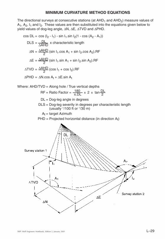
The directional surveys at consecutive stations (at AHD1 and AHD2) measure values of A1, A2, I1 and I2. These values are then substituted into the equations given below to yield values of dog-leg angle, ∆N, ∆E, ∆TVD and ∆PHD.
cos DL = cos (I2 - I1) - sin I1.sin I2(1 - cos (A2 - A1))
DLS = DL x characteristic length∆AHD
∆N = ∆AHD (sin I1.cos A1 + sin I2.cos A2).RF2
∆E = ∆AHD (sin I1.sin A1 + sin I2.sin A2).RF2
∆TVD = ∆AHD (cos I1 + cos I2).RF2
∆PHD = ∆N.cos At + ∆E.sin At
Where: AHD/TVD = Along hole / True vertical depths
RF = Ratio Factor = 180 x 2 x tan DL π.DL 2DL = Dog-leg angle in degrees
DLS = Dog-leg severity in degrees per characteristic length (usually °/100 ft or °/30 m)
At = target AzimuthPHD = Projected horizontal distance (in direction At)
MINIMUM CURVATURE METHOD EQUATIONS
SIEP: Well Engineers Notebook, Edition 2, January 2001L–30
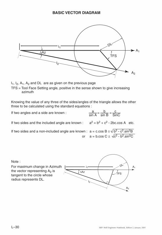
BASIC VECTOR DIAGRAM
I1, I2, A1, A2 and DL are as given on the previous pageTFS = Tool Face Setting angle, positive in the sense shown to give increasing
azimuth
Knowing the value of any three of the sides/angles of the triangle allows the other three to be calculated using the standard equations :
If two angles and a side are known : a = b = csin A sin B SinC
If two sides and the included angle are known : a2 = b2 + c2 - 2bc.cos A etc.
If two sides and a non-included angle are known : a = c.cos B ± b2 - c2.sin2B or a = b.cos C ± c2 - b2.sin2C
Note : For maximum change in Azimuth the vector representing A2 is tangent to the circle whose radius represents DL.