61
WELLSITE DESIGN SPACING R ECOMMENDATIONS INDUSTRY R ECOMMENDED PRACTICE (IRP) VOLUME 20 - 2008 SANCTIONED FEBRUARY 2008
| Date post: | 07-Aug-2018 |
| Category: |
Documents |
| Upload: | wil-vasquez-c |
| View: | 239 times |
| Download: | 1 times |
8/20/2019 Wellsite Design Spacing Recommendations
http://slidepdf.com/reader/full/wellsite-design-spacing-recommendations 1/61
WELLSITE DESIGN SPACING
R ECOMMENDATIONS
INDUSTRY R ECOMMENDED
PRACTICE (IRP)
VOLUME 20 - 2008
SANCTIONED FEBRUARY 2008

8/20/2019 Wellsite Design Spacing Recommendations
http://slidepdf.com/reader/full/wellsite-design-spacing-recommendations 2/61
Copyright/Right to Reproduce
Copyright for this document is held by Enform, 2006. All rights reserved. No part of this
document may be reproduced, republished, redistributed, stored in a retrieval system, or
transmitted unless the user references the copyright ownership of Enform.
Disclaimer
This IRP is a set of best practices and guidelines compiled by knowledgeable and
experienced industry and government personnel. It is intended to provide the owner,operator, and contractors with advice regarding the specific topic. It was developed under
the auspices of the Drilling and Completions Committee (DACC).
The recommendations set out in this IRP are meant to allow flexibility and must be used in
conjunction with competent technical judgment. It remains the responsibility of the user ofthe IRP to judge its suitability for a particular application.
If there is any inconsistency or conflict between any of the recommended practicescontained in the IRP and the applicable legislative requirement, the legislative requirement
shall prevail.
Every effort has been made to ensure the accuracy and reliability of the data andrecommendations contained in the IRP. However, DACC, its subcommittees, and individual
contributors make no representation, warranty, or guarantee in connection with the
publication of the contents of any IRP recommendation, and hereby disclaim liability orresponsibility for loss or damage resulting from the use of this IRP, or for any violation of
any legislative requirements.
Availability
This document, as well as future editions, is available from
Enform
1538 – 25th Avenue NECalgary, AB T2E 8Y3
Phone: (403) 250-9606Fax: (403) 291-9408
Website: www.enform.ca
8/20/2019 Wellsite Design Spacing Recommendations
http://slidepdf.com/reader/full/wellsite-design-spacing-recommendations 3/61
Wellsite Design Spacing Recommendations
February 2008 i
TABLE OF CONTENTS
List of Figures .................................................................................................... ii
List of Photos .................................................................................................... iii
Preface ...................................................................................................... iv
Purpose ........................................................................................................ iv
Audience ...................................................................................................... iv
Scope and Limitations .................................................................................. iv
Method of Development ................................................................................ v
Further Developments ................................................................................... v
Revision History ................................................................................... vi
Sanction ....................................................................................................... vi
Acknowledgements ...................................................................................... vi
IRP 20 Development Committee ............................................................. vi
Wellsite Spacing Committee .................................................................. vii
20.1 Well Spacing Templates ........................................................................... 1
20.2 Flare Pits and Stacks ................................................................................ 2
20.2.1 Alberta ................................................................................................ 2
20.2.2 ASRD ................................................................................................... 2
20.2.3
ERCB ................................................................................................... 2
20.2.4 British Columbia .................................................................................. 2
20.2.5 OGC ..................................................................................................... 2
20.3 Interprovincial Spacing Requirements ..................................................... 3
20.4 Lease Construction Spacing Checklist ...................................................... 4
20.5 Critical Concerns ...................................................................................... 5
20.5.1 Positioning of Flare Stacks and Pits .................................................... 5
20.5.2 Turning Radius on Access Roads ......................................................... 5
20.5.3 Sewage (Tanks/Trenches/Pits) .......................................................... 5
20.5.4
Wellsite Lighting ................................................................................. 5
20.5.5 Escape Lines........................................................................................ 5
20.6 Templates and Photographs ..................................................................... 6
Figure 12: Interprovincial Spacing Requirements ............................................ 35
Figure 12.1: Weblink locations ......................................................................... 43
Appendix A: Lease Construction Spacing Information Checklist ....................... 45
8/20/2019 Wellsite Design Spacing Recommendations
http://slidepdf.com/reader/full/wellsite-design-spacing-recommendations 4/61
Wellsite Design Spacing Recommendations
ii February 2008
LIST OF FIGURES
Figure 1A: Deep Oil Vertical Profile: Typical Vertical Profile............................................. 7
Figure 1B: Deep Oil Rig Layout Working Area: Typical Rig Layout.................................... 7
Figure 1C: Deep Oil Completion Operation: Typical Service Well ..................................... 8
Figure 1D: Deep Oil Production Facility: Typical Production Facility .................................. 8
Figure 2A: Deep Gas Vertical Profile: Typical Vertical Profile ......................................... 10
Figure 2B: Deep Gas Rig Layout Working Area: Typical Rig Layout ................................ 10
Figure 2C: Deep Gas Completion Operation: Typical Service Well .................................. 11
Figure 2D: Deep Gas Production Facility: Typical Production Facility .............................. 11
Figure 3A: Shallow Gas Vertical Profile: Typical Vertical Profile ..................................... 13
Figure 3B: Shallow Gas Rig Layout Working Area: Typical Rig Layout ............................ 13
Figure 3C: Shallow Gas Completion Operation: Typical Service Well .............................. 14
Figure 3D: Shallow Gas Production Facility: Typical Production Facility ........................... 14
Figure 4A: Prairie Shallow Gas Low Impact Vertical Profile: Typical Vertical Profile ........... 16
Figure 4B: Prairie Shallow Gas Low Impact Rig Layout Working Area: Typical Rig Layout .. 16
Figure 4C: Prairie Shallow Gas Low Impact Completion Operation: Typical Service Well.... 17
Figure 4D: Prairie Shallow Gas Low Impact Production Facility: Typical Production Facility 17
Figure 5A: Forested Area Shallow Gas Low Impact Vertical Profile: Typical Vertical Profile 19
Figure 5B: Forested Area Shallow Gas Low Impact Rig Layout Working Area: Typical Rig
Layout .................................................................................................................. 19
Figure 5C: Forested Area Shallow Gas Low Impact Completion Operation: Typical Service
Well ..................................................................................................................... 20
Figure 5D: Forested Area Shallow Gas Low Impact Production Facility: Typical Production
Facility ................................................................................................................. 20
Figure 6A: Shallow Gas Coil Tubing Vertical Profile: Typical Vertical Profile ..................... 21
Figure 6B: Shallow Gas Coil Tubing Rig Layout Working Area: Typical Rig Layout ............ 21
Figure 6C: Shallow Gas Coil Tubing Completion Operation: Typical Service Well .............. 22
Figure 6D: Shallow Gas Coil Tubing Production Facility: Typical Production Facility .......... 22
Figure 7A: Underbalanced Vertical Profile: Typical Vertical Profile .................................. 26
Figure 7B: Underbalanced Rig Layout Working Area: Typical Rig Layout ......................... 26 Figure 7C: Underbalanced Completion Operations: Typical Service Well ......................... 27
Figure 7D: Underbalanced Production Facility: Typical Production Facility ....................... 27
Figure 8A: Shallow Oil Vertical Profile: Typical Vertical Profile ....................................... 29
Figure 8B: Shallow Oil Rig Layout Working Area: Typical Rig Layout .............................. 29
Figure 8C: Shallow Oil Completion Operation: Typical Service Well ................................ 30
Figure 8D: Shallow Oil Production Facility: Typical Production Facility ............................ 30
Figure 9A: Blank Template ...................................................................................... 31
Figure 9B: Blank Template ...................................................................................... 31
Figure 10: Sketch Plan: Typical Alberta Flare Pit ......................................................... 33
Figure 11: Sketch Plan: Typical British Columbia Flare Pit ............................................ 34
8/20/2019 Wellsite Design Spacing Recommendations
http://slidepdf.com/reader/full/wellsite-design-spacing-recommendations 5/61
Wellsite Design Spacing Recommendations
February 2008 iii
LIST OF PHOTOS
Photo 1: Deep Oil Drilling Operation ........................................................................... 9
Photo 2: Deep Oil Completion Operation ...................................................................... 9
Photo 3: Deep Gas Drilling Operation ........................................................................ 12
Photo 4: Deep Gas Completion Operation .................................................................. 12
Photo 5: Shallow Gas Drilling Operation .................................................................... 15
Photo 6: Shallow Gas Completion Operation .............................................................. 15
Photo 7: Prairie Shallow Gas Low Impact Drilling Operation .......................................... 18
Photo 8: Shallow Gas Coil Tubing Drilling Operation .................................................... 23
Photo 9: Deep Gas Coil Tubing Completion Operation .................................................. 23
Photo 10: Deep Gas Coil Tubing Completion Operations ............................................... 24
Photo 11: Shallow Gas Coil Tubing Completion Operation ............................................ 24
Photo 12: Shallow Gas Coil Tubing Completion Operation ............................................ 25
Photo 13: Underbalanced Completion ........................................................................ 28 Photo 14: Corehole Mining Rig ................................................................................. 32
Photo 15: Corehole Single Drilling Rig ....................................................................... 32
Photo 16: Adding Wells to Existing Pads .................................................................... 33
Photo 17: Many Wells on a Pad Requiring Downhole Avoidance ..................................... 33
Photo 18: Screwjacks Instead of Pumpjacks .............................................................. 34
Photo 19: Vertical Oil Well with Slant Water Wells with Production Facilities .................... 34
Photo 20: Vertical Oil Well with Slant Oil and Water Wells ............................................ 35
Photo 21: Underground Facilities May Impact Well Positioning ...................................... 35
Photo 22: Stockpiling to Drill Through the Summer at a Remote Site ............................. 36
Photo 23: Sag D .................................................................................................... 36
Photo 24: Rig Moves .............................................................................................. 37
Photo 25: Rig Moves .............................................................................................. 37
Photo 26: Rig Moves .............................................................................................. 38
8/20/2019 Wellsite Design Spacing Recommendations
http://slidepdf.com/reader/full/wellsite-design-spacing-recommendations 6/61
Wellsite Design Spacing Recommendations
iv February 2008
PREFACE
PURPOSE
The purpose of Industry Recommended Practice (IRP 20) Welsite Design Spacing
Recommendations is to provide guidelines on wellsite size and spacing. Specifically,
this IRP aims to provide a set of best practices that will ensure consistent and legal
lease size information for typical Drilling, Completions, and Production Facilities in
Alberta, British Columbia, Saskatchewan, Manitoba, the North West Territories, and
Nunavut. Another objective of the IRP is to ensure that consistent provincial spacing
requirements are followed when a lease is being designed.
AUDIENCE
The intended audience of this document includes
oil and gas company companies,
construction, geology, geophysics, drilling, completions, and production
facilities personnel,
industry training personnel,
survey companies, and
regulatory bodies.
SCOPE AND LIMITATIONS This document contains the following information about wellsite size and spacing:
Well spacing templates or overlays
Flare pits and flare stacks
Interprovincial spacing requirements
Lease construction spacing requirements
The WellSite Spacing Committee tried to ensure consistency between provinces with
regard to wellsite size, while still maintaining the legal spacing required by the
governing regulatory bodies. However, there are still discrepancies betweenprovinces in some areas. Therefore, it is necessary to verify spacing requirements.
8/20/2019 Wellsite Design Spacing Recommendations
http://slidepdf.com/reader/full/wellsite-design-spacing-recommendations 7/61
Wellsite Design Spacing Recommendations
February 2008 v
METHOD OF DEVELOPMENT
Industry Recommended Practices are developed with the involvement of both the
upstream petroleum industry and relevant regulators. Enform serves as the
custodian of all IRPs. IRPs provide a unique resource outside of direct regulatory
intervention.
This is the first edition of IRP 20. The content was developed by the Wellsite Spacing
Committee, a subcommittee of the Drilling and Completions Committee (DACC). The
committee consisted of representatives from industry and various government
agencies. In March 2003, the committee released the draft “Wellsite Spacing
Recommendations” to industry and government for feedback. At that point, the IRP
20 Development Committee began the process of developing the recommendations
into an Industry Recommended Practice.
FURTHER DEVELOPMENTS Since the release of the “Wellsite Spacing Recommendations” in March 2003, Alberta
Sustainable Resource Development (ASRD) has incorporated the Lease Spacing
Information Checklist and the Spacing Overlays within the newly structured
Environmental Field Reports (EFR). The Oil and Gas Commission (OGC) - British
Columbia will be including the information for new well applications in their Well
Authority (WA) forms in British Columbia by the summer of 2005.
In addition, Enform has updated changes to its Lease Development and Reclamation
course to incorporate the “Wellsite Spacing Recommendations” into the course.
Enform also added an Environmental Field Report (EFR) Workshop in Spring 2005,
which addresses Wellsite Spacing Recommendations.As of winter 2005, there are no changes to the wording in the regulations regarding
flare pits and stacks. However, ASRD is in the process of drafting a discussion paper
on proposed changes for legislative planning purposes. The Act and regulations are
due for a major overhaul. ASRD will be submitting issues such as those provided by
the Wellsite Spacing Committee to the legislative planning personnel to prepare a
discussion paper. This paper will be circulated to all internal (government) and
external (industry) stakeholders for input within the next year or two. The Wellsite
Spacing Committee identified a need for more consistent wording regarding Flare Pit
and Flare Stack regulations between ASRD and the ERCB regulations.
8/20/2019 Wellsite Design Spacing Recommendations
http://slidepdf.com/reader/full/wellsite-design-spacing-recommendations 8/61
Wellsite Design Spacing Recommendations
vi February 2008
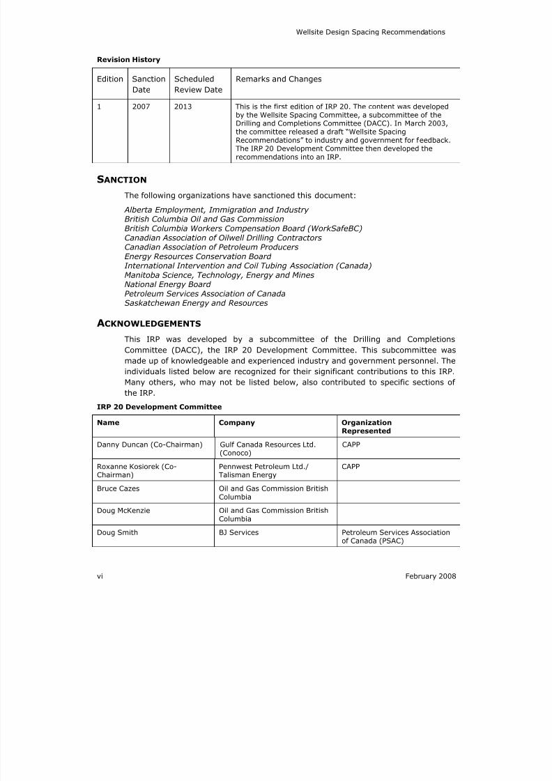
Revision History
Edition Sanction
Date
Scheduled
Review Date
Remarks and Changes
1 2007 2013 This is the first edition of IRP 20. The content was developed
by the Wellsite Spacing Committee, a subcommittee of theDrilling and Completions Committee (DACC). In March 2003,the committee released a draft “Wellsite SpacingRecommendations” to industry and government for feedback.The IRP 20 Development Committee then developed therecommendations into an IRP.
SANCTION
The following organizations have sanctioned this document:
Alberta Employment, Immigration and IndustryBritish Columbia Oil and Gas Commission
British Columbia Workers Compensation Board (WorkSafeBC)
Canadian Association of Oilwell Drilling ContractorsCanadian Association of Petroleum Producers
Energy Resources Conservation BoardInternational Intervention and Coil Tubing Association (Canada)
Manitoba Science, Technology, Energy and MinesNational Energy Board
Petroleum Services Association of CanadaSaskatchewan Energy and Resources
ACKNOWLEDGEMENTS
This IRP was developed by a subcommittee of the Drilling and Completions
Committee (DACC), the IRP 20 Development Committee. This subcommittee wasmade up of knowledgeable and experienced industry and government personnel. The
individuals listed below are recognized for their significant contributions to this IRP.
Many others, who may not be listed below, also contributed to specific sections of
the IRP.
IRP 20 Development Committee
Name Company OrganizationRepresented
Danny Duncan (Co-Chairman) Gulf Canada Resources Ltd.(Conoco)
CAPP
Roxanne Kosiorek (Co-Chairman) Pennwest Petroleum Ltd./Talisman Energy CAPP
Bruce Cazes Oil and Gas Commission BritishColumbia
Doug McKenzie Oil and Gas Commission BritishColumbia
Doug Smith BJ Services Petroleum Services Associationof Canada (PSAC)
8/20/2019 Wellsite Design Spacing Recommendations
http://slidepdf.com/reader/full/wellsite-design-spacing-recommendations 9/61
Wellsite Design Spacing Recommendations
February 2008 vii
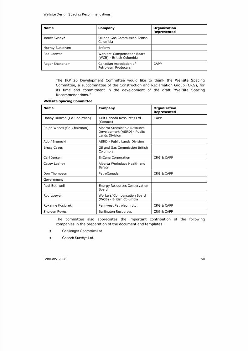
Name Company OrganizationRepresented
James Gladyz Oil and Gas Commission BritishColumbia
Murray Sunstrum Enform
Rod Loewen Workers’ Compensation Board(WCB) - British Columbia
Roger Shanenam Canadian Association ofPetroleum Producers
CAPP
The IRP 20 Development Committee would like to thank the Wellsite Spacing
Committee, a subcommittee of the Construction and Reclamation Group (CRG), for
its time and commitment in the development of the draft “Wellsite Spacing
Recommendations.”
Wellsite Spacing Committee
Name Company OrganizationRepresented
Danny Duncan (Co-Chairman) Gulf Canada Resources Ltd.(Conoco)
CAPP
Ralph Woods (Co-Chairman) Alberta Sustainable ResourceDevelopment (ASRD) - PublicLands Division
Adolf Bruneski ASRD - Public Lands Division
Bruce Cazes Oil and Gas Commission BritishColumbia
Carl Jensen EnCana Corporation CRG & CAPP
Casey Leahey Alberta Workplace Health andSafety
Don Thompson PetroCanada CRG & CAPP
Government
Paul Bothwell Energy Resources ConservationBoard
Rod Loewen Workers’ Compensation Board(WCB) - British Columbia
Roxanne Kosiorek Pennwest Petroleum Ltd. CRG & CAPP
Sheldon Reves Burlington Resources CRG & CAPP
The committee also appreciates the important contribution of the following
companies in the preparation of the document and templates:
Challenger Geomatics Ltd.
Caltech Surveys Ltd.

8/20/2019 Wellsite Design Spacing Recommendations
http://slidepdf.com/reader/full/wellsite-design-spacing-recommendations 10/61
8/20/2019 Wellsite Design Spacing Recommendations
http://slidepdf.com/reader/full/wellsite-design-spacing-recommendations 11/61
February 2008 1
20.1 WELL SPACING TEMPLATES
The size of the working area of a wellsite is most often determined by the size of the
drilling rig intended to drill the well. However, other factors that will have an
influence include the accessories needed for the drilling rig such as trailers forvarious critical crews, specialty equipment, type of drill sump, and often, the size of
the service rig and its associated equipment. The associated service rig equipment
often includes multiple trucks for fracturing operations, nitrogen trucks, and other
equipment.
This IRP stresses the importance of constructing a suitable-sized lease for the
equipment required to drill, complete, work over, and produce the well. There is also
a need to ensure proper access to mobilize the equipment. For example, the proper
vehicle turning radius must be determined prior to the movement of equipment on
the lease and on the access routes to the lease.
In addition to the working area, in many cases, additional space is required to meetthe cut/fill requirements, and to maintain a slope that is suitable and stable for the
type of soil used for the construction of the lease. For example, sandy soils will
require a wider area for slope than soils with high clay content. Additional area may
also be required for salvaged soil storage, snow storage, drainage ditches, storage
for bush piles during high fire season, berms, and other considerations.
This IRP provides templates that reflect the appropriate working area size,
considering such variations as rig sizes, service rigs, soils and terrain, and timing
(e.g., snow cover). Because of the variance in drill rig and service rig set-ups, there
may be many more variations that can be used. However, the IRP templates capture
the majority of operations. See 20.6 Templates and Photographs on page 6.
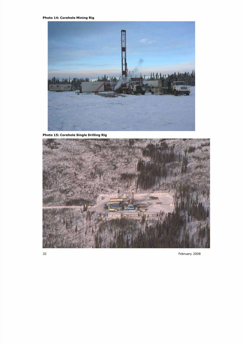
In addition, the IRP committee considered multiple well pads, which are often
constructed for shallow or heavy oil operations. The lease requirements for corehole
drilling usually associated with heavy oil programs were also considered. However,
we concluded that these situations vary a great deal depending on the operator and
the well layout conditions. As a result, they are not included in the IRP 20 templates.
However, the same logic used in the development of this IRP can be applied to other,
and all unique, lease configurations.
8/20/2019 Wellsite Design Spacing Recommendations
http://slidepdf.com/reader/full/wellsite-design-spacing-recommendations 12/61
2 February 2008
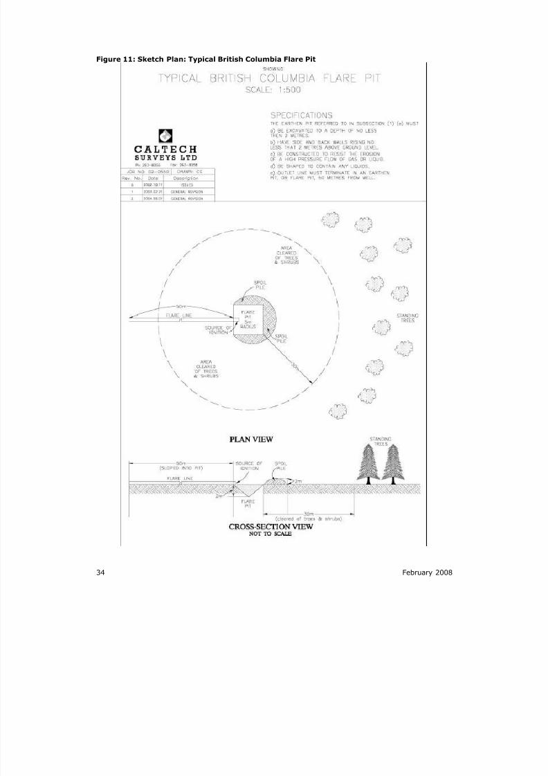
20.2 FLARE PITS AND STACKS
20.2.1 ALBERTA
In Alberta, the specifications required for a flare pit are as follows:
20.2.2 ASRD
The perimeter area around the flare pit has been cleared of all combustible debris
within 30 metres (100 ft.). A clear bare mineral soil surface extending at least 8
metres (26 ft.) around the flare pit perimeter must be maintained. The flare pit is so
constructed that burning debris cannot escape from the flare pit at any time.
(Alberta Forest and Prairie Protection Act, Part II)
20.2.3 ERCB
The flare pit must be constructed to contain a minimum of 8 cubic metres (283cu.ft.)of fluid. It must have side and back walls rising not less than 2 metres (7 ft.) above
ground level. It must be constructed to resist the erosion of a high-pressure flow of
gas or liquid. The flare pit must be located a minimum distance of 50 metres (164
ft.) from the well. (ERCB Oil and Gas Conservation Regulation 8.135(9))
20.2.4 BRITISH COLUMBIA
In British Columbia, the specifications required for flare pits and stacks are as
follows:
20.2.5 OGC
The minimum recommended blackened area of 30 metres (100 ft.) in forested areas
and 10 metres (33 ft.) in cultivated areas. A blackened area, free of vegetation and
with a radius of at least 1.5 times the stack height, be maintained around the base of
the flare stack or the end of a flare line to the following minimum distances: (i) 10
metres (33 ft.) in cultivated areas and (ii) 30 metres (100 ft.) in forested areas. (BC
Oil and Gas Commission Regulation 62(n)
The complete Spacing Requirements for the Flare Pit or Stack are listed in Figure 10
and Figure 11 of this IRP.
8/20/2019 Wellsite Design Spacing Recommendations
http://slidepdf.com/reader/full/wellsite-design-spacing-recommendations 13/61
February 2008 3
20.3 INTERPROVINCIAL SPACING
R EQUIREMENTS
The size of a wellsite is heavily influenced by the various regulations that apply to
the Oil and Gas Industry. To demonstrate the requirements of the various
government agencies, a table was generated indicating the minimum spacing
requirements as well as the associated regulation code that reflects the specific
standard for each province (see Figure 12 on page 42). This table was revised in
January 2005.
There is a discrepancy between government agencies in different provinces regarding
the minimum spacing requirements for the same type of operation. The committee
assumed that this discrepancy could be largely attributed to the conversion from
imperial units to metric units: some provinces rounded up, while others rounded
down. However, we were unable to standardize the distance or to resolve this issue.Therefore, this issue remains outstanding and should be reviewed and potentially
resolved by CAPP.
The committee was also concerned about when, why, and how some of the specific
rules were determined. After much discussion and limited success in discovering the
history, we concluded that there must have been some support for the set distances.
As a result, we did not change them. For example, there is a 25-metre (82-ft.) no-
smoking rule as opposed to a 50-metre (164-ft.) flare rule. Discussions suggested
that the flare has great potential for out-of-control burn and for radiant heat.
For further information, readers can refer to the ASRD ID 2002-01 Slope and Break
Setback Guidelines.
8/20/2019 Wellsite Design Spacing Recommendations
http://slidepdf.com/reader/full/wellsite-design-spacing-recommendations 14/61
4 February 2008
20.4 LEASE CONSTRUCTION SPACING
CHECKLIST
When wellsites are being built, another concern is that the constructed wellsite may
be too large or too small for the intended operations. An oversized lease obviously
does not have a substantial impact on the subsequent operations. However, it does
mean additional and unnecessary construction expense, as well as the unnecessary
disturbance of adjacent land. On the other hand, an undersized lease often results in
illegal operations, which could lead to the entire operation being shut down by a
Regulatory Agency. This situation also poses a potential safety issue for onsite
personnel and a potential for equipment damage.
The Lease Construction Spacing Information Checklist (see Appendix A) is intended
to provide the best possible wellsite construction specifications from a scout or
survey stage. For optimal wellsite sizing and spacing, the following elements shouldbe considered:
LSD (Legal Subdivision) location
Well type
Well depth
Future plans/Completions/Production
Rig type
Mud system
Drilling waste disposal
Flare requirements for drilling and production
Tank spacing requirements
Winter or summer drill
Berm requirements
Drainage ditches
Brush storage
Soil storage
Construction method
Wellsite working area and total area size
In addition, the templates provided in this document depict typical drilling or service
rig and associated equipment footprint requirements for drilling and completions
operations (see 20.6 Templates and Photographs on page 6).
8/20/2019 Wellsite Design Spacing Recommendations
http://slidepdf.com/reader/full/wellsite-design-spacing-recommendations 15/61
February 2008 5
20.5 CRITICAL CONCERNS
Various groups felt the following critical concerns should be included in IRP 20.
20.5.1 POSITIONING OF FLARE STACKS AND PITS
The position of the Flare Stacks and Pits is largely determined by the drilling rig,
service rig, and production facility. This positioning is not addressed in this IRP.
20.5.2 TURNING R ADIUS ON ACCESS R OADS
The design of a road (including the turning radius of corners and access onto the
lease) should be considered in the overall design of the access to a lease during the
scout or survey phase. The committee concluded that spacing issues beyond the
lease area do not apply to this IRP.
20.5.3 SEWAGE (TANKS/TRENCHES/PITS)
Spacing requirements for sewage lagoons and pits are addressed under section 65 of
Figure 12: Interprovincial Spacing Requirements on page 35 of this IRP.
In Alberta, sewage treatment and other issues are being addressed by the Private
Sewage Disposal Systems Temporary Work Camp Sewage Treatment Standards Sub-
Committee. The mandate of the subcommittee is to advise the Safety Codes Council,
and Plumbing Technical Council on the development of guidelines for sewage
treatment at relocatable industrial accommodations (work camps) that are
considered temporary in nature. Further discussion of spacing should be addressed
within this subcommittee.
In British Columbia, the WCB, OGC, and Regional Health Board refer to the BC Reg.
427/83 Industrial Camps Health Regulations and BC Reg. 411/85 Sewage Disposal
Regulation.
20.5.4 WELLSITE LIGHTING
Adequate lighting should be considered when designing a lease; however, it is not
within the mandate of the IRP 20 committee to address this concern.
20.5.5 ESCAPE LINES
Escape lines for drilling should be considered in the design of a lease. The well
spacing templates allow room to ensure adequate lease area for the inclusion of the
lines, and safe access around the lines. The guy lines should be adequately marked
for visibility and safety.
The following guidelines for determining the required distance as it relates to the
height (depending upon the rig’s size) can be used: single – 30 feet (9 m), double –
62 feet (19m), small triple - 100 feet (31 m), and large triple – 120 feet (37 m).
8/20/2019 Wellsite Design Spacing Recommendations
http://slidepdf.com/reader/full/wellsite-design-spacing-recommendations 16/61
6 February 2008
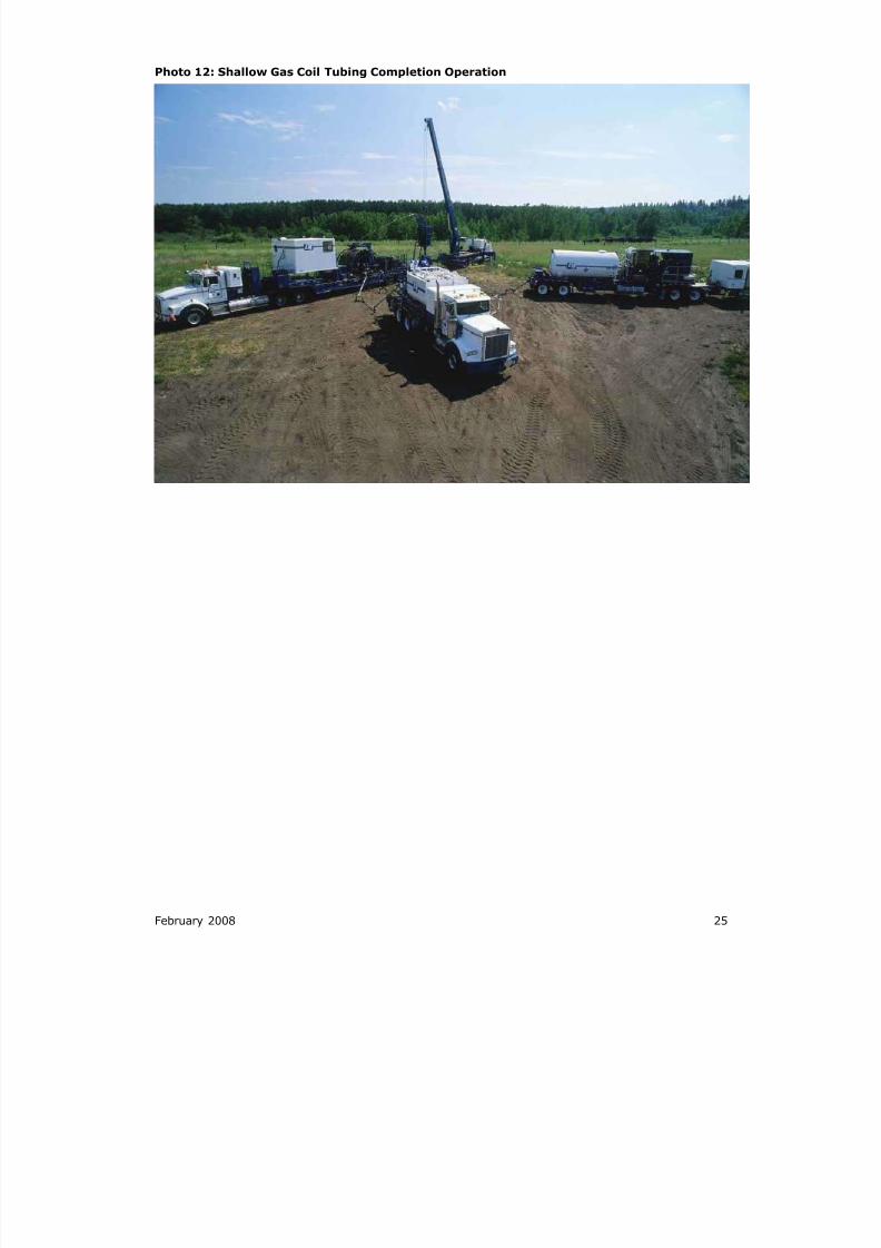
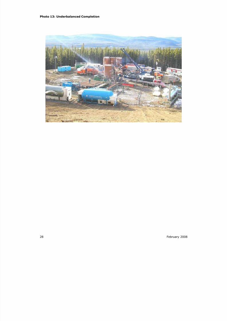
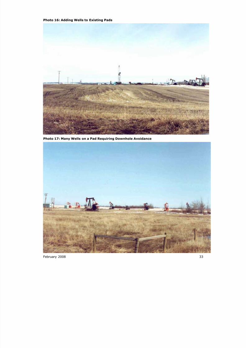
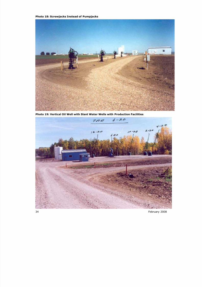
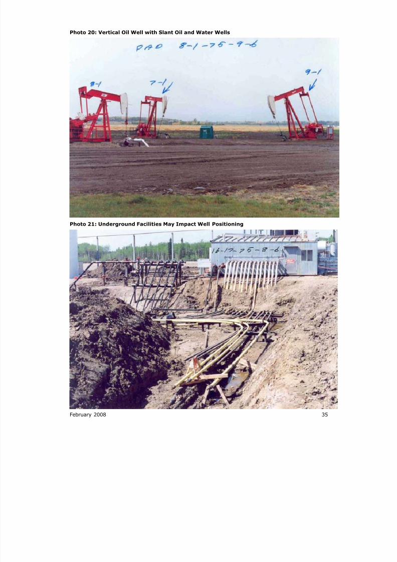
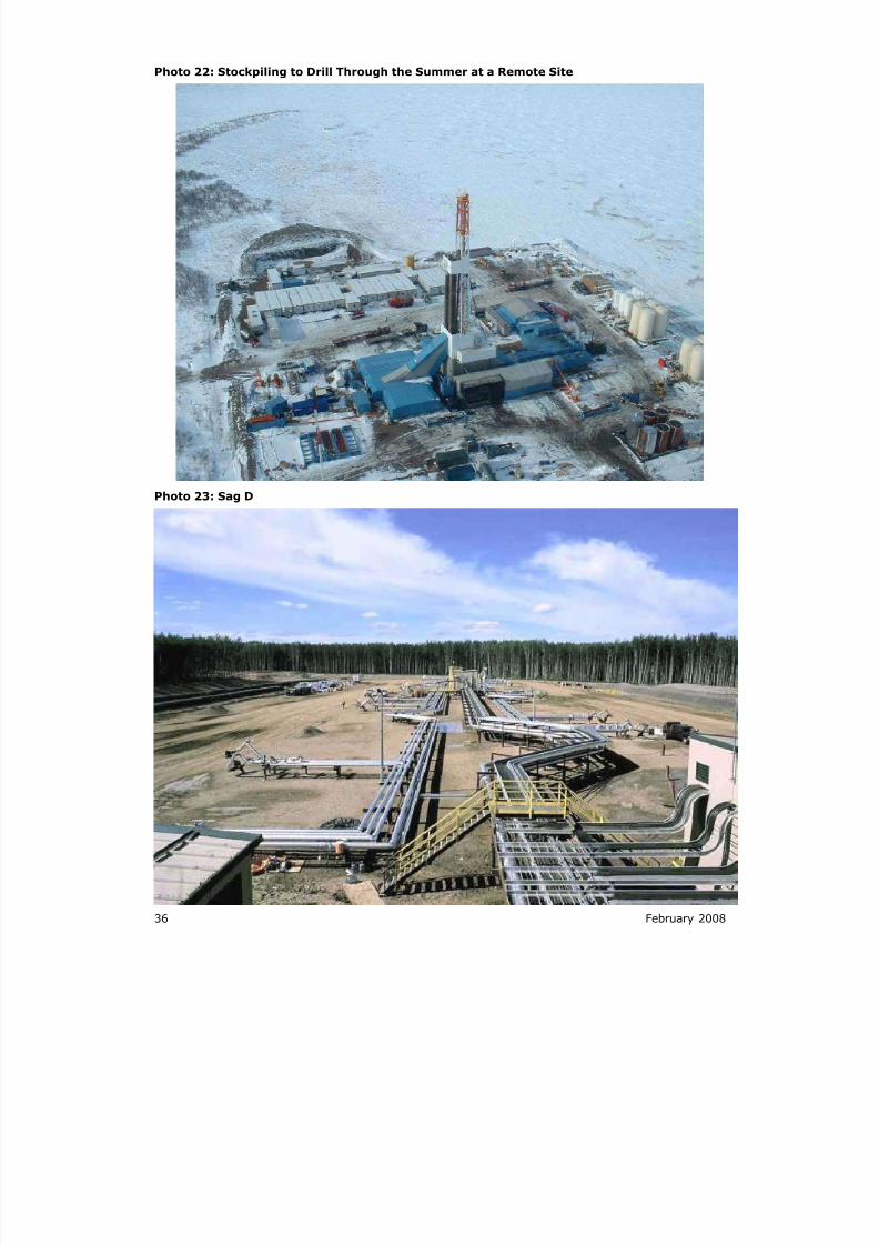
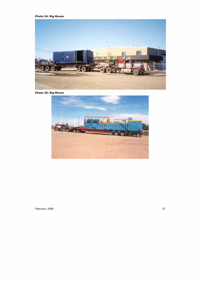
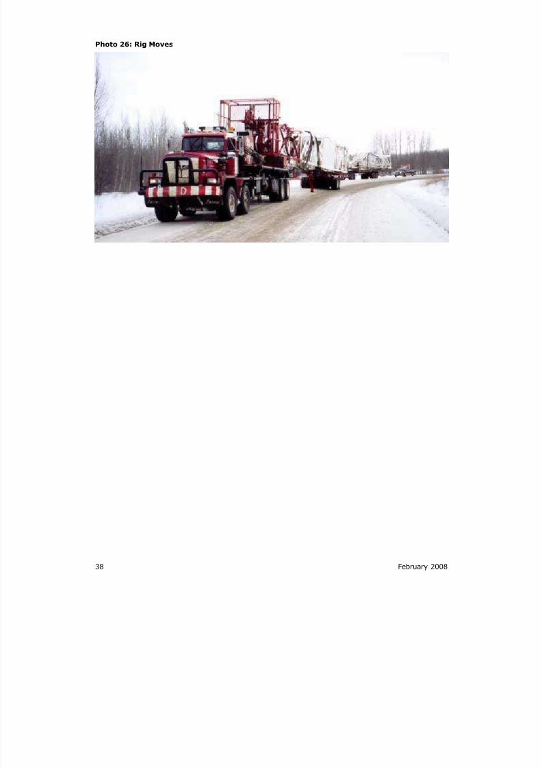
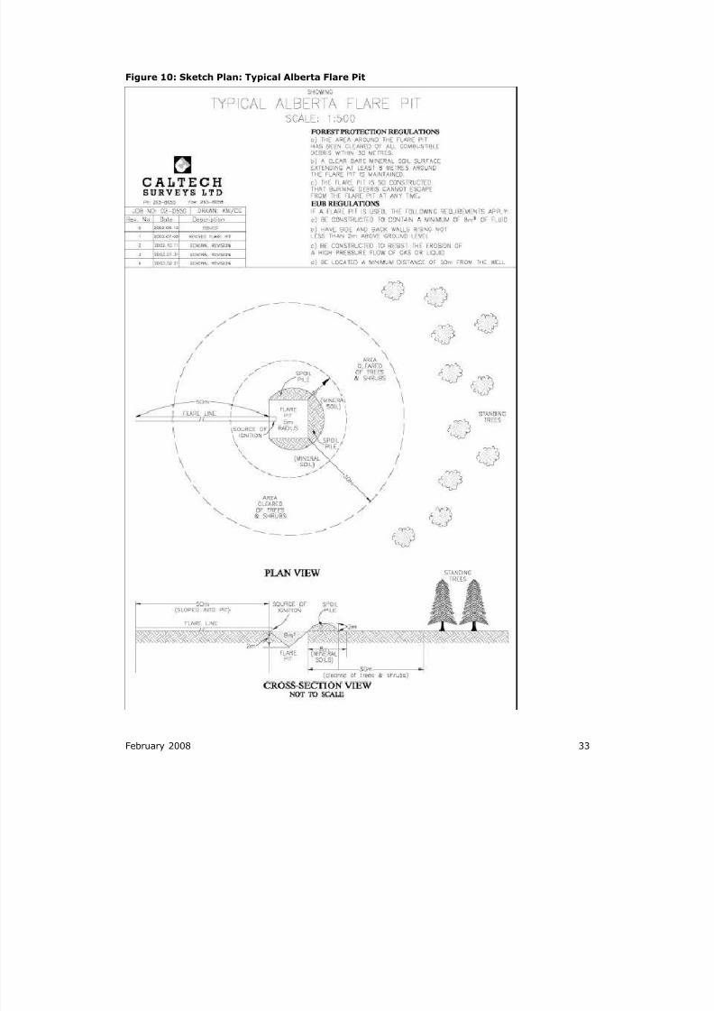
20.6 TEMPLATES AND PHOTOGRAPHS
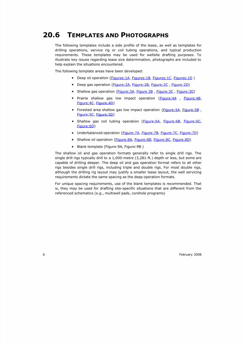
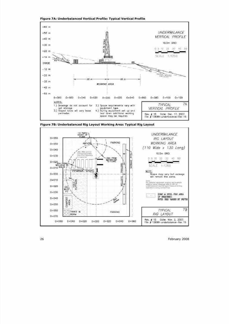
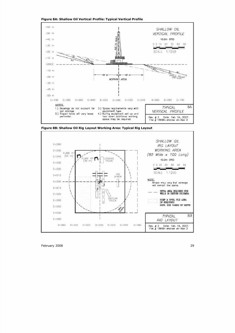
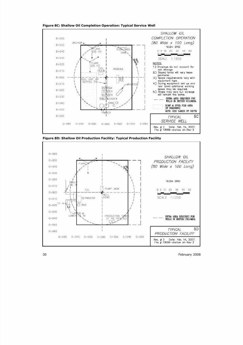
The following templates include a side profile of the lease, as well as templates for
drilling operations, service rig or coil tubing operations, and typical productionrequirements. These templates may be used for wellsite drafting purposes. To
illustrate key issues regarding lease size determination, photographs are included to
help explain the situations encountered.
The following template areas have been developed:
Deep oil operation (Figures:1A, Figures:1B, Figures:1C, Figures:1D )
Deep gas operation (Figure:2A, Figure:2B, Figure:2C , Figure:2D)
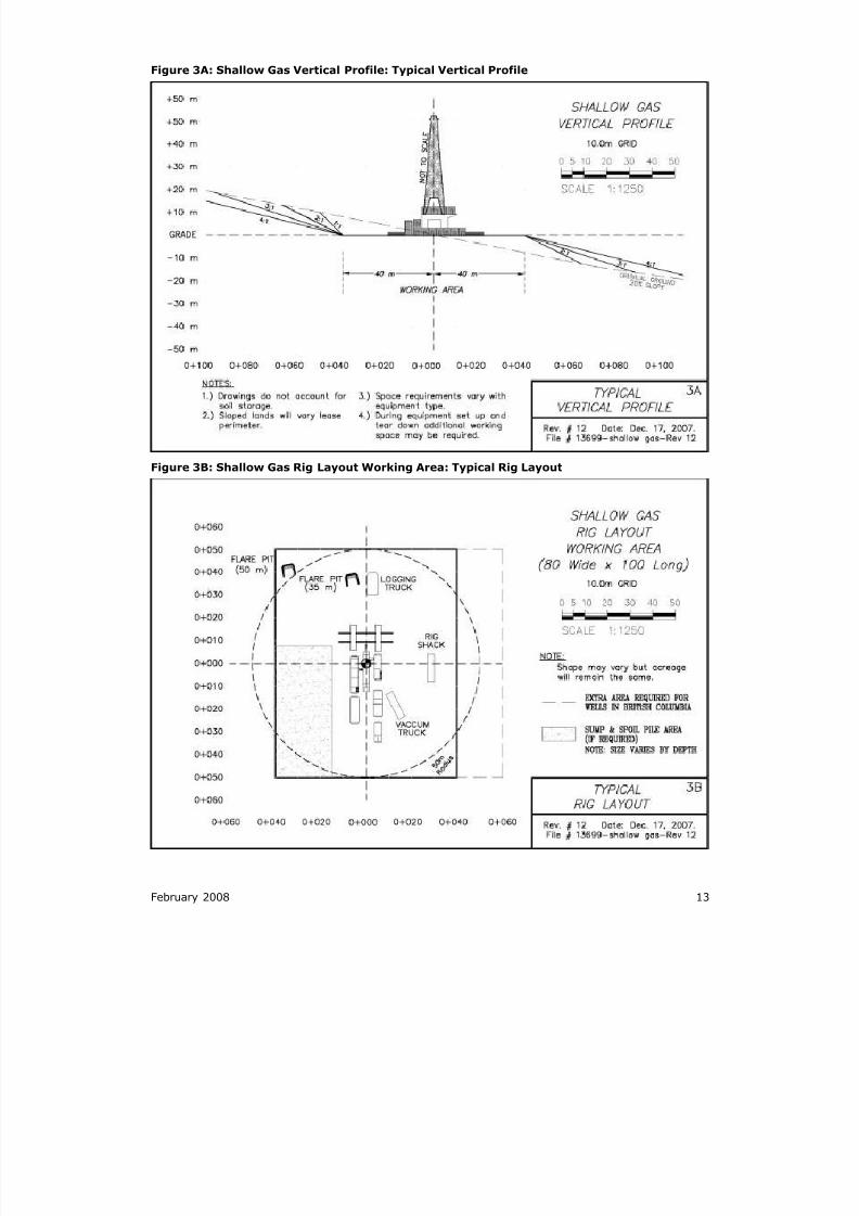
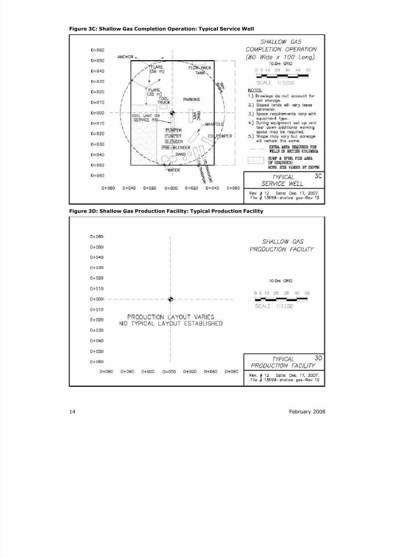
Shallow gas operation (Figure:3A, Figure 3B , Figure:3C , Figure:3D)
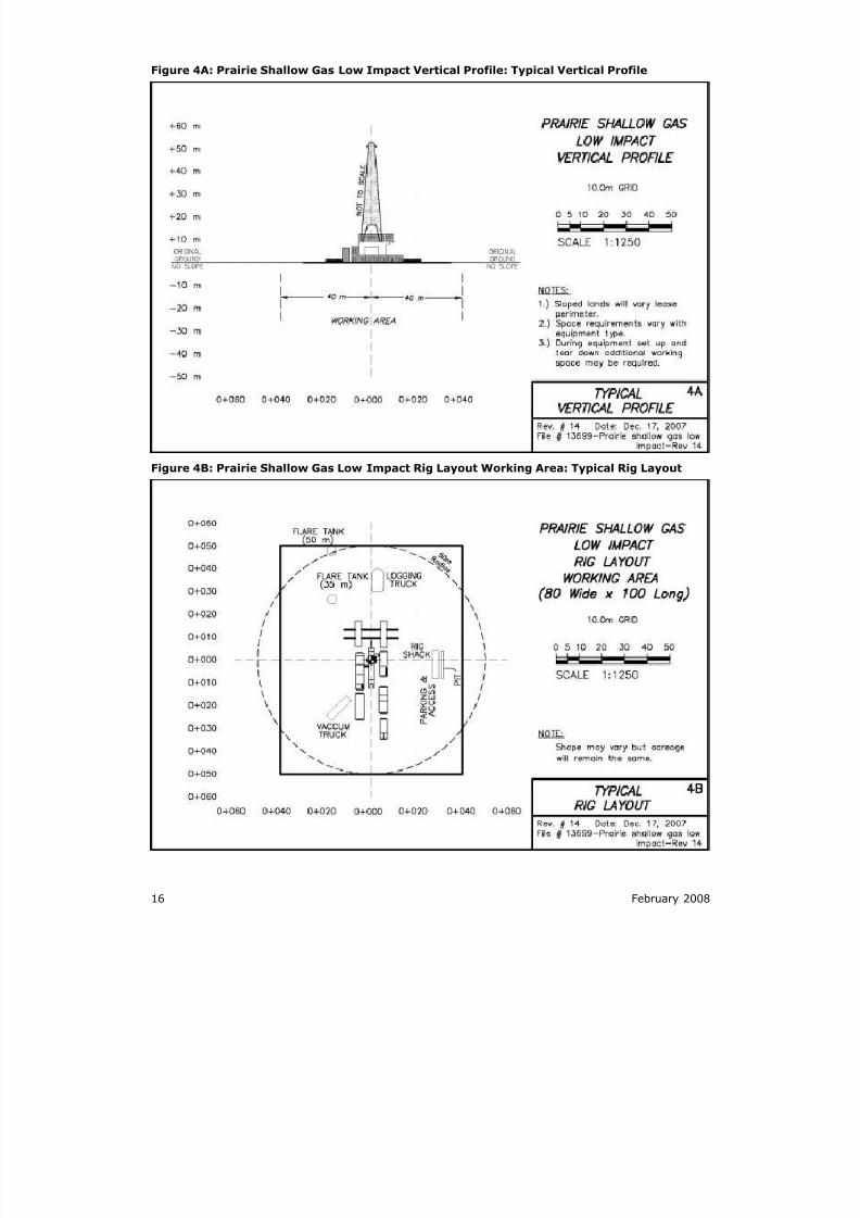
Prairie shallow gas low impact operation (Figure:4A , Figure:4B,
Figure:4C, Figure:4D)
Forested area shallow gas low impact operation (Figure:5A, Figure:5B ,
Figure:5C, Figure:5D)
Shallow gas coil tubing operation (Figure:6A, Figure:6B, Figure:6C,
Figure:6D)
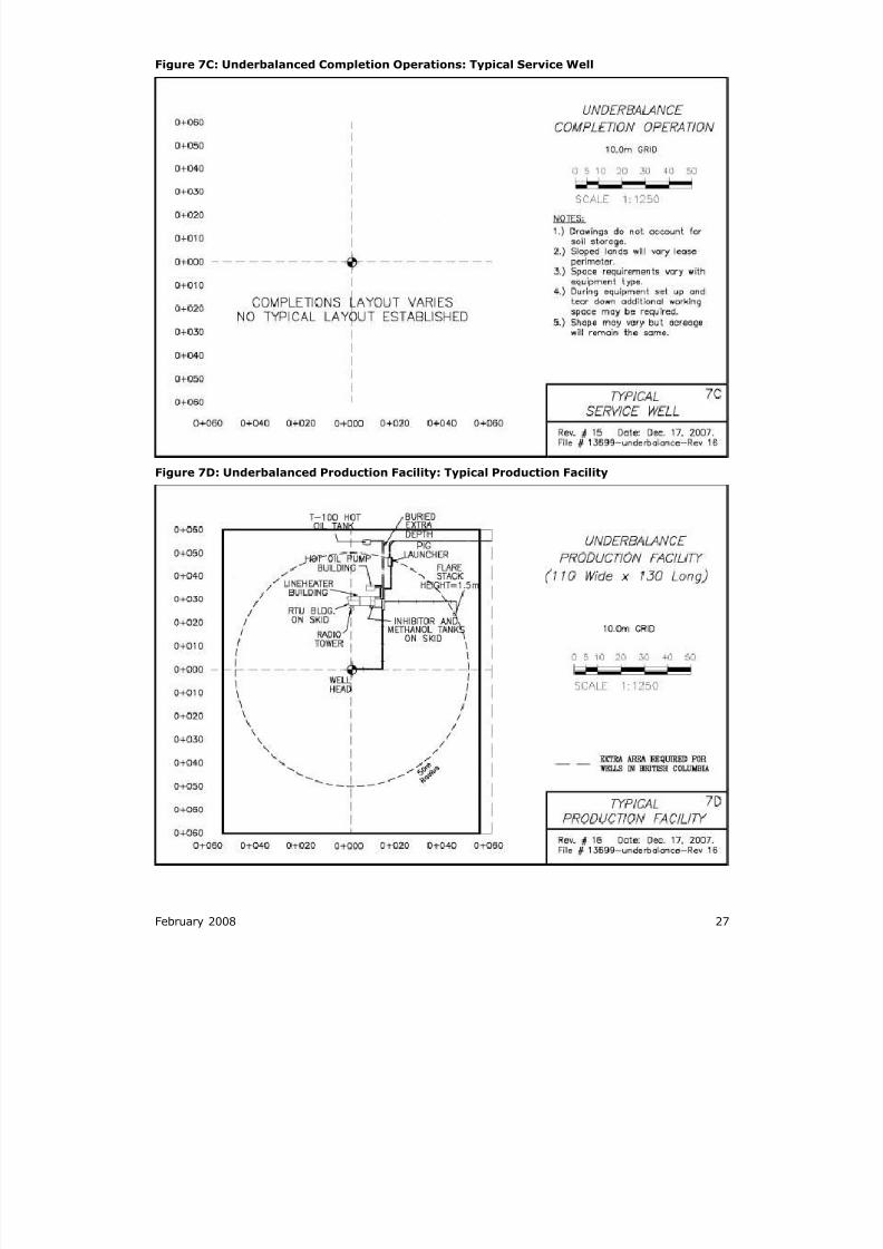
Underbalanced operation (Figure:7A, Figure:7B, Figure:7C, Figure:7D)
Shallow oil operation (Figure:8A, Figure:8B, Figure:8C, Figure:8D)
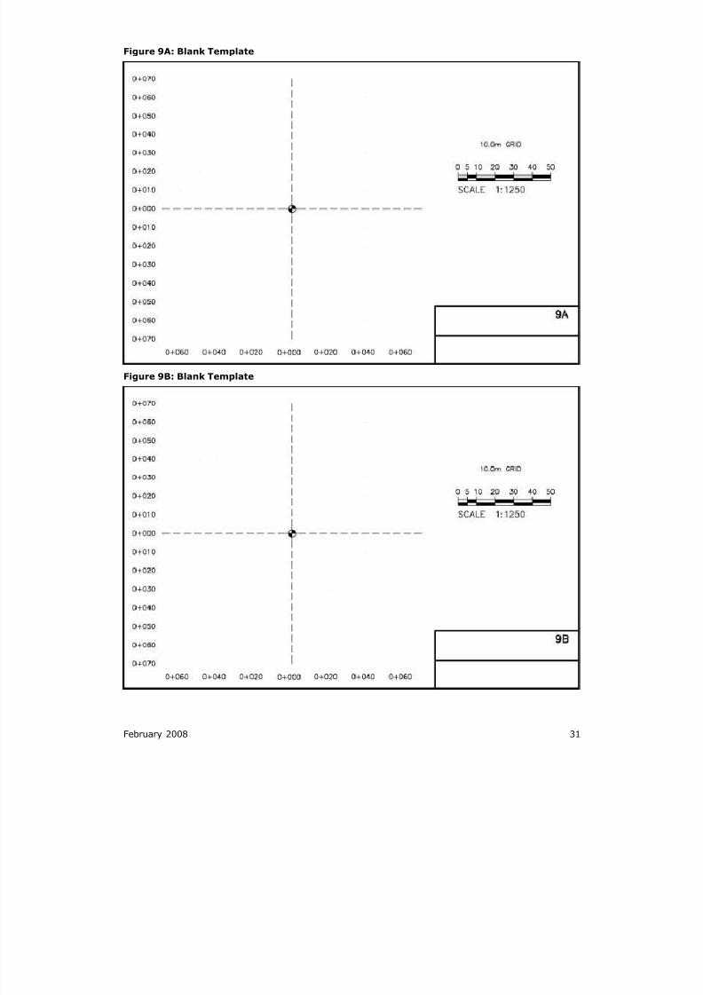
Blank template (Figure:9A, Figure:9B )
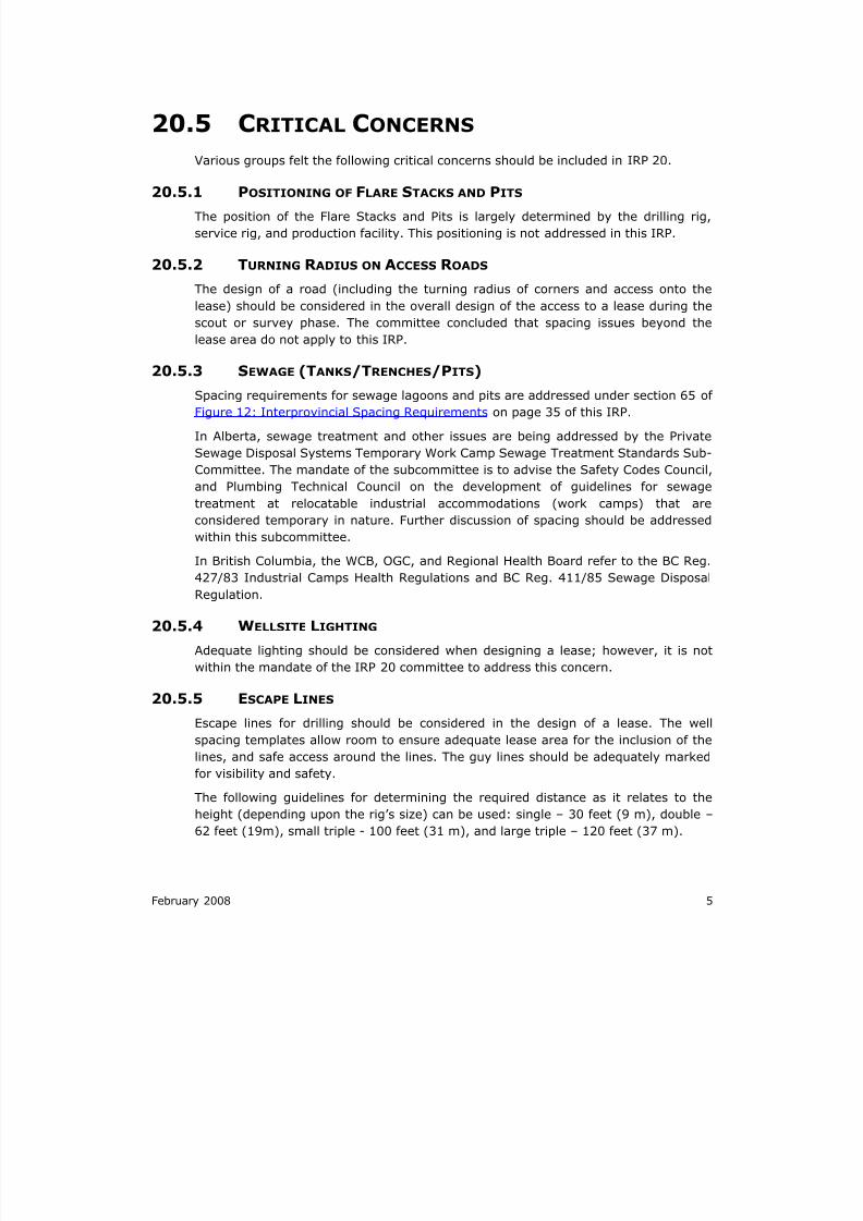
The shallow oil and gas operation formats generally refer to single drill rigs. The
single drill rigs typically drill to a 1,000-metre (3,281-ft.) depth or less, but some are
capable of drilling deeper. The deep oil and gas operation format refers to all other
rigs besides single drill rigs, including triple and double rigs. For most double rigs,
although the drilling rig layout may justify a smaller lease layout, the well servicing
requirements dictate the same spacing as the deep operation formats.
For unique spacing requirements, use of the blank templates is recommended. That
is, they may be used for drafting site-specific situations that are different from the
referenced schematics (e.g., multiwell pads, corehole programs)
8/20/2019 Wellsite Design Spacing Recommendations
http://slidepdf.com/reader/full/wellsite-design-spacing-recommendations 17/61
February 2008 7
Figure 1A: Deep Oil Vertical Profile: Typical Vertical Profile
Figure 1B: Deep Oil Rig Layout Working Area: Typical Rig Layout
8/20/2019 Wellsite Design Spacing Recommendations
http://slidepdf.com/reader/full/wellsite-design-spacing-recommendations 18/61
8 February 2008
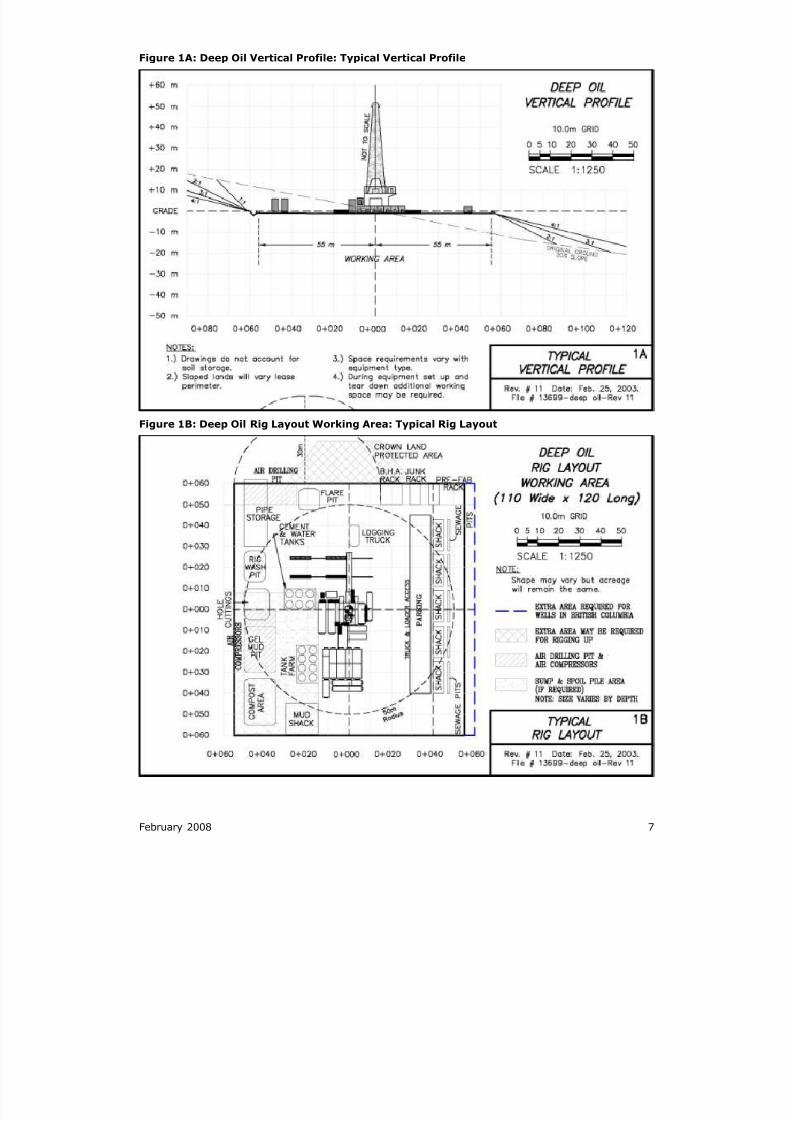
Figure 1C: Deep Oil Completion Operation: Typical Service Well
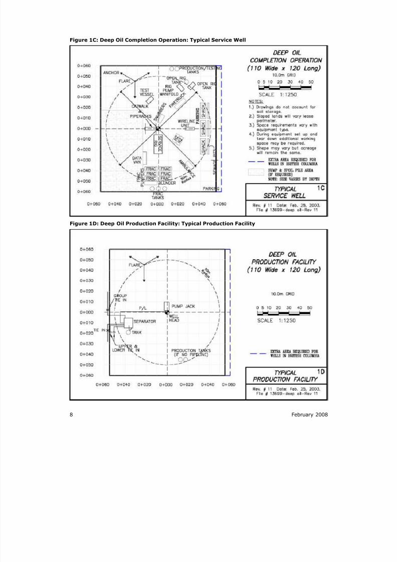
Figure 1D: Deep Oil Production Facility: Typical Production Facility
8/20/2019 Wellsite Design Spacing Recommendations
http://slidepdf.com/reader/full/wellsite-design-spacing-recommendations 19/61
February 2008 9
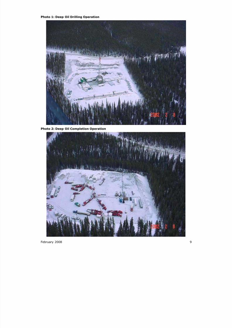
Photo 1: Deep Oil Drilling Operation
Photo 2: Deep Oil Completion Operation
8/20/2019 Wellsite Design Spacing Recommendations
http://slidepdf.com/reader/full/wellsite-design-spacing-recommendations 20/61
10 February 2008
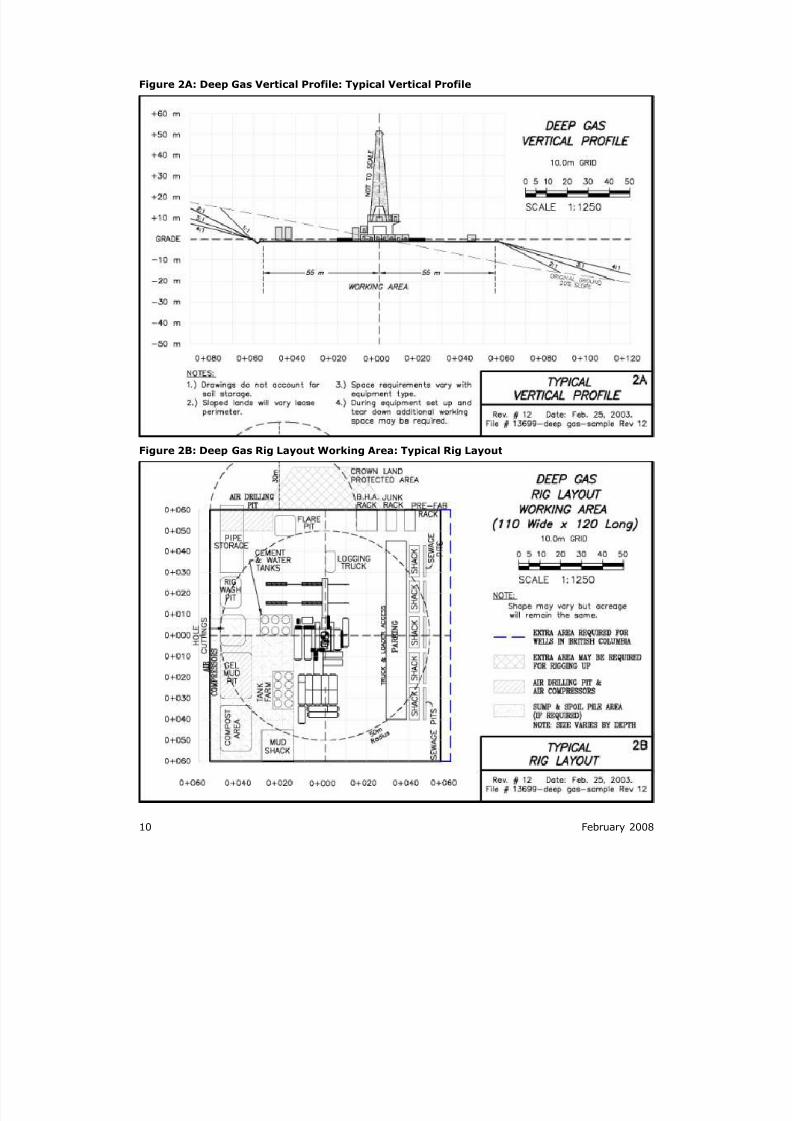
Figure 2A: Deep Gas Vertical Profile: Typical Vertical Profile
Figure 2B: Deep Gas Rig Layout Working Area: Typical Rig Layout
8/20/2019 Wellsite Design Spacing Recommendations
http://slidepdf.com/reader/full/wellsite-design-spacing-recommendations 21/61
February 2008 11
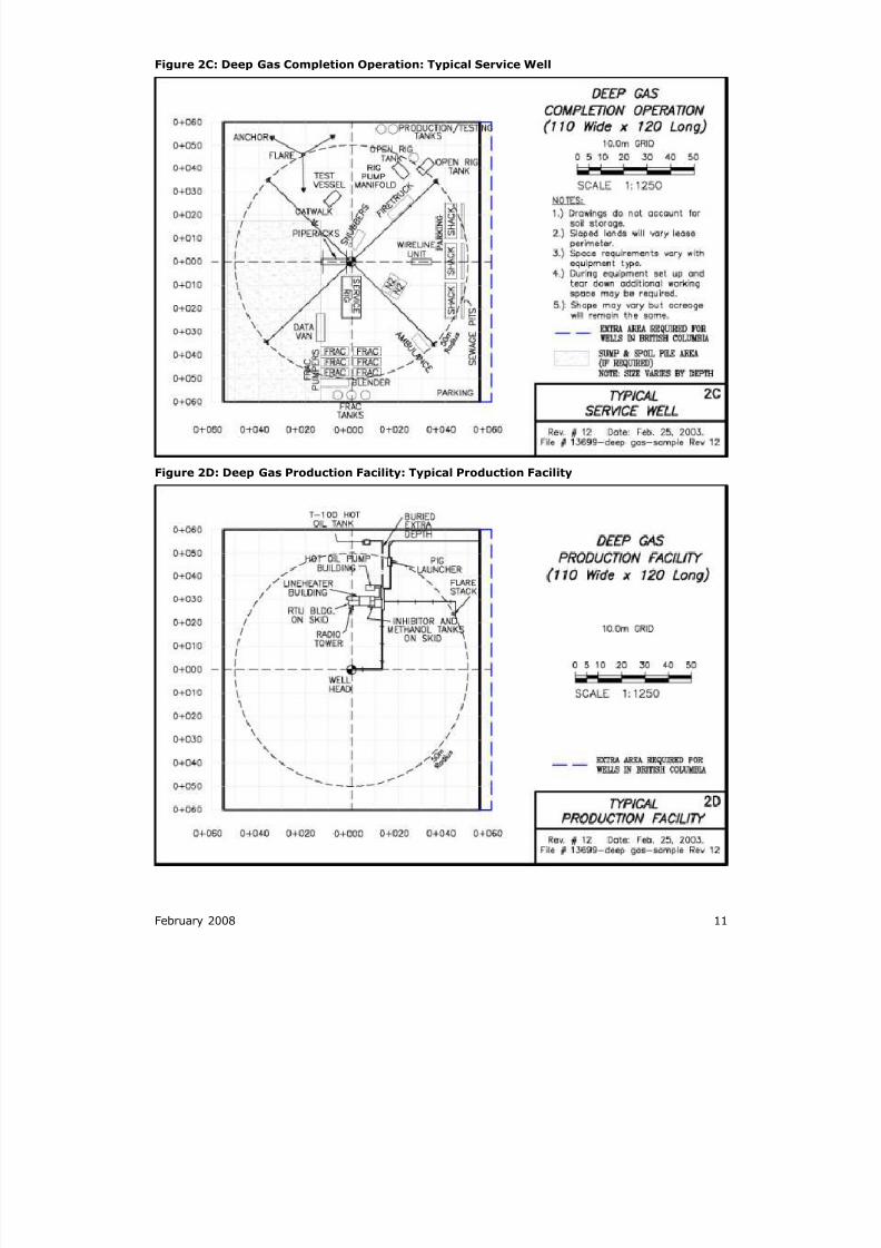
Figure 2C: Deep Gas Completion Operation: Typical Service Well
Figure 2D: Deep Gas Production Facility: Typical Production Facility
8/20/2019 Wellsite Design Spacing Recommendations
http://slidepdf.com/reader/full/wellsite-design-spacing-recommendations 22/61
12 February 2008
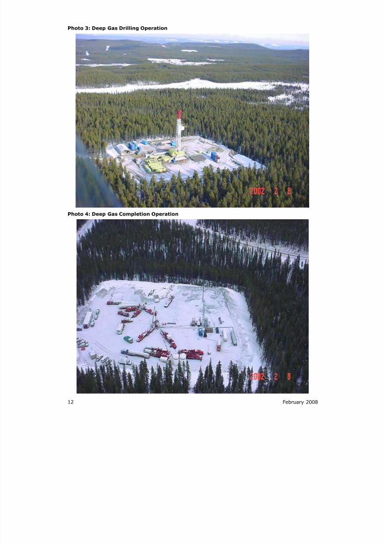
Photo 3: Deep Gas Drilling Operation
Photo 4: Deep Gas Completion Operation
8/20/2019 Wellsite Design Spacing Recommendations
http://slidepdf.com/reader/full/wellsite-design-spacing-recommendations 23/61
February 2008 13
Figure 3A: Shallow Gas Vertical Profile: Typical Vertical Profile
Figure 3B: Shallow Gas Rig Layout Working Area: Typical Rig Layout
8/20/2019 Wellsite Design Spacing Recommendations
http://slidepdf.com/reader/full/wellsite-design-spacing-recommendations 24/61
14 February 2008
Figure 3C: Shallow Gas Completion Operation: Typical Service Well
Figure 3D: Shallow Gas Production Facility: Typical Production Facility
8/20/2019 Wellsite Design Spacing Recommendations
http://slidepdf.com/reader/full/wellsite-design-spacing-recommendations 25/61
February 2008 15
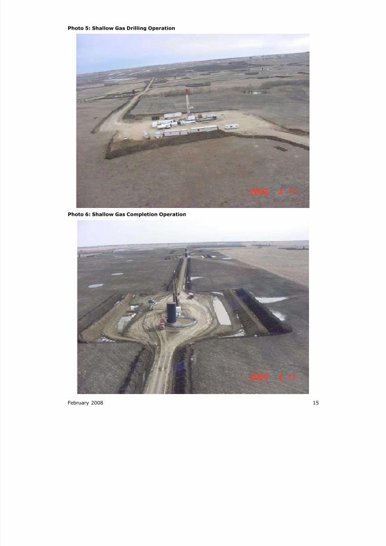
Photo 5: Shallow Gas Drilling Operation
Photo 6: Shallow Gas Completion Operation
8/20/2019 Wellsite Design Spacing Recommendations
http://slidepdf.com/reader/full/wellsite-design-spacing-recommendations 26/61
16 February 2008
Figure 4A: Prairie Shallow Gas Low Impact Vertical Profile: Typical Vertical Profile
Figure 4B: Prairie Shallow Gas Low Impact Rig Layout Working Area: Typical Rig Layout
8/20/2019 Wellsite Design Spacing Recommendations
http://slidepdf.com/reader/full/wellsite-design-spacing-recommendations 27/61
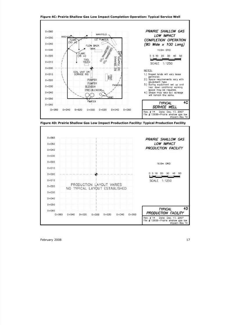
February 2008 17
Figure 4C: Prairie Shallow Gas Low Impact Completion Operation: Typical Service Well
Figure 4D: Prairie Shallow Gas Low Impact Production Facility: Typical Production Facility
8/20/2019 Wellsite Design Spacing Recommendations
http://slidepdf.com/reader/full/wellsite-design-spacing-recommendations 28/61
18 February 2008
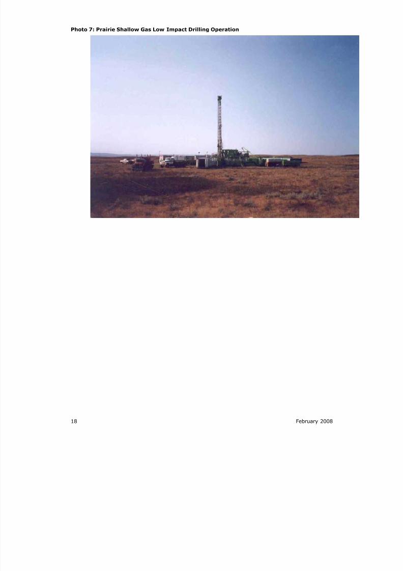
Photo 7: Prairie Shallow Gas Low Impact Drilling Operation
8/20/2019 Wellsite Design Spacing Recommendations
http://slidepdf.com/reader/full/wellsite-design-spacing-recommendations 29/61
February 2008 19
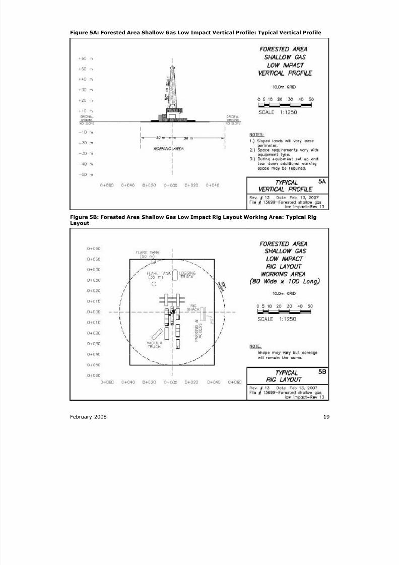
Figure 5A: Forested Area Shallow Gas Low Impact Vertical Profile: Typical Vertical Profile
Figure 5B: Forested Area Shallow Gas Low Impact Rig Layout Working Area: Typical RigLayout
8/20/2019 Wellsite Design Spacing Recommendations
http://slidepdf.com/reader/full/wellsite-design-spacing-recommendations 30/61
20 February 2008
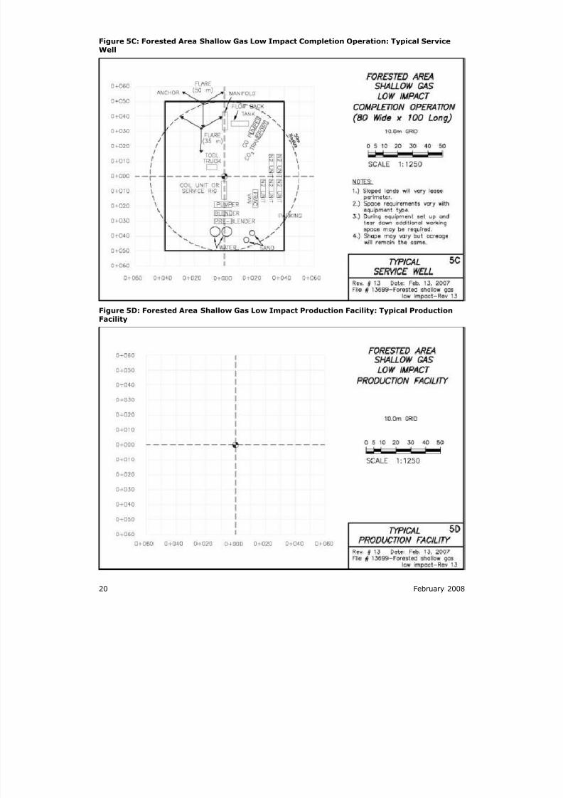
Figure 5C: Forested Area Shallow Gas Low Impact Completion Operation: Typical ServiceWell
Figure 5D: Forested Area Shallow Gas Low Impact Production Facility: Typical ProductionFacility
8/20/2019 Wellsite Design Spacing Recommendations
http://slidepdf.com/reader/full/wellsite-design-spacing-recommendations 31/61
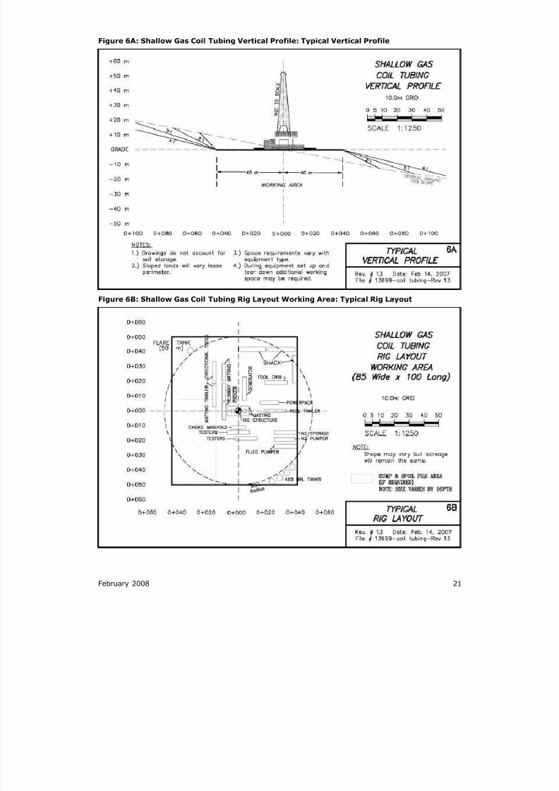
February 2008 21
Figure 6A: Shallow Gas Coil Tubing Vertical Profile: Typical Vertical Profile
Figure 6B: Shallow Gas Coil Tubing Rig Layout Working Area: Typical Rig Layout
8/20/2019 Wellsite Design Spacing Recommendations
http://slidepdf.com/reader/full/wellsite-design-spacing-recommendations 32/61
22 February 2008
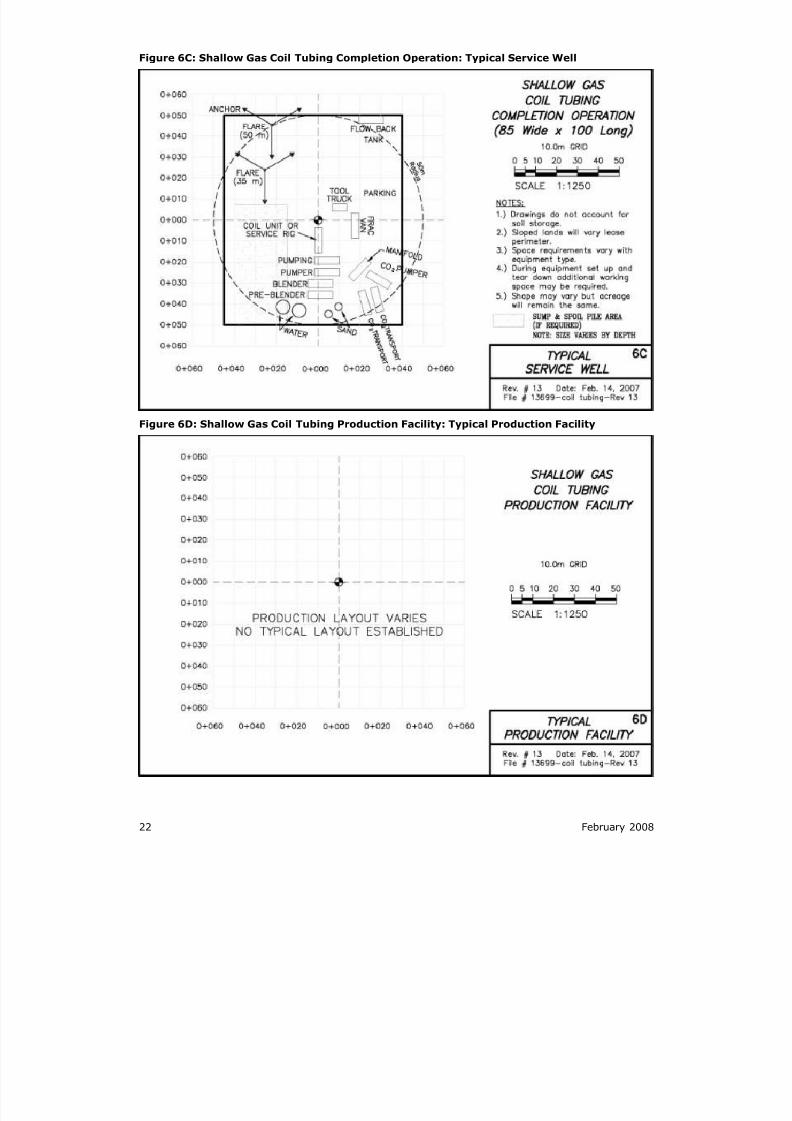
Figure 6C: Shallow Gas Coil Tubing Completion Operation: Typical Service Well
Figure 6D: Shallow Gas Coil Tubing Production Facility: Typical Production Facility
8/20/2019 Wellsite Design Spacing Recommendations
http://slidepdf.com/reader/full/wellsite-design-spacing-recommendations 33/61
February 2008 23
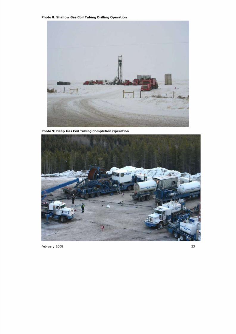
Photo 8: Shallow Gas Coil Tubing Drilling Operation
Photo 9: Deep Gas Coil Tubing Completion Operation
8/20/2019 Wellsite Design Spacing Recommendations
http://slidepdf.com/reader/full/wellsite-design-spacing-recommendations 34/61
24 February 2008
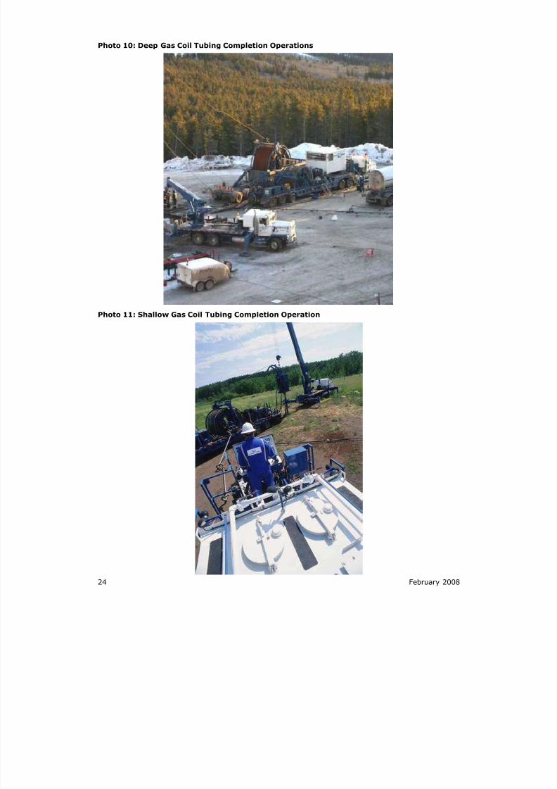
Photo 10: Deep Gas Coil Tubing Completion Operations
Photo 11: Shallow Gas Coil Tubing Completion Operation
8/20/2019 Wellsite Design Spacing Recommendations
http://slidepdf.com/reader/full/wellsite-design-spacing-recommendations 35/61
February 2008 25
Photo 12: Shallow Gas Coil Tubing Completion Operation
8/20/2019 Wellsite Design Spacing Recommendations
http://slidepdf.com/reader/full/wellsite-design-spacing-recommendations 36/61
26 February 2008
Figure 7A: Underbalanced Vertical Profile: Typical Vertical Profile
Figure 7B: Underbalanced Rig Layout Working Area: Typical Rig Layout
8/20/2019 Wellsite Design Spacing Recommendations
http://slidepdf.com/reader/full/wellsite-design-spacing-recommendations 37/61
February 2008 27
Figure 7C: Underbalanced Completion Operations: Typical Service Well
Figure 7D: Underbalanced Production Facility: Typical Production Facility
8/20/2019 Wellsite Design Spacing Recommendations
http://slidepdf.com/reader/full/wellsite-design-spacing-recommendations 38/61
28 February 2008
Photo 13: Underbalanced Completion
8/20/2019 Wellsite Design Spacing Recommendations
http://slidepdf.com/reader/full/wellsite-design-spacing-recommendations 39/61
February 2008 29
Figure 8A: Shallow Oil Vertical Profile: Typical Vertical Profile
Figure 8B: Shallow Oil Rig Layout Working Area: Typical Rig Layout
8/20/2019 Wellsite Design Spacing Recommendations
http://slidepdf.com/reader/full/wellsite-design-spacing-recommendations 40/61
30 February 2008
Figure 8C: Shallow Oil Completion Operation: Typical Service Well
Figure 8D: Shallow Oil Production Facility: Typical Production Facility
8/20/2019 Wellsite Design Spacing Recommendations
http://slidepdf.com/reader/full/wellsite-design-spacing-recommendations 41/61
February 2008 31
Figure 9A: Blank Template
Figure 9B: Blank Template
8/20/2019 Wellsite Design Spacing Recommendations
http://slidepdf.com/reader/full/wellsite-design-spacing-recommendations 42/61
32 February 2008
Photo 14: Corehole Mining Rig
Photo 15: Corehole Single Drilling Rig
8/20/2019 Wellsite Design Spacing Recommendations
http://slidepdf.com/reader/full/wellsite-design-spacing-recommendations 43/61
February 2008 33
Photo 16: Adding Wells to Existing Pads
Photo 17: Many Wells on a Pad Requiring Downhole Avoidance
8/20/2019 Wellsite Design Spacing Recommendations
http://slidepdf.com/reader/full/wellsite-design-spacing-recommendations 44/61
34 February 2008
Photo 18: Screwjacks Instead of Pumpjacks
Photo 19: Vertical Oil Well with Slant Water Wells with Production Facilities
8/20/2019 Wellsite Design Spacing Recommendations
http://slidepdf.com/reader/full/wellsite-design-spacing-recommendations 45/61
February 2008 35
Photo 20: Vertical Oil Well with Slant Oil and Water Wells
Photo 21: Underground Facilities May Impact Well Positioning
8/20/2019 Wellsite Design Spacing Recommendations
http://slidepdf.com/reader/full/wellsite-design-spacing-recommendations 46/61
36 February 2008
Photo 22: Stockpiling to Drill Through the Summer at a Remote Site
Photo 23: Sag D
8/20/2019 Wellsite Design Spacing Recommendations
http://slidepdf.com/reader/full/wellsite-design-spacing-recommendations 47/61
February 2008 37
Photo 24: Rig Moves
Photo 25: Rig Moves
8/20/2019 Wellsite Design Spacing Recommendations
http://slidepdf.com/reader/full/wellsite-design-spacing-recommendations 48/61
38 February 2008
Photo 26: Rig Moves
8/20/2019 Wellsite Design Spacing Recommendations
http://slidepdf.com/reader/full/wellsite-design-spacing-recommendations 49/61
February 2008 33
Figure 10: Sketch Plan: Typical Alberta Flare Pit
8/20/2019 Wellsite Design Spacing Recommendations
http://slidepdf.com/reader/full/wellsite-design-spacing-recommendations 50/61
34 February 2008
Figure 11: Sketch Plan: Typical British Columbia Flare Pit
8/20/2019 Wellsite Design Spacing Recommendations
http://slidepdf.com/reader/full/wellsite-design-spacing-recommendations 51/61
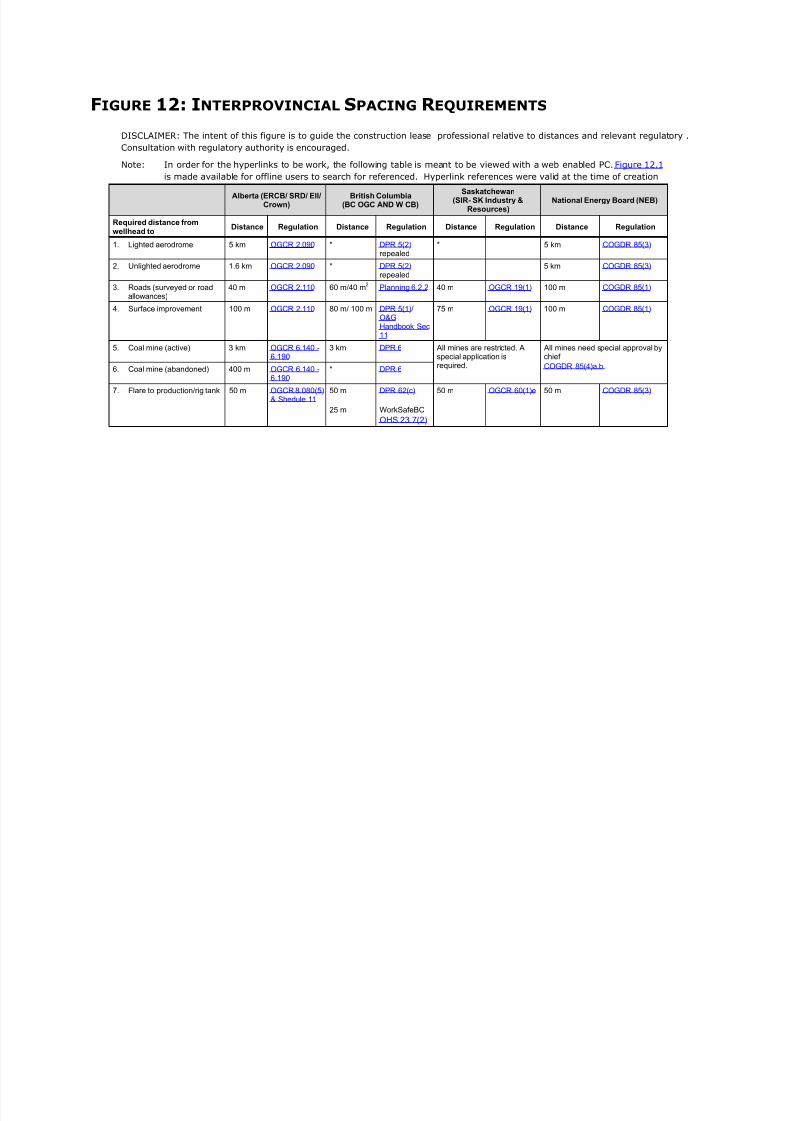
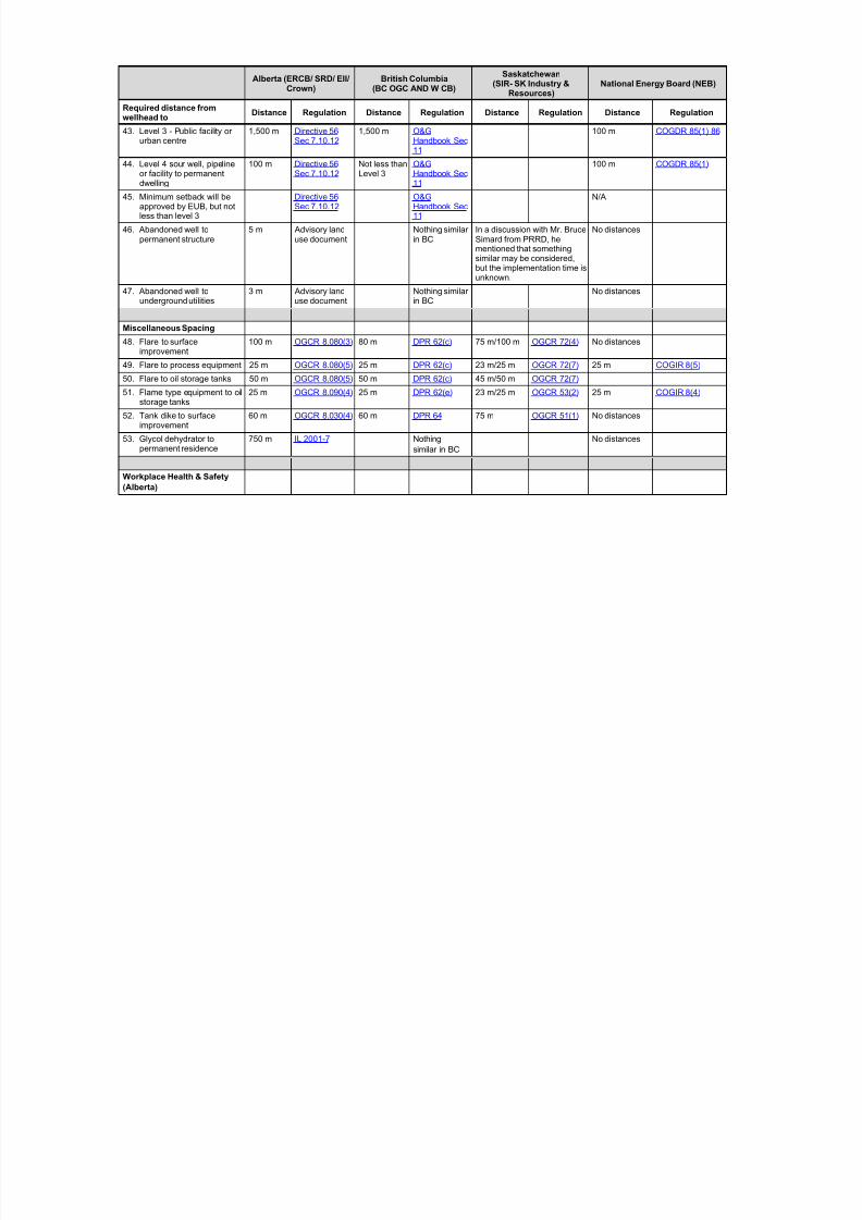
FIGURE 12: INTERPROVINCIAL SPACING R EQUIREMENTS
DISCLAIMER: The intent of this figure is to guide the construction lease professional relative to distances and relevant regulatory .
Consultation with regulatory authority is encouraged.
Note: In order for the hyperlinks to be work, the following table is meant to be viewed with a web enabled PC. Figure 12.1 is made available for offline users to search for referenced. Hyperlink references were valid at the time of creation
Alberta (ERCB/ SRD/ EII/Crown)
British Columbia(BC OGC AND W CB)
Saskatchewan(SIR- SK Industry &
Resources)National Energy Board (NEB)
Required distance fromwellhead to
Distance Regulation Distance Regulation Distance Regulation Distance Regulation
1. Lighted aerodrome 5 km OGCR 2.090 * DPR 5(2) repealed
* 5 km COGDR 85(3)
2. Unlighted aerodrome 1.6 km OGCR 2.090 * DPR 5(2) repealed
5 km COGDR 85(3)
3. Roads (surveyed or roadallowances)
40 m OGCR 2.110 60 m/40 m2 Planning 6.2.2 40 m OGCR 19(1) 100 m COGDR 85(1)
4. Surface improvement 100 m OGCR 2.110 80 m/ 100 m DPR 5(1)/ O&GHandbook Sec
11
75 m OGCR 19(1) 100 m COGDR 85(1)
5. Coal mine (active) 3 km OGCR 6.140 -6.190
3 km DPR 6 All mines are restricted. Aspecial application isrequired.
All mines need special approval bychief
COGDR 85(4)a.b. 6. Coal mine (abandoned) 400 m OGCR 6.140 -6.190
* DPR 6
7. Flare to production/rig tank 50 m OGCR 8.080(5)& Shedule 11
50 m
25 m
DPR 62(c)
WorkSafeBC
OHS 23.7(2)
50 m OGCR 60(1)e 50 m COGDR 85(3)
8/20/2019 Wellsite Design Spacing Recommendations
http://slidepdf.com/reader/full/wellsite-design-spacing-recommendations 52/61
Alberta (ERCB/ SRD/ EII/Crown)
British Columbia(BC OGC AND W CB)
Saskatchewan(SIR- SK Industry &
Resources)National Energy Board (NEB)
Required distance fromwellhead to
Distance Regulation Distance Regulation Distance Regulation Distance Regulation
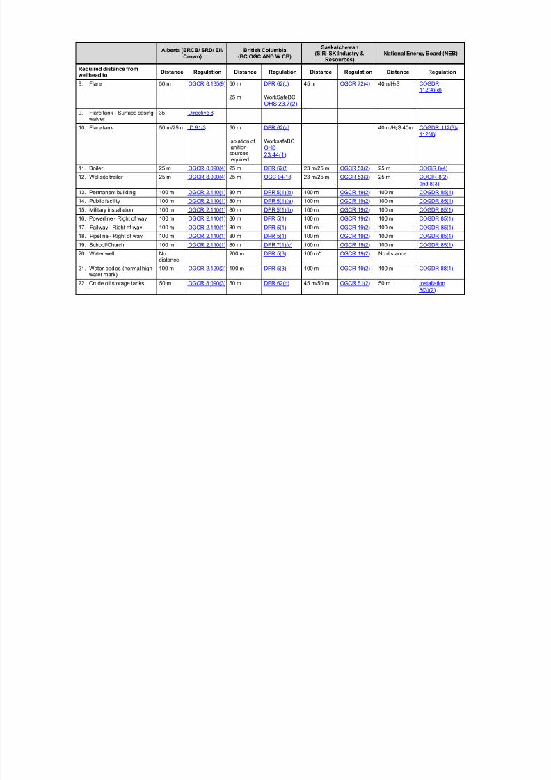
8. Flare 50 m OGCR 8.135(9) 50 m
25 m
DPR 62(c)
WorkSafeBC
OHS 23.7(2)
45 m OGCR 72(4) 40m/H2S COGDR112(4)(d)i
9. Flare tank - Surface casingwaiver
35 Directive 8
10. Flare tank 50 m/25 m ID 91-3 50 m
Isolation ofIgnitionsourcesrequired
DPR 62(a)
WorksafeBC
OHS
23.44(1)
40 m/H2S 40m COGDR 112(3)a
112(4)i
11. Boiler 25 m OGCR 8.090(4) 25 m DPR 62(f) 23 m/25 m OGCR 53(2) 25 m COGiR 8(4)
12. Wellsite trailer 25 m OGCR 8.090(4) 25 m OGC 04-18 23 m/25 m OGCR 53(3) 25 m COGIR 8(2)
and 8(3)
13. Permanent building 100 m OGCR 2.110(1) 80 m DPR 5(1)(b) 100 m OGCR 19(2) 100 m COGDR 85(1)
14. Public facility 100 m OGCR 2.110(1) 80 m DPR 5(1)(a) 100 m OGCR 19(2) 100 m COGDR 85(1)
15. Military installation 100 m OGCR 2.110(1) 80 m DPR 5(1)(b) 100 m OGCR 19(2) 100 m COGDR 85(1)
16. Powerline - Right of way 100 m OGCR 2.110(1) 80 m DPR 5(1) 100 m OGCR 19(2) 100 m COGDR 85(1)
17. Railway - Right of way 100 m OGCR 2.110(1) 80 m DPR 5(1) 100 m OGCR 19(2) 100 m COGDR 85(1)
18. Pipeline - Right of way 100 m OGCR 2.110(1) 80 m DPR 5(1) 100 m OGCR 19(2) 100 m COGDR 85(1)
19. School/Church 100 m OGCR 2.110(1) 80 m DPR 7(1)(c) 100 m OGCR 19(2) 100 m COGDR 85(1)
20. Water well Nodistance
200 m DPR 5(3) 100 m* OGCR 19(2) No distance
21. Water bodies (normal highwater mark)
100 m OGCR 2.120(2) 100 m DPR 5(3) 100 m OGCR 19(2) 100 m COGDR 88(1)
22. Crude oil storage tanks 50 m OGCR 8.090(3) 50 m DPR 62(h) 45 m/50 m OGCR 51(2) 50 m Installation
8(3)(2)
8/20/2019 Wellsite Design Spacing Recommendations
http://slidepdf.com/reader/full/wellsite-design-spacing-recommendations 53/61
Alberta (ERCB/ SRD/ EII/Crown)
British Columbia(BC OGC AND W CB)
Saskatchewan(SIR- SK Industry &
Resources)National Energy Board (NEB)
Required distance fromwellhead to
Distance Regulation Distance Regulation Distance Regulation Distance Regulation
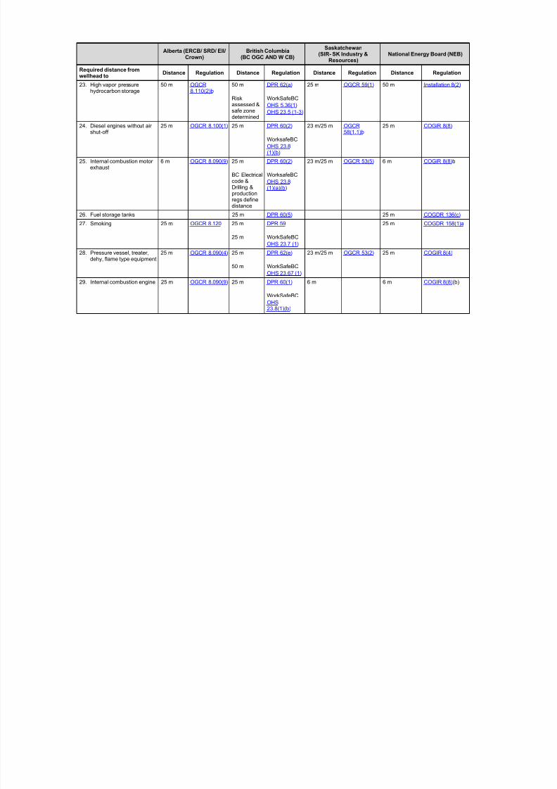
23. High vapor pressurehydrocarbon storage
50 m OGCR8.110(2)b
50 m
Riskassessed &safe zone
determined
DPR 62(a)
WorkSafeBC
OHS 5.36(1)
OHS 23.5 (1-3)
25 m OGCR 59(1) 50 m Installation 8(2)
24. Diesel engines without airshut-off
25 m OGCR 8.100(1) 25 m DPR 60(2)
WorksafeBC
OHS 23.8(1)(b)
23 m/25 m OGCR58(1.1)b
25 m COGiR 8(8)
25. Internal combustion motorexhaust
6 m OGCR 8.090(9) 25 m
BC Electricalcode &Drilling &productionregs definedistance
DPR 60(2)
WorksafeBC
OHS 23.8(1)(a)(b)
23 m/25 m OGCR 53(5) 6 m COGiR 8(8)b
26. Fuel storage tanks 25 m DPR 60(5) 25 m COGDR 136(c)
27. Smoking 25 m OGCR 8.120 25 m
25 m
DPR 59
WorkSafeBCOHS 23.7 (1)
25 m COGDR 158(1)a
28. Pressure vessel, treater,dehy, flame type equipment
25 m OGCR 8.090(4) 25 m
50 m
DPR 62(e)
WorkSafeBC
OHS 23.67 (1)
23 m/25 m OGCR 53(2) 25 m COGIR 8(4)
29. Internal combustion engine 25 m OGCR 8.090(9) 25 m DPR 60(1)
WorkSafeBC
OHS23.8(1)(b)
6 m 6 m COGIR 8(8)(b)
8/20/2019 Wellsite Design Spacing Recommendations
http://slidepdf.com/reader/full/wellsite-design-spacing-recommendations 54/61
Alberta (ERCB/ SRD/ EII/Crown)
British Columbia(BC OGC AND W CB)
Saskatchewan(SIR- SK Industry &
Resources)National Energy Board (NEB)
Required distance fromwellhead to
Distance Regulation Distance Regulation Distance Regulation Distance Regulation
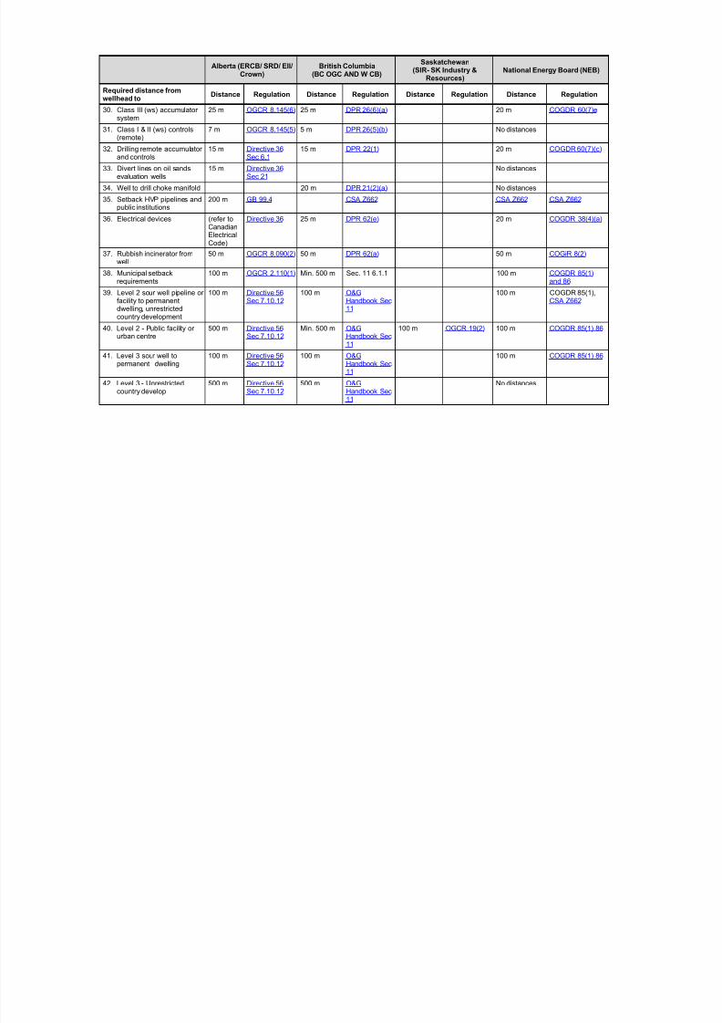
30. Class III (ws) accumulatorsystem
25 m OGCR 8.145(6) 25 m DPR 26(6)(a) 20 m COGDR 60(7)e
31. Class I & II (ws) controls(remote)
7 m OGCR 8.145(5) 5 m DPR 26(5)(b) No distances
32. Drilling remote accumulatorand controls
15 m Directive 36Sec 6.1
15 m DPR 22(1) 20 m COGDR 60(7)(c)
33. Divert lines on oil sandsevaluation wells
15 m Directive 36Sec 21
No distances
34. Well to drill choke manifold 20 m DPR 21(2)(a) No distances
35. Setback HVP pipelines andpublic institutions
200 m GB 99.4 CSA Z662 CSA Z662 CSA Z662
36. Electrical devices (refer toCanadianElectricalCode)
Directive 36 25 m DPR 62(e) 20 m COGDR 38(4)(a)
37. Rubbish incinerator fromwell
50 m OGCR 8.090(2) 50 m DPR 62(a) 50 m COGiR 8(2)
38. Municipal setbackrequirements
100 m OGCR 2.110(1) Min. 500 m Sec. 11 6.1.1 100 m COGDR 85(1)and 86
39. Level 2 sour well pipeline orfacility to permanentdwelling, unrestrictedcountry development
100 m Directive 56Sec 7.10.12
100 m O&GHandbook Sec11
100 m COGDR 85(1),CSA Z662
40. Level 2 - Public facility orurban centre
500 m Directive 56Sec 7.10.12
Min. 500 m O&GHandbook Sec11
100 m OGCR 19(2) 100 m COGDR 85(1) 86
41. Level 3 sour well topermanent dwelling
100 m Directive 56Sec 7.10.12
100 m O&GHandbook Sec11
100 m COGDR 85(1) 86
42. Level 3 - Unrestrictedcountry develop
500 m Directive 56Sec 7.10.12
500 m O&GHandbook Sec11
No distances
8/20/2019 Wellsite Design Spacing Recommendations
http://slidepdf.com/reader/full/wellsite-design-spacing-recommendations 55/61
Alberta (ERCB/ SRD/ EII/Crown)
British Columbia(BC OGC AND W CB)
Saskatchewan(SIR- SK Industry &
Resources)National Energy Board (NEB)
Required distance fromwellhead to
Distance Regulation Distance Regulation Distance Regulation Distance Regulation
43. Level 3 - Public facility orurban centre
1,500 m Directive 56Sec 7.10.12
1,500 m O&GHandbook Sec11
100 m COGDR 85(1) 86
44. Level 4 sour well, pipelineor facility to permanent
dwelling
100 m Directive 56Sec 7.10.12
Not less thanLevel 3
O&GHandbook Sec
11
100 m COGDR 85(1)
45. Minimum setback will beapproved by EUB, but notless than level 3
Directive 56Sec 7.10.12
O&GHandbook Sec11
N/A
46. Abandoned well topermanent structure
5 m Advisory landuse document
Nothing similarin BC
In a discussion with Mr. BruceSimard from PRRD, hementioned that somethingsimilar may be considered,but the implementation time isunknown.
No distances
47. Abandoned well tounderground utilities
3 m Advisory landuse document
Nothing similarin BC
No distances
Miscellaneous Spacing
48. Flare to surfaceimprovement
100 m OGCR 8.080(3) 80 m DPR 62(c) 75 m/100 m OGCR 72(4) No distances
49. Flare to process equipment 25 m OGCR 8.080(5) 25 m DPR 62(c) 23 m/25 m OGCR 72(7) 25 m COGIR 8(5)
50. Flare to oil storage tanks 50 m OGCR 8.080(5) 50 m DPR 62(c) 45 m/50 m OGCR 72(7)
51. Flame type equipment to oilstorage tanks
25 m OGCR 8.090(4) 25 m DPR 62(e) 23 m/25 m OGCR 53(2) 25 m COGIR 8(4)
52. Tank dike to surfaceimprovement
60 m OGCR 8.030(4) 60 m DPR 64 75 m OGCR 51(1) No distances
53. Glycol dehydrator topermanent residence
750 m IL 2001-7 Nothing
similar in BC
No distances
Workplace Health & Safety
(Alberta)
8/20/2019 Wellsite Design Spacing Recommendations
http://slidepdf.com/reader/full/wellsite-design-spacing-recommendations 56/61
Alberta (ERCB/ SRD/ EII/Crown)
British Columbia(BC OGC AND W CB)
Saskatchewan(SIR- SK Industry &
Resources)National Energy Board (NEB)
Required distance fromwellhead to
Distance Regulation Distance Regulation Distance Regulation Distance Regulation
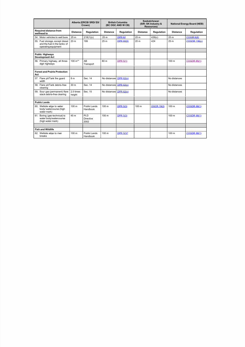
54. Motor vehicles to well bore 25 m 218(1)(c) 25 m DPR 62 25 m 439(c) 25 m COGIR 8(8)
55. Fuel storage, except dieseland the fuel in the tanks ofoperating equipment
20 m 199 25 m DPR 60(5) 20 m 424 25 m COGDR 136(c)
Public HighwaysDevelopment Act
56. Primary highway, all three-digit highways
100 m** AB
Transport
80 m DPR 5(1) 100 m COGDR 85(1)
Forest and Prairie ProtectionAct
57. Flare pit/Tank fire guardwidth
8 m Sec. 14 No distances DPR 62(n) No distances
58. Flare pit/Tank debris-freeclearing
30 m Sec. 14 No distances DPR 62(n) No distances
59. Sour gas (permanent) flarestack debris-free clearing
2.5 times
height
Sec. 15 No distances DPR 62(n) No distances
Public Lands
60. Wellsite edge to waterbody/ watercourse (highwater mark)
100 m Public Lands
Handbook
100 m DPR 5(3) 100 m OGCR 19(2) 100 m COGDR 88(1)
61. Boring (geo-technical) towater body/watercourse(high water mark)
45 m PLD
Directive
2002
100 m DPR 5(3) 100 m COGDR 88(1)
Fish and Wildlife
62. Wellsite edge to riverbreaks
100 m Public Lands
Handbook
100 m DPR 5(3)* 100 m COGDR 88(1)
8/20/2019 Wellsite Design Spacing Recommendations
http://slidepdf.com/reader/full/wellsite-design-spacing-recommendations 57/61
Alberta (ERCB/ SRD/ EII/Crown)
British Columbia(BC OGC AND W CB)
Saskatchewan(SIR- SK Industry &
Resources)National Energy Board (NEB)
Required distance fromwellhead to
Distance Regulation Distance Regulation Distance Regulation Distance Regulation
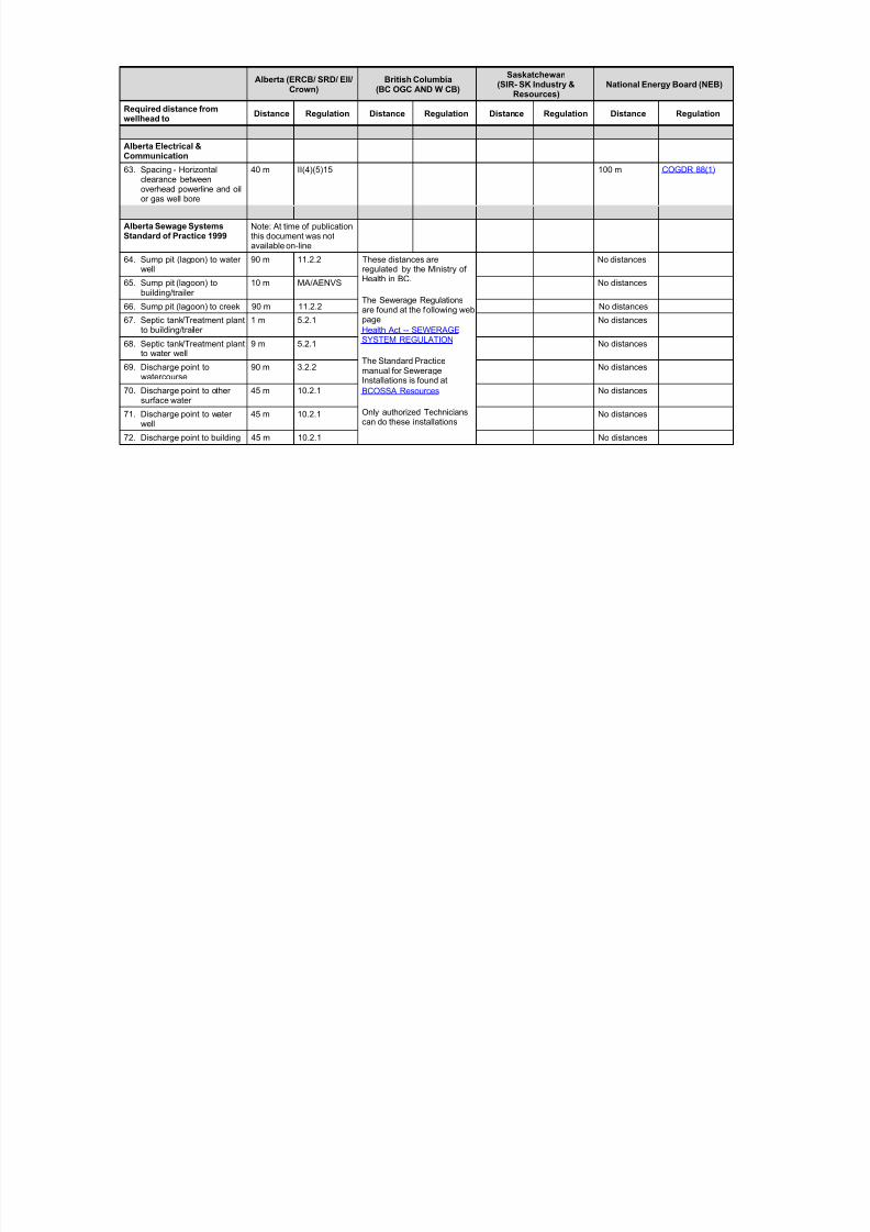
Alberta Electrical &Communication
63. Spacing - Horizontalclearance betweenoverhead powerline and oilor gas well bore
40 m II(4)(5)15 100 m COGDR 88(1)
Alberta Sewage SystemsStandard of Practice 1999
Note: At time of publicationthis document was notavailable on-line
64. Sump pit (lagoon) to waterwell
90 m 11.2.2 These distances areregulated by the Ministry ofHealth in BC.
The Sewerage Regulationsare found at the following webpage
Health Act -- SEWERAGESYSTEM REGULATION
The Standard Practice
manual for SewerageInstallations is found at
BCOSSA Resources
Only authorized Technicianscan do these installations
No distances
65. Sump pit (lagoon) tobuilding/trailer
10 m MA/AENVS No distances
66. Sump pit (lagoon) to creek 90 m 11.2.2 No distances
67. Septic tank/Treatment plantto building/trailer
1 m 5.2.1 No distances
68. Septic tank/Treatment plantto water well
9 m 5.2.1 No distances
69. Discharge point towatercourse
90 m 3.2.2 No distances
70. Discharge point to othersurface water
45 m 10.2.1 No distances
71. Discharge point to waterwell
45 m 10.2.1 No distances
72. Discharge point to building 45 m 10.2.1 No distances

8/20/2019 Wellsite Design Spacing Recommendations
http://slidepdf.com/reader/full/wellsite-design-spacing-recommendations 58/61
*Additional setback restrictions may be dictated by other regulatory authorities*H2S release rates may increase setback spacing requirements*Refer to specific regulations for exceptions.**Authorization required within 100 m1In Drilling and Production Regulation, it is not specified if this distance is referring to sweet or sour gas.
2Variance if it is your own road
Additional Notes:BC OHS 4.1 - General Conditions and OHS 23.5 (1-3) would allow enforcement of other legislation relating to spacing requirements if it is viewed that thehealth and safety of workers at the jobsite is being, or could be, negatively impacted by the layout of the well site
8/20/2019 Wellsite Design Spacing Recommendations
http://slidepdf.com/reader/full/wellsite-design-spacing-recommendations 59/61
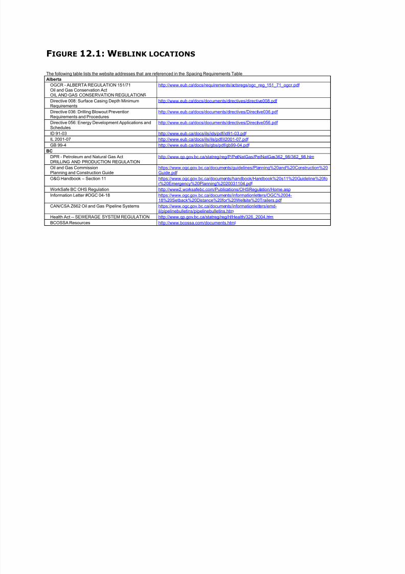
FIGURE 12.1: WEBLINK LOCATIONS
The following table lists the website addresses that are referenced in the Spacing Requirements Table
Alberta
OGCR - ALBERTA REGULATION 151/71Oil and Gas Conservation ActOIL AND GAS CONSERVATION REGULATIONS
http://www.eub.ca/docs/requirements/actsregs/ogc_reg_151_71_ogcr.pdf
Directive 008: Surface Casing Depth MinimumRequirements
http://www.eub.ca/docs/documents/directives/directive008.pdf
Directive 036: Drilling Blowout PreventionRequirements and Procedures
http://www.eub.ca/docs/documents/directives/Directive036.pdf
Directive 056: Energy Development Applications andSchedules
http://www.eub.ca/docs/documents/directives/Directive056.pdf
ID 91-03 http://www.eub.ca/docs/ils/ids/pdf/id91-03.pdf
IL 2001-07 http://www.eub.ca/docs/ils/ils/pdf/il2001-07.pdf
GB 99-4 http://www.eub.ca/docs/ils/gbs/pdf/gb99-04.pdf
BC
DPR - Petroleum and Natural Gas ActDRILLING AND PRODUCTION REGULATION
http://www.qp.gov.bc.ca/statreg/reg/P/PetNatGas/PetNatGas362_98/362_98.htm
Oil and Gas Commission
Planning and Construction Guide
https://www.ogc.gov.bc.ca/documents/guidelines/Planning%20and%20Construction%20
Guide.pdf
O&G Handbook – Section 11 https://www.ogc.gov.bc.ca/documents/handbook/Handbook%20s11%20Guideline%20for%20Emergency%20Planning%2020031104.pdf
WorkSafe BC OHS Regulation http://www2.worksafebc.com/Publications/OHSRegulation/Home.asp
Information Letter #OGC 04-18 https://www.ogc.gov.bc.ca/documents/informationletters/OGC%2004-18%20Setback%20Distance%20for%20Wellsite%20Trailers.pdf
CAN/CSA Z662 Oil and Gas Pipeline Systems https://www.ogc.gov.bc.ca/documents/informationletters/emd-il/pipelinebulletins/pipelinebulletins.htm
Health Act -- SEWERAGE SYSTEM REGULATION http://www.qp.gov.bc.ca/statreg/reg/H/Health/326_2004.htm
BCOSSA Resources http://www.bcossa.com/documents.html

8/20/2019 Wellsite Design Spacing Recommendations
http://slidepdf.com/reader/full/wellsite-design-spacing-recommendations 60/61
Saskatchewan
OGCR – The Oil and Gas Conservation Regulations http://www.qp.gov.sk.ca/documents/English/Regulations/Regulations/O2R1.pdf
National Energy Board
Canada Oil and Gas Drilling Regulations http://laws.justice.gc.ca/en/ShowTdm/cr/SOR-79-82//en/en
Installation - Canada Oil and Gas InstallationsRegulations (SOR/96-118)
http://laws.justice.gc.ca/en/ShowTdm/cr/SOR-96-118//en/en
8/20/2019 Wellsite Design Spacing Recommendations
http://slidepdf.com/reader/full/wellsite-design-spacing-recommendations 61/61
Wellsite Design Spacing Recommendations IRP20 FINAL to post
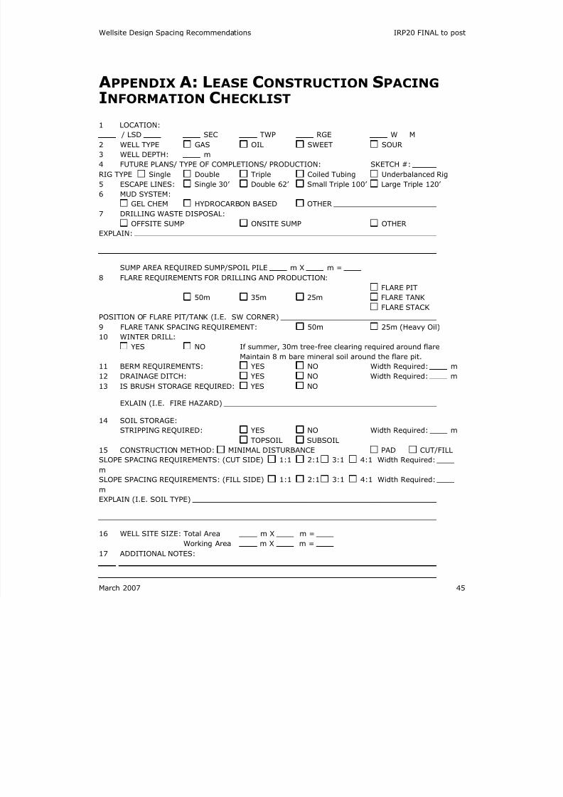
APPENDIX A: LEASE CONSTRUCTION SPACING
INFORMATION CHECKLIST
1 LOCATION:
/ LSD SEC TWP RGE W M
2 WELL TYPE GAS OIL SWEET SOUR
3 WELL DEPTH: m
4 FUTURE PLANS/ TYPE OF COMPLETIONS/ PRODUCTION: SKETCH #:
RIG TYPE Single Double Triple Coiled Tubing Underbalanced Rig
5 ESCAPE LINES: Single 30’ Double 62’ Small Triple 100’ Large Triple 120’
6 MUD SYSTEM:
GEL CHEM HYDROCARBON BASED OTHER
7 DRILLING WASTE DISPOSAL:
OFFSITE SUMP ONSITE SUMP OTHER
EXPLAIN:
SUMP AREA REQUIRED SUMP/SPOIL PILE m X m =
8 FLARE REQUIREMENTS FOR DRILLING AND PRODUCTION:
FLARE PIT
50m 35m 25m FLARE TANK
FLARE STACK
POSITION OF FLARE PIT/TANK (I.E. SW CORNER)
9 FLARE TANK SPACING REQUIREMENT: 50m 25m (Heavy Oil)
10 WINTER DRILL:
YES NO If summer, 30m tree-free clearing required around flare
Maintain 8 m bare mineral soil around the flare pit.11 BERM REQUIREMENTS: YES NO Width Required: m
12 DRAINAGE DITCH: YES NO Width Required: m
13 IS BRUSH STORAGE REQUIRED: YES NO
EXLAIN (I.E. FIRE HAZARD)
14 SOIL STORAGE:
STRIPPING REQUIRED: YES NO Width Required: m
TOPSOIL SUBSOIL
15 CONSTRUCTION METHOD: MINIMAL DISTURBANCE PAD CUT/FILL
SLOPE SPACING REQUIREMENTS: (CUT SIDE) 1:1 2:1 3:1 4:1 Width Required:
m
SLOPE SPACING REQUIREMENTS: (FILL SIDE) 1:1 2:1 3:1 4:1 Width Required:m
EXPLAIN (I.E. SOIL TYPE)


