9
1 WELMEC 8.14 Issue 1 WELMEC European cooperation in legal metrology November 2006

1
WELMEC 8.14 Issue 1
WELMEC European cooperation in legal metrology
November 2006
2
WELMEC European cooperation in legal metrology
WELMEC is a cooperation between the legal metrology services of the Member States of the European Union and EFTA. This document is one of a number of Guides published by WELMEC to provide guidance to manufacturers of measuring instruments and to notified bodies responsible for conformity assessment of their products. The Guides are purely advisory and do not themselves impose any restrictions or additional technical requirements beyond those contained in relevant EC Directives. Alternative approaches may be acceptable, but the guidance provided in this document represents the considered view of WELMEC as to the best practice to be followed.
Published by: WELMEC Secretariat Email : [email protected] Website: www.welmec.org
WELMEC WG 11
3
FOREWORD
The Measuring Instruments Directive (MID) 2004/22/EC entered into force on the 30th October 2006. In this new approach directive the presumption of conformity is mentioned in Article 13. In addition to the use of harmonised standards (Art. 13 point 1) a new route is open for the presumption of conformity by using OIML recommendations (Art. 13 point 2).
“Member States shall presume conformity with the essential requirements referred to in Annex I and in the relevant instrument-specific Annexes in respect of a measuring instruments that complies with the corresponding parts of the normative documents and lists referred to in Article 16(1)(a), the references in respect of which have been published in the Official Journal of the European Union, C series.”
Article 4(i) defines that
“normative document” means a document containing technical specifications adopted by the Organisation International de Métrologie Légale (OIML), subject to the procedure stipulated in Article 16(1)”.
In Article 16 (1) (a) the functions of the Measuring Instruments Committee are described as follows:
“identify normative documents drawn up by OIML and, in a list, indicate the parts thereof compliance with which gives rise to a presumption of conformity with the corresponding essential requirements of this Directive”.
In the WELMEC Committee Meeting in May 2005 WELMEC agreed to support the work of the Commission on this issue and the MI-xxx Annexes of the MID has been given to the Working Groups of WELMEC to develop corresponding tables including comments as a basis for the publication foreseen in the Directive. A timetable has been established and rules for drawing up these tables have been given by the WELMEC Committee. To prepare a proposal at least 3 experts has been involved. The drafts have been discussed in the responsible Working Group (including industry). The results have been sent do the WELMEC Secretariat and the WELMEC Committee Members has been asked for Comments. These drafts have been discussed during the WELMEC Committee Meeting in May 2006 and have been adopted as WELMEC guides.
The documents have been sent to the European Commission for further consideration and for drafting the publication required in the directive. This has been done in a small Working Group with the European Commission (June, July 2006).
The European Commission presented the simplified tables to the Commission Working Group on Measuring Instruments for further comment and subsequently obtained a positive advice from the Measuring Instruments Committee on 25 September 2006.
The simplified tables are published In the Official Journal of the European Union, series C n° 269, p I of 4 November 2006. As guidance, WELMEC is publishing the full tables with all the comments and detailed information underlying the simplified tables to aid all interested and concerned parties.
The European Commission webpage gives the link to the documents of WELMEC.
CT-004, 2006 - Heat Meters

WELMEC WG 11
Page 1 / 16 Final version adopted by WELMEC Committe reviewed after adoption of cross references by the Commission September 2006
Cross reference table Directive 2004/22/EC and OIML R75 Heat meters (2002)
Directive 22/2004/EC
Essential requirements of Annex 1 and Annex MI 004 OIML Recommendation
OIML R75-1 (2002) (OIML R75-2 (2002) when
mentioned)
Comments
ANNEX I - ESSENTIAL REQUIREMENTS A measuring instrument shall provide a high level of metrological
protection in order that any party affected can have confidence in the result of measurement, and shall be designed and manufactured to a high level of quality in respect of the measurement technology and security of the measurement data.
6 Technical characteristics, 9 (Metrological characteristics) and partly 10 (environmental classification) and 11 (heat meter specification, inscriptions and instruction manual)
The high level of metrological protection is stated according to the MID essential requirements.
The requirements that shall be met by measuring instruments are set out below and are supplemented, where appropriate, by specific instrument requirements in Annexes MI-001 to MI-010 that provide more detail on certain aspects of the general requirements.
5 to 10, Specific Requirements for class 2 and 3 meters are according to MI-004 (MPE)
Different MPE-limits for class 1 meters under low flowrates
The solutions adopted in the pursuit of the requirements shall take account of the intended use of the instrument and any foreseeable misuse thereof.
5 and 12
DEFINITIONS Measurand
The measurand is the particular quantity subject to measurement. 8 In Part 1, no. 8 is defined the equation for Thermal power.
Influence quantity: An influence quantity is a quantity that is not the measurand but that affects the result of measurement.
4.6
Rated Operating Conditions: The rated operating conditions are the values for the measurand and influence quantities making up the normal working conditions of an instrument.
5 In R 75-1 adapted from VIM 5.5
Disturbance: An influence quantity having a value within the limits specified in the appropriate requirement but outside the specified rated operating conditions of the measuring instrument. An influence quantity is a disturbance if for that influence quantity the rated operating conditions are not specified.
4.6 to 4.8
not so clear described like in MID, adapted from VIM 2.7, but not in contradiction
Critical change value: The critical change value is the value at which the change in the measurement result is considered undesirable.
Material Measure A material measure is a device intended to reproduce or supply in a permanent manner during its use one or more known values of a given quantity.
Direct sales A trading transaction is direct sales if:
- the measurement result serves as the basis for the price to pay and; - at least one of the parties involved in the transaction related to
measurement is a consumer or any other party requiring a similar level of protection and;
- all the parties in the transaction accept the measurement result at that time and place.
Climatic environments: Climatic environments are the conditions in which measuring instruments may be used. To scope with climatic differences between the Member States, a range of temperature limits has been defined.
10 R 75 has other temperature ranges but the possible upper and lower temperatures meet the MID requirements.
Utility A utility is regarded as a supplier of electricity, gas, heat or water.
1 and 3
REQUIREMENTS 1. Allowable Errors 1.1. Under rated operating conditions and in the absence of a disturbance,
the error of measurement shall not exceed the maximum permissible error (MPE) value as laid down in the appropriate instrument-specific requirements.
4.4 to 4.9, 5 Different types of errors are described in the R 75.
Unless stated otherwise in the instrument-specific annexes, MPE is expressed as a bilateral value of the deviation from the true measurement value.
9.1.3
CT-004, 2006 - Heat Meters

WELMEC WG 11
Page 2 / 16 Final version adopted by WELMEC Committe reviewed after adoption of cross references by the Commission September 2006
1.2. Under rated operating conditions and in the presence of a disturbance, the performance requirement shall be as laid down in the appropriate instrument-specific requirements. Where the instrument is intended to be used in a specified permanent continuous electromagnetic field the permitted performance during the radiated electromagnetic field-amplitude modulated test shall be within MPE.
4.4 and 4.8 R75- 2 6.12
“No significant faults” means to meet the MPE (no. 4.10.3 in R 75-1).
1.3. The manufacturer shall specify the climatic, mechanical and electromagnetic environments in which the instrument is intended to be used, power supply and other influence quantities likely to affect its accuracy, taking account of the requirements laid down in the appropriate instrument-specific annexes.
11 and 12 R75 meets MID requirements only for climatic and electromagnetic environment but not for mechanical.
1.3.1. Climatic environments: The manufacturer shall specify the upper temperature limit and the lower temperature limit from any of the values in Table 1 unless otherwise specified in the Annexes MI-001 to MI-010, and indicate whether the instrument is designed for condensing or non-condensing humidity as well as the intended location for the instrument, i.e. open or closed.
10 and 11 R 75 has got other temperature ranges. The upper temperature (+55 °C) belongs to the 4 upper temperatures specified by MID. The lower temperatures (-25 °C and +5 °C) belong to the lower temperature specified by MID.
Temperature Limits Upper temperature limit: 30°C 40°C 55°C 70°C Lower temperature limit: 5°C - 10°C - 25°C - 40°C Table 1
10
Only the climatic environment class B with the lower temperature limit of -25°C, upper limit 55 °C is equal to the MID. R 75-1 has other temperature ranges in relation to the MID, the classes have wider ranges (for example. +5°C to +55°C for “domestic use”, indoor installations instead of +5°C to only +30°C acc. to MID.
1.3.2. (a) Mechanical environments are classified into classes M1 to M3 as described below.
OIML R75 does not meet the MID requirement for this point. No chacteristics for mechanical environments M1 to M3, “shock / vibration” as information to be delivered by the manufacturer are in part 1, no 12a); no declarations about mechanical classes, no tests
M1 This class applies to instruments used in locations with vibration and shocks of low significance, e.g. for instruments fastened to light supporting structures subject to negligible vibrations and shocks transmitted from local blasting or pile-driving activities, slamming doors, etc.
M2 This class applies to instruments used in locations with significant or high levels of vibration and shock, e.g. transmitted from machines and passing vehicles in the vicinity or adjacent to heavy machines, conveyor belts, etc.
M3 This class applies to instruments used in locations where the level of vibration and shock is high and very high, e.g. for instruments mounted directly on machines, conveyor belts, etc.
(b) The following influence quantities shall be considered in relation with mechanical environments:
- Vibration; - Mechanical shock. 1.3.3. (a) Electromagnetic environments are classified into classes E1, E2 or
E3 as described below, unless otherwise laid down in the appropriate instrument-specific annexes.
10.1 R75-2 6.12
Environmental classes (A to C) in combination with test levels and procedures. It is considered that the class A corresponds to the class E1 and that the class B and C correspond to class E2. The class E3 is not relevant for heat meters.
E1 This class applies to instruments used in locations with electromagnetic disturbances corresponding to those likely to be found in residential, commercial and light industrial buildings.
10.1 R75-2 6.12
with test procedures
E2 This class applies to instruments used in locations with electromagnetic disturbances corresponding to those likely to be found in other industrial buildings.
10.1 R75-2 6.12
with test procedures
E3 This class applies to instruments supplied by the battery of a vehicle. Such instruments shall comply with the requirements of E2 and the following additional requirements:
Not applicable
- voltage reductions caused by energising the starter-motor circuits of internal combustion engines,
- load dump transients occurring in the event of a discharged battery being disconnected while the engine is running.
(b) The following influence quantities shall be considered in relation with electromagnetic environments:
- Voltage interruptions, R75-2 6.7 and 6.10 with test procedures - Short voltage reductions, R75-2, 6.10 with test procedures - Voltage transients on supply lines and/or signal lines, R75-2 6.11.1 with test procedures - Electrostatic discharges, R75-2 6.13 with test procedures - Radio frequency electromagnetic fields, R75-2 6.12 with test procedures - Conducted radio frequency electromagnetic fields on supply lines
and/or signal lines,
CT-004, 2006 - Heat Meters
WELMEC WG 11
Page 3 / 16 Final version adopted by WELMEC Committe reviewed after adoption of cross references by the Commission September 2006
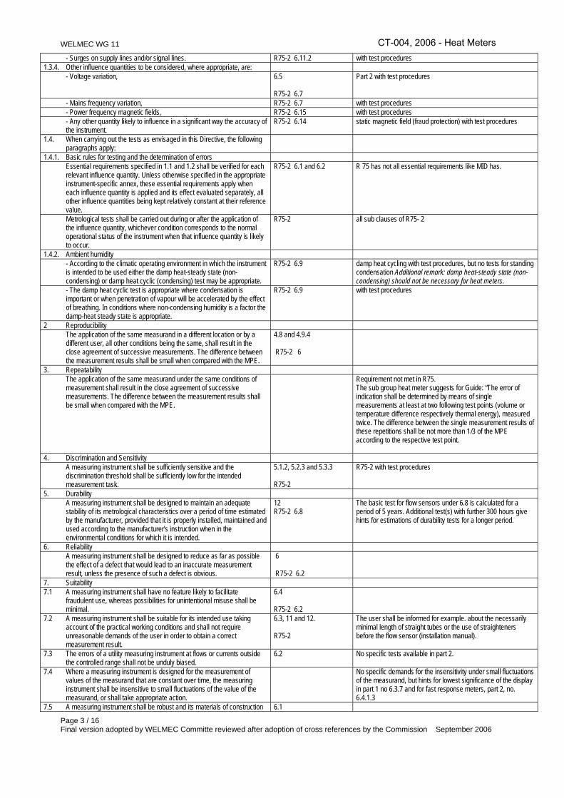
- Surges on supply lines and/or signal lines. R75-2 6.11.2 with test procedures 1.3.4. Other influence quantities to be considered, where appropriate, are: - Voltage variation, 6.5
R75-2 6.7
Part 2 with test procedures
- Mains frequency variation, R75-2 6.7 with test procedures - Power frequency magnetic fields, R75-2 6.15 with test procedures - Any other quantity likely to influence in a significant way the accuracy of
the instrument. R75-2 6.14 static magnetic field (fraud protection) with test procedures
1.4. When carrying out the tests as envisaged in this Directive, the following paragraphs apply:
1.4.1. Basic rules for testing and the determination of errors Essential requirements specified in 1.1 and 1.2 shall be verified for each
relevant influence quantity. Unless otherwise specified in the appropriate instrument-specific annex, these essential requirements apply when each influence quantity is applied and its effect evaluated separately, all other influence quantities being kept relatively constant at their reference value.
R75-2 6.1 and 6.2 R 75 has not all essential requirements like MID has.
Metrological tests shall be carried out during or after the application of the influence quantity, whichever condition corresponds to the normal operational status of the instrument when that influence quantity is likely to occur.
R75-2 all sub clauses of R75- 2
1.4.2. Ambient humidity - According to the climatic operating environment in which the instrument
is intended to be used either the damp heat-steady state (non-condensing) or damp heat cyclic (condensing) test may be appropriate.
R75-2 6.9 damp heat cycling with test procedures, but no tests for standing condensation Additional remark: damp heat-steady state (non-condensing) should not be necessary for heat meters.
- The damp heat cyclic test is appropriate where condensation is important or when penetration of vapour will be accelerated by the effect of breathing. In conditions where non-condensing humidity is a factor the damp-heat steady state is appropriate.
R75-2 6.9 with test procedures
2 Reproducibility The application of the same measurand in a different location or by a
different user, all other conditions being the same, shall result in the close agreement of successive measurements. The difference between the measurement results shall be small when compared with the MPE.
4.8 and 4.9.4 R75-2 6
3. Repeatability The application of the same measurand under the same conditions of
measurement shall result in the close agreement of successive measurements. The difference between the measurement results shall be small when compared with the MPE.
Requirement not met in R75. The sub group heat meter suggests for Guide: “The error of indication shall be determined by means of single measurements at least at two following test points (volume or temperature difference respectively thermal energy), measured twice. The difference between the single measurement results of these repetitions shall be not more than 1/3 of the MPE according to the respective test point.
4. Discrimination and Sensitivity A measuring instrument shall be sufficiently sensitive and the
discrimination threshold shall be sufficiently low for the intended measurement task.
5.1.2, 5.2.3 and 5.3.3 R75-2
R75-2 with test procedures
5. Durability A measuring instrument shall be designed to maintain an adequate
stability of its metrological characteristics over a period of time estimated by the manufacturer, provided that it is properly installed, maintained and used according to the manufacturer's instruction when in the environmental conditions for which it is intended.
12 R75-2 6.8
The basic test for flow sensors under 6.8 is calculated for a period of 5 years. Additional test(s) with further 300 hours give hints for estimations of durability tests for a longer period.
6. Reliability A measuring instrument shall be designed to reduce as far as possible
the effect of a defect that would lead to an inaccurate measurement result, unless the presence of such a defect is obvious.
6 R75-2 6.2
7. Suitability 7.1 A measuring instrument shall have no feature likely to facilitate
fraudulent use, whereas possibilities for unintentional misuse shall be minimal.
6.4 R75-2 6.2
7.2 A measuring instrument shall be suitable for its intended use taking account of the practical working conditions and shall not require unreasonable demands of the user in order to obtain a correct measurement result.
6.3, 11 and 12. R75-2
The user shall be informed for example. about the necessarily minimal length of straight tubes or the use of straighteners before the flow sensor (installation manual).
7.3 The errors of a utility measuring instrument at flows or currents outside the controlled range shall not be unduly biased.
6.2
No specific tests available in part 2.
7.4 Where a measuring instrument is designed for the measurement of values of the measurand that are constant over time, the measuring instrument shall be insensitive to small fluctuations of the value of the measurand, or shall take appropriate action.
No specific demands for the insensitivity under small fluctuations of the measurand, but hints for lowest significance of the display in part 1 no 6.3.7 and for fast response meters, part 2, no. 6.4.1.3
7.5 A measuring instrument shall be robust and its materials of construction 6.1
CT-004, 2006 - Heat Meters

WELMEC WG 11
Page 4 / 16 Final version adopted by WELMEC Committe reviewed after adoption of cross references by the Commission September 2006
shall be suitable for the conditions in which it is intended to be used. 7.6 A measuring instrument shall be designed so as to allow the control of
the measuring tasks after the instrument has been placed on the market and put into use.
6.3.7 for indication service, and for instance an error displayed, it is possible to control the measuring tasks of the heat meters after it has been installed but it is necessary to remove the meter from the pipe.
If necessary, special equipment or software for this control shall be part of the instrument. The test procedure shall be described in the operation manual.
R75-2 8.1 Software flow chart and description
When a measuring instrument has associated software which provides other functions besides the measuring function, the software that is critical for the metrological characteristics shall be identifiable and shall not be inadmissibly influenced by the associated software.
R75-2 8.1 No special requirement for this, only to provide documentation. Suggestion to use WELMEC 7.2, but is not mandatory
8. Protection against corruption 8.1 The metrological characteristics of a measuring instrument shall not be
influenced in any inadmissible way by the connection to it of another device, by any feature of the connected device itself or by any remote device that communicates with the measuring instrument.
R75-2 6.11, 6.12 and 6.13 interconnection interfaces, EMC tests at connector points and part 2, no. 8.1 (software flow chart and description) There is no requirement for testing the influence of ancillary devices.
8.2 A hardware component that is critical for metrological characteristics shall be designed so that it can be secured. Security measures foreseen shall provide for evidence of an intervention.
information to be delivered with the meters or sub-assemblies. No special requirements are given in R75.
8.3 Software that is critical for metrological characteristics shall be identified as such and shall be secured.
No special requirements are given. See WELMEC 7.2
Software identification shall be easily provided by the measuring instrument.
No special requirements are given. See WELMEC 7.2
Evidence of an intervention shall be available for a reasonable period of time.
No special requirements are given. See WELMEC 7.2
8.4 Measurement data, software that is critical for measurement characteristics and metrologically important parameters stored or transmitted shall be adequately protected against accidental or intentional corruption.
6.3.2 and 6.5.1 to 6.5.4 Requirements for the measurement values to be stored for 1 year (§ part 1 6.3.2) but no requirement to protect the data, parameters, software in order to measure properly after intentional corruption (attempt).
8.5. For utility measuring instruments the display of the total quantity supplied or the displays from which the total quantity supplied can be derived, whole or partial reference to which is the basis for payment, shall not be able to be reset during use.
6.3.7 There are no general requirements to avoid resetting of the meter except for the case of overflow.
9 Information to be borne by and to accompany the instrument 9.1 A measuring instrument shall bear the following inscriptions: - manufacturer's mark or name; 11 - information in respect of its accuracy, 11 plus, when applicable: - information in respect of the conditions of use; 11 - measuring capacity; 11 and 6.3.7 - measuring range; 7 - identity marking; 11 - number of the EC-type examination certificate or the EC design
examination certificate; part 1, no.6.4 (identity mark)
- information whether or not additional devices providing metrological results comply with the provisions of this Directive on legal metrological control.
9.2 An instrument of dimensions too small or of too sensitive a composition to allow it to bear the relevant information shall have its packaging, if any, and the accompanying documents required by the provisions of this Directive suitably marked.
Not applicable
9.3 The instrument shall be accompanied by information on its operation, unless the simplicity of the measuring instrument makes this unnecessary. Information shall be easily understandable and shall include where relevant:
- rated operating conditions; 11 The operation instructions have to be specified in all details. - mechanical and electromagnetic environment classes; 11 and 12a only for environmental classes described; under no. 12a,
damage by shock and vibration - the upper and lower temperature limit, whether condensation is
possible or not, open or closed location; 11 not for standing condensing
- instructions for installation, maintenance, repairs, permissible adjustments;
12 without maintenance and repairs
- instructions for correct operation and any special conditions of use; 12 - conditions for compatibility with interfaces, sub-assemblies or
measuring instruments. 11
9.4 Groups of identical measuring instruments used in the same location or 12
CT-004, 2006 - Heat Meters
WELMEC WG 11
Page 5 / 16 Final version adopted by WELMEC Committe reviewed after adoption of cross references by the Commission September 2006
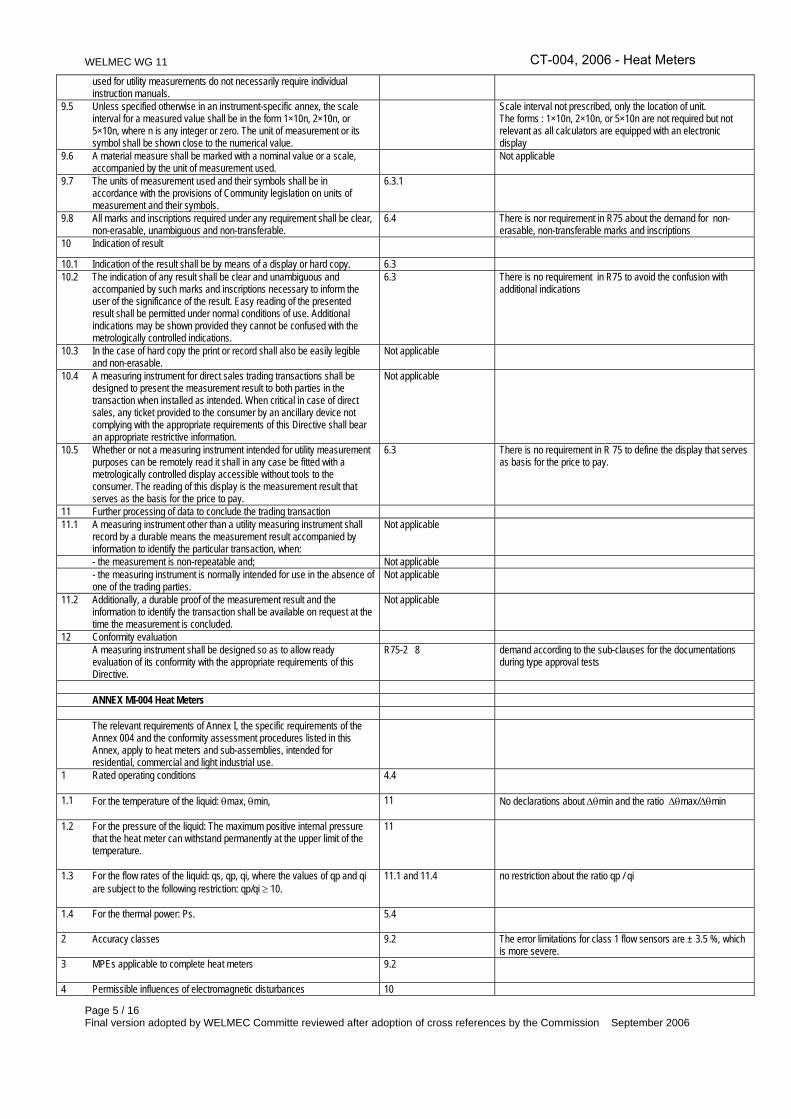
used for utility measurements do not necessarily require individual instruction manuals.
9.5 Unless specified otherwise in an instrument-specific annex, the scale interval for a measured value shall be in the form 1×10n, 2×10n, or 5×10n, where n is any integer or zero. The unit of measurement or its symbol shall be shown close to the numerical value.
Scale interval not prescribed, only the location of unit. The forms : 1×10n, 2×10n, or 5×10n are not required but not relevant as all calculators are equipped with an electronic display
9.6 A material measure shall be marked with a nominal value or a scale, accompanied by the unit of measurement used.
Not applicable
9.7 The units of measurement used and their symbols shall be in accordance with the provisions of Community legislation on units of measurement and their symbols.
6.3.1
9.8 All marks and inscriptions required under any requirement shall be clear, non-erasable, unambiguous and non-transferable.
6.4 There is nor requirement in R75 about the demand for non-erasable, non-transferable marks and inscriptions
10 Indication of result
10.1 Indication of the result shall be by means of a display or hard copy. 6.3 10.2 The indication of any result shall be clear and unambiguous and
accompanied by such marks and inscriptions necessary to inform the user of the significance of the result. Easy reading of the presented result shall be permitted under normal conditions of use. Additional indications may be shown provided they cannot be confused with the metrologically controlled indications.
6.3 There is no requirement in R75 to avoid the confusion with additional indications
10.3 In the case of hard copy the print or record shall also be easily legible and non-erasable.
Not applicable
10.4 A measuring instrument for direct sales trading transactions shall be designed to present the measurement result to both parties in the transaction when installed as intended. When critical in case of direct sales, any ticket provided to the consumer by an ancillary device not complying with the appropriate requirements of this Directive shall bear an appropriate restrictive information.
Not applicable
10.5 Whether or not a measuring instrument intended for utility measurement purposes can be remotely read it shall in any case be fitted with a metrologically controlled display accessible without tools to the consumer. The reading of this display is the measurement result that serves as the basis for the price to pay.
6.3 There is no requirement in R 75 to define the display that serves as basis for the price to pay.
11 Further processing of data to conclude the trading transaction 11.1 A measuring instrument other than a utility measuring instrument shall
record by a durable means the measurement result accompanied by information to identify the particular transaction, when:
Not applicable
- the measurement is non-repeatable and; Not applicable - the measuring instrument is normally intended for use in the absence of
one of the trading parties. Not applicable
11.2 Additionally, a durable proof of the measurement result and the information to identify the transaction shall be available on request at the time the measurement is concluded.
Not applicable
12 Conformity evaluation A measuring instrument shall be designed so as to allow ready
evaluation of its conformity with the appropriate requirements of this Directive.
R75-2 8 demand according to the sub-clauses for the documentations during type approval tests
ANNEX MI-004 Heat Meters The relevant requirements of Annex I, the specific requirements of the
Annex 004 and the conformity assessment procedures listed in this Annex, apply to heat meters and sub-assemblies, intended for residential, commercial and light industrial use.
1 Rated operating conditions
4.4
1.1 For the temperature of the liquid: θmax, θmin,
11 No declarations about ∆θmin and the ratio ∆θmax/∆θmin
1.2 For the pressure of the liquid: The maximum positive internal pressure that the heat meter can withstand permanently at the upper limit of the temperature.
11
1.3 For the flow rates of the liquid: qs, qp, qi, where the values of qp and qi are subject to the following restriction: qp/qi ≥ 10.
11.1 and 11.4 no restriction about the ratio qp / qi
1.4 For the thermal power: Ps.
5.4
2 Accuracy classes
9.2 The error limitations for class 1 flow sensors are ± 3.5 %, which is more severe.
3 MPEs applicable to complete heat meters
9.2
4 Permissible influences of electromagnetic disturbances 10
CT-004, 2006 - Heat Meters

WELMEC WG 11
Page 6 / 16 Final version adopted by WELMEC Committe reviewed after adoption of cross references by the Commission September 2006
R75-2 6 4.1 The instrument shall not be influenced by static magnetic fields and by
electromagnetic fields at mains frequency.
R75-2 6.14 and 6.15
4.2 The influence of an electromagnetic disturbance shall be such that the change in the measurement result is not greater than the critical change value as laid down in requirement 4.3 or the indication of the measurement result is such that it cannot be interpreted as a valid result.
R75-2 4 The critical change value is not used as wording in R 75, there is the significant fault which is equivalent , see part 1, no. 4.10.3. Significant fault.
4.3 The critical change value for a complete heat meter is equal to the absolute value of the MPE applicable to that heat meter (see paragraph 3).
4.10.3 The critical change value is not used as wording in R 75, but the MPE’s are the same before, during and after the disturbances.
5 Durability
Not covered by R75
5.1 Flow sensors: The variation of the measurement result after the durability test, when compared with the initial measurement result, shall not exceed the critical change value.
4.9.4 The critical change value is not used as wording in R 75, but in Part 1 is a definition for the durability error. Under Part 2, no. 6.8 is described that the meters shall meet the MPE (significant fault).
5.2 Temperature sensors: The variation of the measurement result after the durability test, when compared with the initial measurement result, shall not exceed 0.1 °C.
R75-2 6.8.2
6 Inscriptions on a heat meter
11
7 Sub-assemblies
11.1; 11.2 and 11.3
7.1 The relative MPE of the flow sensor, expressed in %, for accuracy classes:
9.2
Class 1: Ef = ± (1 + 0.01 qp / q), not more than ± 3.5 % Class 2 (like in MI-004): Ef = ± (2 + 0.02 qp / q), not more than ± 5 % Class 3 (like in MI-004): Ef = ± (3 + 0.05 qp / q), not more than ± 5 % The limitation for class 1 is smaller than in MI-004.
7.2 The relative MPE of the temperature sensor pair, expressed in %:
9.2.2.2 Et = ± (0.5 + 3 ∆θmin / ∆θ)like in MI-004
7.3 The relative MPE of the calculator, expressed in %:
9.2.2.1 Ec = ± (0.5 + ∆θmin / ∆θ)like in MI-004
7.4 The critical change value for a sub-assembly of a heat meter is equal applicable to the sub-assembly (see paragraphs 7.1, 7.2 or 7.3).
9.2, 4.10.3 Critical change value is not described as wording in R 75.
7.5 Inscriptions on the sub-assemblies
11
8 PUTTING INTO USE
Not covered by OIML
(a) Where a Member State imposes measurement by means it shall allow such measurement to be performed by mean of any Class 3 meter.
Not covered by OIML
(b) Where a Member State imposes measurement of commercial and/or light industrial use, it is authorised to require any Class 2 meter.
Not covered by OIML
(c) As regards the requirements under paragraphs 1.1 to 1.4, Member States shall ensure that determined by the distributor or the person legally designated for installing the meter, so appropriate for the accurate measurement of consumption that is foreseen or foreseeable.
Not covered by OIML
CT-004, 2006 - Heat Meters


