Welsh Government Procedure & Advice Guidance (PAG) 112/20 Stone Mastic Asphalt Specification Instructions for Use This is a new surface course specification, which describes a range of Stone Mastic Asphalt (SMA) mixtures based on German and Scottish specifications and practices. These mixtures consist of a gap-graded aggregate mix, modified bitumen and stabilised with natural fibres. New SMA surface courses shall be treated with grit to increase early life skidding resistance. Document Control Version Date Status Written Checked Approved 2 Aug 20 Final PJ DT NB JJF NB RM
Transcript
Welsh Government Procedure & Advice Guidance (PAG) 112/20
Stone Mastic Asphalt Specification
Instructions for Use This is a new surface course specification, which describes a range of Stone Mastic Asphalt (SMA) mixtures based on German and Scottish specifications and practices. These mixtures consist of a gap-graded aggregate mix, modified bitumen and stabilised with natural fibres. New SMA surface courses shall be treated with grit to increase early life skidding resistance.
Document Control
Version Date Status Written Checked Approved
2 Aug 20 Final PJ DT NB
JJF NB
RM
PAG 112/20 Page | 2
Table of Contents
1. Background Note
2. General Requirements and Definitions
3. Preparatory Work
4. WG Stone Mastic Asphalt
5. Type Approved Installation Trial (TAIT) Process
6. Skidding Resistance
7. Installation Plan
8. Sampling and Testing
9. Tables and Figures
10. Approval Certificate
PAG 112/20 Page | 3
1. Background Note
Hot Rolled Asphalt (HRA) surface course with pre-coated chippings was the material of choice on the UK motorway and trunk road network, until the mid-1990s. Asphalt technology developments in mainland Europe resulted in a range of proprietary surfacing materials known as Thin Surface Course Systems (TSCSs) being incorporated into the Specification for Highway Works (SHW). This change was driven by the need for improved surface course performance, especially for greater resistance to deformation, faster speed of installation, a significant reduction in road traffic noise and significantly less working space requirements. As a result, TSCSs were adopted for use throughout Wales, as it was expected they would be as durable as HRA but without its disadvantages. They soon became the default surface course materials since their use required no formal departure from standards. However by the mid-to late 2000’s Trunk Road Agents (TRAs) operational personnel were increasingly concerned about the relatively poor in service performances of some TSCSs, which had perhaps been exacerbated by occasional more severe winters. In 2012, this concern became widespread as the Welsh motorway and trunk road network deteriorated. Welsh Government (WG) then commissioned the Transport Research Laboratory (TRL), Halcrow and Transport Scotland (TS) to investigate the poor performance of the TSCSs. Specifically their work was to establish the causes of such poor performance, identify areas where improvements could be made and to recommend enhancements to the current specifications. Their work was published as “Client Project Report 1392: Performance of Thin Surfacing in Wales - June 2012” and the main conclusion was that Welsh TSCSs had an average service life of no more than 7 years. The report identified both short and long-term recommendations including:
The introduction of minimum binder contents for TSCSs
The selection of more suitable materials for specific locations
A review of the framework contractors’ quality management systems
The need for Improvements in site supervision
The need for increased collaboration with industry. Based on these recommendations the WG TSCSs Forum was formed in 2014. Representatives included material suppliers, specialist consultants, TRAs and WG. As a result:
Site supervision was increased (unsuccessfully)
A supervision checklist was created
Highways England surfacing Interim Advice Notes (IANs) were amended for WG requirements and adopted by WG
PAG 112/20 Page | 4
WG representatives and a consultant materials engineer drafted a Welsh TSCSs specification.
These actions had very limited success since their introduction. Consequently, in 2015 after reorganisation WG engineers began to develop the recommended longer-term strategy:
“The development of a new national surface course specification, such as the one recently introduced in Scotland (TS Interim Amendment No 35, 2010) should be considered. The Scottish specification has been developed to produce denser binder rich mixes using smaller stone sizes”.
WG Stone Mastic Asphalt (SMA) specification is based on our German and Scottish cousin’s experience, edited to capture the experiences gathered by the WG working group. TS representatives have been very generous in sharing their knowledge. The TS2010 specification has provided the foundation of this document.
PAG 112/20 Page | 5
2. General Requirements and Definitions 2.1 General
This is a new surface specification, which describes a range of SMA mixtures based on German and Scottish specifications and practices. These mixtures consist of a gap-graded aggregate mix, modified bitumen and stabilised with natural fibres. New SMA surface courses shall be treated with grit to increase early life skidding resistance. WG have worked with TS operatives, to attain the necessary knowledge base and assess the performance of this true resemblance of SMA. WG approved the progression of this specification based on SMA’s proven record in Germany and current Scottish experience. WG expects its adoption will result in the following benefits:
Increased durability
Decreased routine maintenance interventions
Increased use of sustainable local aggregate
Reduced use of premium aggregate
Good skidding resistance
Excellent ride quality
Improvements in quality management systems
Lower whole life costs.
2.2 Construction Products Regulations For general details regarding the Construction Products Regulations, refer to Interim Advice Note 177/14(W). With regard to bituminous materials, Welsh Government has prepared this specification to comply with the CPR in respect of road construction products for the use on the Motorway and Trunk Road Network in Wales. 2.3 Harmonised Technical Specifications The SMA mixtures within this specification conform to BS EN 13108- 5 – Stone Mastic Asphalt.
2.4 Quality Control and Assurance Conformity shall be established in accordance with BS EN 13108-20 - Type Testing and BS EN 13108-21 – Factory Production Control.
PAG 112/20 Page | 6
2.5 Relationship to Overseeing Organisation National Manuals The Design Manual for Roads and Bridges (DMRB) volume 7, section 5, part 3 CD236 WG National Application Annex - Surface Course Materials for Construction, Table W1/1 sets the parameters for permitted surface course materials for use on the Welsh Motorway and Trunk Road Network. All future amendments to Table W1/1 shall be made through the WG National Application Annex. Specification for Highways Works (SHW) Clauses 901 and 903 apply to this specification. Reference documents both normative and informative, such as European, British Standards along with Overseeing Organisation publications etc., when referenced relate to the most recent published version unless otherwise stated. Where there is conflict between this specification and others, including the referenced specifications, the requirements set out in this document take precedence.
2.6 Definitions and Abbreviations
Bond Coat Polymer modified bitumen emulsion to promote the adhesion between layers within a pavement construction. Or a bond between a new surface course to an existing pavement layer. (The use of a bond coat rather than the traditional tack coat, is to be considered as best practice.)
Course Structural element of a pavement constructed with a single material. A course may be laid or consist of one or more layers.
Contractor Installer of the works.
CPR Construction Products Regulation.
Client Commissioning body that directly or indirectly funds projects. The client can also be referred to as:
Employer
Promoter
Owner
Purchaser
Principal
User
Developer
Authority.
HRA Hot Rolled Asphalt, is a dense gap graded bituminous mixture in which the mortar of fine aggregate, filler and binder contributes to the performance of the laid material.
PAG 112/20 Page | 7
HRA conforms to the requirements of BS EN 13108-4. Further advice and guidance can be found in PD 6691 - Guidance on the use of BS EN 13108, Bituminous Mixtures – Material Specification.
Layer Element of a pavement laid in a single operation.
Minimum Thickness The thickness of the layer at any point to allow for tolerances during installation. Under no circumstances shall it be taken as a thickness to which the layer can be reduced for installation.
Minimum Binder Content
The lowest binder content at which a mixture shall be produced.
Nominal Thickness The layer thickness specified by the Client/Clients representatives in Appendix 7/1 and used to measure for compliance purposes.
Pavement Multiple courses of materials, which form a structure providing a safe passage for road traffic.
Regulating course A course of variable thickness applied to a pavement course to adjust the profile, prior to being overlaid.
SMA A gap graded asphalt mixture with a high polymer modified bitumen content, low void content and stabilised with natural fibres.
Surface Course The top course of the pavement, with which traffic is in contact.
Tack coat Conventional bitumen emulsion used to promote adhesion between courses but confined to footway use
PAG 112/20 Page | 8
3. Preparatory Works
3.1 Cold milling of bituminous bound flexible pavements Cold milling shall be carried out to the requirements of Clause 709 using methods, which minimise excessive fumes, smoke and dust. Dust shall be minimised by dampening with water from spray bars fitted to cold milling machines. 3.1.2 The transverse profile of the milled surface shall be uniform for the width of the overlaying course, except when profile milling before laying an overlay. Any variation greater than 10mm measured transversely using a 3-metre straight edge, placed at right angles to the direction of planing, shall be remedied before further preparatory work commences. 3.1.3 Carriageways shall be milled to the tolerances in Clause 702. If tolerances are exceeded, the full extent of the non-compliant area shall be rectified by further milling or by regulating using materials complying with Clause 907 and Clause 3.2 of this specification. 3.1.4 The edges shall be cut vertical in straight lines. Where the edge forms a permanent joint at surface course level, it shall be sawn to the full depth of the layer. The contractor shall brush and sweep the cut edges and the surface by mechanical means to produce a uniform and clean surface. 3.1.5 Existing ironwork shall not be disturbed by the milling action. Where necessary, surfacing in the vicinity of the ironwork and in other small or irregular areas shall be removed with the use pneumatic tools or other suitable methods. 3.1.6 Where milling is carried out on a carriageway open to traffic, temporary ramping and traffic management measures shall be provided to ensure the safe passage of vehicles. 3.1.7 Where milling is required over extensive areas, the Contractor shall programme the work to allow removal of full lane widths as far as practicable. The Contractor shall include his proposals for milling to the employers/clients representative within the works proposals. 3.1.8 Immediately after milling, surplus material including all dust and loose debris shall be removed and the milled surface swept provide a clean and regular temporary running surface. 3.2 Regulating Course A course consisting of one or more layers of bituminous material laid to provide for surface regularity and constant nominal thickness of the overlay. When laid over an irregular substrate the regulating course will be of varying thickness. Regulating courses shall be installed with a bond coat.
PAG 112/20 Page | 9
Note 1: Throughout WG’s SMA Trials, HRA complying with Clause 911(W), specifically HRA 55/10C des surf 40/60 (High Stone Content Asphalt) has proven to be both a reliable binder and regulating course material. See PD6691 and Clause 911(W) re mix design.
PAG 112/20 Page | 10
4. WG Stone Mastic Asphalt Surface Course - Specification
4.1 General The SMA mixtures within this specification conform to BS EN 13108-5 wherever applicable. Conformity shall be established in accordance with BS EN 13108-20 - Type Testing and BS EN 13108-21 – Factory Production Control. All clauses within this specification shall have no prefix (e.g. 2.2.1). Other standards and specifications are referenced by the associated source documentation. Reference documents both normative and informative, such as European and British Standards along with Overseeing Organisation publications etc., when referenced relate to the most recent published version unless otherwise stated.
The Specification for Highways Works (SHW) Clauses 901 and 903 apply to this specification. Further guidance in Road Note 42 and SHW Clause 903, placing and compacting joints provide additional information in achieving durable asphalt. WG SMA is to be principally machine laid whenever possible. 4.1.2 Validity Validity of the product shall comply with BS EN 13108-20 Type Testing Clause 4.2, Sub-clause 4.2.1, 4.2.2 and 4.25. 4.2 Constituent Materials 4.2.1 Binder The binder shall be 75/130-75 polymer modified binder conforming to BS EN 14023. Compliance and test data for the binder proposed shall be included as part of the Type Approval Installation Trial (TAIT) requirements (see Tables 1, 2.1, & 3). Note 1: PMB 75/130-75 has been specified for WG SMA. This PMB covers a large envelope of service temperatures and elastic properties to improve the toughness of the material. This PMB has a penetration range of 75 to 130 (Class 7) and a minimum softening point of 75oC (Class 3). However, confirmation of all the properties listed in Tables 2 and 3 will be required. 4.2.1.1 Additional PMB Information The predominant type of bitumen modification is the addition of synthetic rubber, the preference being Styrene-Butadiene-Styrene (SBS).
PAG 112/20 Page | 11
4.2.2 Aggregate 4.2.2.1 Coarse aggregate The coarse aggregate used in SMA shall be material substantially retained on a 2,0mm test sieve, conforming to all appropriate requirements of BS EN 13043 and consisting of crushed rock of one or more of the following groups:
Basalt
Gabbro
Granite
Gritstone
Hornfels
Porphyry
Quartzite. Note 1: Aggregate outside of these rock groups that can demonstrate a history of successful use as a surfacing aggregate may also be proposed. 4.2.2.1.1 Particle Density The particle density shall be determined in accordance with BS EN 1097-6, Clause 8 or 9, depending upon the size of the aggregate, and the results declared (see Table 1). 4.2.2.1.2 Particle Shape The flakiness index for the course aggregate shall be FI20. Note 1: Coarse aggregate particle shape is important as it influences the arrangement and strength of the aggregate matrix and resultant surface texture. It is therefore important that the flakiness index is <20. A flakiness index of <15 is regarded as ideal. 4.2.2.1.3 Fines content The fines content category for the coarse aggregate shall be f4. 4.2.2.1.4 Resistance to polishing The polished stone value category for the coarse aggregate shall be declared (see Table 1). All aggregate used for WG SMA shall be tested for performance, please see Chapter 6 for requirements. Note 1: The introduction of the performance requirement for skid resistance within WG SMA and the adoption of a PSVDeclared value in the contract, provides the opportunity to adopt and verify the satisfactory performance of aggregates with variant PSVs. Consequently values of PSV shall be stated. Note 2: Economic and environmental factors enable suitable locally sourced aggregate to be used for surfacing materials on the WG Motorways and Trunk Road Network. This overrides the prescriptive PSV requirements of the DMRB.
PAG 112/20 Page | 12
Note 3: The advantages of using locally sourced aggregates are that it reduces the need to haul high PSV stone over long distances and reduces cost. The safety related aspects of using lower PSV aggregates are addressed by ensuring the in-service grip performance of the completed surfacing works meet the WG friction criteria. 4.2.2.1.5 Resistance to fragmentation The resistance to fragmentation for coarse aggregate shall be LA30.
4.2.2.1.6 Resistance to surface abrasion The resistance to surface abrasion for the coarse aggregate shall be AAV12 (see Table 1).
4.2.2.1.7 Resistance to wear The resistance to wear for the coarse aggregate shall be MDE declared.
4.2.2.2 Fine aggregate The fines content category for fine aggregate shall be f22
Note 1: The fine aggregate used in the SMA shall substantially pass a 2,0mm test sieve and be a crushed material from one or more of the groups specified in 4.2.2.1. 4.2.3 Added Filler Type of added filler All added filler used in the SMA shall be limestone and shall comply with the grading of BS EN 13043, clause 4.3.6. Notwithstanding this, hydrated lime may be added up to a maximum of 2% by mass of the aggregate. 4.2.3.1 Bulk density The loose bulk density in kerosene of added filler, with the exception of the hydrated lime, shall be in accordance with BS EN 13043, Clause 5.5.5. 4.2.4 Recycled material The use of a recycled aggregate or reclaimed asphalt is not permitted. 4.2.5 Additives Fibres shall be added at the mixing plant. Wherever possible, these shall be in pelleted form, either wax-coated or bitumen coated. The SMA mixtures shall include a minimum fibre content of 0.3% by mass 4.2.5.1 Other permitted additives include special fillers, adhesion and workability agents subject to the suitability of any additives being demonstrated in accordance with BS EN 13108-5, Clause 4.2.2. A stabilising additive shall be used to achieve the high binder content
PAG 112/20 Page | 13
in WG SMA mixtures. Current practice of producing SMA’s without a stabilising additive shall be discontinued. Note 1: The addition of a PMB used in this specification requires the stabilising additive to act as a carrier for the binder, thus ensuring the binder does not drain off the aggregate during the production, storage and transportation stages (see Table 3). 4.2.5.2 The Type Approved Installation Trial (TAIT) process should provide evidence that technical studies have demonstrated the following:
Fibres are not pulverised or destroyed during dry mixing
Fibres do not clump together
Good fibre distribution can be achieved with different types of mixing plant
An hour after production at the maximum mixing temperature, binder lost by
drainage is limited.
Note 1: Although to a degree subjective, an assessment can be made of the proportion of the fibres recovered following binder extraction by sieving and weighing. Around two thirds of the fibres should be retained on the various sieve sizes. If only one third or less is retained this demonstrates, a problem with fibre distribution. When recovered fibres are dark brown and the ring and ball results are high, then the plant mixing temperature is likely to have been excessive.
PAG 112/20 Page | 14
5. Type Approved Installation Trial (TAIT) Process
5.1 Fundamental Requirements The producer shall undertake the TAIT process set for each variant of the WG SMA material to be produced. Any changes to the constituent materials, mixing plant or surfacing contractor is considered to be a variant. 5.1.2 General Requirements 5.1.2.1 TAIT Process The TAIT is a three-stage process, as shown within Figure 3. Where the required properties, test methods and limits are detailed in Tables 2.1, 2.2 & 2. 3. Each stage of the TAIT process shall be approved by WG before progressing to the next stage. 5.1.2.2 Stages Stage 1 is a laboratory validation trial. Stage 2 is a product mix trial, which comprises a minimum 20 tonne batch produced at the proposed mixing plant. The batch shall be sufficient to lay a minimum length of 60m. Stage 3 is a network level trial, which shall be a minimum length of 300m. 5.2 TAIT Stage 1 – Laboratory Validation 5.2.1 Composition Note 1: Categorising the binder content in BS EN 13108-5 involves a correction for the density of the aggregate in the mixture. The principle is that the binder content category in the standard is based on the aggregate density in the mixture of 2.650 Mg/m3. If the aggregate is denser than 2.650 Mg/m3, the actual binder content in the true mixture is reduced proportionally, or if the aggregate is less dense, it is increased. This adjustment has the intention of giving the same binder volume in the mixtures regardless of aggregate density. Note 2: A consideration of UK mixtures and aggregates indicated that this approach might have been detrimental to performance because, in practice, some of the denser aggregates need higher binder contents for durability. For this reason, the binder contents set out in Table 1 are those which are required as actual binder contents on analysis of the finished mixture with no density correction. These binder contents are referenced as Bact.
Note 3: Bact will need to be corrected back to determine the Bmin defined in BS EN 13108-5 using the following formula:
Bmin X Bact
PAG 112/20 Page | 15
Note 4: Where Pb is the mean particle density of the aggregate mixture, in megagrams per cubic metre (Mg/m3), determined in accordance with BS EN 1097-6.
5.2.2 Grading and binder content The grading of the composition of the SMA shall conform to the relevant column of Table 1. Grading envelopes are given in Fig 1 to Fig 2. The supplier is required to choose targets that comply with the grading limits given in Table 1. 5.2.2.1 Tolerances specified in BS EN 13108-21 shall be applied to the target grading. 5.2.2.2 The tolerance applying to the minimum target binder content (Bact) in Table 1 shall be ±0:2% by mass. This compliance criterion shall be applied to a rolling mean of the analyses of four samples to determine binder content in accordance with BS EN 12697-1. Note 1: The high content of the coarsest aggregate is required to form a mixture that is gap-graded. Such grading in essential to create the desired coarse aggregate skeleton that will accommodate the mastic: i.e. binder, fine aggregate and filler. Binder content tolerance Note 1: The use of a tight tolerance +0.2% (by mass) on the binder content emphasises the importance of closely controlling the amount of binder in the mix. In addition, the target values given are higher than those used in current UK mixtures. Evidence from Germany and Scotland highlights that high binder contents, with a close degree of control, are a fundamental requirement in ensuring the durability of an SMA. 5.2.3 Air void content The air voids content of laboratory compacted specimens of the mixtures at target composition prepared and tested as detailed in BS EN 13108-20, Annex C, Table C.1, shall be as follows: 5.2.3.1 The average void content category for SMA 10 surf of a set of three specimens of shall be Vmin3; Vmax4. See Table 2.1. 5.2.3.2 The average void content category for SMA 6 surf of a set of three specimens shall be Vmin3.5; Vmax4.5. See Table 2.1. Note 1: The limits on the laboratory-prepared specimens are set at a tolerance such that the limits on the laid and compacted mat should subsequently be more readily achievable.
PAG 112/20 Page | 16
5.2.4 Binder Drainage The average binder drainage category of a set of specimens tested in accordance with BS EN 12697-18, Clause 5 (Beaker Method), shall be D0.3, see Table 2.1. Note 1: The Beaker method describes a procedure for determining the binder drainage of asphalt mixtures incorporating fibres and enables the effects of any ant-draining additive to be quantified. The WG SMA specification requires the difference between the mixture mass before and after heating to be ≤0.3%. 5.2.5 Water Sensitivity The water sensitivity shall be tested in accordance with BS EN 12697-12, category shall be ITSR80, see Table 2.1. 5.2.6 Binder Penetration The binder penetration shall be tested in accordance with BS EN 1426, category shall be Pen 75-130 (Class 7), see Table 2.1 and Table 3. 5.2.7 Softening Point The softening point shall be tested in accordance with BS EN 1427, category shall be 75⁰C min (Class 3), see Table 2.1 and Table 3. 5.2.8 Resistance to Permanent Deformation Samples for determining the resistance to permanent deformation shall be laboratory mixed in accordance with BS EN 12697-35, compacted in accordance with BS EN 12697-33 roller compactor (BS EN 13108-20 Table C.1 ref C.1.25) and tested in accordance with BS EN 12697-22 small device, method B in air at a test temperature of 60°C. 5.2.9 Data recorded An electronic report shall be submitted to WG by the supplier within 14 days. The report shall contain all the necessary information for each stage of the TAIT process. 5.2.10 Information to be supplied for Stage 1 approval Summary of TAIT Stage 1 - laboratory design results:
Coarse aggregate source and geological rock group
PAG 112/20 Page | 17
Fine aggregate source and geological rock group
Filler source and supplier
Bitumen source and supplier
Proposed production plant
Compliant set of Table 2.1 test results. 5.2.11 Material testing All testing shall be undertaken by a UKAS accredited laboratory. CE markings for constituent materials or UKAS test certificates shall be supplied upon completion. 5.3 TAIT Stage 2 – Plant Trial 5.3.1 Binder and Grading Analysis The instructions, guidelines and the procedures for sampling and testing are listed in Chapter 8 Clause 8.1.1. Composition shall comply with the requirements of Table 2.2. 5.3.2 Air void content For the determination of air void content, see Chapter 8 Clause 8.2. The air void content shall comply with the requirements of Table 2.2. 5.3.2.1 Laid and compacted mat The protocol in Chapter 8 accords with BS594987, Annex G relating to the determination of void content and resistance to permanent deformation of SMA binder course and regulating courses. As part of the TAIT Stage 2, this protocol shall be used to determine the in situ void content of the SMA surface course only. The trial strip shall be as per Annex G with a minimum thickness as stated in Clause 5.3.5. 5.3.2.2 Correlation between gauge readings and core densities shall be undertaken at this stage. This allows the laid and compacted mat at TAIT Stage 3 to be non-destructively tested as per BS594987, Annex I. 5.3.3 Optional application of grit to the surface course The specification for the grit and its application is obtained in TAIT Stage 3 Clause 5.4.3 and Clause 5.4.4. 5.3.3.1 Composition For specification purposes, grit shall be considered as a mixture and evaluation of conformity determined with BS EN 13108-20 and BS EN 13108-21. See Table 5.
PAG 112/20 Page | 18
5.3.3.2 Surface Texture Texture depth of both the un-gritted and gritted surface are to be tested in accordance with BS EN 13036-1. Note 1: The application of grit to the laid surfacing is optional at this stage. However, surfacing contractors with little or no experience of gritting, may find it beneficial to carry out gritting trials as part of the plant trial. 5.3.4 Transport, Laying and Compaction For instructions and guidance on the installation of the mixture, see Chapters 3 and 7. 5.3.5 Nominal target and minimum compacted layer thickness The minimum layer thickness for all mixtures at this stage is 50mm 5.3.6 Temperature of the mixture All mixing temperatures shall be documented and declared. For the specified PMB, the maximum temperature of the mixture at any stage is 185°C. For further instructions and guidance on the delivery and compaction temperatures of the mixture see Chapter 7. 5.3.7 Trial length The minimal length shall be 60m as per Figure 4. 5.3.8 Information to be supplied for Stage 2 approval:
Compliant set of Table 2.2 test results
Supporting UKAS test certificates
Quality assurance certificate for the production plant
Highways Sector Scheme 16 certification for the paving contractor. 5.3.8.1 All testing shall be undertaken by a UKAS accredited laboratory. CE markings for constituent materials or UKAS test certificates shall be supplied upon completion. 5.3.9 Relaxation on Stage 2 requirement for alternative plant A WG TAIT approved SMA mixture may be supplied from an alternative plant (or supporting plants), provided the mixture is produced using the same production procedures and its operating compliance is level A or B.
PAG 112/20 Page | 19
5.3.10 Relaxation on Stage 2 requirement for alternative aggregate source A WG TAIT approved SMA mixture may be produced using aggregate from an alternative source, provided the batch trial demonstrates:
The overall grading and binder content of the mixture remains the same
The alternative aggregate properties are as per Chapter 4 and Table 1
The in-situ air voids comply with the requirements set out in Table 2.2. 5.4 TAIT Stage 3 – Trunk Road Network Trial 5.4.1 Asphalt compositional analysis Binder Content and Grading 5.4.1.1 A sample shall be taken every 100 tonnes or every 2 hours, but not less than twice per shift / day in accordance with BS EN 12697-27. 5.4.1.2 The sample shall be analysed to determine binder content and grading in accordance with BS EN 12697-1 and BS EN 12697-2, taking note of relevant guidance for modified binders and reporting any corrections factors used. Composition shall be as Table 2.3. 5.4.2 Laid and compacted mat surface course Air Voids 5.4.2.1 The average in-situ air void content of the laid and compacted material shall be continuously assessed using an indirect density gauge in accordance with BS 594987, Annex I, with readings taken at 20m intervals in alternative wheel-tracks. 5.4.2.2 Each gauge shall be individually calibrated for each mixture to be used. The calibrations shall be continually checked and updated based on correlations between gauge readings and core densities determined from the Stage 2 TAIT product mix trial. 5.4.2.3 The compliance criteria, BS 594987 Clause 9.4.2 shall be applied to a rolling mean of the values from three consecutive locations. Air void content shall be as Table 2.3. 5.4.3 Coated Grit for Application to Surface Course 5.4.3.1 For specification purposes, grit shall be considered as a mixture and its evaluation of conformity determined with BS EN 13108-20 and BS EN 13108-21. 5.4.3.2 The grit shall be as coarse aggregate conforming to Clause 4.2.2.1, and shall be produced from an aggregate having a minimum PSV of 50. 5.4.3.3 The grading of the grit shall be as in the relevant column of Table 5.
PAG 112/20 Page | 20
5.4.3.4 The binder shall be 40/60 grade conforming to BS EN 12591. The binder content for each relevant grade shall be as shown in Table 5. The tolerance on the target binder range shall be +/- 0.3%. 5.4.3.5 The coated grit shall be free flowing and free from agglomerations or clumping. 5.4.3.6 The assessment and verification of constancy of performance shall be carried out in accordance with BS EN 13108-5, Clause 6. 5.4.4 Application of the Grit 5.4.4.1 General The grit shall be applied to the surface course at a uniform rate of spread across its full width by suitably equipped rollers and rolled without vibration. For rates of spread, see Table 6. Grit may be applied to hard shoulders but is not required in areas, which will not be trafficked. 5.4.4.2 Timing of grit application The grit shall be applied as soon as there is enough clearance from the paver and in the initial roller passes whilst the surface course is sufficiently hot for the grit to adhere when rolled, this process ensures maximum grit retention. 5.4.4.3 Sweeping 5.4.4.3.1: Grit applied at excessive rates of spread shall be removed by mechanical sweeping, when the surface has cooled to ambient temperature and before the application of the road markings or opening the road to traffic. Note 1: Brushes may need adjusting to remove only loose grit at the surface and not lowered into the macrotexture. 5.4.5 Texture – See Chapter 6, Clause 4. 5.4.6 Information to be supplied for Stage 3 approval:
Compliant set of Table 2.3 test results. 5.4.6.1 All bituminous analysis, void content and texture depth testing shall be undertaken by a UKAS accredited laboratory. CE markings for constituent materials or UKAS test certificates shall be supplied upon completion.
PAG 112/20 Page | 21
6. Skidding Resistance 6.1 Early life skidding resistance – compliance requirements The skidding resistance of the surface shall be measured using the Grip-Tester MK2 brake wheel fixed-slip device in accordance with BS 7941-2. The surface shall be tested at four weeks and six months after opening to traffic at a test speed of 50 km/hour, recording at 10 metre rolling averages. Note 1: A performance requirement for the skid resistance of the finished road surface using a Grip Tester braked-wheel fixed-slip device is used rather following the usual UK convention of specifying the polished stone value (PSV) of the coarse aggregate in the surface course. This enables suitable local aggregate to be used subject to it satisfying these compliance requirements. 6.2 Survey Procedure Prior to any survey, pre-survey checks shall completed in accordance with the manufacturer’s instructions to ensure the Grip-Tester is correctly calibrated. Both the zero-load and zero-drag figures should be recorded. 6.2.1 The surveys shall be carried out at a speed of 50 km/h with a water film depth of 0.25mm. The average recording lengths shall be 10m. 6.2.2 Each section shall be tested twice in the first instance. If the section average values of the first two tests are not within 0.02GN, a third run shall be carried out and the values of the second and third runs compared. 6.2.3 If these values are not within the 0.02GN limits, then the testing shall be discontinued and the cause investigated by checking the condition of the Grip Tester and also examining the road surface for signs of contamination etc. 6.3 Results The minimum Grip Number (GN) after 4 weeks and 6 months trafficking shall be as shown in Table 7. 6.3.1 Reporting The data shall be supplied in CSV, HMDIF format (to allow import into relevant the Pavement Management System), and Shape file (to allow display on a GIS system such as ArcView). Note 1: The graphical output generated on the laptop during the testing shall be supplied to indicate the test speed and water flow.
PAG 112/20 Page | 22
Note 2: The Grip-Number Investigatory Levels for Grip-tester MK2, are based on TRL Published Project Report 1497:2009 Skidding Resistance Conversion: Skid Coefficient = 0.89 x Grip-Number. 6.4 Texture The surface course shall exhibit a uniform macro-texture, which is to be tested in accordance with BS EN 13036-1. 6.4.1 Texture depth will depend on the nominal aggregate size. Table 8 provides guidance on the expected values. Note 1: These values are based on the recorded measurements from the TAIT Stage 3 trial sections, using granite aggregate. Note 2: Although there are no specification requirements for texture depth, such measurement shall be determined and reported.
PAG 112/20 Page | 23
7. Installation Plan
7.1 General This section deals with for the placement of WG SMA. In the event of any conflict between this specification and other referenced documents, the requirements of this document take precedence. 7.1.1 The material shall be transported and laid as specified in BS 594987 and the specific requirements of this document. Note 1: All production, delivery and paving operations must be co-ordinated. A well-organised job will result in reduced waiting times for the delivery vehicles, reduced material temperature loss and less standing time for the paving plant. Note 2: Continuously feeding the paver is an important pre-requisite to achieve an even texture, full compaction, improved ride quality and reduced road traffic noise. 7.2 Receiving Course Any repairs to the road surface, structures, verges and drainage systems shall be completed prior to the commencement of the paving works. Note 1: The receiving course shall be free of mud, detritus and other deposits. It shall also be free of loose and deleterious materials. If it is an existing surface course which is to be overlaid and is in a poor condition, it is recommended that a regulating/binder course is used (see Chapter 3). 7.3 Bond Coat A polymer modified bond coat shall be used in all locations. The minimum rate of spread shall be as specified in BS 594987 Part 5.5. 7.4 Transport The contractor shall include in his quality plan the measures to be taken to ensure the rate of delivery of the material to the paver will enable it to operate continuously. 7.4.1 Delivery vehicle floors shall be clean. To facilitate the discharge of the asphalt they may be sprayed with a suitable release agent or water 7.4.2 Diesel shall not be used in any circumstances.
PAG 112/20 Page | 24
Note 1: The constant supply of the material is necessary to avoid the paver starting and stopping. This produces a poor ride quality, minimises the number of transverse joints and prevents cooling material being left in the paver while awaiting further deliveries. 7.5 Haulage distances Haulage times to site from the production plant shall be kept to a minimum. Note 1: Long haulage distances make it more difficult to achieve a continuous supply because of potential holdups due to traffic problems. They also exacerbate temperature loss of the material. Note 2: Where production plants are more than 2 ½ hours travelling time from the site or where material is likely to be held in the delivery vehicle for more than 2 ½ hours, the use of a material transfer vehicle (MTV) is recommended (Image 1). These have proved successful in remixing asphalt before it is placed, therefore evenly distributing material of varying temperature and especially in minimising segregation.
Image 1: Shuttle buggies used in paving
7.6 Mixture Temperatures The maximum mixing temperature at any stage shall be 185°C. Delivery temperatures exceeding 175°C shall be investigated to ensure the maximum mixing temperature has not been exceeded.
PAG 112/20 Page | 25
7.6.1 The mix temperature of asphalt in the paver hopper should be evenly distributed and the minimum temperature shall be 150°C. 7.6.2 The minimum rolling temperature shall be 130°C Note 1: Asphalt which is too cool cannot be fully compacted and will be less durable 7.6.3 The material shall be laid within the shortest time possible from mixing. An acceptable realistic time is within 2 hours. 7.6.4 Similar to other asphalt materials, SMA shall not be stored for long periods following mixing. This is to prevent damaging changes to the binder. Note 1: Overheating asphalt to counteract the anticipated temperature loss resulting from of long haulage times very seriously degrades the bitumen in a mix and hence the durability of the asphalt. It can also cause binder drainage. The seriousness of overheating asphalt in production cannot be overstated. 7.6.5 The SMA shall not be laid if more than 4 hours has elapsed since it was discharged from the mixer. 7.6.6 Laying records shall include the mixing and delivery times, temperatures on delivery at start of rolling and where each load was laid. 7.7 Limitations of Placement in Respect of Weather Conditions Acceptable conditions for placement shall generally be in accordance with BS 594987 Clause 6.2. 7.7.1 Installation shall be undertaken with due regard to ambient weather conditions. WG SMA shall not be laid on any surface that is covered in frost, ice, snow or standing water. 7.7.2 The material shall not be laid during heavy rain. 7.7.3 The contractor shall decide if weather conditions are suitable to start or continue working. Note 1: Responsibility for the work is the contractors. 7.7.4 Table 9 lists conditions for placement in respect of layer thickness. Note 1: These conditions are for calm or light wind situations. Stronger winds result in wind-chill of the asphalt surface, causing it to cool much more rapidly than low ambient temperatures.
PAG 112/20 Page | 26
Note 2: The ambient temperature on site is a critical factor in the decision to commence or cease laying due to changing temperature. 7.7.5 Material shall not be kept in delivery vehicles, awaiting weather conditions to improve. 7.8 Compaction The paver shall be operated at an appropriate speed so that an adequate degree of pre-compaction is achieved in the freshly laid asphalt. Note 1: The paver should provide 75% to 80% of the asphalts’ compaction, sometimes even more. Checks on the degree of compaction can be made by using a Pavement Quality Indicator (PQI) a non-nuclear density meter or Nuclear Density Meter (NDM). 7.8.1 Compaction of the laid material shall commence without delay and immediately following it being laid. 7.8.2 Any hand laying of SMA shall be done rapidly and at the same time as the paving work. Note 1: To compensate for the hand-laid material not having been pre-compacted by the paver, the as-laid thickness shall be increased as necessary. 7.9 Rollers Compaction shall be undertaken using vibrating tandem rollers in non-vibrating mode or deadweight rollers with smooth steel wheels. Both types shall have a minimum operating weight of 9 tonnes. Note 1: Rubber tyre rollers are ineffective when used with SMA. 7.9.1 Vibratory compaction shall not be used. 7.9.2 Two rollers shall operate with each paver. 7.9.3: Roller operatives shall be experienced and competent in recognising any adverse movement of the asphalt. Note 1: Rolling and roller patterns are difficult to specify, as there are multiple variables such as material/mix type and the environment. Note 2: A slow and steady rolling speed is optimal in achieving the necessary compaction for a durable pavement with good ride quality. Stoppages and high rolling speeds should be avoided as both will result in variations of material density.
PAG 112/20 Page | 27
Note 3: Roller patterns should also be varied, continuing to compact by straight lines will result in indentations visible across the mat. Indentations are easier to remedy with subsequent passes if they are diagonal to the direction of rolling. 7.10 Application of Grit The surface course shall be gritted on the first roller pass. 7.11 Transfer The transfer of the mixture from the delivery vehicles to the paver is also an important factor in achieving a uniform surface with good ride quality. 7.11.1 A banks-man shall guide the delivery vehicles to a stationary position in front of the paver but shall ensure the vehicle does not bump into the paver. The banks-man shall then signal to the paver driver to move onto the delivery truck to receive the load (see Image 2).
Image 2: banks-man coordinating material transfer
Note 1: The effects of the bumping the paver will result, in multiple small ripples across the road surface. These are minor blemishes but affect ride quality and durability. Even with an efficient compaction procedure there is no way of removing these defects. 7.12 Joints All joints must be prepared in accordance with Chapter 3 and Clause 7.12.1.
PAG 112/20 Page | 28
7.12.1 General Joints shall be offset a minimum of 300mm from parallel joints in the material being overlaid. Note 1: The number and length of transverse and longitudinal joints should be minimised to reduce areas of weakness. 7.12.2 All longitudinal joints shall be formed in accordance with BS 594987 Clause 6.8.2 and where possible, employing either of the preferred methods described in Clause 7.12.3. Echelon Paving 7.12.3 Echelon paving is the optimal method of laying material and shall be utilised wherever possible. This method will eliminate cold longitudinal joints. Note 1: Echelon paving utilises at least two paving machines simultaneously laying the asphalt in adjacent lanes (see Image 3).
Image 3: Echelon paving
Note 2: The full width of the as-laid asphalt is compacted simultaneously Chamfered Joint Technique
Edge/Side compacted, formed into a well-compacted chamfer during the laying process (see Image 4). This replaces the need to cut-back the edge of the mat and produces a superior joint.
PAG 112/20 Page | 29
Image 4: Edge compactor in crab steer
The technique being illustrated above produces a raised profile which can be removed by utilising the crab steer function of the tandem roller
Crab steer is when the rear drum of the roller is offset by approximately 100mm
A bond coat is then applied to the face of the formed joint.
Note 1: The difference between a vertical cut and painted joint (Image 5) and a chamfered cut and painted joint (Image 6).
Image 5: Vertical cut and sealed joint Image 6: Chamfered and sealed joint
Note 2: The chamfered technique provides a greater surface area than a vertically cut joint. The greater the surface area of the joint, the more bond coat adheres to the joint so improving the adhesion between surfacing mats. Note 3: It has been observed from numerous examples, of thin surfacing approaching the limit of serviceability that the longitudinal joint most frequently fails before the pavement surface. Note 4: The failure mechanism begins with localised fretting of aggregate at the joint, which rapidly progresses. This highlights the need to pay attention to the detail of the joint when surfacing is being laid.
PAG 112/20 Page | 30
7.12.4 All free edges shall be compacted and sealed with an approved bitumen sealant, either 40/60 pen bitumen or sprayed bond coat emulsion. 7.12.5 For all joints in other courses, BS 594987 Clause 6.8.3 shall be applied.
PAG 112/20 Page | 31
8. Sampling and Testing TAIT Stage 2 - BS 594987 Annex G 8.1. Sampling and testing of loose material A sample shall for analysis from material prior to its leaving the mixing plant, in accordance with BS EN 12697-27. During the laying of the trial strip, a further two samples of loose mixture shall be taken at evenly-spaced locations along the trial length from around the augers of the paver in accordance with BS EN 12697-27, as the same locations as the cores specified in figure 5. 8.1.1 The four samples shall be analysed to determine binder content and grading in accordance with BS EN 12697-1 and BS EN 12697-2, taking note of relevant guidance for modified binders and reporting any correction factors used. 8.2 Core sampling and testing of cores The as- laid material shall be cored as detailed in figure 5 in accordance with BS EN 12697-27, at least 12 hours after the completion of the laying process and/or when the asphalt has cooled to ambient temperature. 8.2.1 Six 200mm diameter test cores shall be taken from the centre line of the trial strip in accordance with BS EN 12697-27. Where possible, the cores shall be spaced equally along the full length of the trial strip. 8.2.2 Samples shall be tested to determine the resistance to permanent deformation in accordance with BS EN 12697-22 small device, method B in air at a test temperature of 60°C. The resistance to permanent deformation shall be WTSAIR1. 8.2.3 Two 150mm diameter cores shall be taken in accordance with BS EN 12697-27 at each of the following two locations: 8.2.3.1 One core from each pair from the central line of the mat: and the other core from each pair centred between 0.4m and 0.6m from the edge of the mat where possible, spaced equally along the full length of the trial strip. 8.2.4 The bulk density of each of the cores shall be determined in accordance with BS EN 12697-6 procedure B, saturated surface dry condition. 8.2.5 The material from each core pair shall be tested to determine the maximum density of the asphalt mixture in accordance with BS EN 12697-5 procedure A in water. 8.2.5.1 The average void content category for SMA 10 surf of a set of three specimens of shall be Vmin2; Vmax5.
PAG 112/20 Page | 32
8.2.5.2 The average void content category for SMA 6 surf of a set of three specimens shall be: Vmin2; Vmax6.
PAG 112/20 Page | 33
9 Tables and Figures
Table 1: Composition limits for SMA mixtures
¹⁾ the producer shall state the target percentage passing for the 0.5mm and 0.25mm sieves. The tolerance stated in BS EN 13108-21 shall be applied to these targets to ensure consistency.
D (mm) 10 6
Sieve Proportion passing sieve (% by mass)
20 - -
14 100 -
10 93 – 100 100
6.3 35 – 52 93 – 100
4 - 32 – 45
2 20 – 32 25 – 35
0.5 ¹⁾ ±4 ±4
0.25 ¹⁾ ±4 ±4
0.63 8 -12 8 – 14
Minimum target binder content Bact (%
by mass) 6.7(±0.2) 7.1(±0.2)
PAG 112/20 Page | 34
Figures 1-2: SMA Grading Envelopes SMA 10 surf
SMA 6 surf
PAG 112/20 Page | 35
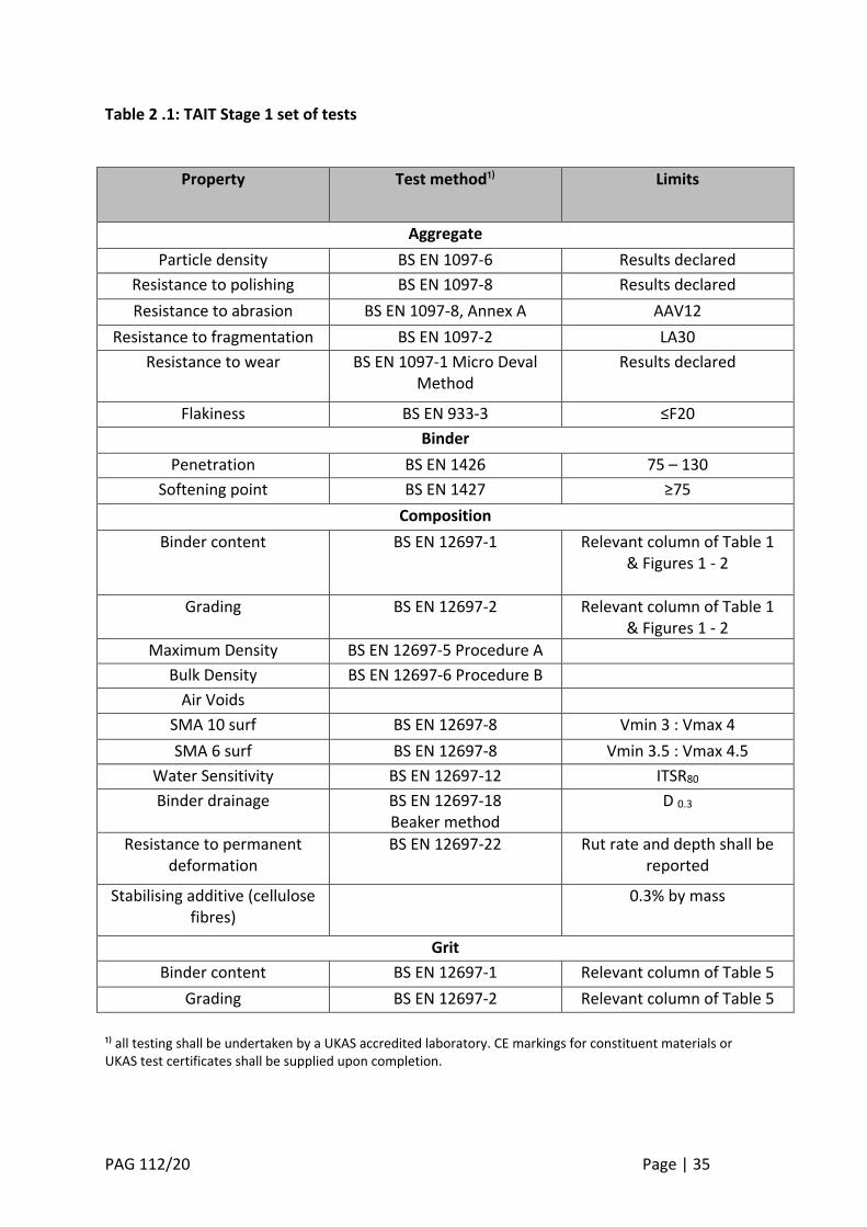
Table 2 .1: TAIT Stage 1 set of tests
Property
Test method¹⁾ Limits
Aggregate
Particle density BS EN 1097-6 Results declared
Resistance to polishing BS EN 1097-8 Results declared
Resistance to abrasion BS EN 1097-8, Annex A AAV12
Resistance to fragmentation BS EN 1097-2 LA30
Resistance to wear BS EN 1097-1 Micro Deval Method
Results declared
Flakiness BS EN 933-3 ≤F20
Binder
Penetration BS EN 1426 75 – 130
Softening point BS EN 1427 ≥75
Composition
Binder content BS EN 12697-1 Relevant column of Table 1 & Figures 1 - 2
Grading BS EN 12697-2 Relevant column of Table 1 & Figures 1 - 2
Maximum Density BS EN 12697-5 Procedure A
Bulk Density BS EN 12697-6 Procedure B
Air Voids
SMA 10 surf BS EN 12697-8 Vmin 3 : Vmax 4
SMA 6 surf BS EN 12697-8 Vmin 3.5 : Vmax 4.5
Water Sensitivity BS EN 12697-12 ITSR80
Binder drainage BS EN 12697-18 Beaker method
D 0.3
Resistance to permanent deformation
BS EN 12697-22 Rut rate and depth shall be reported
Stabilising additive (cellulose fibres)
0.3% by mass
Grit
Binder content BS EN 12697-1 Relevant column of Table 5
Grading BS EN 12697-2 Relevant column of Table 5
¹⁾ all testing shall be undertaken by a UKAS accredited laboratory. CE markings for constituent materials or UKAS test certificates shall be supplied upon completion.
PAG 112/20 Page | 36
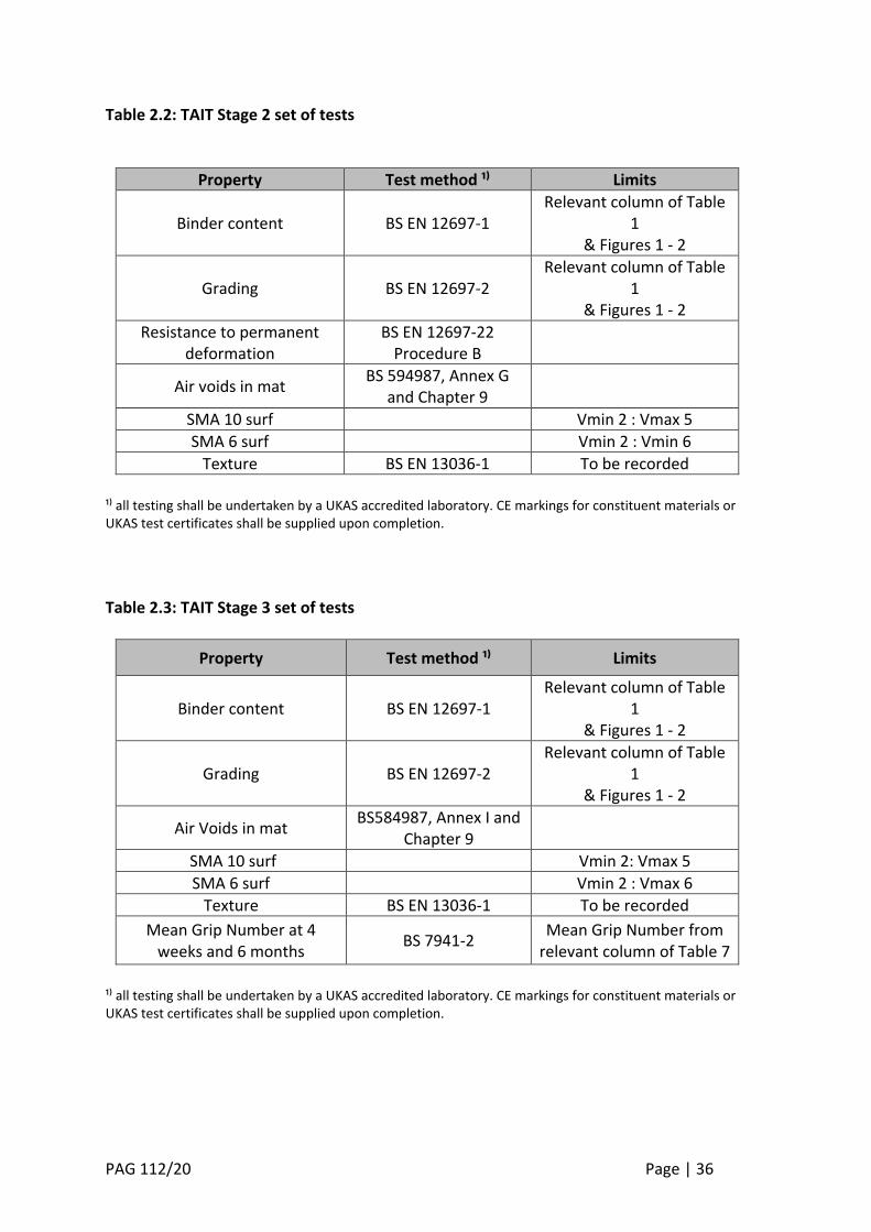
Table 2.2: TAIT Stage 2 set of tests
Property Test method ¹⁾ Limits
Binder content BS EN 12697-1 Relevant column of Table
1 & Figures 1 - 2
Grading BS EN 12697-2 Relevant column of Table
1 & Figures 1 - 2
Resistance to permanent deformation
BS EN 12697-22 Procedure B
Air voids in mat BS 594987, Annex G
and Chapter 9
SMA 10 surf Vmin 2 : Vmax 5
SMA 6 surf Vmin 2 : Vmin 6
Texture BS EN 13036-1 To be recorded
¹⁾ all testing shall be undertaken by a UKAS accredited laboratory. CE markings for constituent materials or UKAS test certificates shall be supplied upon completion.
Table 2.3: TAIT Stage 3 set of tests
Property Test method ¹⁾ Limits
Binder content BS EN 12697-1 Relevant column of Table
1 & Figures 1 - 2
Grading BS EN 12697-2 Relevant column of Table
1 & Figures 1 - 2
Air Voids in mat BS584987, Annex I and
Chapter 9
SMA 10 surf Vmin 2: Vmax 5
SMA 6 surf Vmin 2 : Vmax 6
Texture BS EN 13036-1 To be recorded
Mean Grip Number at 4 weeks and 6 months
BS 7941-2 Mean Grip Number from
relevant column of Table 7
¹⁾ all testing shall be undertaken by a UKAS accredited laboratory. CE markings for constituent materials or UKAS test certificates shall be supplied upon completion.
PAG 112/20 Page | 37
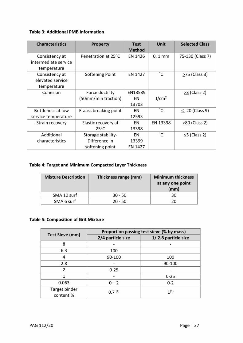
Table 3: Additional PMB Information
Characteristics
Property Test Method
Unit Selected Class
Consistency at intermediate service
temperature
Penetration at 25oC EN 1426 0, 1 mm 75-130 (Class 7)
Consistency at elevated service
temperature
Softening Point EN 1427 °C >75 (Class 3)
Cohesion Force ductility (50mm/min traction)
EN13589 EN
13703
J/cm2
>3 (Class 2)
Brittleness at low service temperature
Fraass breaking point EN 12593
°C ≤- 20 (Class 9)
Strain recovery Elastic recovery at 25oC
EN 13398
EN 13398 >80 (Class 2)
Additional characteristics
Storage stability- Difference in
softening point
EN 13399
EN 1427
°C ≤5 (Class 2)
Table 4: Target and Minimum Compacted Layer Thickness
Mixture Description Thickness range (mm) Minimum thickness at any one point
(mm)
SMA 10 surf 30 - 50 30
SMA 6 surf 20 - 50 20
Table 5: Composition of Grit Mixture
Test Sieve (mm) Proportion passing test sieve (% by mass)
2/4 particle size 1/ 2.8 particle size
8 - -
6.3 100 -
4 90-100 100
2.8 - 90-100
2 0-25 -
1 - 0-25
0.063 0 – 2 0-2
Target binder content %
0.7 (1) 1(1)
PAG 112/20 Page | 38
(1) The binder used to coat the grit shall be 40/60 grade conforming to BS EN 12591. The tolerance on the target binder content as shown in Table 5 shall be ± 0.3%.
Table 6: Rate of spread of coated grit
Nominal aggregate size (mm) Rate of spread (kg/m³)
SMA 10 surf 0.7 – 0.9
SMA 6 surf 0.5 – 0.7
Table 7: TAIT Stage 3 minimum Grip-Number (GN) after trafficking
Site Class CS 228 Site Category
Table 4.2 (DMRB 7.3.1)
After four weeks After six months
1 A, B & C 0.39 0.51
2 R, G1 & S1 0.51 0.62
3 Q, K, G2 & S2 0.56 0.67
Table 8: Texture Depth Guidance
Nominal Aggregate Size (mm)
Texture Range (mm)
SMA 10 surf 0.8 – 1.3
SMA 6 surf 0.7 – 1.1
Table 9: Limitations on placement in respect of weather
Surfacing Air Temperature Receiving Course
30mm – 50mm layer thickness
Falling temperature Stop at 0°C unless calm and dry in which case stop at -2°C Rising temperature Start at 0°C
Must be free of standing water, snow or ice
< 30 mm layer thickness Only start at minimum air temperature of 5°C
Must be free of standing water, snow or ice
PAG 112/20 Page | 39
Stage 2 Relaxation
Figure 3: TAIT Process
Stage One
Stage Two
Stage Three
Laboratory Validation
Amend DesignCompliant with
Table 2.1
Product mix trial
Yes
Compliant with Table 2.2
Alternative plant – Compliant with Cl
5.3.9
Alternative aggregate source – Compliant
with Cl 5.3.10
No
Network level trial
Yes
Yes Yes
Compliant with Table 2.2
Approved for use on the Motorway and Trunk Road Network in Wales
Yes
No
No
No
No
PAG 112/20 Page | 40
Figure 4: TAIT Stage 2 sampling plan
PAG 112/20 Page | 41
10. Example of Approval Certificate Template Mixture Specification: BS EN 13108-5 Mixture Identification Code: e.g. 5019 Mixture Designation: e.g. SMA 6 Surf 75-130-75 PSV 56
Supplier A N Other
Mixing Plant N Where
Course Aggregate As per Cl 4.2.2.1 / Source and Rock Type
Fine Aggregate As per Cl 4.2.2.2 / Source and Rock Type