CHPRC-03760 Revision 0 WESF Modifications Final Design Report (Project W-135) Prepared for the U.S. Department of Energy Assistant Secretary for Environmental Management Contractor for the U.S. Department of Energy under Contract DE-AC06-08RL14788 P.O. Box 1600 Richland, Washington 99352 Approved for Public Release; Further Dissemination Unlimited
Transcript
CHPRC-03760Revision 0
WESF Modifications Final Design Report (ProjectW-135)
Prepared for the U.S. Department of EnergyAssistant Secretary for Environmental Management
Contractor for the U.S. Department of Energyunder Contract DE-AC06-08RL14788
P.O. Box 1600 Richland, Washington 99352
Approved for Public Release; Further Dissemination Unlimited
Prepared for the U.S. Department of Energy Assistant Secretary for Environmental Management
Contractor for the U.S. Department of Energyunder Contract DE-AC06-08RL14788
P.O. Box 1600 Richland, Washington 99352
Release Approval Date Release Stamp
Approved for Public Release; Further Dissemination Unlimited
By Janis D. Aardal at 11:05 am, Jun 17, 2019
Jun 17, 2019DATE:
CHPRC-03760Revision 0
TRADEMARK DISCLAIMERReference herein to any specific commercial product, process, or service bytradename, trademark, manufacturer, or otherwise, does not necessarilyconstitute or imply its endorsement, recommendation, or favoring by theUnited States Government or any agency thereof or its contractors orsubcontractors.
This report has been reproduced from the best available copy.
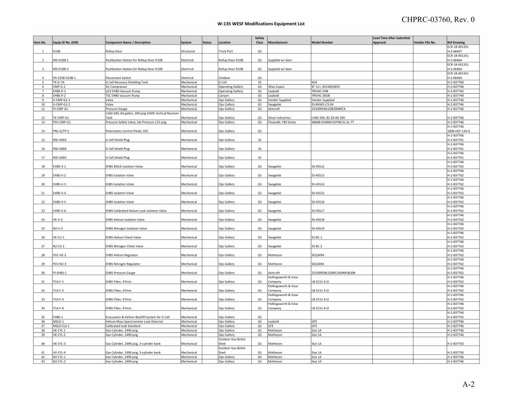
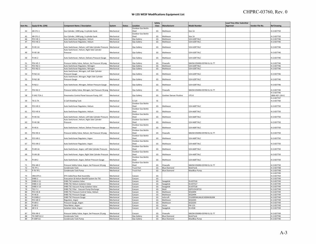
59 TK‐G‐7A G Cell Shielding Tank Mechanical G Cell SSH‐2‐837747H‐2‐837760
60 PCV‐HE‐5 Auto Switchover Regulator, Helium MechanicalOutdoor Gas Bottle Shed GS Matheson 524‐A68T7ALC H‐2‐837750
61 PCV‐HE‐6 Auto Switchover Regulator, Helium MechanicalOutdoor Gas Bottle Shed GS Matheson 524‐A68T7ALC H‐2‐837750
62 PI‐HE‐5A Auto Switchover, Helium, Left Side Cylinder Pressure MechanicalOutdoor Gas Bottle Shed GS Matheson 524‐A68T7ALC H‐2‐837750
63 PI‐HE‐5BAuto Switchover, Helium, Right Side Cylinder Pressure Mechanical
Outdoor Gas Bottle Shed GS Matheson 524‐A68T7ALC H‐2‐837750
64 PI‐HE‐6 Auto Switchover, Helium, Deliver Pressure Gauge MechanicalOutdoor Gas Bottle Shed GS Matheson 524‐A68T7ALC H‐2‐837750
65 PSV‐HE‐6 Pressure Safety Valve, Helium, Set Pressure 50 psig MechanicalOutdoor Gas Bottle Shed GS Flowsafe S842M‐05MN0‐05FN0‐SL‐SL‐TT H‐2‐837750
66 PCV‐AR‐1 Auto Switchover Regulator, Argon MechanicalOutdoor Gas Bottle Shed GS Matheson 524‐A68T7ALC H‐2‐837750
67 PCV‐AR‐2 Auto Switchover Regulator, Argon MechanicalOutdoor Gas Bottle Shed GS Matheson 524‐A68T7ALC H‐2‐837750
68 PI‐AR‐1A Auto Switchover, Argon, Left Side Cylinder Pressure MechanicalOutdoor Gas Bottle Shed GS Matheson 524‐A68T7ALC H‐2‐837750
69 PI‐AR‐1B Auto Switchover, Argon, Right Side Cylinder Pressure MechanicalOutdoor Gas Bottle Shed GS Matheson 524‐A68T7ALC H‐2‐837750
70 PI‐AR‐2 Auto Switchover, Argon, Deliver Pressure Gauge MechanicalOutdoor Gas Bottle Shed GS Matheson 524‐A68T7ALC H‐2‐837750
71 PSV‐AR‐2 Pressure Safety Valve, Argon, Set Pressure 50 psig MechanicalOutdoor Gas Bottle Shed GS Flowsafe S842M‐05MN0‐05FN0‐SL‐SL‐TT H‐2‐837750
72 TK‐TP‐1 Condensate Tank Mechanical Truck Port GS Blue Diamond MultiTank H‐2‐83774873 P‐TK‐TP1 Condensate Tank Pump Mechanical Truck Port GS Blue Diamond MaxiBlue Pump H‐2‐837748
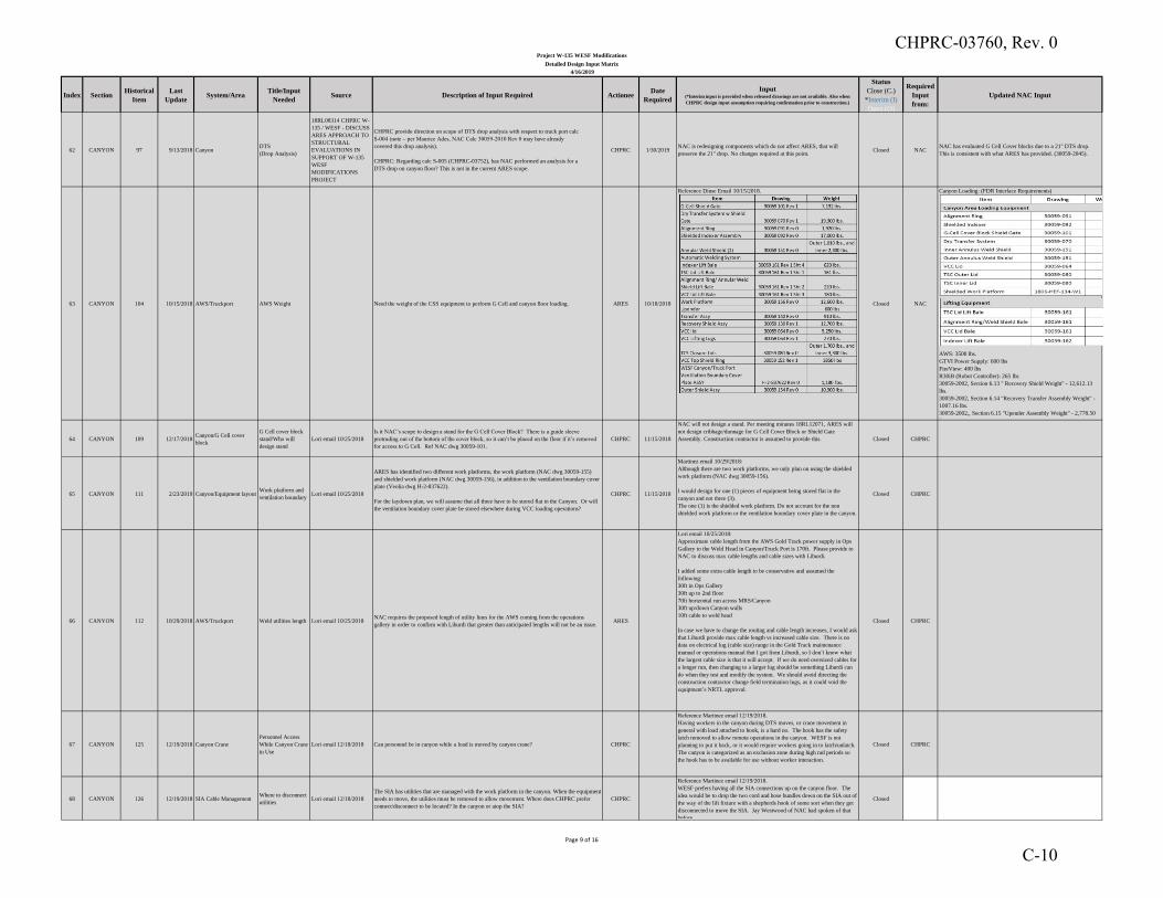
Is it NAC’s scope to design a stand for the G Cell Cover Block? There is a guide sleeve
protruding out of the bottom of the cover block, so it can’t be placed on the floor if it’s removed
for access to G Cell. Ref NAC dwg 30059-101.
CHPRC 11/15/2018
NAC will not design a stand. Per meeting minutes 18RL12071, ARES will
not design cribbage/dunnage for G Cell Cover Block or Shield Gate
Assembly. Construction contractor is assumed to provide this. Closed CHPRC
65 CANYON 111 2/23/2019 Canyon/Equipment layoutWork platform and
ventilation boundaryLori email 10/25/2018
ARES has identified two different work platforms, the work platform (NAC dwg 30059-155)
and shielded work platform (NAC dwg 30059-156), in addition to the ventilation boundary cover
plate (Veolia dwg H-2-837622).
For the laydown plan, we will assume that all three have to be stored flat in the Canyon. Or will
the ventilation boundary cover plate be stored elsewhere during VCC loading operations?
CHPRC 11/15/2018
Martinez email 10/29/2018:
Although there are two work platforms, we only plan on using the shielded
work platform (NAC dwg 30059-156).
I would design for one (1) pieces of equipment being stored flat in the
canyon and not three (3).
The one (1) is the shielded work platform. Do not account for the non
shielded work platform or the ventilation boundary cover plate in the canyon.
Closed CHPRC
66 CANYON 112 10/29/2018 AWS/Truckport Weld utilities length Lori email 10/25/2018NAC requires the proposed length of utility lines for the AWS coming from the operations
gallery in order to confirm with Liburdi that greater than anticipated lengths will not be an issue.ARES
Lori email 10/25/2018:
Approximate cable length from the AWS Gold Track power supply in Ops
Gallery to the Weld Head in Canyon/Truck Port is 170ft. Please provide to
NAC to discuss max cable lengths and cable sizes with Liburdi.
I added some extra cable length to be conservative and assumed the
following:
30ft in Ops Gallery
30ft up to 2nd floor
70ft horizontal run across MRS/Canyon
30ft up/down Canyon walls
10ft cable to weld head
In case we have to change the routing and cable length increases, I would ask
that Liburdi provide max cable length vs increased cable size. There is no
data on electrical lug (cable size) range in the Gold Track maintenance
manual or operations manual that I got from Liburdi, so I don’t know what
the largest cable size is that it will accept. If we do need oversized cables for
a longer run, then changing to a larger lug should be something Liburdi can
do when they test and modify the system. We should avoid directing the
construction contractor change field termination lugs, as it could void the
equipment’s NRTL approval.
Closed CHPRC
67 CANYON 125 12/19/2018 Canyon Crane
Personnel Access
While Canyon Crane
in Use
Lori email 12/18/2018 Can personnel be in canyon while a load is moved by canyon crane? CHPRC
Reference Martinez email 12/19/2018.
Having workers in the canyon during DTS moves, or crane movement in
general with load attached to hook, is a hard no. The hook has the safety
latch removed to allow remote operations in the canyon. WESF is not
planning to put it back, or it would require workers going in to latch/unlatch.
The canyon is categorized as an exclusion zone during high rad periods so
the hook has to be available for use without worker interaction.
Closed CHPRC
68 CANYON 126 12/19/2018 SIA Cable ManagementWhere to disconnect
utilitiesLori email 12/18/2018
The SIA has utilities that are managed with the work platform in the canyon. When the equipment
needs to move, the utilities must be removed to allow movement. Where does CHPRC prefer
connect/disconnect to be located? In the canyon or atop the SIA?
CHPRC
Reference Martinez email 12/19/2018.
WESF prefers having all the SIA connections up on the canyon floor. The
idea would be to drop the two cord and hose bundles down on the SIA out of
the way of the lift fixture with a shepherds hook of some sort when they get
disconnected to move the SIA. Jay Westwood of NAC had spoken of that
before.
Closed
Page 9 of 16
CHPRC-03760, Rev. 0
C-10
Index SectionHistorical
Item
Last
UpdateSystem/Area
Title/Input
NeededSource Description of Input Required Actionee
Date
Required
Input(*Interim input is provided when released drawings are not available. Also when
CHPRC design input assumption requiring confirmation prior to construction.)
Status
Close (C.)
*Interim (I)
Open (O)
Required
Input
from:
Updated NAC Input
Project W-135 WESF Modifications
Detailed Design Input Matrix
4/16/2019
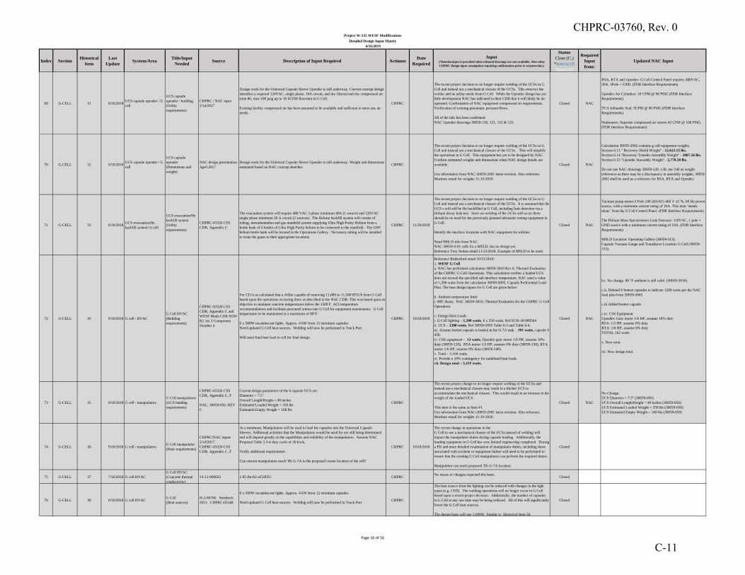
69 G-CELL 31 9/10/2018UCS capsule upender / G
cell
UCS capsule
upender / building
(Utility
requirements)
CHPRC / NAC input
2/14/2017
Design work for the Universal Capsule Sleeve Upender is still underway. Current concept design
identifies a required 120VAC, single phase, 10A circuit, and dry filtered and dry compressed air
(min 80, max 100 psig up to 10 SCFM flowrate) in G Cell.
Existing facility compressed air has been assumed to be available and sufficient to meet any air
needs.
CHPRC
The recent project decision to no longer require welding of the UCSs in G
Cell and instead use a mechanical closure of the UCSs. This removes the
welder and its utility needs from G Cell. While the Upender design has yet
little development NAC has indicated in their CDR that it will likely be air
operated. Confirmation of NAC equipment compressed air requirements.
Verification of existing pneumatic pressure/flows.
All of the info has been confirmed.
NAC Upender drawings 30059-120, 121, 122 & 123.
Closed NAC
RSA, RTA and Upender: G Cell Control Panel requires 480VAC,
30A, 3Pole + GND. (FDR Interface Requirements)
Upender Air Cylinders: 10 CFM @ 90 PSIG (FDR Interface
Do not use NAC drawings 30059-120, 130, nor 140 as weight
references as there may be a discrepancy in assembly weights. 30059-
2002 shall be used as a reference for RSA, RTA and Upender.
112 G-CELL 129 1/22/2019 G Cell Service Plugs Use of Service Plugs
How many of the service plugs would CHPRC like to be utilized. There are currently 4 available.
Design for NAC equipment requires 18 total lines. 16 are pneumatic lines routed through 2
service plugs. Each service plug has 8 penetrations. The last two air lines are vacuum, helium and
nitrogen lines, these have their own service plug.
CHPRC would like to have the fourth service plug be included in the FMP's
for design and have 8 spare penetrations.
The NAC addition of shielding on the upender will require two air lines to
drive the shielding in place and move out of place. Provisions for these air
lines are to be taken.
Closed
113 G-CELL 131 1/23/2019 G Cell Control PanelsE-Stops and G Cell
door interlock
Will control panels need to accommodate an emergency stop for NAC equipment, along with an
interlock for NAC equipment with door.
Emergency stop will not be incorporated into design, current design does not
allow for equipment to run unless control buttons are depressed.
No interlock for G-Cell door is required since equipment will not operate
unless an operator deliberately operates equipment.
Closed
114 G-CELL 133 2/5/2019 Pictures and dimensions of penetrations throughout G Cell are required to advance design. Muller provided images 2/5/2019. Closed
115 POOL CELL 53 7/10/2018 Pool cell hoist/ pool cellPool cell hoist
requirements
WESF Modifications
FDC, CHPRC-03011,
Rev 1,
Acceptability of the crane to lift desired loads should be verified early in the project. Further
details on the pool cell crane, including design basis codes and standards, are provided in HWS-
8951 Division X.
CHPRC Pool cell crane will not be used for this project. Closed CHPRC
116 MISC 54 7/10/2018 MCSC projectInstrumentation
requirements Requirements unknown at this time CHPRC 8/15/2018
This question has been asked in several places throughout this design input
matrixClosed
117 MISC 55 7/10/2018MCSC project/WESF
ventilation system
WESF air permit
(Are changes to the
air permit required)
WESF Modifications
FDC, CHPRC-03011,
Rev 1.
If modifications to the ventilation system are required, CHPRC shall determine if changes to the
facility air permit are required.CHPRC 11/15/2018
This is not a design issue.
Any modifications will undergo a review process. If air permits are required,
then the ECO will inquire about this with Ecology.
Closed
118 MISC 56 7/10/2018 MCSC project
ALARA
(Implementation in
design)
WESF Modifications
FDC, CHPRC-03011,
Rev 1.
As low as reasonably achievable (ALARA) principals shall be applied for any worker activity
with the potential of dose and contamination exposure. In the course of application of these
ALARA principles, the project will ensure radiation exposures to workers and the public, and
releases of radioactivity to the
environment, are maintained below regulatory limits and deliberate efforts are taken to further
reduce exposures and releases as low as reasonably achievable. Design considerations shall
include contamination control, shielding, remote activities, failure recovery, and maintenance.
CHPRC 9/1/2018
It was noted that ALARA is being followed as a normal course of the design
process. ALARA will be addressed in the narrative of the PDR as well.
Reference CHPRC-03593 latest Revision (Rev. 1), ALARA Plan.
Closed
119 MISC 57 9/10/2018 MCSC project
Recovery procedures
(Development of
procedures)
Recovery procedures should be developed to provide a recovery path should a normal procedure
encounter an off-normal situation.CHPRC
This is not applicable to design (CHPRC activity).
Recovery procedures will be developed during Mockup efforts. Also NAC
MPC-CSS FMEA will be used to develop the procedures. The FES schedule
is currently tracking this activity.
Closed
120 MISC 59 12/18/2018 UCS storage
UCS storage
(Design od storage
racks)
1. CHPRC to provide guidance as to how many/type of racks needed in Service Gallery for
storage of empty UCS. Also provide any specific features desired in the design of UCS storage
racks and spacer storage racks.CHPRC 12/13/2018
Construction specification to be developed by ARES with help from
CHPRC.
Requirements:
• Space to stage 22-25 UCS's, 5 type W UCS's and 5 spacer capsules.
• Made from non-combustible material that will not chemically contaminate
stainless steel UCSs
• Prevent UCSs from falling, stored in vertical position
• Accessibility by hand cart
• Covering to prevent foreign debris for both UCSs and capsule spacers
• Must fit within a 8'x3' foot print
• Must be lockable
• Room for a UCS gauging tool
• Contents contained in a combustible storage area
Presentation 9/4/2019Is there a need for HEPA filters in vacuum lines when pulling from rad to non-rad locations? CHPRC 10/18/2018
Input: No HEPA filtration required for any service air lines to NAC
equipment.
G Cell:
Vacuum and MSLD, along with exhaust as necessary, require TWO HEPA
filters in line vertically mounted.
The LB-5211 A-O filters are available in a variety of diameters; we want the
47-mm diameter filters (the thickness is 0.38 mm).
Canyon:
Vacuum pump requires HEPA filtration on the exhaust.
Closed CHPRC
126 MISC 95 9/13/2018 WESF HVAC
HVAC
(Power Outage
evaluation)
WESF Mods CDR SOW
R2 ATT3 Component
Number 6
1. CHPRC to provide guidance regarding ventilation system design requirements related to
protection against unanticipated outages.
(i) Truck Port
(ii) G Cell
(iii) Canyon
Notes:
(a) Basis ventilation and or cooling outage could occur as a result of maintenance or power
outages. W-135 should evaluate if system outage is acceptable for safety or planned outage.
(b) The results could cause ventilation or cooling to become important to safety, and possibly
require they be included with emergency power supply.
(c) A requirement to provide emergency power to either of these systems would invalidate an
Electrical Load assumption (LEMS-MCSC-17-CAL-006 rev 0, 3.0 A) No MCSC loads must be
connected to WESF emergency electrical power busses.
CHPRC 12/13/2018
1. Inputs:
(i) Truck Port: WESF Mods to provide redundant HVAC system with
backup power where feasible and practical. Components shall be AG-1
compliant or undergo CGD process. Design shall be in compliance with
DOE 420.1C. Three, ten ton outdoor heat pump units will be provided for
Truck Port and Canyon cooling. Two units are required the third is for
redundancy. Six wall-mounted heat exchanger units will be provided for
Truck Port cooling. Five are required one is for redundancy.
(ii) G Cell: WESF Mods to provide HVAC system with backup power
where feasible and practical. No redundancy. Components shall be AG-1
compliant or undergo CGD process. Design shall be in compliance with
DOE 420.1C.
(iii) Canyon: No additional measures required, unless redundancy in the
truckport cannot be separated from the canyon, then redundancy would need
to be incorporated as necessary.
See Tyler Crumpley email 12/20/2018 for redundancy discussion.
Action:
(i) CHPRC to work with ARES to assess if a solution short of 100%
redundancy would provide near equivalent protection.
Closed CHPRC
127 MISC 124 1/9/2019 WESF HVACCondensate Lines
Locations
12/18/2018 ARES
8:00AM meeting
WASLH requires location of condensate line inside of WESF truckport.
Also must ensure chiller condensate in G-Cell and Canyon are drained to the appropriate
locations.CHPRC 12/30/2018
Input:
Condensate drainage to TK-100 is not a viable option.
Condensate drainage to pool cell 9 or 10 is not a viable option.
Path forward based on 1/22/2019 walk down with WESF Operations and
Engineering is to provide space outside near the gas storage shed being
designed by ARES and have a heat trace on the lines to help with freezing.
Route condensate lines from within WESF through wall to the collection
tank. The tank(s) should be sized for 500 gallons with freeze protection.
Closed CHPRC
128 MISC 96 9/13/2018Geotechnical Report
RHO-R-25
Geotech report
(Provide feedback)
18RL08314 CHPRC W-
135 / WESF - DISCUSS
ARES APPROACH TO
STRUCTURAL
EVALUATIONS IN
SUPPORT OF W-135
WESF
MODIFICATIONS
PROJECT
CHPRC will review RHO-R-25 geotechnical report and provide ARES with any
feedback/comments/concerns.CHPRC 12/13/2018
Reference Martinez email 12/10/2018.
No comments or concerns where RHO-R-25 has been used by ARES.Closed
129 MISC 99 9/19/2018WESF/Outside Pad Near
Truck Port
Existing Vacuum
Pump Pad
(Can pad be cleared
of old equipment)
ARES 8:00AM weekly
meeting. 9/11/2018
Can vacuum pumps PAS-1 and PAS-2 be removed from existing pad outside of the truck port
area?CHPRC 10/4/2018
The vacuum pumps on the south side of WESF (PAS-1 & and PAS-2) have
been deactivated and shall be removed By W-135.Closed CHPRC
Page 15 of 16
CHPRC-03760, Rev. 0
C-16
Index SectionHistorical
Item
Last
UpdateSystem/Area
Title/Input
NeededSource Description of Input Required Actionee
Date
Required
Input(*Interim input is provided when released drawings are not available. Also when
CHPRC design input assumption requiring confirmation prior to construction.)
Status
Close (C.)
*Interim (I)
Open (O)
Required
Input
from:
Updated NAC Input
Project W-135 WESF Modifications
Detailed Design Input Matrix
4/16/2019
130 MISC 107 10/24/2018 WESF/Outside
Location of Helium
Bottles for
TSC/EHBS
Where will helium bottles needed for TSC/EHBS activities be located? And what design is
necessary?CHPRC 10/4/2018
The location of the Helium bottles has been confirmed to be as currently
shown. The change is to remove the gas storage enclosure and to call out for
off-the-shelf gas bottle racks fully enclosed. This outside location will
require that we account for temperature differences between outside and
inside. We will be adding this temperature difference into the FDC rev. 3
document.
Closed CHPRC
131 MISC 117 11/26/2018 NAC EquipmentTemperature for
NAC Equipment
Temperatures above 90°C (200°F) require specialty wire. What areas inside of WESF will be
above these temperatures?CHPRC 11/29/2018
Per NAC 30059-3001, 3005 and 3010. Use the following temperature values
for the surface:
*UCS - 450°F
*Upender - 450°F
*RSA - 450°F
*DTS - 300°F
*VCC - 250°F
Closed NAC
NO CHANGE
UCS - 450°F (30059-2015)
Upender - 450°F (30059-2015)
RSA - 450°F (30059-3010)
DTS - 300°F (30059-3005)
VCC - 250°F 30059-3001)
132 MISC 123 12/17/2018 Entire WESF Lighting evaluation For camera design, lighting evaluation of G Cell, Canyon and Truckport is required. CHPRC 12/17/2018Lighting evaluations were sent per email 12/04/2018. Martinez email
12/04/2018.Closed
133 MISC 130 1/22/2019 Entire WESF Safety Classification Safety Classification for equipment is desired.
Input: Reference CHPRC_03831 (SEL) sent per Wilson email 1/31/2019.
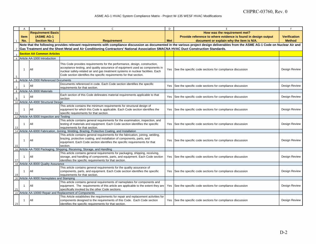
Requirement Basis (ASME AG-1 Section No.) Requirement Met
How was the requirement met?Provide reference to where evidence is found in design output
document or explain why the item is N/A.Verification
Method
Section AA Common ArticlesArticle AA-1000 Introduction
1 All
This Code provides requirements for the performance, design, construction, acceptance testing, and quality assurance of equipment used as components in nuclear safety-related air and gas treatment systems in nuclear facilities. Each Code section identifies the specific requirements for that section.
Yes See the specific code sections for compliance discussion Design Review
Article AA-2000 Referenced Documents
1 All Documents referenced in code. Each Code section identifies the specific requirements for that section. Yes See the specific code sections for compliance discussion Design Review
Article AA-3000 Materials
1 All Each section of this Code delineates material requirements applicable to that section Yes See the specific code sections for compliance discussion Design Review
Article AA-4000 Structural Design
1 AllThis article contains the minimum requirements for structural design of equipment for which this Code is applicable. Each Code section identifies the specific requirements for that section.
Yes See the specific code sections for compliance discussion Design Review
Article AA-5000 Inspection and Testing
1 AllThis article contains general requirements for the examination, inspection, and testing of materials and equipment. Each Code section identifies the specific requirements for that section.
Yes See the specific code sections for compliance discussion Design Review
Article AA-6000 Fabrication, Joining, Welding, Brazing, Protective Coating, and Installation
1 All
This article contains general requirements for the fabrication, joining, welding, brazing, protective coating, and installation of components, parts, and equipment. Each Code section identifies the specific requirements for that section.
Yes See the specific code sections for compliance discussion Design Review
Article AA-7000 Packaging, Shipping, Receiving, Storage, and Handling
1 AllThis article contains general requirements for packaging, shipping, receiving, storage, and handling of components, parts, and equipment. Each Code section identifies the specific requirements for that section.
Yes See the specific code sections for compliance discussion Design Review
Article AA-8000 Quality Assurance
1 AllThis article contains general requirements for the quality assurance of components, parts, and equipment. Each Code section identifies the specific requirements for that section.
Yes See the specific code sections for compliance discussion Design Review
Article AA-9000 Nameplates and Stamping
1 AllThis article contains general requirements of nameplates for components and equipment. The requirements of this article are applicable to the extent they are specifically invoked by the other Code sections.
Yes See the specific code sections for compliance discussion Design Review
Article AA-10000 Repair and Replacement of Components
1 AllThis Article establishes the requirements for repair and replacement activities for components designed to the requirements of this Code. Each Code section identifies the specific requirements for that section.
Yes See the specific code sections for compliance discussion Design Review
Note that the following provides relevant requirements with compliance discussion as documented in the various project design deliverables from the ASME AG-1 Code on Nuclear Air and Gas Treatment and the Sheet Metal and Air Conditioning Contractors' National Association SMACNA HVAC Duct Construction Standards.
Requirement Basis (ASME AG-1 Section No.) Requirement Met
How was the requirement met?Provide reference to where evidence is found in design output
document or explain why the item is N/A.Verification
Method
24
25
26
27
28
29
30
31
32
33
34
35
36
37
38
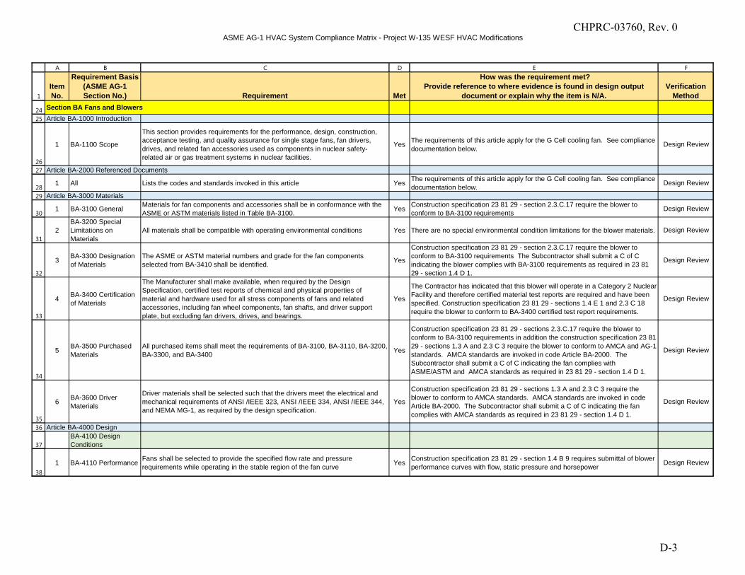
Section BA Fans and BlowersArticle BA-1000 Introduction
1 BA-1100 Scope
This section provides requirements for the performance, design, construction, acceptance testing, and quality assurance for single stage fans, fan drivers, drives, and related fan accessories used as components in nuclear safety-related air or gas treatment systems in nuclear facilities.
Yes The requirements of this article apply for the G Cell cooling fan. See compliance documentation below.
Design Review
Article BA-2000 Referenced Documents
1 All Lists the codes and standards invoked in this article Yes The requirements of this article apply for the G Cell cooling fan. See compliance documentation below. Design Review
Article BA-3000 Materials
1 BA-3100 General Materials for fan components and accessories shall be in conformance with the ASME or ASTM materials listed in Table BA-3100. Yes Construction specification 23 81 29 - section 2.3.C.17 require the blower to
conform to BA-3100 requirements Design Review
2BA-3200 Special Limitations on Materials
All materials shall be compatible with operating environmental conditions Yes There are no special environmental condition limitations for the blower materials. Design Review
3 BA-3300 Designation of Materials
The ASME or ASTM material numbers and grade for the fan components selected from BA-3410 shall be identified. Yes
Construction specification 23 81 29 - section 2.3.C.17 require the blower to conform to BA-3100 requirements The Subcontractor shall submit a C of C indicating the blower complies with BA-3100 requirements as required in 23 81 29 - section 1.4 D 1.
Design Review
4 BA-3400 Certification of Materials
The Manufacturer shall make available, when required by the Design Specification, certified test reports of chemical and physical properties of material and hardware used for all stress components of fans and related accessories, including fan wheel components, fan shafts, and driver support plate, but excluding fan drivers, drives, and bearings.
Yes
The Contractor has indicated that this blower will operate in a Category 2 Nuclear Facility and therefore certified material test reports are required and have been specified. Construction specification 23 81 29 - sections 1.4 E 1 and 2.3 C 18 require the blower to conform to BA-3400 certified test report requirements.
Design Review
5 BA-3500 Purchased Materials
All purchased items shall meet the requirements of BA-3100, BA-3110, BA-3200, BA-3300, and BA-3400 Yes
Construction specification 23 81 29 - sections 2.3.C.17 require the blower to conform to BA-3100 requirements in addition the construction specification 23 81 29 - sections 1.3 A and 2.3 C 3 require the blower to conform to AMCA and AG-1 standards. AMCA standards are invoked in code Article BA-2000. The Subcontractor shall submit a C of C indicating the fan complies with ASME/ASTM and AMCA standards as required in 23 81 29 - section 1.4 D 1.
Design Review
6 BA-3600 Driver Materials
Driver materials shall be selected such that the drivers meet the electrical and mechanical requirements of ANSI /IEEE 323, ANSI /IEEE 334, ANSI /IEEE 344, and NEMA MG-1, as required by the design specification.
Yes
Construction specification 23 81 29 - sections 1.3 A and 2.3 C 3 require the blower to conform to AMCA standards. AMCA standards are invoked in code Article BA-2000. The Subcontractor shall submit a C of C indicating the fan complies with AMCA standards as required in 23 81 29 - section 1.4 D 1.
Design Review
Article BA-4000 DesignBA-4100 Design Conditions
1 BA-4110 Performance Fans shall be selected to provide the specified flow rate and pressure requirements while operating in the stable region of the fan curve Yes Construction specification 23 81 29 - section 1.4 B 9 requires submittal of blower
performance curves with flow, static pressure and horsepower Design Review
Requirement Basis (ASME AG-1 Section No.) Requirement Met
How was the requirement met?Provide reference to where evidence is found in design output
document or explain why the item is N/A.Verification
Method
39
40
41
42
43
44
45
46
47
48
49
50
51
52
53
54
55
56
57
58
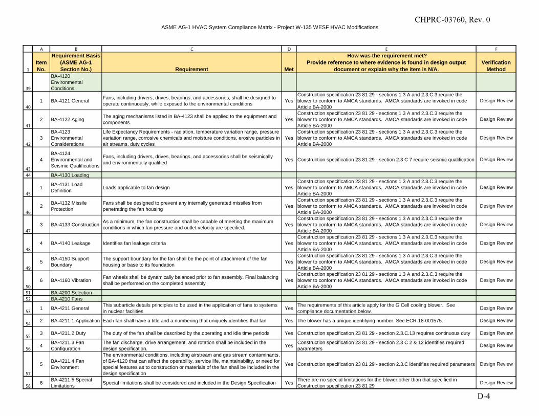
BA-4120 Environmental Conditions
1 BA-4121 General Fans, including drivers, drives, bearings, and accessories, shall be designed to operate continuously, while exposed to the environmental conditions Yes
Construction specification 23 81 29 - sections 1.3 A and 2.3.C.3 require the blower to conform to AMCA standards. AMCA standards are invoked in code Article BA-2000
Design Review
2 BA-4122 Aging The aging mechanisms listed in BA-4123 shall be applied to the equipment and components Yes
Construction specification 23 81 29 - sections 1.3 A and 2.3.C.3 require the blower to conform to AMCA standards. AMCA standards are invoked in code Article BA-2000
Design Review
3BA-4123 Environmental Considerations
Life Expectancy Requirements - radiation, temperature variation range, pressure variation range, corrosive chemicals and moisture conditions, erosive particles in air streams, duty cycles
YesConstruction specification 23 81 29 - sections 1.3 A and 2.3.C.3 require the blower to conform to AMCA standards. AMCA standards are invoked in code Article BA-2000
Design Review
4BA-4124 Environmental and Seismic Qualifications
Fans, including drivers, drives, bearings, and accessories shall be seismically and environmentally qualified Yes Construction specification 23 81 29 - section 2.3 C 7 require seismic qualification Design Review
BA-4130 Loading
1 BA-4131 Load Definition Loads applicable to fan design Yes
Construction specification 23 81 29 - sections 1.3 A and 2.3.C.3 require the blower to conform to AMCA standards. AMCA standards are invoked in code Article BA-2000
Design Review
2 BA-4132 Missile Protection
Fans shall be designed to prevent any internally generated missiles from penetrating the fan housing Yes
Construction specification 23 81 29 - sections 1.3 A and 2.3.C.3 require the blower to conform to AMCA standards. AMCA standards are invoked in code Article BA-2000
Design Review
3 BA-4133 Construction As a minimum, the fan construction shall be capable of meeting the maximum conditions in which fan pressure and outlet velocity are specified. Yes
Construction specification 23 81 29 - sections 1.3 A and 2.3.C.3 require the blower to conform to AMCA standards. AMCA standards are invoked in code Article BA-2000
Design Review
4 BA-4140 Leakage Identifies fan leakage criteria YesConstruction specification 23 81 29 - sections 1.3 A and 2.3.C.3 require the blower to conform to AMCA standards. AMCA standards are invoked in code Article BA-2000
Design Review
5 BA-4150 Support Boundary
The support boundary for the fan shall be the point of attachment of the fan housing or base to its foundation Yes
Construction specification 23 81 29 - sections 1.3 A and 2.3.C.3 require the blower to conform to AMCA standards. AMCA standards are invoked in code Article BA-2000
Design Review
6 BA-4160 Vibration Fan wheels shall be dynamically balanced prior to fan assembly. Final balancing shall be performed on the completed assembly Yes
Construction specification 23 81 29 - sections 1.3 A and 2.3.C.3 require the blower to conform to AMCA standards. AMCA standards are invoked in code Article BA-2000
Design Review
BA-4200 SelectionBA-4210 Fans
1 BA-4211 General This subarticle details principles to be used in the application of fans to systems in nuclear facilities Yes The requirements of this article apply for the G Cell cooling blower. See
compliance documentation below. Design Review
2 BA-4211.1 Application Each fan shall have a title and a numbering that uniquely identifies that fan Yes The blower has a unique identifying number. See ECR-18-001575. Design Review
3 BA-4211.2 Duty The duty of the fan shall be described by the operating and idle time periods Yes Construction specification 23 81 29 - section 2.3.C.13 requires continuous duty Design Review
4 BA-4211.3 Fan Configuration
The fan discharge, drive arrangement, and rotation shall be included in the design specification. Yes Construction specification 23 81 29 - section 2.3 C 2 & 12 identifies required
parameters Design Review
5 BA-4211.4 Fan Environment
The environmental conditions, including airstream and gas stream contaminants, of BA-4120 that can affect the operability, service life, maintainability, or need for special features as to construction or materials of the fan shall be included in the design specification
6 BA-4211.5 Special Limitations Special limitations shall be considered and included in the Design Specification Yes There are no special limitations for the blower other than that specified in
Requirement Basis (ASME AG-1 Section No.) Requirement Met
How was the requirement met?Provide reference to where evidence is found in design output
document or explain why the item is N/A.Verification
Method
59
60
61
62
63
64
65
66
67
68
69
70
71
72
73
74
75
76
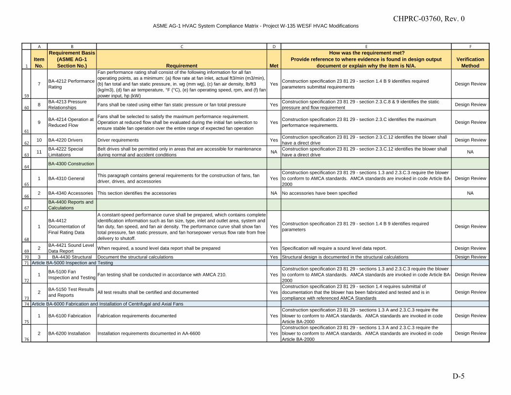
7 BA-4212 Performance Rating
Fan performance rating shall consist of the following information for all fan operating points, as a minimum: (a) flow rate at fan inlet, actual ft3/min (m3/min), (b) fan total and fan static pressure, in. wg (mm wg), (c) fan air density, lb/ft3 (kg/m3), (d) fan air temperature, °F (°C), (e) fan operating speed, rpm, and (f) fan power input, hp (kW)
Yes Construction specification 23 81 29 - section 1.4 B 9 identifies required parameters submittal requirements
Design Review
8 BA-4213 Pressure Relationships Fans shall be rated using either fan static pressure or fan total pressure Yes Construction specification 23 81 29 - section 2.3.C.8 & 9 identifies the static
pressure and flow requirement Design Review
9 BA-4214 Operation at Reduced Flow
Fans shall be selected to satisfy the maximum performance requirement. Operation at reduced flow shall be evaluated during the initial fan selection to ensure stable fan operation over the entire range of expected fan operation
Yes Construction specification 23 81 29 - section 2.3.C identifies the maximum performance requirements. Design Review
10 BA-4220 Drivers Driver requirements Yes Construction specification 23 81 29 - section 2.3.C.12 identifies the blower shall have a direct drive Design Review
11 BA-4222 Special Limitations
Belt drives shall be permitted only in areas that are accessible for maintenance during normal and accident conditions NA Construction specification 23 81 29 - section 2.3.C.12 identifies the blower shall
have a direct drive NA
BA-4300 Construction
1 BA-4310 General This paragraph contains general requirements for the construction of fans, fan driver, drives, and accessories Yes
Construction specification 23 81 29 - sections 1.3 and 2.3.C.3 require the blower to conform to AMCA standards. AMCA standards are invoked in code Article BA-2000
Design Review
2 BA-4340 Accessories This section identifies the accessories NA No accessories have been specified NA
BA-4400 Reports and Calculations
1BA-4412 Documentation of Final Rating Data
A constant-speed performance curve shall be prepared, which contains complete identification information such as fan size, type, inlet and outlet area, system and fan duty, fan speed, and fan air density. The performance curve shall show fan total pressure, fan static pressure, and fan horsepower versus flow rate from free delivery to shutoff.
Yes Construction specification 23 81 29 - section 1.4 B 9 identifies required parameters
Design Review
2 BA-4421 Sound Level Data Report When required, a sound level data report shall be prepared Yes Specification will require a sound level data report. Design Review
3 BA-4430 Structural Document the structural calculations Yes Structural design is documented in the structural calculations Design ReviewArticle BA-5000 Inspection and Testing
1 BA-5100 Fan Inspection and Testing Fan testing shall be conducted in accordance with AMCA 210. Yes
Construction specification 23 81 29 - sections 1.3 and 2.3.C.3 require the blower to conform to AMCA standards. AMCA standards are invoked in code Article BA-2000
Design Review
2 BA-5150 Test Results and Reports All test results shall be certified and documented Yes
Construction specification 23 81 29 - section 1.4 requires submittal of documentation that the blower has been fabricated and tested and is in compliance with referenced AMCA Standards
Design Review
Article BA-6000 Fabrication and Installation of Centrifugal and Axial Fans
1 BA-6100 Fabrication Fabrication requirements documented YesConstruction specification 23 81 29 - sections 1.3 A and 2.3.C.3 require the blower to conform to AMCA standards. AMCA standards are invoked in code Article BA-2000
Design Review
2 BA-6200 Installation Installation requirements documented in AA-6600 YesConstruction specification 23 81 29 - sections 1.3 A and 2.3.C.3 require the blower to conform to AMCA standards. AMCA standards are invoked in code Article BA-2000
Requirement Basis (ASME AG-1 Section No.) Requirement Met
How was the requirement met?Provide reference to where evidence is found in design output
document or explain why the item is N/A.Verification
Method77
78
79
80
81
82
83
84
85
86
87
88
89
90
91
92
93
94
95
96
97
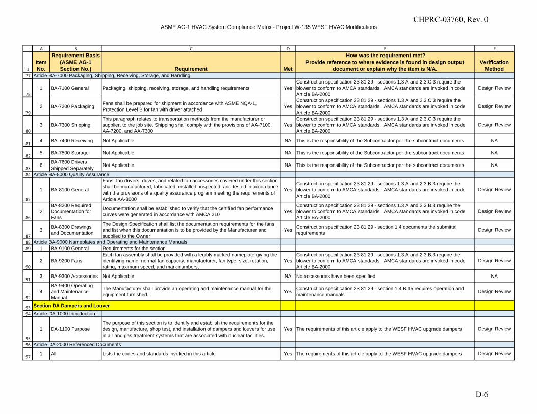
Article BA-7000 Packaging, Shipping, Receiving, Storage, and Handling
1 BA-7100 General Packaging, shipping, receiving, storage, and handling requirements YesConstruction specification 23 81 29 - sections 1.3 A and 2.3.C.3 require the blower to conform to AMCA standards. AMCA standards are invoked in code Article BA-2000
Design Review
2 BA-7200 Packaging Fans shall be prepared for shipment in accordance with ASME NQA-1, Protection Level B for fan with driver attached Yes
Construction specification 23 81 29 - sections 1.3 A and 2.3.C.3 require the blower to conform to AMCA standards. AMCA standards are invoked in code Article BA-2000
Design Review
3 BA-7300 ShippingThis paragraph relates to transportation methods from the manufacturer or supplier, to the job site. Shipping shall comply with the provisions of AA-7100, AA-7200, and AA-7300
YesConstruction specification 23 81 29 - sections 1.3 A and 2.3.C.3 require the blower to conform to AMCA standards. AMCA standards are invoked in code Article BA-2000
Design Review
4 BA-7400 Receiving Not Applicable NA This is the responsibility of the Subcontractor per the subcontract documents NA
5 BA-7500 Storage Not Applicable NA This is the responsibility of the Subcontractor per the subcontract documents NA
6 BA-7600 Drivers Shipped Separately Not Applicable NA This is the responsibility of the Subcontractor per the subcontract documents NA
Article BA-8000 Quality Assurance
1 BA-8100 General
Fans, fan drivers, drives, and related fan accessories covered under this section shall be manufactured, fabricated, installed, inspected, and tested in accordance with the provisions of a quality assurance program meeting the requirements of Article AA-8000
YesConstruction specification 23 81 29 - sections 1.3 A and 2.3.B.3 require the blower to conform to AMCA standards. AMCA standards are invoked in code Article BA-2000
Design Review
2BA-8200 Required Documentation for Fans
Documentation shall be established to verify that the certified fan performance curves were generated in accordance with AMCA 210 Yes
Construction specification 23 81 29 - sections 1.3 A and 2.3.B.3 require the blower to conform to AMCA standards. AMCA standards are invoked in code Article BA-2000
Design Review
3 BA-8300 Drawings and Documentation
The Design Specification shall list the documentation requirements for the fans and list when this documentation is to be provided by the Manufacturer and supplied to the Owner
Yes Construction specification 23 81 29 - section 1.4 documents the submittal requirements Design Review
Article BA-9000 Nameplates and Operating and Maintenance Manuals 1 BA-9100 General Requirements for the section
2 BA-9200 Fans Each fan assembly shall be provided with a legibly marked nameplate giving the identifying name, normal fan capacity, manufacturer, fan type, size, rotation, rating, maximum speed, and mark numbers,
YesConstruction specification 23 81 29 - sections 1.3 A and 2.3.B.3 require the blower to conform to AMCA standards. AMCA standards are invoked in code Article BA-2000
Design Review
3 BA-9300 Accessories Not Applicable NA No accessories have been specified NA
4BA-9400 Operating and Maintenance Manual
The Manufacturer shall provide an operating and maintenance manual for the equipment furnished. Yes Construction specification 23 81 29 - section 1.4.B.15 requires operation and
maintenance manuals Design Review
Section DA Dampers and LouverArticle DA-1000 Introduction
1 DA-1100 PurposeThe purpose of this section is to identify and establish the requirements for the design, manufacture, shop test, and installation of dampers and louvers for use in air and gas treatment systems that are associated with nuclear facilities.
Yes The requirements of this article apply to the WESF HVAC upgrade dampers Design Review
Article DA-2000 Referenced Documents
1 All Lists the codes and standards invoked in this article Yes The requirements of this article apply to the WESF HVAC upgrade dampers Design Review
Requirement Basis (ASME AG-1 Section No.) Requirement Met
How was the requirement met?Provide reference to where evidence is found in design output
document or explain why the item is N/A.Verification
Method98
99
100
101
102
103
104
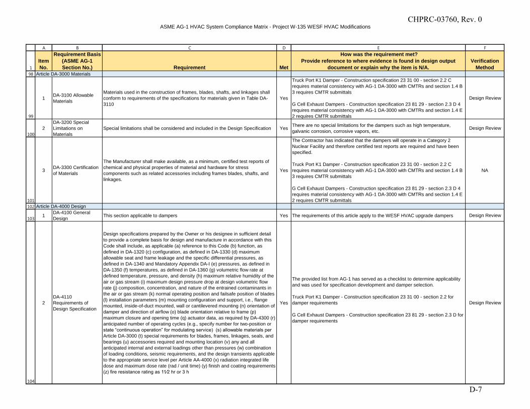
Article DA-3000 Materials
1 DA-3100 Allowable Materials
Materials used in the construction of frames, blades, shafts, and linkages shall conform to requirements of the specifications for materials given in Table DA-3110
Yes
Truck Port K1 Damper - Construction specification 23 31 00 - section 2.2 C requires material consistency with AG-1 DA-3000 with CMTRs and section 1.4 B 3 requires CMTR submittals
G Cell Exhaust Dampers - Construction specification 23 81 29 - section 2.3 D 4 requires material consistency with AG-1 DA-3000 with CMTRs and section 1.4 E 2 requires CMTR submittals
Design Review
2DA-3200 Special Limitations on Materials
Special limitations shall be considered and included in the Design Specification Yes There are no special limitations for the dampers such as high temperature, galvanic corrosion, corrosive vapors, etc. Design Review
3 DA-3300 Certification of Materials
The Manufacturer shall make available, as a minimum, certified test reports of chemical and physical properties of material and hardware for stress components such as related accessories including frames blades, shafts, and linkages.
Yes
The Contractor has indicated that the dampers will operate in a Category 2 Nuclear Facility and therefore certified test reports are required and have been specified.
Truck Port K1 Damper - Construction specification 23 31 00 - section 2.2 C requires material consistency with AG-1 DA-3000 with CMTRs and section 1.4 B 3 requires CMTR submittals
G Cell Exhaust Dampers - Construction specification 23 81 29 - section 2.3 D 4 requires material consistency with AG-1 DA-3000 with CMTRs and section 1.4 E 2 requires CMTR submittals
NA
Article DA-4000 Design
1 DA-4100 General Design This section applicable to dampers Yes The requirements of this article apply to the WESF HVAC upgrade dampers Design Review
2DA-4110 Requirements of Design Specification
Design specifications prepared by the Owner or his designee in sufficient detail to provide a complete basis for design and manufacture in accordance with this Code shall include, as applicable (a) reference to this Code (b) function, as defined in DA-1320 (c) configuration, as defined in DA-1330 (d) maximum allowable seat and frame leakage and the specific differential pressures, as defined in DA-1340 and Mandatory Appendix DA-I (e) pressures, as defined in DA-1350 (f) temperatures, as defined in DA-1360 (g) volumetric flow rate at defined temperature, pressure, and density (h) maximum relative humidity of the air or gas stream (i) maximum design pressure drop at design volumetric flow rate (j) composition, concentration, and nature of the entrained contaminants in the air or gas stream (k) normal operating position and failsafe position of blades (l) installation parameters (m) mounting configuration and support, i.e., flange mounted, inside-of-duct mounted, wall or cantilevered mounting (n) orientation of damper and direction of airflow (o) blade orientation relative to frame (p) maximum closure and opening time (q) actuator data, as required by DA-4300 (r) anticipated number of operating cycles (e.g., specify number for two-position or state “continuous operation” for modulating service) (s) allowable materials per
Article DA-3000 (t) special requirements for blades, frames, linkages, seals, and bearings (u) accessories required and mounting location (v) any and all anticipated internal and external loadings other than pressures (w) combination of loading conditions, seismic requirements, and the design transients applicable to the appropriate service level per Article AA-4000 (x) radiation integrated life dose and maximum dose rate (rad / unit time) (y) finish and coating requirements (z) fire resistance rating as 11⁄2 hr or 3 h
Yes
The provided list from AG-1 has served as a checklist to determine applicability and was used for specification development and damper selection.
Truck Port K1 Damper - Construction specification 23 31 00 - section 2.2 for damper requirements G Cell Exhaust Dampers - Construction specification 23 81 29 - section 2.3 D for damper requirements
Requirement Basis (ASME AG-1 Section No.) Requirement Met
How was the requirement met?Provide reference to where evidence is found in design output
document or explain why the item is N/A.Verification
Method
105
106
107
108
109
110
111
112
113
114
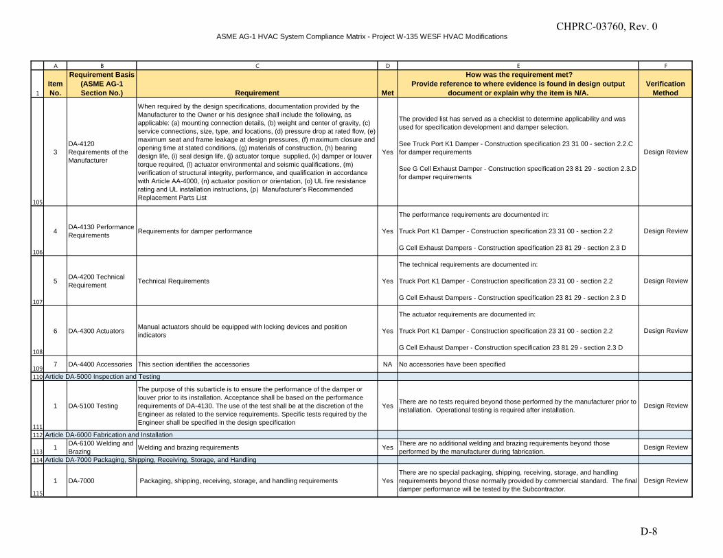
115
3DA-4120 Requirements of the Manufacturer
When required by the design specifications, documentation provided by the Manufacturer to the Owner or his designee shall include the following, as applicable: (a) mounting connection details, (b) weight and center of gravity, (c) service connections, size, type, and locations, (d) pressure drop at rated flow, (e) maximum seat and frame leakage at design pressures, (f) maximum closure and opening time at stated conditions, (g) materials of construction, (h) bearing design life, (i) seal design life, (j) actuator torque supplied, (k) damper or louver torque required, (l) actuator environmental and seismic qualifications, (m) verification of structural integrity, performance, and qualification in accordance with Article AA-4000, (n) actuator position or orientation, (o) UL fire resistance rating and UL installation instructions, (p) Manufacturer’s Recommended
Replacement Parts List
Yes
The provided list has served as a checklist to determine applicability and was used for specification development and damper selection.
See Truck Port K1 Damper - Construction specification 23 31 00 - section 2.2.C for damper requirements
See G Cell Exhaust Damper - Construction specification 23 81 29 - section 2.3.D for damper requirements
Design Review
4 DA-4130 Performance Requirements Requirements for damper performance Yes
The performance requirements are documented in:
Truck Port K1 Damper - Construction specification 23 31 00 - section 2.2
G Cell Exhaust Dampers - Construction specification 23 81 29 - section 2.3 D
Truck Port K1 Damper - Construction specification 23 31 00 - section 2.2
G Cell Exhaust Dampers - Construction specification 23 81 29 - section 2.3 D
Design Review
6 DA-4300 Actuators Manual actuators should be equipped with locking devices and position indicators Yes
The actuator requirements are documented in:
Truck Port K1 Damper - Construction specification 23 31 00 - section 2.2 G Cell Exhaust Damper - Construction specification 23 81 29 - section 2.3 D
Design Review
7 DA-4400 Accessories This section identifies the accessories NA No accessories have been specified
Article DA-5000 Inspection and Testing
1 DA-5100 Testing
The purpose of this subarticle is to ensure the performance of the damper or louver prior to its installation. Acceptance shall be based on the performance requirements of DA-4130. The use of the test shall be at the discretion of the Engineer as related to the service requirements. Specific tests required by the Engineer shall be specified in the design specification
Yes There are no tests required beyond those performed by the manufacturer prior to installation. Operational testing is required after installation. Design Review
Article DA-6000 Fabrication and Installation
1 DA-6100 Welding and Brazing Welding and brazing requirements Yes There are no additional welding and brazing requirements beyond those
performed by the manufacturer during fabrication. Design Review
Article DA-7000 Packaging, Shipping, Receiving, Storage, and Handling
1 DA-7000 Packaging, shipping, receiving, storage, and handling requirements YesThere are no special packaging, shipping, receiving, storage, and handling requirements beyond those normally provided by commercial standard. The final damper performance will be tested by the Subcontractor.
Requirement Basis (ASME AG-1 Section No.) Requirement Met
How was the requirement met?Provide reference to where evidence is found in design output
document or explain why the item is N/A.Verification
Method116
117
118
119
120
121
122
123
124
125
126
127
128
129
Article DA-8000 Quality Assurance
1 DA-8100 Damper and Louver Performance
Documentation shall be established to verify that damper and louver performance complies with the testing criteria Yes
Truck Port K1 Damper - Construction specification 23 31 00 - section 3.2 B 1 documents requirement to perform operational testing requirements
G Cell Exhaust Damper - Construction specification 23 81 29 - section 3.4 documents requirement to perform operational testing requirements
Design Review
2 DA-8200 Apparently removed from the code - not included NA NA
3 DA-8300 Quality Assurance Records
Documentation shall be prepared, maintained, and submitted to the Owner for record Yes
Truck Port K1 Damper - Construction specification 23 31 00 - section 1.4 documents submittals
G Cell Exhaust Dampers - Construction specification 23 81 29 - section 1.4 documents submittals
Design Review
Article DA-9000 Nameplates and Operating and Maintenance Manuals
1 DA-9100 Nameplates and Stampings Requirements for nameplates Yes
Truck Port K1 Damper - Construction specification 23 31 00 - section 2.2 F requires nameplates
G Cell Exhaust Damper - Construction specification 23 81 29 - section 2.1 C requires nameplates
Design Review
2 DA-9200 ManualsThe Manufacturer shall provide a manual or manuals for the equipment furnished. The manual shall include a recommended spare parts list and recommended installation, maintenance, and operational procedures.
Yes
Truck Port K1 Damper - Construction specification 23 31 00 - section 1.4 C 1 requires damper catalog information
G Cell Exhaust Damper - Construction specification 23 81 29 - section 1.4 B 15 requires O&M Manuals
Design Review
Section SA Ductwork
1 THROUGHOUTAG-1 throughout the code references that duct design and fabrication to SMACNA standards is acceptable. See sections AA-D-1000, AA-D-2400, AA-D-3200, AA-D-3520, SA-5410, SA-C-1100, SA-C-1300, HA-B-1000
Yes The K1 rerouted ducting has been designed to meet SMACNA requirements. See the SMACNA compliance matrix below. Design Review
Article SA-C-1000 Additional Guidelines for duct design and construction
1SA-C-1300 Duct Construction Standards
Table SA-C-1300 lists standards that may be used in the mechanical design of ductwork. The SMACNA HVAC Duct Construction Standards contain design data for both indicated in the Table.
When using either the Round or Rectangular Industrial Duct Construction Standards for nuclear power plant system design, the system may be considered as “Class 1,” as defined by SMACNA.
Yes
Per the allowance to use SMACNA standards in AG-1 the Truck Port K1 duct reroute has been designed per SMACNA standards.
See SMACNA compliance matrix below.
Design Review
2 Table SA-C-1300 Yes Table included in AG-1 documenting SMACNA acceptability Design Review
Article SA-1000 Scope
1 All Lists the codes and standards invoked in this article Yes Compliance SMACNA standards - See SMACNA compliance matrix below Design Review
Requirement Basis (ASME AG-1 Section No.) Requirement Met
How was the requirement met?Provide reference to where evidence is found in design output
document or explain why the item is N/A.Verification
Method130
131
132
133
134
135
136
137
138
139
140
141
142
143
144
145
146
147
148
149
150
151
152
153
154
155
156
157
158
159
160
161
162
163
164
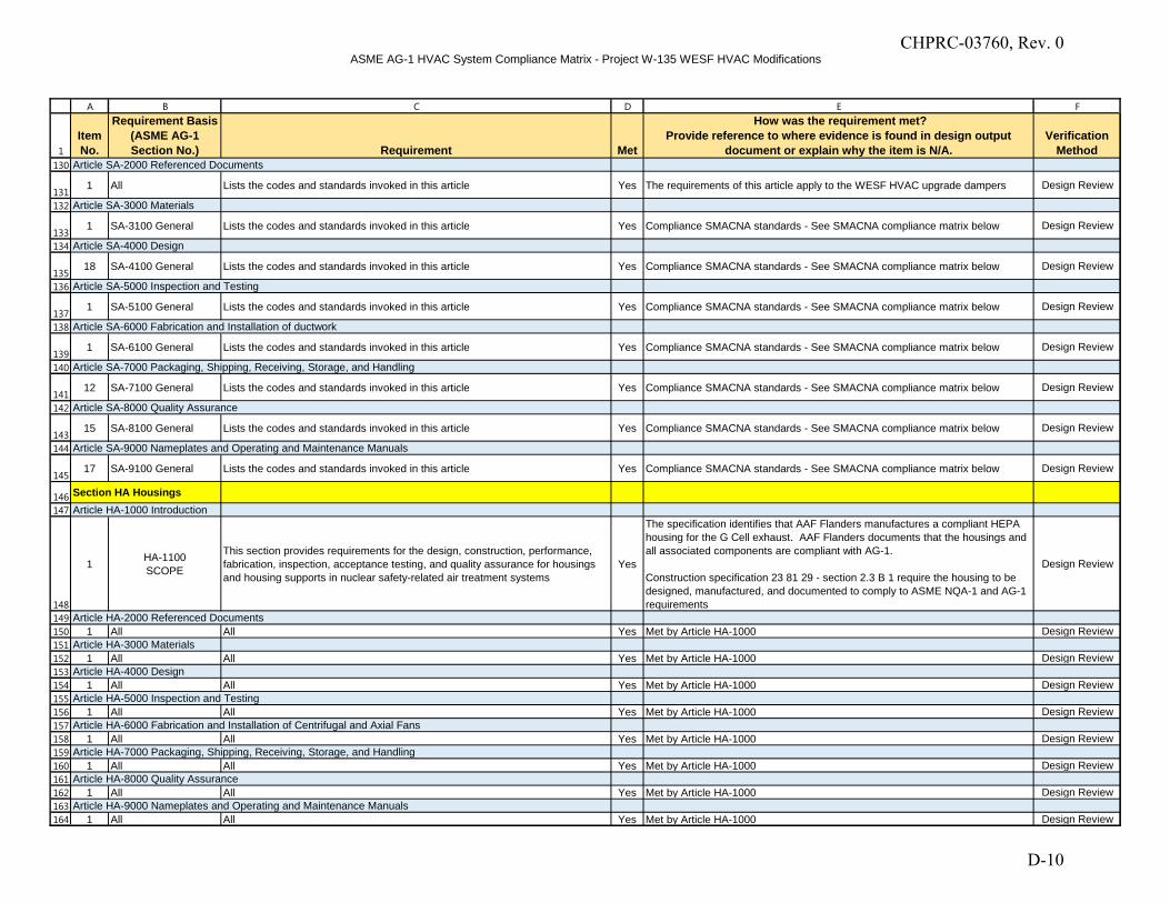
Article SA-2000 Referenced Documents
1 All Lists the codes and standards invoked in this article Yes The requirements of this article apply to the WESF HVAC upgrade dampers Design Review
Article SA-3000 Materials
1 SA-3100 General Lists the codes and standards invoked in this article Yes Compliance SMACNA standards - See SMACNA compliance matrix below Design Review
Article SA-4000 Design
18 SA-4100 General Lists the codes and standards invoked in this article Yes Compliance SMACNA standards - See SMACNA compliance matrix below Design Review
Article SA-5000 Inspection and Testing
1 SA-5100 General Lists the codes and standards invoked in this article Yes Compliance SMACNA standards - See SMACNA compliance matrix below Design Review
Article SA-6000 Fabrication and Installation of ductwork
1 SA-6100 General Lists the codes and standards invoked in this article Yes Compliance SMACNA standards - See SMACNA compliance matrix below Design Review
Article SA-7000 Packaging, Shipping, Receiving, Storage, and Handling
12 SA-7100 General Lists the codes and standards invoked in this article Yes Compliance SMACNA standards - See SMACNA compliance matrix below Design Review
Article SA-8000 Quality Assurance
15 SA-8100 General Lists the codes and standards invoked in this article Yes Compliance SMACNA standards - See SMACNA compliance matrix below Design Review
Article SA-9000 Nameplates and Operating and Maintenance Manuals
17 SA-9100 General Lists the codes and standards invoked in this article Yes Compliance SMACNA standards - See SMACNA compliance matrix below Design Review
Section HA HousingsArticle HA-1000 Introduction
1 HA-1100SCOPE
This section provides requirements for the design, construction, performance, fabrication, inspection, acceptance testing, and quality assurance for housings and housing supports in nuclear safety-related air treatment systems
Yes
The specification identifies that AAF Flanders manufactures a compliant HEPA housing for the G Cell exhaust. AAF Flanders documents that the housings and all associated components are compliant with AG-1.
Construction specification 23 81 29 - section 2.3 B 1 require the housing to be designed, manufactured, and documented to comply to ASME NQA-1 and AG-1 requirements
Design Review
Article HA-2000 Referenced Documents1 All All Yes Met by Article HA-1000 Design Review
Article HA-3000 Materials1 All All Yes Met by Article HA-1000 Design Review
Article HA-4000 Design1 All All Yes Met by Article HA-1000 Design Review
Article HA-5000 Inspection and Testing1 All All Yes Met by Article HA-1000 Design Review
Article HA-6000 Fabrication and Installation of Centrifugal and Axial Fans1 All All Yes Met by Article HA-1000 Design Review
Article HA-7000 Packaging, Shipping, Receiving, Storage, and Handling1 All All Yes Met by Article HA-1000 Design Review
Article HA-8000 Quality Assurance1 All All Yes Met by Article HA-1000 Design Review
Article HA-9000 Nameplates and Operating and Maintenance Manuals 1 All All Yes Met by Article HA-1000 Design Review
Requirement Basis (ASME AG-1 Section No.) Requirement Met
How was the requirement met?Provide reference to where evidence is found in design output
document or explain why the item is N/A.Verification
Method
165
166
167
168
169
170
171
172
173
174
175
176
177
178
179
180
181
182
183
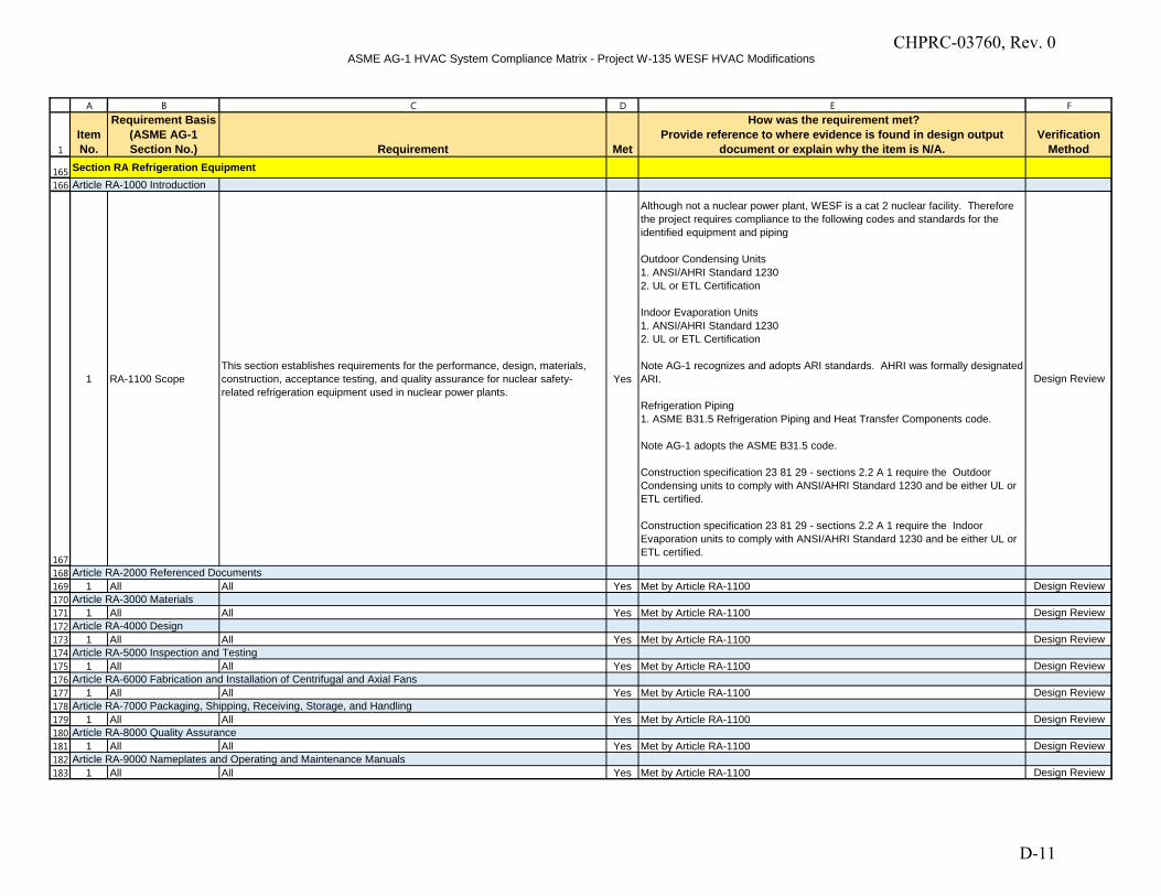
Section RA Refrigeration Equipment Article RA-1000 Introduction
1 RA-1100 ScopeThis section establishes requirements for the performance, design, materials, construction, acceptance testing, and quality assurance for nuclear safety-related refrigeration equipment used in nuclear power plants.
Yes
Although not a nuclear power plant, WESF is a cat 2 nuclear facility. Therefore the project requires compliance to the following codes and standards for the identified equipment and piping
Outdoor Condensing Units1. ANSI/AHRI Standard 12302. UL or ETL Certification
Indoor Evaporation Units1. ANSI/AHRI Standard 12302. UL or ETL Certification
Note AG-1 recognizes and adopts ARI standards. AHRI was formally designated ARI.
Refrigeration Piping1. ASME B31.5 Refrigeration Piping and Heat Transfer Components code.
Note AG-1 adopts the ASME B31.5 code.
Construction specification 23 81 29 - sections 2.2 A 1 require the Outdoor Condensing units to comply with ANSI/AHRI Standard 1230 and be either UL or ETL certified.
Construction specification 23 81 29 - sections 2.2 A 1 require the Indoor Evaporation units to comply with ANSI/AHRI Standard 1230 and be either UL or ETL certified.
Design Review
Article RA-2000 Referenced Documents1 All All Yes Met by Article RA-1100 Design Review
Article RA-3000 Materials1 All All Yes Met by Article RA-1100 Design Review
Article RA-4000 Design1 All All Yes Met by Article RA-1100 Design Review
Article RA-5000 Inspection and Testing1 All All Yes Met by Article RA-1100 Design Review
Article RA-6000 Fabrication and Installation of Centrifugal and Axial Fans1 All All Yes Met by Article RA-1100 Design Review
Article RA-7000 Packaging, Shipping, Receiving, Storage, and Handling1 All All Yes Met by Article RA-1100 Design Review
Article RA-8000 Quality Assurance1 All All Yes Met by Article RA-1100 Design Review
Article RA-9000 Nameplates and Operating and Maintenance Manuals 1 All All Yes Met by Article RA-1100 Design Review
Requirement Basis (ASME AG-1 Section No.) Requirement Met
How was the requirement met?Provide reference to where evidence is found in design output
document or explain why the item is N/A.Verification
Method
184
185
186
187
188
189
190
191
192
193
194
195
196
197
198
199
200
201
Section CA Conditioning Equipment.Article CA-1000 Introduction
1 CA-1100 Scope
This section establishes requirements for the design, manufacture, testing, and documentation for forced circulation air cooling and heating coils, air washers, evaporative coolers, and electric heating coils used in nuclear safety-related (AA-1130) air conditioning and air and gas treatment systems in nuclear facilities
NA The WESF space cooling system is specifically not applicable to this Article per the exclusion statement NA
2 CA-1132 Exclusion of Components
Conditioning equipment and associated accessories not included in this section are humidifiers, dehumidifiers of the adsorption type, infrared heating devices, controllers, valves, strainers, traps, pumps, refrigerant expansion valves, shell- and tube-type refrigerant evaporators and condensers, and compressors
NA The WESF space cooling system is specifically not applicable to this Article per the exclusion statement NA
Section FA Moisture Separators
1 FA-1121 Moisture Separators
This section applies to modular, impingement-type liquid droplet separators in liquid water entrained air streams, which typically employ layers of fibers, layers of mesh, or alternating layers of each
NA This Article is not applicable. There are no moisture separators in this design. NA
Section FB Medium Efficiency Filters
1 FB-1100 ScopeThis section of the Code provides minimum requirements for the performance, design, construction, acceptance testing, and quality assurance for medium efficiency filters used in air and gas treatment systems in nuclear facilities
YesThe opportunity to use pre-filters is included in the G Cell exhaust filter housing. However the CHPRC will provide the actual filters. See specification 23 81 29 - section 2.3 B 5
NA
Section FC HEPA Filters
1 FC-1100 ScopeThis section provides requirements for the performance, design, construction, acceptance testing, and quality assurance for high efficiency particulate air (HEPA) filters used in nuclear air or gas treatment systems
YesThe opportunity to use HEPA filters is included in the G Cell exhaust filter housing. However the CHPRC will provide the actual filters. See specification 23 81 29 - section 2.3 B 6
NA
Section FD Type II Adsorber Cells
1 FD-1100 ScopeThis section of the Code provides minimum requirements for the performance, design, construction, acceptance testing, and quality assurance for modular gas phase adsorber cells used in nuclear safety-related air or gas treatment systems
NA This Article is not applicable. There are no absorber cells in this design. NA
Section FE Type III Adsorbers
1 FE-1100 ScopeThis section of the Code provides minimum requirements for the performance, design, testing, construction, and quality assurance of gas phase adsorber units used in nuclear safety-related air or gas treatment systems.
NA This Article is not applicable. There are no absorber units in this design. NA
Section FF Adsorbent Media
1 FF-1100 ScopeThis section provides minimum requirements for the performance, design, acceptance testing, and quality assurance for adsorbent media used in air and gas cleaning systems in nuclear facilities
NA This Article is not applicable. There is no absorbent media in this design. NA
This section of the Code provides the requirements for the design, fabrication, inspection, acceptance testing, and quality assurance of mounting frames for medium efficiency filters, moisture separators, as well as high efficiency particulate air (HEPA) filters and Type II (tray type) adsorber cells used in nuclear safety related air and gas treatment systems
NA This Article is not applicable. There is no filter frames in this design NA
Requirement Basis (ASME AG-1 Section No.) Requirement Met
How was the requirement met?Provide reference to where evidence is found in design output
document or explain why the item is N/A.Verification
Method
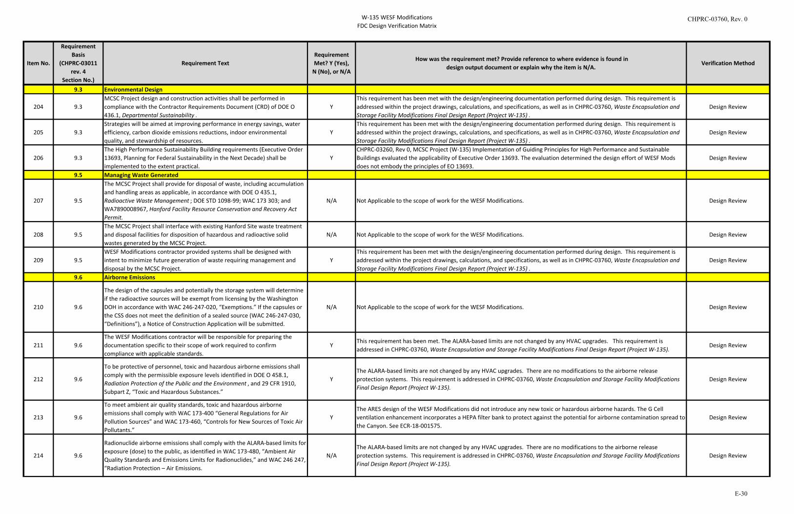
202
203
204
205
206
207
208
209
210
211
212
213
214
215
216
217
218
219
220
221
222
223
224
225
226
227
228
229
230
231232
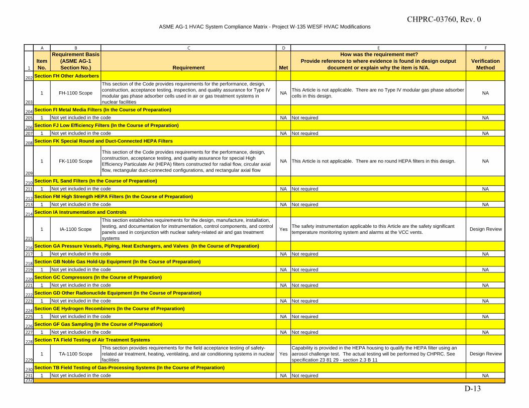
Section FH Other Adsorbers
1 FH-1100 Scope
This section of the Code provides requirements for the performance, design, construction, acceptance testing, inspection, and quality assurance for Type IV modular gas phase adsorber cells used in air or gas treatment systems in nuclear facilities
NA This Article is not applicable. There are no Type IV modular gas phase adsorber cells in this design. NA
Section FI Metal Media Filters (In the Course of Preparation)1 Not yet included in the code NA Not required NA
Section FJ Low Efficiency Filters (In the Course of Preparation)1 Not yet included in the code NA Not required NA
Section FK Special Round and Duct-Connected HEPA Filters
1 FK-1100 Scope
This section of the Code provides requirements for the performance, design, construction, acceptance testing, and quality assurance for special High Efficiency Particulate Air (HEPA) filters constructed for radial flow, circular axial flow, rectangular duct-connected configurations, and rectangular axial flow
NA This Article is not applicable. There are no round HEPA filters in this design. NA
Section FL Sand Filters (In the Course of Preparation)1 Not yet included in the code NA Not required NA
Section FM High Strength HEPA Filters (In the Course of Preparation)1 Not yet included in the code NA Not required NA
Section IA Instrumentation and Controls
1 IA-1100 Scope
This section establishes requirements for the design, manufacture, installation, testing, and documentation for instrumentation, control components, and control panels used in conjunction with nuclear safety-related air and gas treatment systems
Yes The safety instrumentation applicable to this Article are the safety significant temperature monitoring system and alarms at the VCC vents. Design Review
Section GA Pressure Vessels, Piping, Heat Exchangers, and Valves (In the Course of Preparation)1 Not yet included in the code NA Not required NA
Section GB Noble Gas Hold-Up Equipment (In the Course of Preparation)1 Not yet included in the code NA Not required NA
Section GC Compressors (In the Course of Preparation)1 Not yet included in the code NA Not required NA
Section GD Other Radionuclide Equipment (In the Course of Preparation)1 Not yet included in the code NA Not required NA
Section GE Hydrogen Recombiners (In the Course of Preparation)1 Not yet included in the code NA Not required NA
Section GF Gas Sampling (In the Course of Preparation)1 Not yet included in the code NA Not required NA
Section TA Field Testing of Air Treatment Systems
1 TA-1100 ScopeThis section provides requirements for the field acceptance testing of safety-related air treatment, heating, ventilating, and air conditioning systems in nuclear facilities
YesCapability is provided in the HEPA housing to qualify the HEPA filter using an aerosol challenge test. The actual testing will be performed by CHPRC. See specification 23 81 29 - section 2.3 B 11
Design Review
Section TB Field Testing of Gas-Processing Systems (In the Course of Preparation)1 Not yet included in the code NA Not required NA
Requirement Basis (ASME AG-1 Section No.) Requirement Met
How was the requirement met?Provide reference to where evidence is found in design output
document or explain why the item is N/A.Verification
Method233
234
235
236
237
238
239
240
241
242
243
244
245
246
247
248
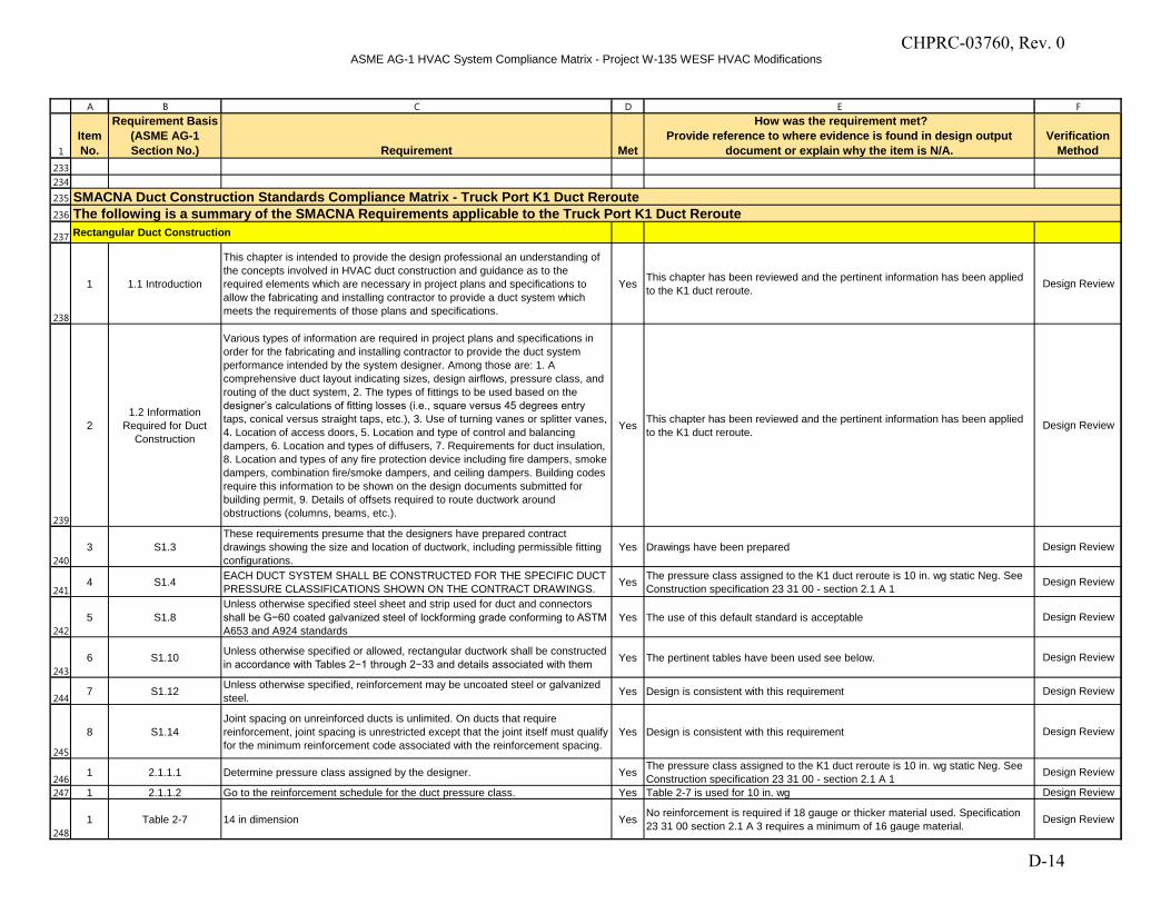
Rectangular Duct Construction
1 1.1 Introduction
This chapter is intended to provide the design professional an understanding of the concepts involved in HVAC duct construction and guidance as to the required elements which are necessary in project plans and specifications to allow the fabricating and installing contractor to provide a duct system which meets the requirements of those plans and specifications.
Yes This chapter has been reviewed and the pertinent information has been applied to the K1 duct reroute. Design Review
21.2 Information
Required for Duct Construction
Various types of information are required in project plans and specifications in order for the fabricating and installing contractor to provide the duct system performance intended by the system designer. Among those are: 1. A comprehensive duct layout indicating sizes, design airflows, pressure class, and routing of the duct system, 2. The types of fittings to be used based on the designer’s calculations of fitting losses (i.e., square versus 45 degrees entry
taps, conical versus straight taps, etc.), 3. Use of turning vanes or splitter vanes, 4. Location of access doors, 5. Location and type of control and balancing dampers, 6. Location and types of diffusers, 7. Requirements for duct insulation, 8. Location and types of any fire protection device including fire dampers, smoke dampers, combination fire/smoke dampers, and ceiling dampers. Building codes require this information to be shown on the design documents submitted for building permit, 9. Details of offsets required to route ductwork around obstructions (columns, beams, etc.).
Yes This chapter has been reviewed and the pertinent information has been applied to the K1 duct reroute.
Design Review
3 S1.3These requirements presume that the designers have prepared contract drawings showing the size and location of ductwork, including permissible fitting configurations.
Yes Drawings have been prepared Design Review
4 S1.4 EACH DUCT SYSTEM SHALL BE CONSTRUCTED FOR THE SPECIFIC DUCT PRESSURE CLASSIFICATIONS SHOWN ON THE CONTRACT DRAWINGS. Yes The pressure class assigned to the K1 duct reroute is 10 in. wg static Neg. See
Construction specification 23 31 00 - section 2.1 A 1Design Review
5 S1.8Unless otherwise specified steel sheet and strip used for duct and connectors shall be G−60 coated galvanized steel of lockforming grade conforming to ASTM
A653 and A924 standardsYes The use of this default standard is acceptable Design Review
6 S1.10 Unless otherwise specified or allowed, rectangular ductwork shall be constructed in accordance with Tables 2−1 through 2−33 and details associated with them
Yes The pertinent tables have been used see below. Design Review
7 S1.12 Unless otherwise specified, reinforcement may be uncoated steel or galvanized steel. Yes Design is consistent with this requirement Design Review
8 S1.14Joint spacing on unreinforced ducts is unlimited. On ducts that require reinforcement, joint spacing is unrestricted except that the joint itself must qualify for the minimum reinforcement code associated with the reinforcement spacing.
Yes Design is consistent with this requirement Design Review
1 2.1.1.1 Determine pressure class assigned by the designer. Yes The pressure class assigned to the K1 duct reroute is 10 in. wg static Neg. See Construction specification 23 31 00 - section 2.1 A 1 Design Review
1 2.1.1.2 Go to the reinforcement schedule for the duct pressure class. Yes Table 2-7 is used for 10 in. wg Design Review
1 Table 2-7 14 in dimension Yes No reinforcement is required if 18 gauge or thicker material used. Specification 23 31 00 section 2.1 A 3 requires a minimum of 16 gauge material. Design Review
SMACNA Duct Construction Standards Compliance Matrix - Truck Port K1 Duct RerouteThe following is a summary of the SMACNA Requirements applicable to the Truck Port K1 Duct Reroute
Requirement Basis (ASME AG-1 Section No.) Requirement Met
How was the requirement met?Provide reference to where evidence is found in design output
document or explain why the item is N/A.Verification
Method
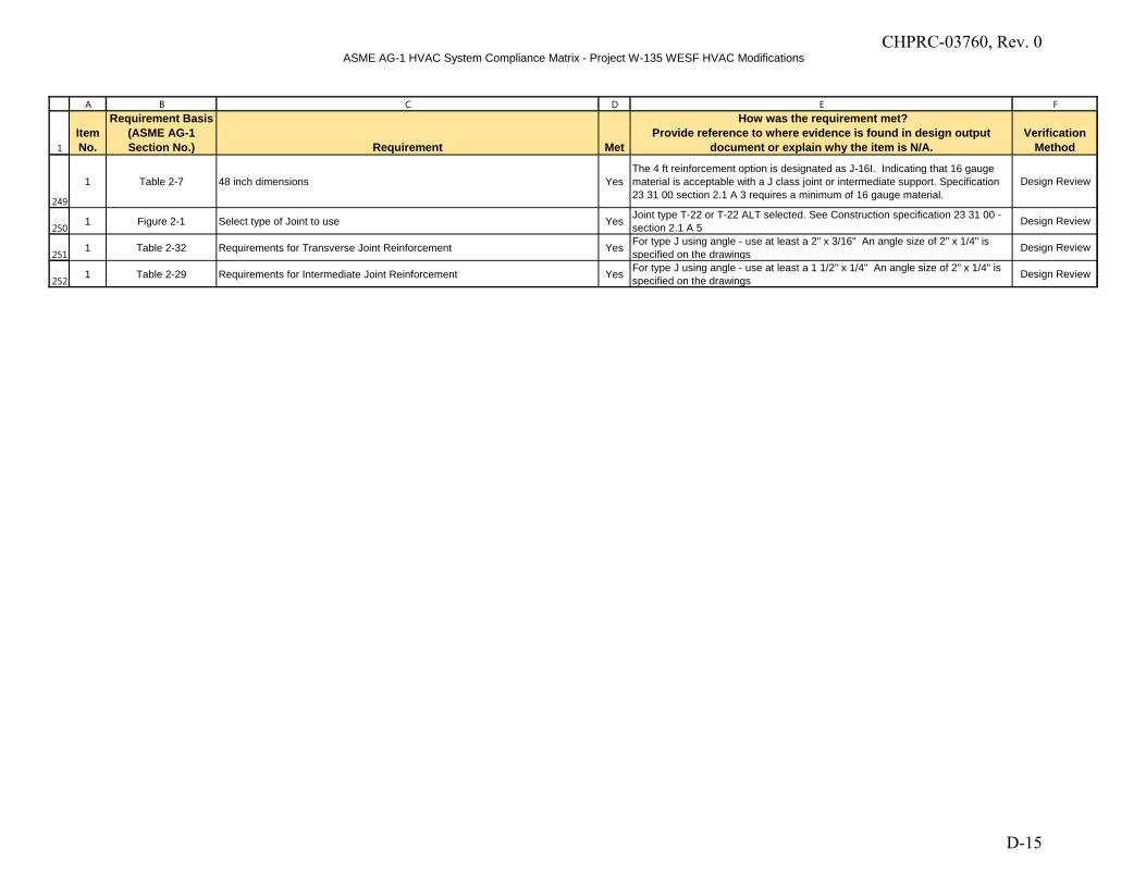
249
250
251
252
1 Table 2-7 48 inch dimensions YesThe 4 ft reinforcement option is designated as J-16I. Indicating that 16 gauge material is acceptable with a J class joint or intermediate support. Specification 23 31 00 section 2.1 A 3 requires a minimum of 16 gauge material.
Design Review
1 Figure 2-1 Select type of Joint to use Yes Joint type T-22 or T-22 ALT selected. See Construction specification 23 31 00 - section 2.1 A 5 Design Review
1 Table 2-32 Requirements for Transverse Joint Reinforcement Yes For type J using angle - use at least a 2" x 3/16" An angle size of 2" x 1/4" is specified on the drawings Design Review
1 Table 2-29 Requirements for Intermediate Joint Reinforcement Yes For type J using angle - use at least a 1 1/2" x 1/4" An angle size of 2" x 1/4" is specified on the drawings Design Review
How was the requirement met? Provide reference to where evidence is found indesign output document or explain why the item is N/A.
Verification Method
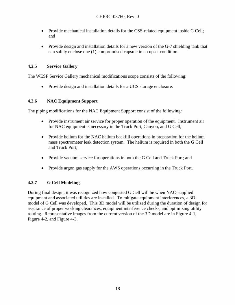
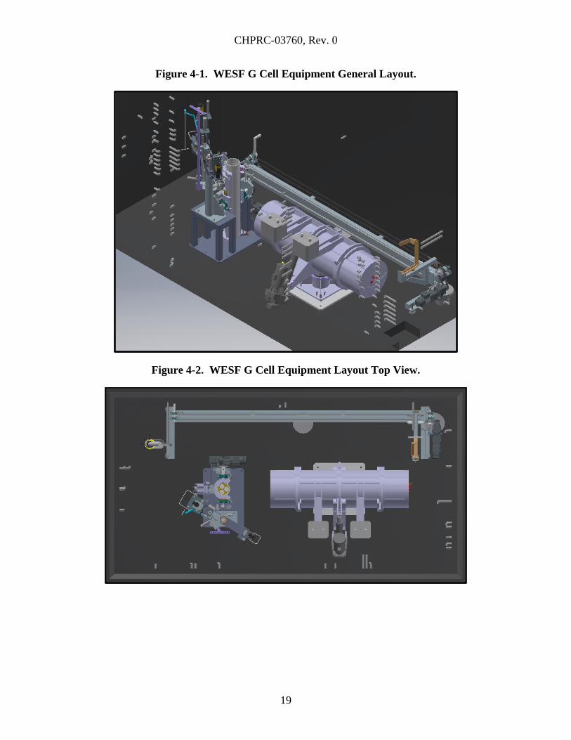
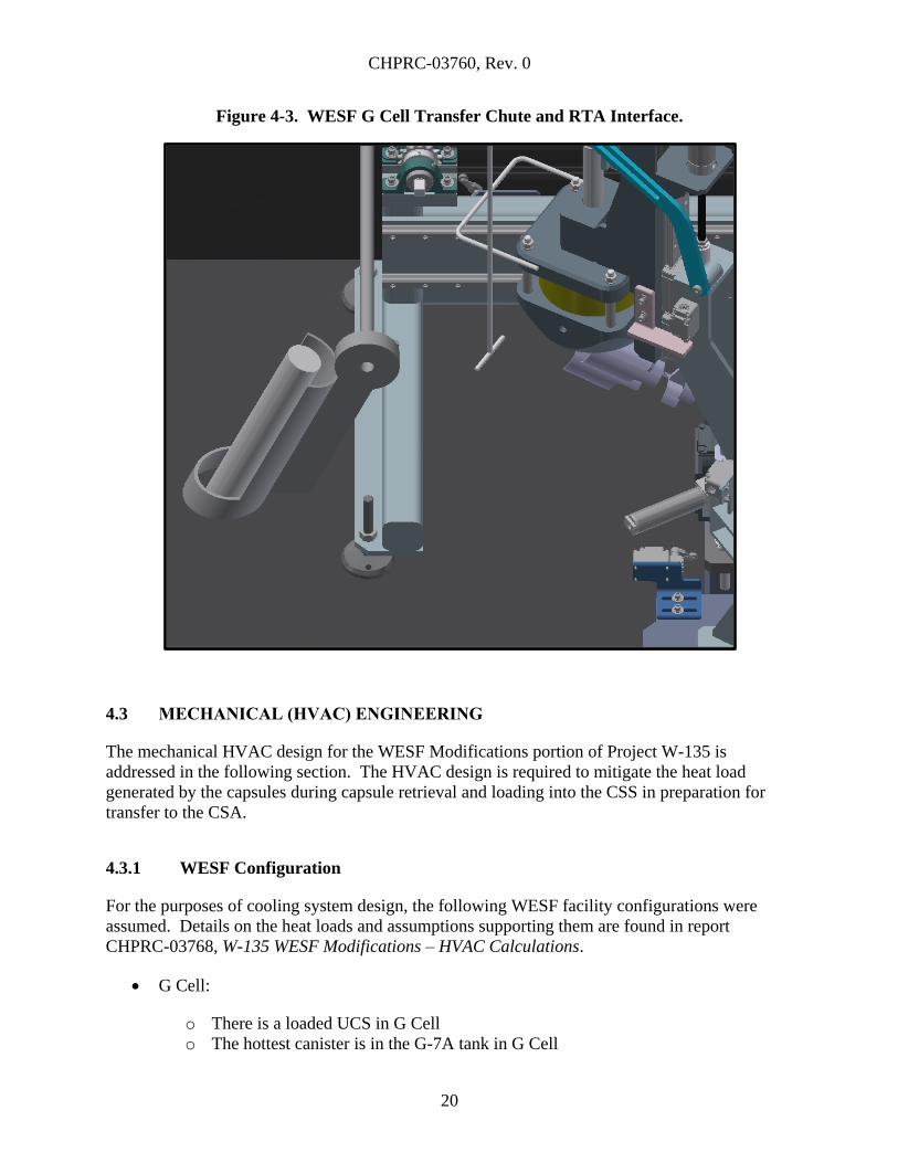
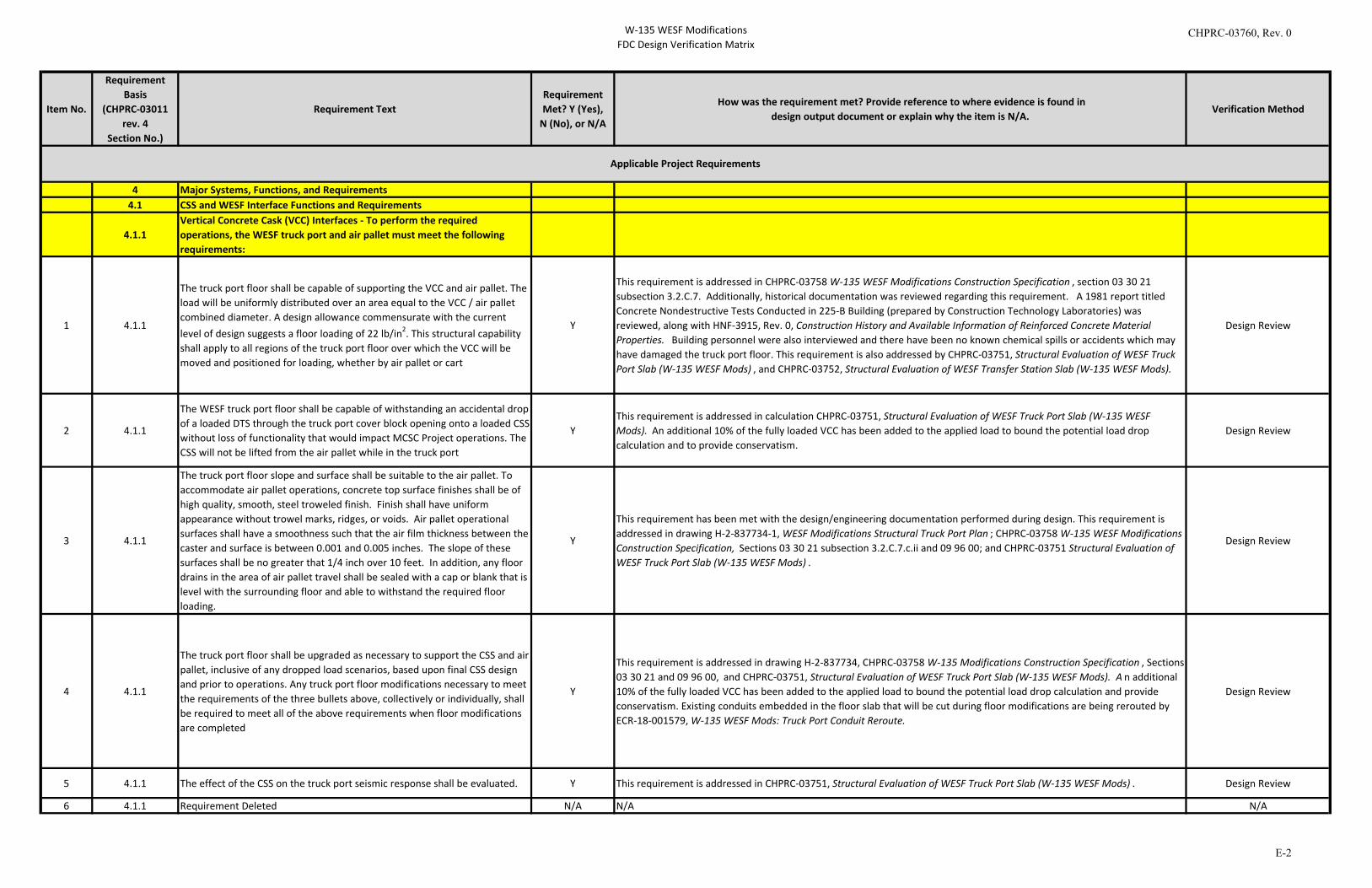
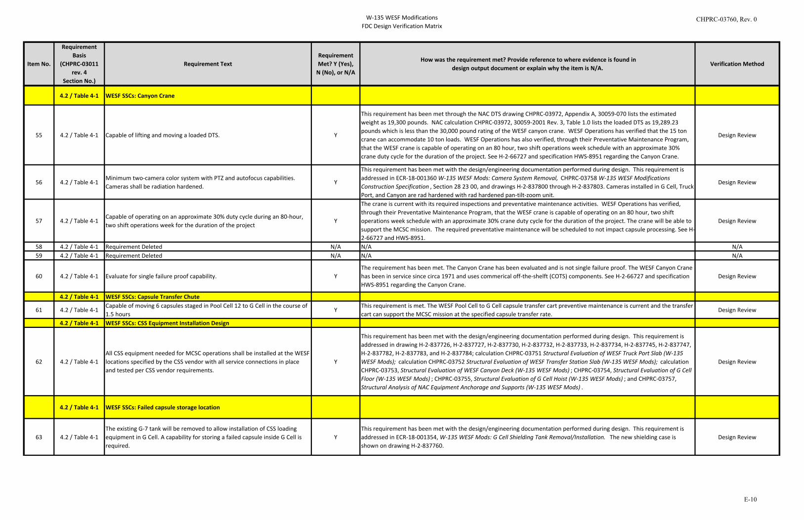
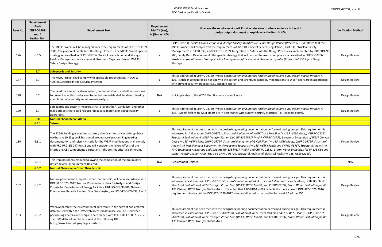
4 Major Systems, Functions, and Requirements4.1 CSS and WESF Interface Functions and Requirements
4.1.1Vertical Concrete Cask (VCC) Interfaces - To perform the required operations, the WESF truck port and air pallet must meet the following requirements:
1 4.1.1
The truck port floor shall be capable of supporting the VCC and air pallet. The load will be uniformly distributed over an area equal to the VCC / air pallet combined diameter. A design allowance commensurate with the current level of design suggests a floor loading of 22 lb/in2. This structural capability shall apply to all regions of the truck port floor over which the VCC will be moved and positioned for loading, whether by air pallet or cart
Y
This requirement is addressed in CHPRC-03758 W-135 WESF Modifications Construction Specification , section 03 30 21 subsection 3.2.C.7. Additionally, historical documentation was reviewed regarding this requirement. A 1981 report titled Concrete Nondestructive Tests Conducted in 225-B Building (prepared by Construction Technology Laboratories) was reviewed, along with HNF-3915, Rev. 0, Construction History and Available Information of Reinforced Concrete Material Properties. Building personnel were also interviewed and there have been no known chemical spills or accidents which may have damaged the truck port floor. This requirement is also addressed by CHPRC-03751, Structural Evaluation of WESF Truck Port Slab (W-135 WESF Mods) , and CHPRC-03752, Structural Evaluation of WESF Transfer Station Slab (W-135 WESF Mods).
Design Review
2 4.1.1
The WESF truck port floor shall be capable of withstanding an accidental drop of a loaded DTS through the truck port cover block opening onto a loaded CSS without loss of functionality that would impact MCSC Project operations. The CSS will not be lifted from the air pallet while in the truck port
YThis requirement is addressed in calculation CHPRC-03751, Structural Evaluation of WESF Truck Port Slab (W-135 WESF Mods). An additional 10% of the fully loaded VCC has been added to the applied load to bound the potential load drop calculation and to provide conservatism.
Design Review
3 4.1.1
The truck port floor slope and surface shall be suitable to the air pallet. To accommodate air pallet operations, concrete top surface finishes shall be of high quality, smooth, steel troweled finish. Finish shall have uniform appearance without trowel marks, ridges, or voids. Air pallet operational surfaces shall have a smoothness such that the air film thickness between the caster and surface is between 0.001 and 0.005 inches. The slope of these surfaces shall be no greater that 1/4 inch over 10 feet. In addition, any floor drains in the area of air pallet travel shall be sealed with a cap or blank that is level with the surrounding floor and able to withstand the required floor loading.
Y
This requirement has been met with the design/engineering documentation performed during design. This requirement is addressed in drawing H-2-837734-1, WESF Modifications Structural Truck Port Plan ; CHPRC-03758 W-135 WESF Modifications Construction Specification, Sections 03 30 21 subsection 3.2.C.7.c.ii and 09 96 00; and CHPRC-03751 Structural Evaluation of WESF Truck Port Slab (W-135 WESF Mods) .
Design Review
4 4.1.1
The truck port floor shall be upgraded as necessary to support the CSS and air pallet, inclusive of any dropped load scenarios, based upon final CSS design and prior to operations. Any truck port floor modifications necessary to meet the requirements of the three bullets above, collectively or individually, shall be required to meet all of the above requirements when floor modifications are completed
Y
This requirement is addressed in drawing H-2-837734, CHPRC-03758 W-135 Modifications Construction Specification , Sections 03 30 21 and 09 96 00, and CHPRC-03751, Structural Evaluation of WESF Truck Port Slab (W-135 WESF Mods). A n additional 10% of the fully loaded VCC has been added to the applied load to bound the potential load drop calculation and provide conservatism. Existing conduits embedded in the floor slab that will be cut during floor modifications are being rerouted by ECR-18-001579, W-135 WESF Mods: Truck Port Conduit Reroute.
Design Review
5 4.1.1 The effect of the CSS on the truck port seismic response shall be evaluated. Y This requirement is addressed in CHPRC-03751, Structural Evaluation of WESF Truck Port Slab (W-135 WESF Mods) . Design Review
How was the requirement met? Provide reference to where evidence is found indesign output document or explain why the item is N/A.
Verification Method
7 4.1.1Existing piping and other equipment within the truck port that has the potential to interfere with CSS movement shall be removed or relocated where possible.
Y
This requirement has been met with the design/engineering documentation performed during design. This requirement is addressed in H-2-837734, ECR-18-001246, W-135 WESF Mods: Truck Port Piping Modifications, ECR-18-001245 W-135 WESF Mods: Truck Port Heater Removal, ECR-18-001351 W-135 WESF Mods: Truck Port Rollup Door Replacement, ECR-18-001577 WESF Mods: Truck Port Exhaust Duct Mods, and ECR-18-001579 W-135 WESF Mods: Truck Port Conduit Reroute.
Design Review
8 4.1.1
The existing truck port roll-up door does not allow full use of the wall opening. The existing roll-up door shall be replaced with a commercially available door that provides full access of the truck port opening. The door shall have provisions for weather sealing to prevent water intrusion and air in-leakage shall be no greater that 1.3 efm/ft2.
YThis requirement has been met with the design/engineering documentation performed during design. This requirement is addressed in ECR-18-001351 W-135 WESF Mods: Truck Port Rollup Door Replacement; and CHPRC-03758 W-135 WESF Modifications Construction Specification, Section 08 33 23.
Design Review
9 4.1.1
•Modifications to the WESF apron shall meet the same requirements as the truck port floor, with the exception of an accidental drop of a loaded DTS. Design of apron modifications shall include water run-off considerations to preclude water intrusion into the truck port.
Y
This requirement has been met with the design/engineering documentation performed during design. This requirement is addressed in drawing H-2-837730; CHPRC-03758 W-135 WESF Modifications Construction Specification , Sections 03 30 00 and 33 40 00; CHPRC-03752 Structural Evaluation of WESF Transfer Station Slab (W-135 WESF Mods); and calculation CHPRC-02532 Storm Water Evaluation for W-135 CSA and WESF Transfer Station Area.
Design Review
9a 4.1.1•The WESF apron shall be designed in consideration of the air pallet compressor, hose reel, and any needs to accommodate unobstructed VCC preparations.
Y
This requirement has been met with the design/engineering documentation performed during design. This requirement is addressed in drawing H-2-837727, this drawing shows Transfer Station Pad dimensions, VCT unobstructed haul path limits, air pallet compressor, hose reel and VCC footprint to allow unobstructed VCC preparations. Drawing H-2-837729 shows the demolition plan for unobstructed VCT haul path. Drawing H-2-837730 shows slope consideration of transfer station for storm water evaluation described in CHPRC-02532 and heavy duty track for air pallet and VCC movements. The flatness is addressed in specification CHPRC-03758, Section 3.2.C.7.c. The absence of construction joints is evaluated in calculation CHPRC-03752.
Design Review
9b 4.1.1•Building 282-BA (Well House), including associated infrastructure, fuel tank, etc. shall be demolished and removed in accordance with PRC-POL-D4-54278, D4 Demolition Work Planning .
YThis requirement has been met with the design/engineering documentation performed during design. This requirement is addressed in drawing H-2-837729; CHPRC-03758, W-135 WESF Modifications Construction Specification , Section 02 41 19; and ECR-18-001359, W-135 WESF Mods: Building 282BA Removal.
Design Review
4.1.2Shield Indexer Assembly (SIA) Interfaces - To perform the required operations, the WESF truck port must provide the following support services:
10 4.1.2 • Electrical power of voltage and phase specified by the CSS contractor for powering the SIA.
Y This requirement has been met with the design/engineering documentation performed during design. Power to the SIA originates at CSS Contractor's control panel PNL-G/TP-1. Control panel power source is addressed in ECR-18-001349 W-135 WESF Mods: Power Modifications. Cables from PNL-G/TP-1 to the SIA are addressed in drawings H-2-837781, H-2-837784.
Design Review
11 4.1.2 • Compressed air specified by the CSS contractor. YThis requirement has been met with the design/engineering documentation performed during design. The requirement was met by the running of compressed air to the canyon as shown on drawings H-2-837746-1 and H-2-837749-1; and ECR-18-001357 W-135 WESF Mods: Truck Port/Canyon Mechanical Install.
Design Review
12 4.1.2 • Staging area for the SIA. YThis requirement has been met with the design/engineering documentation performed during design. This requirement is addressed in drawing H-2-837732.
How was the requirement met? Provide reference to where evidence is found indesign output document or explain why the item is N/A.
Verification Method
13 4.1.2 • Capability to attach the SIA to the TSCB. Y
This requirement has been met. The requisite utilities (compressed air, power, electronic & pnuematic control, and video monitoring) have beeen designed and provision madefor attaching the Shielded Indexer Assembly (SIA) to the Transportable Storage Canister (TSC). See H-2-837745, H-2-837746, H-2-837749, and H-2-837801, and related for details.
Design Review
4.1.3Dry Transfer System (DTS) Interfaces - To perform the required operations, the WESF canyon crane and WESF canyon must provide the following support services:
14 4.1.3The WESF Canyon Crane shall be capable of three-dimensional (x, y, z) lifting and moving of an under-hook load up to 20,000 lb (10 ton).
YThis requirement has been met. The existing WESF Canyon Crane has a rated capacity of 15 tons and can lift and move under-the-hook loads of 10 ton in three axes. See H-2-66727 and specification HWS-8951.
Design Review
15 4.1.3
The WESF Canyon Crane shall be fitted with an updated color camera system consisting of a minimum of 2 cameras with sufficient resolution to meet operational and data recording requirements, and shall also have pan-tilt-zoom (PTZ) and autofocus capabilities. In addition, the camera shall be radiation hardened to withstand cumulative radiation dose incurred during the MCSC project. The system shall be supplied with sufficient spares and redundancy of sensitive components for uninterrupted service.
Y
This requirement has been met with the design/engineering documentation performed during design. This requirement is addressed in ECR-18-001360 W-135 WESF Mods: Camera System Removal; CHPRC-03758 W-135 WESF Modifications Construction Specification, Section 28 23 00, and drawings H-2-837800 through H-2-837803. Cameras installed in G Cell, Truck Port, and Canyon are rad hardened with rad hardened pan-tilt-zoom unit.
Design Review
16 4.1.3The WESF Canyon Crane shall be fitted with any special tooling, such as an air or electric impact wrench, and tooling support systems, specified by the CSS vendor as required to perform tasks such as TSC closure.
N/A
No special tools (operated from the Canyon Crane) have been provided, because tools operated from the Crane are not required. NAC and ARES designed provisions for supporting G Cell Cover Block (GBLK) Shield Gate and Shielded Indexer Assembly Gate (SIAG) activities from the Canyon deck. ARES designed the requisite utilities (compressed air, power, helium, argon, and electronic & pneumatic control) to support activities at the locations noted in the Canyon. See H-2-837745, H-2-837749, and H-2-837784, and related for details.
Design Review
17 4.1.3The WESF Canyon Crane shall be capable of operating on an 80 hour, two shift operations week schedule with an approximate 30% crane duty cycle for the duration of the MCSC Project.
Y
This requirement has been met. The existing 15 ton crane is sufficient for the MCSC mission. Specification HWS-8951 characterizes the 15-ton crane as a moderate service Class C crane, which can meet the project requirements. The ARES work scope for WESF modifications does not address or restore the Canyon Crane, apart from updating the crane-mounted video surveillance cameras. See H-2-66727 and specification HWS-8951 regarding the Canyon Crane.
Design Review
18 4.1.3 Requirement Deleted
19 4.1.3The WESF Canyon shall provide electrical power for the DTS electric hoist and remotely actuated grapples as specified by the CSS contractor.
YThis requirement has been met with the design/engineering documentation performed during design. Power to the DTS originates at CSS Contractor's control panel PNL-G/TP-1. Control panel power source is addressed in ECR-18-001349 W-135 WESF Mods: Power Modifications . Cables from PNL-G/TP-1 to the DTS are addressed in drawings H-2-837781, H-2-837784.
Design Review
20 4.1.3The WESF canyon shall provide process air for the DTS remotely actuated grapples as specified by the CSS contractor
YThis requirement has been met with the design/engineering documentation performed during design. The DTS process air details can be found on drawings H-2-837749, H-2-837764, and ECR-18-001357 W-135 WESF Modifications Truck Port/Canyon Mechanical Install.
Design Review
21 4.1.3
The existing WESF Canyon ventilation system shall be evaluated for provisions necessary to minimize the spread of contamination, surface or airborne, during MCSC Project-specific operations. If necessary, the WESF Canyon ventilation system shall be modified to incorporate such provisions. Note that surface contamination levels in the WESF Canyon are anticipated to remain at current, pre-MCSC Project levels.
YExisting ventilation rates are sufficient to control the spread of contamination. No changes to the canyon ventilation system are needed to meet this requirement. See CHPRC-03768, W-135 WESF Modifications – HVAC Calculation.
Design Review
22 4.1.3The WESF ventilation system(s) shall support operations within the G Cell and WESF Canyon with both air spaces at the same differential pressure relative to atmospheric (building external).
YThe canyon ventilation rates do not require change to support this project, so no change in canyon dP will occur. G-Cell dP will increase (pressure will be lower with respect to atmospheric than current levels) in order to be able to move the required amount of air through G Cell to support cooling, see CHPRC-03768, W-135 WESF Modifications – HVAC Calculation .
How was the requirement met? Provide reference to where evidence is found indesign output document or explain why the item is N/A.
Verification Method
23 4.1.3The WESF canyon ventilation system shall be capable of maintaining an ambient air temperature of less than or equal to 80° F with a total design heat load of 17,235 Watts.
YThis requirement has been met with the addition of additional cooling to the canyon. See drawing H-2-837771. Supporting calculation are identified in CHPRC-03768, W-135 WESF Modifications – HVAC Calculations .
Design Review
4.1.4
Modified G Cell Canyon Cover Block and Transfer Gate Interfaces - To perform the required MCSC Project operations, the WESF Canyon must provide the following interface/support services for the modified G Cell cover block:
24 4.1.4 Requirement Deleted N/A N/A N/A
25 4.1.4
The means and ways of delivery of the new G Cell Canyon Cover Block into WESF and G Cell shall be evaluated to ensure the physical pathways exist and the lifting/hauling mechanisms are suitable and capable to safety replace this cover block.
Y
This requirement has been met as the new G Cell Canyon Cover Block has been design to be in four sections. The sections can be brought up through the Canyon Truck Port opening. CHPRC-03972, Appendix A, 30059-106, Auxilary Lifting Rigs , will be used to lift/haul all cover blocks. Design of all four cover block can be found in CHPRC-03972, Appendix A, 30059-200 THRU 204.
Design Review
4.1.5Automated Welding System Interfaces - To perform the required operations, the canyon must provide the following support services:
26 4.1.5 • Electrical power, three-phase rated at 480 V and 60 A. Y
This requirement has been met with the design/engineering documentation performed during design. AWS Liburdi vendor data indicates power input of 30A 480V 3ph via cord and plug. Existing weld receptacle WRCPT-225B-CAN-1, rated 100A 480V 3ph with integral fused disconnect switch, will be used to provide power to a portable power cart which will provide a 30A circuit to the Liburdi Power Source unit. AWS arrangement is shown in drawings H-2-837784 and H-2-837795, and portable power cart is specified in CHPRC-03758 W-135 WESF Modifications Construction Specification.
Design Review
27 4.1.5 • Argon gas supplies and associated plumbing and safety/relief valving. YThis requirement has been met with the design media. The drawings that identify the Argon gas supply and routing are H-2-837748, H-2-837749, and H-2-837750.
Design Review
28 4.1.5 • Monitoring instrumentation for argon storage levels. YThis requirement has been met with the design media identifying the Argon gas manifold, see drawing H-2-837750. Pressure gauges have been provided to monitor compressed argon storage and remaining level (i.e., pressure).
Design Review
29 4.1.5 Requirement Deleted N/A N/A N/A
30 4.1.5 Requirement Deleted N/A N/A N/A
31 4.1.5• Sufficient remote capability to support Automated Welding System operation.
Y
This requirement has been met with the design/engineering documentation performed during design. This requirement is addressed in drawing H-2-837780 which locates the Remote Viewing Console in the Operating Gallery, and AWS block diagram drawing H-2-837795 which shows interconnection of components of the AWS system. The Remote Viewing Console will be portable with cord and plug control, video, and power wiring that can be removed when the Remote Viewing Station is not in use. The existing 15-ton Canyon Crane will be used to remove and install the AWS as shown in H-2-837705.
How was the requirement met? Provide reference to where evidence is found indesign output document or explain why the item is N/A.
Verification Method
4.1.6Universal Capsule Sleeve Loading Station/Upender Interfaces - To perform the required operations, G Cell must provide the following support services:
33 4.1.6• Electrical power of appropriate phase and voltage to meet CSS equipment needs
Y
This requirement has been met with the design/engineering documentation performed during design. Power to the G Cell Upender, Remote Transfer Assembly, and Remote Shield Assembly originates at CSS Contractor's control panel PNL-G/TP-1. Control panel power source is addressed in ECR-18-001349 W-135 WESF Mods: Power Modifications. Cables from PNL-G/TP-1 to G Cell equipment are addressed in drawings H-2-837781, H-2-837782, H-2-837784, and ECR-18-001350 W-135 WESF Mods: G Cell Electrical Modification.
Design Review
34 4.1.6
• G Cell manipulators shall be capable of loading the capsules into the UCS and supporting routine remote G Cell activities with an approximate anticipated duty cycle of 50% during an 80-hour, two shift operations week for the duration of the MCSC Project.
Y
This requirement has been met as WESF will have a total of 12 type F Central Research Laboratories manipulators available for the MCSC mission. Four will be installed in the G-Cell, four will be installed in the G-Cell mockup at the Maintenance and Storage Facility (MASF) in the 400 Area. There will be four spare manipulators available for use. During operations, if required, the MASF manipulators can be available for G-Cell. A dedicated millwright crew will be available to service the manipulators.
Design Review
35 4.1.6• The Pool Cell-to-G Cell capsule transfer chute shall be capable of moving 6 capsules staged in Pool Cell 12 to G Cell over a 1.5 hour interval.
YThis requirement has been met as the Pool Cell capsule transfer cart has been rebuilt recently, and it will be kept current with its preventative maintenance program. Discussions with experienced nuclear operators have indicated that they can meet the 6 capsules staged in pool Cell 12 to G-Cell over a 1.5 hour throughput rate.
Design Review
35a 4.1.6A storage rack shall be provided to store a minimum of 22 UCSs, plugs, and associated spacers. Y This requirment has been met. See H-2-827763 for details. Design Review
4.1.7Evacuation and Helium Backfill System Interfaces - To perform the required operation, G Cell and the canyon must be equipped with the following:
36 4.1.7• A helium source capable of supplying helium gas at the rate required by the CSS supplied Helium Backfill System.
Y
This requirement has been met. A helium compressed gas cylinder storage and delivery system has been designed to support the UCS Evaucation and Helium Backfill Systems (EHBS), as shown in ARES H-2-837745, H-2-837746, H-2-837750. The system supports the requirements specified in the NAC Hanford Interface Requirements, per NAC Hanford MCSC Final Design Report , CHPRC-03972, Appendix C, 30059-R-04.
Design Review
36a 4.1.7A nitrogen source capable of sweeping the helium lines prior to performing the helium leak test.
Y
This requirement has been met. A nitrogen compressed gas cylinder storage and delivery system has been designed to support the UCS Evaucation and Helium Backfill System (EHBS), as shown in ARES H-2-837745 and H-2-837746. The system supports the requirements specified in the NAC Hanford Interface Requirements, per NAC Hanford MCSC Final Design Report , CHPRC-03972, Appendix C, 30059-R-04.
Design Review
37 4.1.7 • Associated plumbing and safety/relief valving. YThis requirement has been met and is shown on mechanical drawings for the compressed air piping and helium, argon, and nitrogen compressed gas cylinder manifolds. See H-2-837746 and H-2-837750.
Design Review
38 4.1.7 • Monitoring instrumentation for helium usage rate and storage level. YThis requirement has been met and is shown on mechanical drawings for the helium, argon, and nitrogen compressed gas cylinder storage. Storage level and consumption of compressed gas will be verified by pressure gauges. See H-2-837746, H-2-837749, and H-2-837750.
How was the requirement met? Provide reference to where evidence is found indesign output document or explain why the item is N/A.
Verification Method
4.1.8Helium Leak Detection System Interfaces - To perform the required operations, G Cell shall provide support services for the following operations:
39 4.1.8• Power and/or other utilities which support the helium leak detection system.
YThis requirement has been met with the design/engineering documentation performed during design. Power to TSC and UCS EHBS vacuum pumps and 120V receptacle for portable MSLD is addressed in drawing H-2-837780, H-2-837781, H-2-837783, H-2-837784.
Design Review
40 4.1.8 • Helium leak detection instrumentation support utilities. YThis requirement has been met with the design/engineering documentation performed during design. This requirement is addressed in drawing H-2-837746, H-2-837762, H-2-837781.
Design Review
4.1.9TSC Cool-down System Interfaces - To perform the required operations, the WESF Truck Port shall provide the following support services:
41 4.1.9
• Truck port ventilation capable of absorbing and dissipating cesium and strontium capsule decay heat, while maintaining less than or equal to 80°F ambient temperature in the presence of the maximum loaded CSS heat source during peak Hanford Site summer daytime temperatures. The total amount of heat to be removed from the truck port is 27,280 Watts.
Y
Additional cooling capacity is being added to the truck port to meet this requirement. Redundant capacity will be installed to ensure that failures in components do not compromise the ability of the system to operate. Procured components (outdoor heat pump units, and indoor cooling units) will be tested by the manufacturer to ensure proper operation prior to procurement, and as an installed system. Piping will be installed in accordance with nationally recognized codes to ensure it meets requirements. See drawing H-2-837770 and supporting calculations in CHPRC-03768,W-135 WESF Modifications – HVAC Calculations . An Ambient Temperature Monitoring System (ATMS) will be installed to monitor temperatures in G Cell, Canyon, and Truck Port. ATMS Control Panel PNL-G/TP-3 will be located in the Operating Gallery, and will provide alarm signals to annunciators in NAC control panels PNL-G-4 and PNL-TP-1. See drawings H-2-837810 through H-2-837816.
Design Review
4.1.10G Cell Cooling System Interfaces - To perform the required operations, G Cell shall provide the following support services:
42 4.1.10
• G Cell ventilation capable of absorbing and dissipating cesium and strontium capsule decay heat, while maintaining less than or equal to 80°F temperature, measured on the horizontal plane of the UCS center point during loading operation, in the presence of the maximum loaded UCS heat source. The amount of heat to be removed from G Cell is 3,415 Watts.
Y
Additional cooling capacity is being added to G Cell to meet this requirement. components (outdoor condenser units, and indoor cooling coils) will be tested by the manufacturer to ensure proper operation prior to procurement, and as an installed system. Piping will be installed in accordance with nationally recognized codes to ensure it meets requirements. See ECR-18-001575 and supporting calculations in CHPRC-03768, W-135 WESF Modifications – HVAC Calculations . An Ambient Temperature Monitoring System (ATMS) will be installed to monitor temperatures in G Cell, Canyon, and Truck Port. ATMS Control Panel PNL-G/TP-3 will be located in the Operating Gallery, and will provide alarm signals to annunciators in NAC control panels PNL-G-4 and PNL-TP-1. See drawings H-2-837810 through H-2-837816.
Design Review
43 4.1.10 • Electrical power support for the G Cell cooling system. Y
This requirement has been met with the design/engineering documentation performed during design. This requirement is addressed in drawing H-2-837783, H-2-837784, H-2-837789, H-2-837791 and ECR-18-001349 W-135 WESF Mods: Power Modifications. An existing abandoned conduit originating in MCC-2 that is routed over the roof and down the south exterior Truck Port wall will be utilized to route power to HVAC equipment loads.
Design Review
4.2Potential/Required WESF Modifications (Listing below is from WESF Mods FDC CHPRC-03011, Table 4-1)
4.2 / Table 4-1 WESF SSCs: Truck Port
44 4.2 / Table 4-1 Floor capable of supporting a fully loaded CSS on an air pallet. Y This requirement is addressed in calculation CHPRC-03751 Structural Evaluation of WESF Truck Port Slab (W-135 WESF Mods). Design Review
45 4.2 / Table 4-1Floor capable of withstanding accidental drop of a loaded DTS through the truck port cover block opening onto a loaded CSS sitting in the truck port below.
YThis requirement is addressed in calculation CHPRC-03751 Structural Evaluation of WESF Truck Port Slab (W-135 WESF Mods). An additional 10% of the fully loaded VCC has been added to the applied load to bound the potential load drop calculation and to provide conservatism.
How was the requirement met? Provide reference to where evidence is found indesign output document or explain why the item is N/A.
Verification Method
46 4.2 / Table 4-1Floor slope and surface shall be suitable for an air pallet to move the CSS in/out of the truck port.
Y
This requirement is addressed in CHPRC-03758 W-135 WESF Modifications Construction Specification, section 03 30 21 subsection 3.2.C.7 and drawing H-2-837731, Section C. Additionally, historical documentation was reviewed regarding this requirement. A 1981 report titled Concrete Nondestructive Tests Conducted in 225-B Building (prepared by Construction Technology Laboratories) was reviewed, along with HNF-3915, Rev. 0, Construction History and Available Information of Reinforced Concrete Material Properties. Building personnel were also interviewed and there have been no known chemical spills or accidents which may have damaged the truck port floor.
Design Review
47 4.2 / Table 4-1
The WESF ventilation system serving the truck port shall be capable of maintaining less than or equal to 80°F, measured near the VCC ventilation intake, to maintain acceptable temperatures for the cesium and strontium capsules in the presence of the maximum loaded CSS heat source during peak Hanford Site summer daytime temperatures.
Y
The cooling system designed for the truck port is sufficient to keep temperatures less than 80 degrees in the truck port during capsule operations. See calculation CHPRC-03768 and drawing H-2-837770. Additionally, a safety significant Ambient Temperature Monitoring System will be installed to monitor temperatures in G Cell, Canyon, and Truck Port. ATMS Control Panel PNL-G/TP-3 will be located in the Operating Gallery, and will provide alarm signals to annunciators in NAC control panels PNL-G-4 and PNL-TP-1. See drawings H-2-837810 through H-2-837816.
Design Review
48 4.2 / Table 4-1The truck port entrance and interior walls and ceiling shall be prepared so as to allow for safe, unobstructed transfer of the CSS into and out of the truck port.
Y
In CHPRC-03972, 30059-2015 Rev. 6, Appendix L, section L.6 the VCC has the potential to slide 1.3 inches when the VCC is in contact with concrete. In the truck port, the VCC will be placed on the Air Pallet Transporter. VCC is seismically stable on APT, reference CHPRC-03972, 30059-2015, Section D.3 page 104 of 240. APT is seismically stable on the truck port slab, reference ESS-050 for minimum coefficient of friction of .5. Coefficient of .35 is the minimum identified in CHPRC-03972, 30059-2015; specifying .5 is greater and conservative. ARES has provided a track system inside of the truck port for guiding the VCC; this is seen on drawing H-2-837734. This will restrict VCC movement. NAC drawing CHPRC-03972, Appendix A, 30059-301 shows a clearance of 7.7 inches from the wall. This clearance only applies at the height of 122-155 inches from the floor. Below 122 inches, there is a 13.79 clearance between the cask and walls. In ECR-18-001246, the truck port modifications have taken into account CHPRC-03972, 30059-301 to avoid VCC contact with HVAC and existing facility components. New heat exchangers shown on H-2-837770 are mounted at 8 feet or 96 inches. At 96 inches the VCC has a 13.79 inch clearance, and the heat exchanger extends from the wall 10-3/8.
Design Review
48a 4.2 / Table 4-1Provide sufficient, radiation hardened camera system to accommodate visual needs during loading operations.
YThis requirement has been met and is addressed in ECR-18-001360 W-135 WESF Mods: Camera System Removal ; CHPRC-03758 W-135 WESF Modifications Construction Specification , Section 28 23 00, and drawings H-2-837800 through H-2-837803. Cameras installed in G Cell, Truck Port, and Canyon are rad hardened with rad hardened pan-tilt-zoom unit.
Design Review
4.2 / Table 4-1 WESF SSCs: Canyon
49 4.2 / Table 4-1Remove existing G Cell cover block. Also provide sufficient laydown areas for CSS equipment (e.g., support stand for DTS), materials and consumables required during the MCSC Project.
Y
This requirement has been met and is addressed in drawing H-2-837732 and ECR-18-001361 W-135 WESF Mods: Canyon and G Cell Lift Bail and Grout Port Removal. CHPRC-03753 has evaluated the cover block for floor loading purposes to be conservative. Once G Cell cover blocks are removed, they will be immediately removed from the facility. They do not require a laydown area.
Design Review
49a 4.2 / Table 4-1
The WESF ventilation system serving Canyon shall be capable of maintaining an ambient temperature of less than or equal to 80°F to maintain acceptable temperatures for the cesium and strontium capsules during peak Hanford Site summer daytime temperatures.
Y
This requirement has been met. Additional cooling capacity is being added to the canyon to meet this requirement. Redundant capacity will be installed to ensure that failures in components do not compromise the ability of the system to operate. Procured components (outdoor heat pump units, and indoor cooling units) will be tested by the manufacturer to ensure proper operation prior to procurement, and as an installed system. Piping will be installed in accordance with nationally recognized codes to ensure it meets requirements. See drawing H-2-837770 and supporting calculations in CHPRC-03768, W-135 WESF Modifications – HVAC Calculation .
Design Review
49b 4.2 / Table 4-1Provide sufficient, radiation hardened camera system to accommodate visual needs during loading operations.
Y
This requirement has been met with the design/engineering documentation performed during design. This requirement is addressed in ECR-18-001360 W-135 WESF Mods: Camera System Removal, CHPRC-03758 W-135 WESF Modifications Construction Specification , Section 28 23 00, and drawings H-2-837800 through H-2-837803. Cameras installed in G Cell, Truck Port, and Canyon are rad hardened with rad hardened pan-tilt-zoom unit.
How was the requirement met? Provide reference to where evidence is found indesign output document or explain why the item is N/A.
Verification Method
50 4.2 / Table 4-1Provide unobstructed areas and prepared surfaces for installation (e.g., fixing, mounting, utility connections) and operation of CSS equipment.
Y
This requirement has been met with the design/engineering documentation performed during design. This requirement is addressed in drawings H-2-837732 and H-2-837745, ECR-18-001357 W-135 WESF Mods: Gas Piping Installation, ECR-18-001246 W-135 WESF Mods: Truck Port Piping Modifications, ECR-18-001245 W-135 WESF Mods: Truck Port Heater Removal, ECR-18-001351 W-135 WESF Mods: Truck Port Rollup Door Replacement, and ECR-18-001577 WESF Mods: Truck Port Exhaust Duct Mods.
Design Review
51 4.2 / Table 4-1Provide utilities as needed to support of CSS equipment to be installed and operated within the canyon, including but not limited to: (i) AWS for TSC closure, and (ii) DTS.
Y
This requirement has been met and is addressed in drawing H-2-837748, H-2-837749, H-2-837750, H-2-837780, H-2-837781, H-2-837784, H-2-837795 for the DTS and AWS. Power, controls, and instrument air for the DTS originate in CSS contractor control panels PNL-TP-1, PNL-G/TP-1, PNL-G-TP-2. Power for the AWS originates from canyon weld receptacle WRCPT-225B-CAN-1. Welding gases for the AWS originate in the Gas Bottle Storage Building.
Design Review
4.2 / Table 4-1 WESF SSCs: G Cell
52 4.2 / Table 4-1Provide sufficient unobstructed laydown area within G Cell to support staging of equipment, materials, and consumables required during the MCSC Project.
Y
This requirement is addressed in drawing H-2-837747 and ECR-18-001361 W-135 WESF Mods: Canyon and G Cell Lift Bail and Grout Port Removal. G Cell equipment will be staged in the Canyon during construction. UCSs will be stored in the UCS Storage Rack during operation, as shown on H-2-837745 and H-2-827763. The laydown area for consumables in G Cell will be further evaluated in the mockup test.
Design Review
53 4.2 / Table 4-1Provide unobstructed areas and prepared surfaces for installation (e.g., fixing, mounting, utility connections) and operation of CSS equipment.
Y
This requirement has been met with the design/engineering documentation performed during design. This requirement is addressed in drawings H-2-837732, H-2-837747, ECR-18-001358 W-135 WESF Mods: G Cell Equipment and Piping Installation, ECR-18-001350 W-135 WESF Mods: G Cell Electrical Modification, ECR-18-001361 W-135 WESF Mods: Canyon and G Cell Lift Bail and Grout Port Removal. Equipment anchorage was evaluated in CHPRC-03757, Structural Analysis of NAC Equipment Anchorage and Supports (W-135 WESF Mods) .
Design Review
53a 4.2 / Table 4-1Provide utilities as needed to support the operation of CSS equipment within G Cell.
Y
This requirement has been met with the design/engineering documentation performed during design. Power, controls, and instrument air for G Cell equipment originate at the CSS Contractor's control panels PNL-G-4, PNL-TP-1, PNL-G/TP-1, PNL-G/TP-2 in the Operating Gallery. Routing of power, controls, and instrument air is addressed in drawings H-2-837732, H-2-837746, H-2-837747, H-2-837781, H-2-837782, and H-2-837783, ECR-18-001349 W-135 WESF Mods: Modify One-Line Diagram, ECR-18-001350 W-135 WESF Mods: G Cell Electrical Modification, ECR-18-001355 W-135 WESF Mods: Instrument Air Installation/Removal, and ECR-18-001358 W-135 WESF Mods: G Cell Equipment and Piping Installation.
Design Review
54 4.2 / Table 4-1
The WESF ventilation system serving G Cell shall be capable of maintaining an ambient temperature of less than or equal to 80°F to maintain acceptable temperatures for the cesium and strontium capsules during peak Hanford Site summer daytime temperatures.
Y This requirement has been met. See response to item 42. Design Review
54a 4.2 / Table 4-1Provide sufficient, radiation hardened camera system to accommodate visual needs during loading operations.
Y
This requirement has been met with the design/engineering documentation performed during design. This requirement is addressed in ECR-18-001360 W-135 WESF Mods: Camera System Removal, CHPRC-03758 W-135 WESF Modifications Construction Specification , Section 28 23 00, and drawings H-2-837800 through H-2-837803. Cameras installed in G Cell, Truck Port, and Canyon are rad hardened with rad hardened pan-tilt-zoom unit.
How was the requirement met? Provide reference to where evidence is found indesign output document or explain why the item is N/A.
Verification Method
4.2 / Table 4-1 WESF SSCs: Canyon Crane
55 4.2 / Table 4-1 Capable of lifting and moving a loaded DTS. Y
This requirement has been met through the NAC DTS drawing CHPRC-03972, Appendix A, 30059-070 lists the estimated weight as 19,300 pounds. NAC calculation CHPRC-03972, 30059-2001 Rev. 3, Table 1.0 lists the loaded DTS as 19,289.23 pounds which is less than the 30,000 pound rating of the WESF canyon crane. WESF Operations has verified that the 15 ton crane can accommodate 10 ton loads. WESF Operations has also verified, through their Preventative Maintenance Program, that the WESF crane is capable of operating on an 80 hour, two shift operations week schedule with an approximate 30% crane duty cycle for the duration of the project. See H-2-66727 and specification HWS-8951 regarding the Canyon Crane.
Design Review
56 4.2 / Table 4-1Minimum two-camera color system with PTZ and autofocus capabilities. Cameras shall be radiation hardened.
Y
This requirement has been met with the design/engineering documentation performed during design. This requirement is addressed in ECR-18-001360 W-135 WESF Mods: Camera System Removal, CHPRC-03758 W-135 WESF Modifications Construction Specification , Section 28 23 00, and drawings H-2-837800 through H-2-837803. Cameras installed in G Cell, Truck Port, and Canyon are rad hardened with rad hardened pan-tilt-zoom unit.
Design Review
57 4.2 / Table 4-1Capable of operating on an approximate 30% duty cycle during an 80-hour, two shift operations week for the duration of the project
Y
The crane is current with its required inspections and preventative maintenance activities. WESF Operations has verified, through their Preventative Maintenance Program, that the WESF crane is capable of operating on an 80 hour, two shift operations week schedule with an approximate 30% crane duty cycle for the duration of the project. The crane will be able to support the MCSC mission. The required preventative maintenance will be scheduled to not impact capsule processing. See H-2-66727 and HWS-8951.
60 4.2 / Table 4-1 Evaluate for single failure proof capability. YThe requirement has been met. The Canyon Crane has been evaluated and is not single failure proof. The WESF Canyon Crane has been in service since circa 1971 and uses commerical off-the-shelft (COTS) components. See H-2-66727 and specification HWS-8951 regarding the Canyon Crane.
Design Review
4.2 / Table 4-1 WESF SSCs: Capsule Transfer Chute
61 4.2 / Table 4-1Capable of moving 6 capsules staged in Pool Cell 12 to G Cell in the course of 1.5 hours
YThis requirement is met. The WESF Pool Cell to G Cell capsule transfer cart preventive maintenance is current and the transfer cart can support the MCSC mission at the specified capsule transfer rate.
62 4.2 / Table 4-1All CSS equipment needed for MCSC operations shall be installed at the WESF locations specified by the CSS vendor with all service connections in place and tested per CSS vendor requirements.
Y
This requirement has been met with the design/engineering documentation performed during design. This requirement is addressed in drawing H-2-837726, H-2-837727, H-2-837730, H-2-837732, H-2-837733, H-2-837734, H-2-837745, H-2-837747, H-2-837782, H-2-837783, and H-2-837784; calculation CHPRC-03751 Structural Evaluation of WESF Truck Port Slab (W-135 WESF Mods); calculation CHPRC-03752 Structural Evaluation of WESF Transfer Station Slab (W-135 WESF Mods); calculation CHPRC-03753, Structural Evaluation of WESF Canyon Deck (W-135 WESF Mods) ; CHPRC-03754, Structural Evaluation of G Cell Floor (W-135 WESF Mods) ; CHPRC-03755, Structural Evaluation of G Cell Hoist (W-135 WESF Mods) ; and CHPRC-03757, Structural Analysis of NAC Equipment Anchorage and Supports (W-135 WESF Mods) .
63 4.2 / Table 4-1The existing G-7 tank will be removed to allow installation of CSS loading equipment in G Cell. A capability for storing a failed capsule inside G Cell is required.
YThis requirement has been met with the design/engineering documentation performed during design. This requirement is addressed in ECR-18-001354, W-135 WESF Mods: G Cell Shielding Tank Removal/Installation. The new shielding case is shown on drawing H-2-837760.
How was the requirement met? Provide reference to where evidence is found indesign output document or explain why the item is N/A.
Verification Method
5 Interfaces
63A 5
The WESF Modifications contractor-prepared design report shall define facility interfaces, tie-in requirements, and approach to testing consistent with requirements of PRC-PRO-EN-286, Testing of Equipment and Systems. The project will also require access to various areas of WESF for performing work. Requirements for performance of work on the Hanford Site, including interfaces with CHPRC, are described in the SOW.
Y
This requirement has been met with the design/engineering documentation performed during design. This requirement is addressed in CHPRC-03760, Waste Encapsulation and Storage Facility Modifications Final Design Report (Project W-135), CHPRC-03758, W-135 WESF Modifications Construction Specification and CHPRC-03452, Management of Cesium and Strontium Capsules Project (W-135) Test Plan , as well as throughout the design drawings.
Design Review
5.1 Technical Interfaces
64 5.1Hanford Site Utilities Organization – The contractor shall clearly identify any utility services such as electricity, air, water, and/or sanitation, either temporary or permanent, if required by the contractor’s design.
Y
The existing WESF utility services are sufficient to meet CSS needs except for instrument air which will require the use of portable air compressor; additional tie-in to Hanford Site Utilities will not be required. WESF facility utility tie-ins are addressed in ECR-18-001355 W-135 WESF Mods: Instrument Air Removal/Installation; and ECR-18-001349 W-135 WESF Mods: Modify One-Line Diagrams. PAX system modifications will be by others and is being coordinated with MSA.
Design Review
65 5.1
CHPRC Quality Assurance – The contractor shall have procedures in place for configuration control during the design, fabrication, and construction phases of the project in accordance with the contractor’s approved Quality Assurance Program.
YThis requirement has been met with the design/engineering documentation performed during design. This requirement is addressed in ARES Quality Assurance Program and Procedures, which have been audited and approved by CHPRC.
Design Review
66 5.1Change Control – Procedures shall ensure that changes to the design are reviewed and approved as consistent with the SOW.
YThis requirement has been met with the design/engineering documentation performed during design. This requirement is addressed in ARES Quality Assurance Program and Procedures, which have been audited and approved by CHPRC.
Design Review
67 5.1
CHPRC Engineering – The contractor shall provide to CHPRC any analysis used to support the design of the various system components. The contractor is responsible for determining and performing any additional analysis beyond that specifically identified in the SOW and this FDC to ensure compliance with the project requirements.
Y
This requirement has been met with the design/engineering documentation performed during design. This requirement is addressed in CHPRC-03760, Waste Encapsulation and Storage Facility Modifications Final Design Report (Project W-135) and CHPRC-03758, W-135 WESF Modifications Construction Specification , as well as throughout the design drawings and calculations.
Design Review
68 5.1CHPRC Environmental – The contractor’s design shall support and comply with the MCSC Project environmental permitting requirements.
YThis requirement has been met. A RCRA Permit Application was submitted to the Washington State Dept. of Ecology in 2017 for the MCSC Project, in accordance with WAC 173-303-830. The permit application will be revised by CHPRC, based on the Proj. W-135 Final Design.
Design Review
69 5.1
MSA – MSA is responsible for Hanford Site transportation safety and approval of transportation permits. Movement of materials and equipment, including the transfer of the capsules from WESF to CSA, shall comply with DOE/RL-2001-36, Hanford Site wide Transportation Safety Document
Y
This requirement has been met. The infrastructure provided by the ARES design modifications to WESF permits safe conveyance of cesium and strontium capsules (via the VCC/TSC) from WESF to the Capsule Storage Area (CSA). (When the design is completed, the Transportation Safety Documentation will be finalized and approved in accordance with DOE/RL-2001-36, and will be in place prior to capsule relocation activities.)
Design Review
70 5.1
CSS Contractor – The CSS contractor will provide design inputs related to the CSS, capsule loading, and transfer activities to the WESF Modifications contractor, as coordinated by CHPRC and as identified in the respective contractor SOW.
YThis requirement has been met as a W-135 WESF Modifications design input matrix has been developed to document all of the design inputs required to meet the MCSC mission. The CSS contractor (NAC International) design inputs have been identified and are being managed by the CHPRC project team.
Design Review
71 5.1WESF Modifications Construction Contractor – This contractor shall implement required WESF modifications designed under this FDC, as coordinated by CHPRC and as identified in the respective contractor SOW
N/ANot Applicable to scope of work for designing the WESF Modifications. The WESF Modifications for the MCSC mission as required under the FDC will be implemented through the construction contractors SOW at the time it is awarded to the Construction Contractor.
How was the requirement met? Provide reference to where evidence is found indesign output document or explain why the item is N/A.
Verification Method
72 5.1
CSA Design and Construction Contractor(s) – The CSA contractor (or contractors) shall design and construct the CSA, including storage pad, fencing, lighting, and road access from the WESF apron to the CSA. This will also include any road modifications required for access to equipment staging areas.
YThis requirement has been met through the CSA design that incudes storage pad, fencing, lighting, and road access from the WESF apron to the CSA has been completed as shown in the approved CSA Final Design Review Report CHPRC-03793. The construction of the CSA will be a future activity managed under the MCSC project.
Design Review
5.1.1 WESF Interface Requirement Deleted.
73 5.1.1
The MCSC Project design, construction, and capsule transfer operations will require technical, physical and operational interfaces with WESF as coordinated by CHPRC and as identified in the respective contractor SOW. The WESF Modifications contractor shall work with CHPRC to meet the WESF DSA/TSR requirements or modify the DSA/TSR as applicable the WESF Modifications work scope.
Y
This requirement has been met. CHPRC Project W-135 conducts weekly Integrated Project Meetings with WESF Operations, Radiation Control, Maintenance, Facilities Engineering, etc. to ensure that WESF Operation and Facility needs are addressed in the WESF Modifications design. These organizations have participated in the Preliminary and Final Design Reviews for the WESF Modifications, including the submitting of formal Review Comment Records (RCRs), which have been addressed and will be appended to the Waste Encapsulation and Storage Facility Modifications Final Design Report (Proj. W-135) [CHPRC-03760]. This requirement is also addressed in the Project W-135 WESF Modifications Engineering Work Plan. The Waste Encapsulation and Storage Facility Documented Safety Analysis (HNF-8758) and Waste Encapsulation and Storage Facility Technical Safety Requirements (HNF-8759) will be revised by CHPRC after approval of the WESF Modifications design.
Design Review
5.2 Utility Interfaces5.2.1 Hanford Site Utilities/Infrastructure
74 5.2.1The MCSC Project shall interface with existing Hanford Site utilities and infrastructure as needed to support construction, capsule transfer operations, and long-term storage operations.
N/A
The existing WESF utility services are sufficient to meet CSS needs except for instrument air which will require the use of portable air compressors; additional tie-in to Hanford Site Utilities will not be required. WESF facility utility tie-ins are addressed in ECR-18-001355 W-135 WESF Mods: Instrument Air Removal/Installation; and ECR-18-001349 W-135 WESF Mods: Modify One-Line Diagrams. PAX system modifications will be by others and is being coordinated with MSA.
Design Review
75 5.2.1With regard to WESF modifications, the MCSC Project shall use existing systems at WESF to distribute required utilities (e.g., electricity, air, water, and/or sanitation).
Y
This requirement has been met. The existing WESF utility services are sufficient to meet CSS needs except for instrument air which will require the use of additionalair compressors for the G Cell nut runners (42 cfm at 100 psi) and APT (450 cfm at 90 psi), per the the NAC Interface Requirements Document (CHPRC-03972, NAC Hanford MCSC Final Design Report , 30059-R-04, Appendix C ). Additional tie-in to Hanford Site Utilities will not be required. This requirement is addressed in ECR-18-001355 W-135 WESF Mods: Instrument Air Removal/Installation, ECR-18-001349 W-135 WESF Mods: Modify One-Line Diagrams, ECR-18-001351 W-135 WESF Mods: Truck Port Rollup Door Replacement, ECR-18-001353 W-135 WESF Mods: Truck Port HVAC Equipment Installation, ECR-18-001352 W-135 WESF Mods: Truck Port Fire Protection Modifications.
Design Review
76 5.2.1If existing systems are not adequate to support WESF modification activities, temporary means shall be used to supply the required utilities.
Y
This requirement has been met. The existing WESF utility services are sufficient to meet CSS needs except for instrument air which will require the use of additional air compressors for the G Cell nut runners (42 cfm at 100 psi) and APT (450 cfm at 90 psi), per the the NAC Interface Requirements Document (CHPRC-03972, NAC Hanford MCSC Final Design Report , 30059-R-04, Appendix C ). An additional instrument air compressor has been provided to supply compressed air to the nut runners and pneumatic controls in G Cell. See H-2-837746.
Design Review
77 5.2.1 Requirement Deleted N/A N/A N/A5.2.3 Interface with Existing 13.8 kV Primary Electrical Distribution System
78 5.2.3The MCSC Project shall interface with the existing Hanford Site electrical distribution system.
YThis requirement has been met. ARES designed the MCSC Project electrical interface to tie in with existing electrical power distribution system in WESF. See ECR-18-001349 (W-135 WESF Mods: Power Modifications) and H-2-96646 and related (as revised by the ECR/FMP).
Design Review
79 5.2.3...any modifications to the electrical utilities distribution system, including the 13.8 kVAC-480 VAC transformers, shall conform to NFPA 70-2008, National Electrical Code and IEEE C2, National Electrical Safety Code .
YThis requirement has been met. ARES designed the MCSC Project electrical interface and power distribution in WESF in accordance with NFPA 70-2008, National Electrical Code and IEEE C2, National Electrical Safety Code. See ECR-18-001349 (W-135 WESF Mods: Power Modifications) and H-2-96646 and related (as revised by the ECR/FMP).
How was the requirement met? Provide reference to where evidence is found indesign output document or explain why the item is N/A.
Verification Method
5.2.4 Interface with Site Water Distribution
80 5.2.4The MCSC Project shall interface with the on-site water distribution system for potable and raw water. Requirements for potable and raw water will be defined by appropriate analyses (e.g., fire hazards analysis).
YThis requirement is met. Installation of the new automatic sprinkler system piping in the Truck Port is per appropriate analysis. See CHPRC-03778 (W-135 WESF Modifications Hydraulic Calculation). The MSCS Project does not have other potable or raw water requirements.
Design Review
81 5.2.4Raw and potable water systems shall meet the requirements specified in DOH 331-123, Water System Design Manual .
N/AModifications to the raw and potable water systems are outside the ARES WESF Modifications work scope. Therefore, this requirement does not apply.
Design Review
82 5.2.4Cross-connection control features shall prevent cross-connection of raw and potable water systems.
N/AModifications to the raw and potable water systems are outside the ARES WESF Modifications work scope. Therefore, this requirement does not apply.
…the CSA contractor shall be responsible for all Hanford Site roadway modifications necessary to the MCSC Project, as well as any other civil engineering work external to the WESF (except for any required work on the WESF apron which is the responsibility of the WESF Modifications contractor). The WESF Modifications contractor will work with the CSA Contractor for interface between the WESF apron and access road work.
YThis requirement has been met with the design/engineering documentation performed during design. This requirement is addressed in drawings H-2-837727 through H-2-837731.
Design Review
5.3.2 CSS Contractor Interface
84 5.3.2
The WESF Modifications contractor shall ensure that all WESF modifications are compatible with CSS contractor hardware. This includes: • CSS handling/loading systems • VCT and air pallet • Cranes and hoists, specifically the WESF canyon crane and the G Cell hoist. Considerations to be addressed include, but are not limited to, crane/hoist lifting capacities, reliability, and operational needs to be defined by the CSS contractor.
Y
This requirement has been met with the design/engineering documentation performed during design. This requirement is addressed in drawing H-2-837726, H-2-837727, H-2-837730, H-2-837732, H-2-837733, H-2-837734, H-2-837745, H-2-837747, H-2-837782, H-2-837783, and H-2-837784; calculation CHPRC-03751 Structural Evaluation of WESF Truck Port Slab (W-135 WESF Mods); calculation CHPRC-03752 Structural Evaluation of WESF Transfer Station Slab (W-135 WESF Mods); calculation CHPRC-03753, Structural Evaluation of WESF Canyon Deck (W-135 WESF Mods) ; CHPRC-03754, Structural Evaluation of G Cell Floor (W-135 WESF Mods) ; CHPRC-03755, Structural Evaluation of G Cell Hoist (W-135 WESF Mods) ; and CHPRC-03757, Structural Analysis of NAC Equipment Anchorage and Supports (W-135 WESF Mods) .
Design Review
85 5.3.2WESF cover block modifications will be coordinated by CHPRC and shall be executed as identified in the respective contractor SOW, as well as the requirements cited in this FDC.
N/AThe WESF Modifications design scope does not include any cover block modifications except for removal of lifting bails as shown in ECR-18-001361 W-135 WESF Mods: Canyon and G Cell Lift Bail and Grout Port Removal. Canyon laydown areas for various equipment are shown on Drawing H-2-837732.
Design Review
6 General Requirements6.1 Discipline Specific Design Requirements
6.1.1 Mechanical/HVAC
86 6.1.1The WESF ventilation system shall be evaluated during the hazard analysis process to determine if it requires upgrades to support capsule loading activities.
YThis requirement has been met. Initial hazard identification has determined that a safety significant ventilation system is not required for the Truckport and G Cell. Any change to this determination following completion of final design will be incorporated into design media as required.
Design Review
87 6.1.1If modifications to the ventilation system are required, CHPRC shall determine if changes to the facility air permit are required.
YThis requirement is met. CHPRC will evaluate identified changes to the WESF ventilation system and revise the WESF Air Permit, as required. The HVAC design is documented in ECR-18-001575.
How was the requirement met? Provide reference to where evidence is found indesign output document or explain why the item is N/A.
Verification Method
88 6.1.1
Per DOE O 420.1C, safety significant mechanical handling equipment shall meet the requirements of the codes listed in Table 6-1 below as applicable to the specific MCSC Project design.
Y
This requirement has been met. The G Cell hoist has been evaluated in CHPRC-03755, Structural Evaluation of G Cell Hoist (W-135 WESF Mods) . WESF Operations has verified that the 15 ton crane can accommodate 10 ton loads. WESF Operations has also verified, through their Preventative Maintenance Program, that the WESF crane is capable of operating on an 80 hour, two shift operations week schedule with an approximate 30% crane duty cycle for the duration of the project.
Per construction specification HWS-8951, Supplement 1, Division X, Cranes, Hoists, and Monorails, Section 8.1.j; "The 15-ton crane shall be capable of handling a load of 125 percent of rated capacity. The electric crane shall be rated for moderate service, Class C, as defined in E.O.C.I. Specification No. 61, Appendix A." The description of a moderate service Class C crane given in the E.O.C.I. Specification is "For such use as machine shops, foundries, fabricating plants, paper mill machine rooms, etc. where service requirements are medium." A more descriptive definition of a Class C (Moderate Service) crane is given in CMAA #70, section 2.4 which reads "This service covers cranes which may be used in machine shops or paper m ill machine rooms, etc., where service requirements are moderate. In this type of service, the crane will handle loads which average 50 percent of the rated capacity with 5 to 10 lifts per hour, averaging 15 feet, not over 50 percent of the lifts at rated capacity."
As noted above, the crane was designed to provide the service required by the capsule loading operations. WESF engineering has evaluated the crane's current condition and activities are scheduled to correct identified deficiencies. A robust spare parts inventory is being developed for likely components to repair. Repairs would require down time on operations, but would not create a safety concern. NAC is redesigning some components such as the shielded work platform to significantly reduce the number of crane lifts that will be required.
Design Review
89 6.1.1
All cranes, hoists, and lifting devices designed or used for activities associated with the MCSC Project shall meet the requirements of DOE-STD-1090-2011, Hoisting and Rigging, and DOE/RL-92-36, Hanford Site Hoisting and Rigging Manual.
YThis requirement has been met. The existing Canyon Crane and associated hoists meet requirements in DOE-STD-1090-2011 and are compliant with DOE/RL-92-36. The G Cell hoist has been evaluated in CHPRC-03755, Structural Evaluation of G Cell Hoist (W-135 WESF Mods) . The 15 ton crane can accommodate 10 ton loads. See H-2-66727 and specification HWS-8951.
Design Review
90 6.1.1Any required modifications to existing ventilation ductwork shall be designed to meet the following: • Ductwork shall meet the requirements of ASME AG-1, Code on Nuclear Air and Gas Treatment, Section SA
YDucting modifications have been designed to meet ASME AG-1 requirements. See AG-1 Compliance Matrix attached to CHPRC-03760, Waste Encapsulation and Storage Facility Modifications Final Design Report (Project W-135) .
Design Review
91 6.1.1• Ductwork shall meet the requirements of ASME N511, In-Service Testing of Nuclear Air Treatment, Heating, Ventilating, and Air-Conditioning Systems
Y The specified HEPA filter housing meets the requirements of ASME N511. See ASME AG-1 Compliance Matrix attached to CHPRC-03760, Waste Encapsulation and Storage Facility Modifications Final Design Report (Project W-135) .
Design Review
92 6.1.1• Ductwork shall be configured such that it does not present a tripping or bump hazard
YThis requirement has been met. See ECR-18-001575, W-135 WESF Mods: G Cell HVAC Mods, and ECR-18-001577, W-135 WESF Mods: Truck Port Exhaust Duct Mods .
Design Review
93 6.1.1• Ventilation ducts located outside of WESF above grade shall be insulated with fire-resistant materials to minimize condensation
Y The design does not include outdoor ducting. Design Review
How was the requirement met? Provide reference to where evidence is found indesign output document or explain why the item is N/A.
Verification Method
94 6.1.1Any required modifications to facility piping shall be designed to meet existing facility Code of Record.
Y
This requirement has been met by performing the design utilizing the “WESF Modifications Code of Record (Project W-135)”, CHPRC-03808, that references current codes and standards and design inputs that apply to the project and includes Federal and state laws and regulations, Department of Energy (DOE) requirement, Hanford site specific requirements, and design criteria defined by national codes and standards and by state and local building codes that directly affect public, worker, environmental, or nuclear safety. Section 3.0 of each project ECR references CHPRC-03808 and additionally the following ECR’s reference CHPRC-03808 in the design criteria section; ECR-18-001245 W-135 WESF Mods: Truck Port Heater Removal ; ECR-18-001246 W-135 WESF Mods: Truck Port Piping Modifications ; ECR-18-001354 W-135 WESF Mods: G Cell Shielding Tank Removal/Installation ; ECR-18-001355 W-135 WESF Mods: Instrument Air Removal/Installation ; ECR-18-001357 W-135 WESF Mods: Gas Bottle Rack Installation ; and ECR-18-001358 W-135 WESF Mods: Second Floor and G Cell Modifications .
Design Review
95 6.1.1
Any required modifications to a fire suppression system shall be designed by the installing sprinkler contractor in accordance with NFPA 13, Standard for the Installation of Sprinkler Systems, DOE-STD- 1066-2012, Fire Protection, and HNF-36174, DOE Fire Protection Handbook – Hanford Chapter.
YThis requirement has been met with the design/engineering documentation performed during design. This requirement is addressed in ECR-18-001352 W-135 WESF Mods: Truck Port Fire Protection Modifications and CHPRC-03758, W-135 WESF Modifications Construction Specification , Section 21 13 13.
Design Review
96 6.1.1Installation shall be performed by a holder of a current State of Washington Fire Sprinkler Level 3 Certificate of Competency.
YThis requirement has been met with the design/engineering documentation performed during design. This requirement is addressed in CHPRC-03758, W-135 WESF Modifications Construction Specification Section 21 13 13.
Design Review
6.1.2 Civil / Structural
97 6.1.2
Per DOE O 420.1C, safety significant structures shall meet the requirements of the codes listed in Table 6-2 below as applicable to the specific MCSC Project design. Note that where ACI 318, Building Code Requirements for Structural Concrete, does not address a particular design criteria, the Contractor may refer to ACI 349, Code Requirements for Nuclear Safety-Related Concrete Structures.
Y
This requirement has been met with the design/engineering documentation performed during design. This requirement is addressed in drawing H-2-837726; calculation CHPRC-03751, Structural Evaluation of WESF Truck Port Slab (W-135 WESF Mods); CHPRC-03752, Structural Evaluation of WESF Transfer Station Slab (W-135 WESF Mods) ; and CHPRC-03758, W-135 WESF Modifications Construction Specification , Sections 03 15 21 and 03 30 21.
Design Review
98 6.1.2In addition, any SSCs determined to be safety significant shall meet the requirements of ASCE/SEI 7-10, Minimum Design Loads For Buildings and Other Structures, as applicable to the MCSC Project design.
Y
This requirement has been met with the design/engineering documentation performed during design. This requirement is addressed in Drawing H-2-837726; and calculation CHPRC-03751, Structural Evaluation of WESF Truck Port Slab (W-135 WESF Mods); CHPRC-03757, Structural Analysis of NAC Equipment Anchorage and Supports (W-135 WESF Mods) ; and CHPRC-03756, Structural Analysis of Miscellaneous Equipment Anchorage and Supports (W-135 WESF Mods). See procedure PRC-PRO-EN-097 for reference.
How was the requirement met? Provide reference to where evidence is found indesign output document or explain why the item is N/A.
Verification Method
99 6.1.2
The WESF truck port is currently classified as a safety significant structure. Any change to this classification or to the safety classification of other WESF SSCs will be determined in the updated hazards analysis generated for this project; however, no SSCs are expected to be designated as safety class.
Y
This requirement has been met. An initial Hazards Analysis has been completed (CHPRC-03374). This analysis will be updated as required by PRC-PRO-NS-700 during development of the DSA. No components are classified as safety class (at this stage). The safety classification of components added under the WESF Mods Project is documented in CHPRC-03831, W-135 Project Preliminary WESF Safety Equipment List .
Design Review
100 6.1.2
The WESF Modifications contractor is responsible to perform analysis as required to confirm that any modifications to the WESF structure do not negatively impact its ability to withstand a design basis earthquake. See Section 6.8 for additional information.
YThis requirement has been met with the design/engineering documentation performed during design. This requirement is addressed in calculation CHPRC-03751 Structural Evaluation of WESF Truck Port Slab (W-135 WESF Mods) .
Design Review
101 6.1.2
The contractor is responsible to identify all required subsurface investigations to ensure the adequacy of soil conditions to withstand the loadings associated with permanent structures as well as temporary loadings associated with construction, and capsule transfer operations.
Y
This requirement has been met with the design/engineering documentation performed during design. This requirement is addressed in drawings H-2-837726, H-2-837727, H-2-837728, and H-2-827730; calculation CHPRC-03751, Structural Evaluation of WESF Truck Port Slab (W-135 WESF Mods); and calculation CHPRC-03752, Structural Evaluation of WESF Transfer Station Slab (W-135 WESF Mods).
Design Review
102 6.1.2
All construction-phase activities associated with the installation, inspection, and testing of structural concrete, structural steel, soils and foundations shall be performed under the quality assurance requirements outlined in Section 10 of this FDC.
YThis requirement has been met and is specified in CHPRC-03758, W-135 WESF Modifications Construction Specification . This requirement will also be met through the contractual SOW.
Design Review
6.1.3 Instrumentation and Control Systems
103 6.1.3 The design of control devices shall conform to the General Industry safety requirements as specified in 29 CFR 1910, “Occupational Safety and Health Standards,” and DOE-0359, Hanford Site Electrical Safety Program (HSESP).
YThis requirement has been met with the design/engineering documentation performed during design. This requirement is addressed in Drawing H-2-837726; and CHPRC-03758, W-135 WESF Modifications Construction Specification.
Design Review
104 6.1.3Control equipment and devices shall comply with NEMA ICS 1, Industrial Control and Systems: General Requirements , and UL 508, Standard for Industrial Control Equipment .
YThis requirement has been met with the design/engineering documentation performed during design. This requirement is addressed in CHPRC-03758, W-135 WESF Modifications Construction Specification.
Design Review
105 6.1.3Control devices shall be designed in accordance with NUREG-0700, Human System Interface Design Review Guidelines , as appropriate based on a safety evaluation.
YThis requirement has been met with the design/engineering documentation performed during design. This requirement is addressed in Drawing H-2-837726, CHPRC-03758, W-135 WESF Modifications Construction Specification, and the Human Factors Report in CHPRC-03760 WESF Modifications Final Design Report (Project W-135).
Design Review
106 6.1.3 Control equipment and devices shall comply with 29 CFR 1910. YThis requirement has been met with the design/engineering documentation performed during design. This requirement is addressed in Drawing H-2-837726; and CHPRC-03758, W-135 WESF Modifications Construction Specification.
Design Review
107 6.1.3Control equipment and devices shall conform to NFPA 70-2008 and the FM Global Approval Guide .
YThis requirement has been met with the design/engineering documentation performed during design. This requirement is addressed in CHPRC-03758, W-135 WESF Modifications Construction Specification.
Design Review
108 6.1.3Control panels shall comply with UL508A, Standard for Industrial Control Panels .
YThis requirement has been met with the design/engineering documentation performed during design. This requirement is addressed in Drawings H-2-837726, H-2-837816; and CHPRC-03758, W-135 WESF Modifications Construction Specification.
How was the requirement met? Provide reference to where evidence is found indesign output document or explain why the item is N/A.
Verification Method
109 6.1.3
In addition, the instrumentation and control system shall meet the requirements for the following industry standards as applicable to the project: • Instruments and controls selected for the expected environment • Enclosure type ratings in accordance with NEMA 250, Enclosures for Electrical Equipment (1000 Volts Maximum) • Instrumentation and control system equipment certification by an Occupational Safety & Health Administration-registered nationally recognized testing laboratory as required by DOE-0359 • Instrumentation and control design and installation to facilitate operations and maintenance • Instrument calibration with National Institute of Standards and Technology traceable documentation.
YThis requirement has been met with the design/engineering documentation performed during design. This requirement is addressed in CHPRC-03758, W-135 WESF Modifications Construction Specification.
Design Review
110 6.1.3The design of instrumentation and control systems shall provide for the periodic in-place testing and calibration of instrument channels and interlocks.
Y
This requirement has been met and is addressed in Drawing H-2-837816 and CHPRC-03758, W-135 WESF Modifications Construction Specification. Design provisions have been made for insitu testing and calibration of instruments and interlocks. See H-2-837746 and H-2-837747 for pneumatic controls, 1806-HEF-134-A for pneumatic and electronic controls and limit/proximity switches, and H-2-837705.
Design Review
111 6.1.3The design shall allow periodic testing of protective functions to determine if failure or loss of redundancy may have occurred.
Y
This requirement has been met and is addressed in Drawing H-2-837816 and CHPRC-03758, W-135 WESF Modifications Construction Specification. ARES made design provisions for periodic testing of interlocks (and associated limit/proximity switches). See H-2-837746 and H-2-837747 for pneumatic controls, 1806-HEF-134-A for pneumatic and electronic controls and limit/proximity switches, and H-2-837705. See ECR-18-001349 (W-135 WESF Mods: Power Modifications) and H-2-96646 and related for electrical circuit breakers and disconnect switches.
Design Review
112 6.1.3
Per DOE O 420.1C, safety significant instrumentation, control, and alarm components shall meet the requirements of the codes listed in Table 6-3 below as applicable to the specific MCSC Project design.
Y
This requirement has been met and is addressed in Drawing H-2-837816 and CHPRC-03758, W-135 WESF Modifications Construction Specification. ARES designed power, and pneumatic and electronic signal interfaces in accordance with relevant NFPA and ANSI/ISA standards, including component identification. See H-2-837746 and H-2-837747 for pneumatic controls, 1806-HEF-134-A for pneumatic and electronic controls and limit/proximity switches, and H-2-837705. See ECR-18-001349 (W-135 WESF Mods: Power Modifications) and H-2-96646 and related for electrical circuit breakers and disconnect switches.
Design Review
6.1.4 Electrical
113 6.1.4The MCSC Project shall interface with the existing Hanford Site electrical distribution system. Depending on facility location and power requirements, the existing electrical distribution system may require upgrades.
N/AThe electrical interface will be achieved by using the existing WESF electrical distribution system. Additional tie-in to the Hanford Electrical Utilities distribution system will not be required.
How was the requirement met? Provide reference to where evidence is found indesign output document or explain why the item is N/A.
Verification Method
114 6.1.4
Electrical power delivered to the CSS system, electrical installations as may be required, and any modifications to the site electrical utilities distribution system, including the 13.8 kV to 480 VAC transformers, shall conform to NFPA 70-2017 and IEEE C2. All electrical work is subject to the lockout/tagout requirements of DOE-0336, Hanford Site Lockout/Tagout Procedure .
N/AThe electrical interface will be achieved by using the existing WESF electrical distribution system. Additional tie-in to or modification of the Hanford Electrical Utilities distribution system will not be required.
Design Review
115 6.1.4On-site acceptance testing shall be required for each major electrical system to which there has been any modification or new installation.
YThis requirement has been met with the design/engineering documentation performed during design. This requirement is addressed in CHPRC-03758, W-135 WESF Modifications Construction Specification , Section 26 08 00, and CHPRC-03761, W-135 WESF Modifications Construction Acceptance Test Plan .
Design Review
116 6.1.4Tests shall be specified to demonstrate that each function and important parameter is implemented. Specific criteria shall be included to determine pass/fail acceptance.
YThis requirement has been met with the design/engineering documentation performed during design. This requirement is addressed in CHPRC-03758, W-135 WESF Modifications Construction Specification, Section 26 08 00, and CHPRC-03761, W-135 WESF Modifications Construction Acceptance Test Plan .
Design Review
117 6.1.4
Acceptance and testing procedures for the electrical 480/208/120V distribution equipment shall conform to ANSI/NETA ATS, Standard for the Acceptance Testing Specifications for Electrical Power Equipment and Systems , and any other stipulated site specific inspection or safety requirements.
YThis requirement has been met with the design/engineering documentation performed during design. This requirement is addressed in CHPRC-03758, W-135 WESF Modifications Construction Specification, Section 26 08 00, and CHPRC-03761, W-135 WESF Modifications Construction Acceptance Test Plan .
Design Review
118 6.1.4All electrical equipment installed or used on the Hanford Site shall be labeled or listed for use by a nationally recognized testing laboratory as required by DOE-0359.
YThis requirement has been met and is addressed in drawing H-2-837726 and CHPRC-03758, W-135 WESF Modifications Construction Specification.
Design Review
119 6.1.4 MCSC Project lighting levels shall be guided by The IES Lighting Handbook . N/A There are no lighting modifications in project scope. Design Review
120 6.1.4If emergency power is determined to be necessary, it shall be provided as required to support safety functions.
N/AThere is no emergency power in project scope. To increase reliability, power to critical equipment (CSS contractor equipment and HVAC equipment) will be supplied by MCC-2 which are fed from optional backup generator DG-1 upon loss of normal power. The Canyon Crane is fed from MCC-3.
Design Review
121 6.1.4Emergency power shall provide uninterruptible power where continuity of monitoring is essential.
N/A There is no emergency power in project scope. Design Review
122 6.1.4If required, on-site Class 1E electrical distribution systems, including batteries, shall be designed with independence, testability, and redundancy.
N/A There is no emergency power in project scope. Design Review
123 6.1.4These distribution systems shall be sufficient to perform safety related functions under single failure conditions.
N/A There is no emergency power in project scope. There is no safety function associated with electrical power. Design Review
124 6.1.4At a minimum, emergency backup power will be provided to meet the sign and egress requirements of the IBC, International Building Code .
N/A There is no emergency power in project scope. There are no exit sign or egress modifications in the project scope. Design Review
125 6.1.4As may be required for any upgrades or modifications to existing electrical systems, a lightning risk assessment shall be performed per NFPA 780, Standard for the Installation of Lightning Protection Systems, Annex L.
N/A No lightning risk assessment is required. Design Review
126 6.1.4If the assessment determines lighting protection is required, then it shall be provided.
N/A No lightning risk assessment is required. Design Review
127 6.1.4
Cathodic protection systems shall be designed, if required, in accordance with the guidelines provided in NACE SP0285, External Corrosion Control of Underground Storage Tank Systems by Cathodic Protection , and NACE SP0169, Control of External Corrosion on Underground or Submerged Metallic Piping Systems .
N/A No cathodic protection is required. Design Review
How was the requirement met? Provide reference to where evidence is found indesign output document or explain why the item is N/A.
Verification Method
128 6.1.4
Per DOE O 420.1C, safety significant electric systems shall meet the requirements of the codes listed in Table 6-4 and Table 6-5 below as applicable to the specific MCSC Project design.
N/A There are no safety significant electrical systems in scope. Design Review
6.2 Design Life
129 6.2
Components shall be designed such that continued integrity of the component can be verified over the design life to ensure continued functionality of the component within original requirements. The contractor is responsible to document that components meet design life requirements as described in this document.
Y
This requirement has been met. ARES designed utilities (compressed air, electrical power, pneumatic & electronic controls, helium, nitrogen, and argon storage and delivery) using commercial off-the-shelf (COTS) easily replaceable components, the integrity of which can be verified in place. Specified components will meet or exceed specified lifes (1 year for consumables, 1 year for tools, and 5 years for equipment used in WESF mods). Components are designed to be easily inspected insitu (i.e., Operating Gallery, G Cell, WESF Canyon, Truckport, and WESF exterior). See CHPRC-03758 (W-135 WESF Modifications Construction Specification) for specified components and suppliers.
Design Review
130 6.2All systems and equipment provided for WESF modifications shall be designed, to the maximum extent practical, to provide a minimum five-year, maintenance-free service life unless stipulated otherwise.
Y
This requirement has been met. ARES designed utilities (compressed air, electrical power, pneumatic & electronic controls, helium, nitrogen, and argon storage and delivery) and equipment for the WESF modifications using reliable name-brand commercial off-the-shelf (COTS) components. Specified components will meet or exceed a 5 year life for equipment used in the WESF modifications. The specified components will not need anything other than routine preventive maintenance and inspection, per standard WESF maintenance procedures (i.e., Air Compressor, Air Dryer, Air Receiver, Electrical Panels, Circuit Breakers, Valves, etc.). See CHPRC-03758 (W-135 WESF Modifications Construction Specification) for specified components and suppliers. See ECR 18-001349 (W-135 WESF Mods: Power Modifications) for specified electrical components. See H-2-837745 and related for specified mechanical components.
Design Review
131 6.2Tools provided shall be designed, to the maximum extent practical, to provide a minimum one year, maintenance-free service life.
N/A The ARES WESF modification scope of work does not include special tools. Design Review
132 6.2Consumables shall have a one year minimum service life and be located for ease of inspection, maintenance, and replacement.
Y
This requirement has been met. ARES designed utilities (compressed air, electrical power, pneumatic & electronic controls, helium, nitrogen, and argon storage and delivery) using reliable commercial off-the-shelf (COTS) easily replaceable components. Specified components will meet or exceed the specified life of 1 year for consumables. Components are designed to be easily inspected, maintained, and replaced (i.e., in the Operating Gallery, G Cell, WESF Canyon, Truckport, and WESF exterior). See CHPRC-03758 (W-135 WESF Modifications Construction Specification) for specified components and suppliers. See ECR 18-001349 (W-135 WESF Mods: Power Modifications) for specified electrical components. See H-2-837745 and related for specified mechanical components.
How was the requirement met? Provide reference to where evidence is found indesign output document or explain why the item is N/A.
Verification Method
133 6.2
WESF truck port apron modifications, as well as any associated equipment, shall have a minimum design life of 10 years, or be designed for ease of replacement.
YThis requirement has been met. The ARES designed Truck Port apron (Transfer Station) has a design life exceeding 10 years. See CHPRC-03758 (W-135 WESF Modifications Construction Specification ) for specified components for the Truck Port apron modifications and Transfer Station construction. See H-837727 for Transfer Station details.
Design Review
6.3 Human Factors
134 6.3The design or the selection of equipment to be operated and maintained by personnel shall include the application of human factors engineering criteria together with other appropriate design criteria.
YThis requirement has been met. See Project W-135 WESF Modifications Human Factors Engineering Report, which is Appendix B in CHPRC-03760, Waste Encapsulation and Storage Facility Modifications Final Design Report (Project W-135) .
Design Review
135 6.3
Decisions concerning which system functions to allocate to the human versus the machine shall be determined by analyses of system functions required, impact of error or no action on safety, and a comparison of human capabilities and equipment capabilities for the separate system functions.
YThis requirement has been met. See Project W-135 WESF Modifications Human Factors Engineering Report, which is Appendix B in CHPRC-03760, Waste Encapsulation and Storage Facility Modifications Final Design Report (Project W-135) .
Design Review
136 6.3
Systems, subsystems, and equipment shall consider the human engineering guidelines of DOE HDBK-1140-2001, Human Factors/Ergonomics Handbook for the Design for Ease of Maintenance , and IEEE Standard 1023, IEEE Recommended Practice for the Application of Human Factors Engineering to Systems, Equipment, and Facilities of Nuclear Power Generating Stations and Other Nuclear Facilities .
YThis requirement has been met. See Project W-135 WESF Modifications Human Factors Engineering Report, which is Appendix B in CHPRC-03760, Waste Encapsulation and Storage Facility Modifications Final Design Report (Project W-135) .
Design Review
137 6.3A human factors evaluation shall be performed and documented on the completed design.
YThis requirement has been met. The Human Factors Evaluation has been performed by ARES and is documented in the Project W-135 WESF Modifications Human Factors Engineering Report, which is Appendix B in CHPRC-03760, Waste Encapsulation and Storage Facility Modifications Final Design Report (Project W-135) .
Design Review
6.4 Reliability, Availability, Maintainability, and Inspectability
138 6.4The WESF Modifications design shall consider requirements associated with reliability, availability, maintainability, and inspectability.
Y
This requirement has been met. Equipment/system reliability, availability, maintainability, and inspectability has been considered by ARES in designing the WESF modifications. ARES designed utilities (compressed air, electrical power, pneumatic & electronic controls, helium, nitrogen, and argon storage and delivery) using reliable commercial off-the-shelf (COTS) easily replaceable components. Components are designed to be easily inspected, maintained, and replaced (i.e., in the Operating Gallery, G Cell, WESF Canyon, Truckport, and WESF exterior). See CHPRC-03758 (W-135 WESF Modifications Construction Specification) for specified components and suppliers. See ECR 18-001349 (W-135 WESF Mods: Power Modifications) for specified electrical components. See H-2-837745 and related for specified mechanical components.
Design Review
6.4.1 Availability Requirements
139 6.4.1The MCSC Project shall have the capability to transfer all 1,936 capsules from WESF to the CSA within a 52-week period following successful completion of system startup and readiness review.
Y
This requirement has been met. The Time Motion Study prepared by NAC International and documented in Appendix F of the CHPRC-03972, NAC Hanford MCSC Final Design Report (30059-R-04), estimates that the capsules can be transferred from WESF to the Capsule Storage Area in about 52 weeks. ARES designed utilities and infrastructure, provided under the WESF Modifications support this rate of transfer.
Design Review
140 6.4.1The WESF Modifications contractor shall provide applicable input to a CHPRC analysis which demonstrates that the project throughput requirements can be met.
Y
This requirement has been met. The Time Motion Study prepared by NAC International and documented in Appendix F of the CHPRC-03972, NAC Hanford MCSC Final Design Report (30059-R-04), estimates that the capsules can be transferred from WESF to the Capsule Storage Area in about 52 weeks. Utilities and infrastructure provided under the WESF Modifications were designed to meet CSS loading equipment interface requirements (e.g. electrical power and compressed air requirements). By satisfying these interface requirements, WESF Modifications support the NAC projected rate of capsule transfer per the NAC Time Motion Study.
How was the requirement met? Provide reference to where evidence is found indesign output document or explain why the item is N/A.
Verification Method
6.4.2 Maintainability & Inspectability
141 6.4.2The WESF Modifications design shall consider maintainability factors specific to equipment used in high radiation areas.
Y
This requirement has been met. ARES designed utilities supporting G Cell, WESF Canyon, and Truckport utilize radiation resistant cabling and electrical connectors and are easily inspected and replaced. G Cell is designed for human access for maintenance. G Cell is provided with a Recovery Shield Assembly (RSA), Recovery Transfer Assembly (RTA), and Recovery Shield Tank (TK-G-7A) to store potentially damaged capsules in G Cell to permit direct maintenance. ARES designed TK-G-7A, the G Cell Shield Plugs, and the utilities supporting the RTA and RSA. See H-2-837745, H-2-837746, H-2-837747, H-837782, H-2-837760, and H-2-837761.
Design Review
142 6.4.2The design shall provide for routine preventive maintenance/calibration where required, and maintenance, repair, or replacement of equipment subject to failure.
YThis requirement has been met with the design/engineering documentation performed during design. This requirement is addressed in drawing H-2-837746, H-2-837747, and H-2-837750.
Design Review
143 6.4.2
Planning and design of the WESF Modifications systems and equipment, and evaluation of the mean time to repair systems and equipment, shall take into account all aspects of operation and maintenance, including the following: • Personnel safety • Equipment accessibility • Dismantling • Replacement • Repair • Frequency of preventive maintenance • Inspection requirements • Day-to-day operation.
YThis requirement has been met with the design/engineering documentation performed during design. This requirement is addressed in drawing H-2-837746, H-2-837749, and H-2-837750.
Design Review
144 6.4.2Design decisions shall consider life-cycle costs and all other programmatic requirements affecting the WESF Modifications.
Y
This requirement has been met. The ARES design for the WESF Modifications utilizes reliable COTS components and incorporates robustness and durability. Based on the Time Motion Study prepared by NAC International and documented in Appendix F of the CHPRC-03972, NAC Hanford MCSC Final Design Report (30059-R-04), the capsules can be transferred from WESF to the Capsule Storage Area (CSA) in approximately 52 weeks. WESF capsule transfer operations activities are not expected to exceed 2 years. The WESF modifications designed by ARES are designed for a minimum 5 year life and components can be easily replaced. (Facility Life cycle analysis is not relevant because of the short expected life of the modified facility.) See CHPRC-03760, Waste Encapsulation and Storage Facility Modifications Final Design Report (Project W-135) section 6.1.
Design Review
145 6.4.2The initial construction cost shall be balanced against operating and maintenance costs over the design life.
Y
This requirement has been met. The ARES design for the WESF Modifications utilizes reliable COTS components and incorporates robustness and durability to minimize WESF Capsule Transfer Project risk and schedule slippage. The construction costs were minimized by utilizing the existing WESF structure, G Cell, Canyon, Truck Port, and Canyon Crane. The WESF modifications designed by ARES are designed for a minimum 5 year life and components can be easily replaced. See CHPRC-03758 (W-135 WESF Modifications Construction Specification ) for specified components and suppliers. See ECR 18-001349 (W-135 WESF Mods: Power Modifications ) for specified electrical components. See H-2-837745 and related for specified mechanical components. See CHPRC-03760, Waste Encapsulation and Storage Facility Modifications Final Design Report (Project W-135) section 6.1.
Design Review
146 6.4.2Selection of materials and equipment shall include the cost and availability of materials, parts, and labor required for operation, maintenance, repair, and replacement.
Y
This requirement has been met. The ARES design for the WESF Modifications considered cost and availability of materials, parts, and labor required for operation, maintenance, repair, and replacement. See CHPRC-03758 (W-135 WESF Modifications Construction Specification) for specified components and suppliers. See ECR 18-001349 (W-135 WESF Mods: Power Modifications) for specified electrical components. See H-2-837745 and related for specified mechanical components. See also CHPRC-03760, Waste Encapsulation and Storage Facility Modifications Final Design Report (Project W-135) section 6.1.
How was the requirement met? Provide reference to where evidence is found indesign output document or explain why the item is N/A.
Verification Method
147 6.4.2Safety is the most important design factor and shall not be compromised by cost or schedule considerations.
Y
This requirement has been met. The ARES design for the WESF Modifications incorporated safety-by-design for constructing and operating the equipment and utilities. Design was in accordance with relevant electrical, fire protection, and mechanical safety standards and building codes (e.g., DOE-STD-1066-212 (Fire Protection Design Criteria), IFC (International Fire Code), IBC (International Building Code), NFPA-13 (Standard for Installation of Sprinkler Systems), NFPA 70 and NEMA ICS 1, 2, and 6 (Control Equipment), etc. See CHPRC-03758 (W-135 WESF Modifications Construction Specification) for specified components and suppliers. See ECR 18-001349 (W-135 WESF Mods: Power Modifications) for specified electrical components. See H-2-837745 and related for specified mechanical components. See also CHPRC-03760, Waste Encapsulation and Storage Facility Modifications Final Design Report (Project W-135) section 4.6.2.
Design Review
148 6.4.2The design shall consider maintainability factors particular to the specific equipment used.
Y
This requirement has been met. Equipment and system maintainability has been considered by ARES in designing the WESF modifications. ARES designed utilities (compressed air, electrical power, pneumatic & electronic controls, helium, nitrogen, and argon storage and delivery) using reliable commercial off-the-shelf (COTS) easily replaceable components. Components are designed to be easily inspected, maintained, and replaced (i.e., in the Operating Gallery, G Cell, WESF Canyon, Truckport, and WESF exterior). See CHPRC-03758 (W-135 WESF Modifications Construction Specification) for specified components and suppliers. See ECR 18-001349 (W-135 WESF Mods: Power Modifications) for specified electrical components. See H-2-837745 and related for specified mechanical components. See also H-2-837746, H-2-837749, and H-2-837750 for equipment layout and installation showing adequate mechanical clearances for maintenance.
Design Review
148a 6.4.2The expected total exposure for equipment residing in the WESF Canyon or G-Cell is 108 RAD, 109 RAD for upender interfaces. Equipment shall be designed to withstand these exposures.
Y
This requirement has been met with the design/engineering documentation performed during design. This requirement is addressed in drawings H-2-837747 and H-2-837791. The G Cell shielding tank by its design does not require maintenance. Electrical cables installed in G Cell will have radiation resistant insulation and will be replaceable by manipulators to the extent possible.This requirement is also addressed in ECR-18-001360 W-135 WESF Mods: Camera System Removal, CHPRC-03758 W-135 WESF Modifications Construction Specification , Section 28 23 00, and drawings H-2-837800 through H-2-837803. Cameras installed in G Cell, Truck Port, and Canyon are rad hardened with rad hardened pan-tilt-zoom unit.
Design Review
149 6.4.2The WESF Modifications design shall provide for routine maintenance, repair, or replacement of equipment subject to failure.
YThis requirement has been met with the design/engineering documentation performed during design. This requirement is addressed within the project drawings, calculations, and specifications. See CHPRC-03760, Waste Encapsulation and Storage Facility Modifications Final Design Report (Project W-135) section 4.6.12.
Design Review
150 6.4.2
Remote and remote-on-remote maintenance are not specifically precluded. The use of remote maintenance systems and tooling will be acceptable for consideration, but must be included in the human factors analysis in order to be considered.
Y
This requirement has been met. Maintenance will be primarily direct. However, the ARES WESF Modifications design incorporates use of existing remote maintenance features and expands on others. The new equipment and utility layout in G Cell allows use of the existing two master-slave manipulators and shielding windows (shown in H-2-837745). ARES redesigned and replaced the G Cell Shield Plugs for the extensive piping runs required for remote pneumatic control and maintenance testing of equipment in G Cell (shown in H-2-837746). Some remote maintenance inspection and testing is possible using the new ARES designed video system (shown in H-2-837800 & H-2-837801) in connection with remote operation of the Canyon Crane. However, remote maintenance will not be required. See CHPRC-03760, Waste Encapsulation and Storage Facility Modifications Final Design Report (Project W-135) section 4.6.12.
Design Review
151 6.4.2The design of SSCs shall allow inspection, maintenance, and testing to ensure their continued function, readiness for operation, and accuracy.
Y
This requirement has been met. Equipment and system maintenance, inspection, and testing has been considered by ARES in designing the WESF modifications. ARES designed utilities (compressed air, electrical power, pneumatic & electronic controls, helium, nitrogen, and argon storage and delivery) using reliable commercial off-the-shelf (COTS) easily replaceable components. Components are designed and installed to be easily inspected, tested, maintained, and replaced (i.e., in the Operating Gallery, G Cell, WESF Canyon, Truckport, and WESF exterior). See CHPRC-03758 (W-135 WESF Modifications Construction Specification) for specified components and suppliers. See ECR 18-001349 (W-135 WESF Mods: Power Modifications) for specified electrical components. See H-2-837745 and related for specified mechanical components. See also H-2-837760 and H-2-837761.
How was the requirement met? Provide reference to where evidence is found indesign output document or explain why the item is N/A.
Verification Method
152 6.4.2The WESF Modifications design should locate ancillary equipment (e.g., pumps, blowers, motors, compressors, gear trains, and controls) in areas least likely to become contaminated.
Y
This requirement has been met. The operating areas in the WESF Modifications design (i.e., G Cell, Canyon, Truck Port, and Operating Gallery) are expected to be free of radioactive contamination. Personnel will operate and control equipment primarily from the WESF Operating Gallery behind existing heavy radiation shielding walls. Equipment remains accessible in the Canyon, Truck Port, and G Cell for human access, when required. See H-2-837746 and H-2-8377750.
Design Review
153 6.4.2The design of equipment that shall be located within contamination areas shall allow for in-place maintenance or replacement.
Y
This requirement has been met. The operating areas in the WESF Modifications design (i.e., G Cell, Canyon, Truck Port, and Operating Gallery) are expected to be free of radioactive contamination. Personnel will operate and control equipment primarily from the WESF Operating Gallery behind existing heavy radiation shielding walls. Equipment remains accessible in the Canyon, Truck Port, and G Cell for human access, when required. See H-2-837747.
Design Review
154 6.4.2
Any remote inspection methods used shall have a plan developed to qualify that the inspection method is capable to achieve the resolution and accuracy required by the design. This qualification process shall comply with the requirements of ASME NQA-1-2008, Quality Assurance Requirements for Nuclear Facility Applications, with ASME NQA-1a-2009 addenda Part I, Requirement 10, “Inspection.”
Y
This requirement has been met. The ARES designed installation of the Automated Welding System (AWS) (H-2-837780 & H-2-837784) permits remote inspection of the TSC lid welds. The ARES design of the G Cell Shield Plugs (shown in H-2-837746 & H-2-837747) permits remote helium leak testing of the integrity of the Universal Capsule Sleeve (UCS) in G Cell to ensure UCS integrity prior to transfer to the TSC and VCC in the Truck Port. Both remote inspection methods will be demonstrated and validated during the Proj. W-135 Mock-Up Testing at the Maintenance and Storage Facility (MASF).
Design Review
155 6.4.2Capability shall be provided for the maintenance of contaminated equipment that cannot be repaired in place. This capability shall include the necessary provisions for confinement, ventilation, and waste control.
Y
This requirement has been met. The ARES design permits use of the existing G Cell master-slave manipulators and hot cell viewing windows to perform some remote decontamination in G Cell (i.e., equipment wipedown). G Cell already provides confinement, ventilation, and allows for waste segregation and control. G Cell ventilation has been enhanced as shown in ECR-18-001575 (W-135 WESF Mods: G Cell HVAC Mods ), which includes an added HEPA filter bank on exhaust from G Cell discharged to the Canyon.
Design Review
156 6.4.2
The design of all process equipment shall include features to minimize self-contamination of the equipment, piping, and confinement areas. The design of process equipment shall also include features to minimize the spread of contamination out of local areas.
YThis requirement has been met with the design/engineering documentation performed during design. This requirement is addressed in drawings H-2-837749, H-2-837762, and ECR-18-001575.
Design Review
6.5 ALARA Requirements
157 6.5As low as reasonably achievable (ALARA) principals shall be applied for any worker activity with the potential of dose and contamination exposure.
Y
This requirement has been met with the design/engineering documentation performed during design. This requirement is addressed within the project drawings, calculations, and specifications, and is also addressed in CHPRC-03760, Waste Encapsulation and Storage Facility Modifications Final Design Report (Project W-135), section 4.6.3.
Design Review
158 6.5
In the course of application of these ALARA principles, the project will ensure radiation exposures to workers and the public, and releases of radioactivity to the environment, are maintained below regulatory limits and deliberate efforts are taken to further reduce exposures and releases as low as reasonably achievable.
YThis requirement has been met with the design/engineering documentation performed during design. This requirement is addressed within the project drawings, calculations, and specifications, and is also addressed in CHPRC-03760, Waste Encapsulation and Storage Facility Modifications Final Design Report (Project W-135), 4.6.3.
Design Review
159 6.5Design considerations shall include contamination control, shielding, remote activities, failure recovery, and maintenance.
Y
This requirement has been met with the design/engineering documentation performed during design. This requirement is addressed in drawings H-2-837760 and H-2-837761, and is also addressed in CHPRC-03760, Waste Encapsulation and Storage Facility Modifications Final Design Report (Project W-135), 4.6.3 and in CHPRC-03762, W-135 WESF Modifications Tank G-7A Shielding Evaluation .
How was the requirement met? Provide reference to where evidence is found indesign output document or explain why the item is N/A.
Verification Method
6.5.1 Key ALARA Requirements
160 6.5.1
The MCSC Project shall be designed to limit occupational radiation exposures in accordance with the requirements of 10 CFR 835, “Occupational Radiation Protection” and CHPRC-00073, CH2M HILL Plateau Remediation Company Radiological Control Manual.
Y
This requirement has been met with the design/engineering documentation performed during design. This requirement is addressed in drawings H-2-837760 and H-2-837761, and is also addressed in CHPRC-03760, Waste Encapsulation and Storage Facility Modifications Final Design Report (Project W-135), 4.6.3 and in CHPRC-03762, W-135 WESF Modifications Tank G-7A Shielding Evaluation.
Design Review
161 6.5.1
Beginning at the earliest design stage, requirements for radiological design shall be incorporated into the designs for new components and equipment and modifications of existing components and equipment. ALARA requirements are defined in 10 CFR 835, Subpart K, “Design and Control.”
Y
This requirement has been met with the design/engineering documentation performed during design. This requirement is addressed in drawings H-2-837760 and H-2-837761, and is also addressed in CHPRC-03760, Waste Encapsulation and Storage Facility Modifications Final Design Report (Project W-135), 4.6.3 and in CHPRC-03762, W-135 WESF Modifications Tank G-7A Shielding Evaluation. .
Design Review
6.5.2 ALARA Analysis
162 6.5.2
The basic requirements concerning the use of ALARA in design are contained in 10 CFR 835 (in particular Subpart K), CHPRC-00072, CHPRC Radiation Protection Program, CHPRC-00073, and DOE-STD-1098-99, Radiological Control. The specific requirements for ALARA analysis are captured in PRC-PRO-RP-1622, Radiological Design Review Process, which shall be used by the contractor in the performance of the required ALARA analysis and design activities. Particular attention shall be placed upon PRC-PRO-RP-1622, Sections 3.3.4-3.3.9, Appendix A, and Appendix C.
Y
This requirement has been met with the design/engineering documentation performed during design. This requirement is addressed in Calculation CHPRC-03762 W-135 WESF Modifications G Cell G-7A Tank Shielding Calculation, and is also addressed in CHPRC-03760, Waste Encapsulation and Storage Facility Modifications Final Design Report (Project W-135), section 4.6.3.
Design Review
163 6.5.2
ALARA analysis should be performed as appropriate during the design process to demonstrate that the WESF Modifications design is ALARA. ALARA analysis of CSS component operation will be performed by CHPRC and the CSS contractor.
YThis requirement has been met with the design/engineering documentation performed during design. This requirement is addressed in Calculation CHPRC-03762 W-135 WESF Modifications G Cell G-7A Tank Shielding Calculation , and is also addressed in CHPRC-03760, Waste Encapsulation and Storage Facility Modifications Final Design Report (Project W-135) .
Design Review
164 6.5.2All contractor actions and decisions taken to maintain exposures ALARA shall be documented.
Y
This requirement has been met with the design/engineering documentation performed during design. This requirement is addressed in Calculation CHPRC-03762 W-135 WESF Modifications G Cell G-7A Tank Shielding Calculation , and is also addressed in CHPRC-03760, Waste Encapsulation and Storage Facility Modifications Final Design Report (Project W-135), section 4.6.3.
Design Review
6.6 Safety
165 6.6The contractor shall perform work in a safe, compliant manner that adequately protects the employees, the public and the environment.
YThis requirement is addressed in CHPRC-03760, Waste Encapsulation and Storage Facility Modifications Final Design Report (Project W-135), section 4.6.2 and in CHPRC-03762, W-135 WESF Modifications Tank G-7A Shielding Evaluation. .
Design Review
166 6.6The contractor, and its lower-tier subcontractors, shall comply with applicable laws and requirements.
YThis requirement is addressed in CHPRC-03760, Waste Encapsulation and Storage Facility Modifications Final Design Report (Project W-135), section 4.6.2.
Design Review
167 6.6Contractor shall perform work in accordance with a CHPRC approved safety and health procedure.
YThis requirement is addressed in CHPRC-03760, Waste Encapsulation and Storage Facility Modifications Final Design Report (Project W-135), section 4.6.2.
Design Review
168 6.6
The contractor can implement the preapproved procedures included in PRC-PRO-SH-40078, Contractor Safety Processes, Appendix F, or submit an alternative program for approval. This alternative safety and health program shall comply with federal, state, and local codes and PRC-PRO-SH-40078, Appendix F. Additional health and safety requirements are specified in the SOW.
YThis requirement is addressed in CHPRC-03760, Waste Encapsulation and Storage Facility Modifications Final Design Report (Project W-135), section 4.6.2.
How was the requirement met? Provide reference to where evidence is found indesign output document or explain why the item is N/A.
Verification Method
6.6.1 Occupational Safety and Health
169 6.6.1
The MCSC Project shall be designed for safe installation, operation, and maintenance in accordance with the applicable requirements of 10 CFR 851, “Worker Safety and Health Program,” 29 CFR 1910, and 29 CFR 1926, “Safety and Health Regulations for Construction.”
YThis requirement has been met with the design/engineering documentation performed during design. This requirement is addressed in drawing H-2-837745, and is also addressed in CHPRC-03760, Waste Encapsulation and Storage Facility Modifications Final Design Report (Project W-135), section 4.6.2.
Design Review
6.6.2 Confinement Strategy
170 6.6.2The MCSC Project will protect facility workers, collocated workers, and the public by providing multiple layers of protection (i.e., defense-in depth) to prevent and mitigate uncontrolled releases of hazardous materials.
Y
This requirement has been met with the design/engineering documentation performed during design. The following are examples showing compliance: • Development of G Cell shielded G7A Storage Tank and G Cell Penetration Service Plugs to protect workers from capsule radiation; • Multiple cameras provided to allow workers to completely observe the activity and mitigate the chances for errors such as dropped loads; • Providing appropriately designed HVAC to keep facility area temperatures within thermal analysis assumptions; • Improving truck port and transfer station design to reduce potential for failures of CSS, air pallet, VCT and tug; • Providing anchorage design for G Cell equipment
Design Review
6.6.3 Fire Mitigation Strategy
171 6.6.3The MCSC Project shall protect personnel from fires in accordance with the DOE O 420.1C Contractor Requirements Document (CRD), NFPA 101, Life Safety Code, International Building Code, 29 CFR 1910, and 29 CFR 1926.
YThis requirement has been met with the design/engineering documentation performed during design. This requirement will be met by revising the WESF FHA (HNF-SD-WM-FHA-019) with information concerning the WESF modifications. This requirement is addressed in ERC-18-001352 W-135 WESF Mods: Truck Port Fire Protection Modifications.
Design Review
172 6.6.3The MCSC Project shall minimize requirements for fire protection by eliminating unprotected combustible materials from the facility design to the extent practical.
Y There are no combustible materials in the design. Design Review
173 6.6.3
The design shall consider fire retardant materials based on ASTM E84, Standard Test Method for Surface Burning Characteristics of Building Materials , and NFPA 701, Standard Methods of Fire Tests for Flame Propagation of Textiles and Films .
YThis requirement has been met. There are no combustible materials in the ARES design of the WESF Modifications, as documented in the Construction Specification (CHPRC-03758) and General Arrangement and Detail drawings for modifications in G Cell, the Operating Gallery, Canyon, and Truckport .
Design Review
6.6.4 Anticipated Safety Functions
174 6.6.4
Safety SSCs will be selected based on results of facility-specific and process specific hazards analyses. This analysis will be performed as the design develops and will be reviewed and revised as necessary during preliminary and final design.
Y
A draft Preliminary Safety Equipment List (CHPRC-03831) for the WESF Modifications has been created for thefacility modifications based on conservative assumptions and this draft safety equipment list was used to determine the initial safety classification of equipment.
Design Review
6.6.5 Safety Analysis
175 6.6.5The MCSC Project physical activities will be performed at WESF, an existing Hazard Category 2 nuclear facility.
Y
CHPRC-03760, Waste Encapsulation and Storage Facility Modifications Final Design Report (Project W-135) , acknowledges that WESF is a Hazard Category 2 facility and that the Unreviewed Safety Question process will be applicable to all physical activities at the facility.
How was the requirement met? Provide reference to where evidence is found indesign output document or explain why the item is N/A.
Verification Method
176 6.6.5
The MCSC Project will be managed under the requirements of DOE-STD-1189-2008, Integration of Safety Into the Design Process. The MCSC Project specific strategy is described in CHPRC-02236, Waste Encapsulation and Storage Facility Management of Cesium and Strontium Capsules (Project W-135) Safety Design Strategy.
Y
CHPRC-03760, Waste Encapsulation and Storage Facility Modifications Final Design Report (Project W-135) , states that the MCSC Project shall comply with the requirements of Title 10, Code of Federal Regulations, Part 830, “Nuclear Safety Management” (10 CFR 830) and DOE-STD-1189, Integration of Safety into the Design Process, as implemented by PRC-PRO-NS-700, Safety Basis Development. The specific strategy that will be used to ensure compliance is described in CHPRC-02236, Waste Encapsulation and Storage Facility Management of Cesium and Strontium capsules (Project W-135) Safety Design Strategy .
Design Review
6.7 Safeguards and Security
177 6.7The MCSC Project shall comply with applicable requirements in DOE O 470.4B, Safeguards and Security Program.
YThis is addressed in CHPRC-03760, Waste Encapsulation and Storage Facility Modifications Final Design Report (Project W-135) . Nuclear safeguards do not apply to the cesium and strontium capsules. Modifications to WESF doors are in accordance with current security practices (i.e., lockable doors).
Design Review
178 6.7The need for a security alarm system, communications, and other measures to prevent unauthorized access to nuclear materials shall be determined by completion of a security requirements analysis.
N/A Not Applicable to the WESF Modifications scope of work. Design Review
179 6.7Safeguards and security measures shall prevent theft, vandalism, and other malicious acts that could release radioactive material or disrupt facility operations.
YThis is addressed in CHPRC-03760, Waste Encapsulation and Storage Facility Modifications Final Design Report (Project W-135) . Modifications to WESF doors are in accordance with current security practices (i.e., lockable doors).
Design Review
6.8 Natural Phenomena Criteria6.8.1 Seismic
180 6.8.1
The 225-B Building is credited as safety significant to survive a design basis earthquake (0.25 g peak horizontal ground acceleration). Engineering documentation and seismic criteria for the WESF modifications shall comply with PRC-PRO-EN-097 Rev. 2 and will consider the failure effects of the interfacing CSS components particularly if the seismic criteria is different.
Y
This requirement has been met with the design/engineering documentation performed during design. This requirement is addressed in Calculations CHPRC-03751, Structural Evaluation of WESF Truck Port Slab (W-135 WESF Mods); CHPRC-03752 Structural Evaluation of WESF Transfer Station Slab (W-135 WESF Mods); CHPRC-03753, Structural Evaluation of WESF Canyon Deck (W-135 WESF Mods; CHPRC-03754, Structural Evaluation of G-Cell Floor (W-135 WESF Mods), CHPRC-03756, Structural Analysis of Miscellaneous Equipment Anchorage and Supports (W-135 WESF Mods); and CHPRC-03757, Structural Analysis of NAC Equipment Anchorage and Supports (W-135 WESF Mods) and CHPRC-02532, Storm Water Evaluation for W-135 CSA and WESF Transfer Station Area. See also CHPRC-03779, Structural Analysis of Electrical Racks (W-135 WESF Mods).
Design Review
181 6.8.1This item has been removed following the completion of the preliminary design review. (Requirement Deleted.)
N/A Requirement Deleted. N/A
6.8.2 Natural Phenomena Other Than Seismic
182 6.8.2
Natural phenomenon impacts, other than seismic, will be in accordance with DOE-STD-1020-2012, Natural Phenomenon Hazards Analysis and Design Criteria for Department of Energy Facilities, HNF-SD-GN-ER-501, Natural Phenomena Hazards, Hanford Site, Washington, and PRC-PRO-EN-097, Rev. 2.
Y
This requirement has been met with the design/engineering documentation performed during design. This requirement is addressed in calculations CHPRC-03751, Structural Evaluation of WESF Truck Port Slab (W-135 WESF Mods) ; CHPRC-03752, Structural Evaluation of WESF Transfer Station Slab (W-135 WESF Mods) , and CHPRC-02532, Storm Water Evaluation for W-135 CSA and WESF Transfer Station Area . It is noted that PRC-PRO-EN-097 reflects the more current DOE-STD-1020-2016 requirements instead of the DOE-STD-1020-2012 standard directed to be used in Section 6.8.2 of the FDC.
Design Review
183 6.8.2
When applicable, the environmental data found in the current and archival data housed within the HMS web accessed database shall be used when performing analysis and design in accordance with PRC-PRO-EN- 097 Rev. 2. The HMS data set can be accessed at the following URL: http://www.hanford.gov/page.cfm/hms
Y
This requirement has been met with the design/engineering documentation performed during design. This requirement is addressed in calculations CHPRC-03751 Structural Evaluation of WESF Truck Port Slab (W-135 WESF Mods); CHPRC-03752 Structural Evaluation of WESF Transfer Station Slab (W-135 WESF Mods); and CHPRC-02532, Storm Water Evaluation for W-135 CSA and WESF Transfer Station Area.
How was the requirement met? Provide reference to where evidence is found indesign output document or explain why the item is N/A.
Verification Method
184 6.8.2Data from HMS that is different than that specified in PRC-PRO-EN-097 shall not be used in final calculations without supporting justification and review and approval from CHPRC.
Y The design did not use data from HMS that is different than that specified in PRC-PRO-EN-097. Design Review
6.9 Decontamination and Decommissioning
185 6.9The MCSC Project shall comply with the design criteria in DOE O 430.1C, Real Property Asset Management, and 10 CFR 835.
YThis is addressed in CHPRC-03760, Waste Encapsulation and Storage Facility Modifications Final Design Report (Project W-135), section 4.6.10.
Design Review
186 6.9Designs consistent with the program requirements of DOE O 430.1C shall be developed during the planning and design phases based on a proposed decommissioning method, or a conversion method leading to other uses.
YThis is addressed in CHPRC-03760, Waste Encapsulation and Storage Facility Modifications Final Design Report (Project W-135), section 4.6.10.
Design Review
187 6.9SSCs shall include features that will facilitate decontamination for future decommissioning, increase the potential for other uses, or both.
Y
This requirement is met and is addressed in CHPRC-03760, Waste Encapsulation and Storage Facility Modifications Final Design Report (Project W-135). SSCs designed under the WESF Modifications have features that facilitate decontamination and decommissioning, including use of chamfered edges, smooth/polished metal surfaces, protective coatings, and standard modular COTS components, which can be decontaminated or removed in sections.
Design Review
188 6.9Design or modification of the facility and selection of materials shall also include features that facilitate decontamination and decommissioning.
Y
This requirement is met and is addressed in CHPRC-03760, Waste Encapsulation and Storage Facility Modifications Final Design Report (Project W-135) and in the W-135 WESF Modifications Construction Specification (CHPRC-03758). The latter specifies concrete finishing, protective coatings, and metal fabrication to provide smooth accessible surfaces to facilitate decontamination.
Design Review
189 6.9
The MCSC Project should incorporate the following design principles: • Provide equipment that precludes, to the extent practical, accumulation of radioactive or other hazardous materials in relatively inaccessible areas • Use materials that reduce the amount of radioactive and other hazardous materials requiring disposal, and materials easily decontaminated • Incorporate designs that facilitate cut-up, dismantlement, removal, and packaging of contaminated equipment and components at the end of useful life • Use modular radiation shielding, in lieu of or in addition to monolithic shielding walls • MCSC Project equipment that is likely to become contaminated shall have special coatings that facilitate decontamination. The design should consider use of rounded corners and epoxy-coated walls in areas that handle or store radioactive material. Finishes shall meet the requirements set forth in ANSI N512, Protective Coatings (Paints) for the Nuclear Industry. The MCSC Project will not upgrade existing surfaces at WESF solely to facilitate decontamination.
Y
This requirement is met and addressed in CHPRC-03760, Waste Encapsulation and Storage Facility Modifications Final Design Report (Project W-135) and in the W-135 WESF Modifications Construction Specification (CHPRC-03758). The latter specifies concrete finishing, protective coatings, and metal fabrication to provide smooth accessible surfaces to facilitate decontamination. The WESF Modificiations design incorporates modular COTS components (junction boxes, terminal boxes, conduit, uni-strut, pipe hangers, tubing, and cabling, etc.) that facilitate installation, service, and removal. Modular shielding is shown in the design of TK-G-7A Shielding Tank/Case (H-2-837760) and in the G Cell Shield Plugs (H-2-837761).
Design Review
7 Nuclear Safety Requirements 7.1 Nuclear Safety
190 7.1
The MCSC Project shall comply with the requirements of 10 CFR 830 and DOE-STD-1189-2008, as implemented by PRC-PRO-NS-700, Safety Basis Development. The specific strategy that will be used to ensure compliance is described in CHPRC-02236.
Y
This requirement will be met. This is addressed in CHPRC-03760, Waste Encapsulation and Storage Facility Modifications Final Design Report (Project W-135). Safety Basis Documentation is being prepared for the WESF Modifications by CHPRC and includes Project W-135 Preliminary Hazards Analysis for the Waste Encapsulation and Storage Facility (CHPRC-03374) and revision of the Waste Encapsulation and Storage Facility Documented Safety Analysis (HNF-8758) and Waste Encapsulation and Storage Facility Technical Safety Requirements (HNF-8759).
How was the requirement met? Provide reference to where evidence is found indesign output document or explain why the item is N/A.
Verification Method
191 7.1
The WESF Modifications contractor will provide input to a CHPRC analysis as described in the SOW.
YThis requirement is addressed in ARES Report 046414.17.01, Project W-135 WESF Modifications Detailed Design Work Plan . ARES interfaced with multiple CHPRC organizations, including Nuclear Safety, during the final design phase.
Design Review
7.2 Safety Basis
192 7.2The WESF Modifications contractor will provide input to a CHPRC analysis and shall develop nuclear safety documentation as required by the SOW to the standards identified in CHPRC-02236.
YThis requirement is addressed in ARES Report 046414.17.01, Project W-135 WESF Modifications Detailed Design Work Plan . ARES interfaced with multiple CHPRC organizations, including Nuclear Safety, during the final design phase.
Design Review
192A 7.2
CHPRC’s hazard analysis shall cover all new activities within WESF that are necessary to implement the contractor's design, activities to transfer the canisters from WESF to CSA, and all hazards associated with long-term storage of the capsules at CSA.
YThis requirement has been met. An initial Hazards analysis has been completed (CHPRC-03374). This analysis will be updated as required by PRC-PRO-NS-700 during DSA development.
Design Review
193 7.2The impacts of natural phenomena hazards shall be addressed consistent with the requirements of PRC PRO-EN-097.
Y
This requirement has been met with the design/engineering documentation performed during design. This requirement is addressed in Calculations CHPRC-03751, Structural Evaluation of WESF Truck Port Slab (W-135 WESF Mods); CHPRC-03752 Structural Evaluation of WESF Transfer Station Slab (W-135 WESF Mods); CHPRC-03753, Structural Evaluation of WESF Canyon Deck (W-135 WESF Mods; CHPRC-03754, Structural Evaluation of G-Cell Floor (W-135 WESF Mods), CHPRC-03756, Structural Analysis of Miscellaneous Equipment Anchorage and Supports (W-135 WESF Mods); and CHPRC-03757, Structural Analysis of NAC Equipment Anchorage and Supports (W-135 WESF Mods) and CHPRC-02532, Storm Water Evaluation for W-135 CSA and WESF Transfer Station Area.
Design Review
7.3 Fire Hazards Analysis
194 7.3Required documentation that will be developed by CHPRC with support from the WESF Modifications contractor includes a preliminary FHA and an update to the WESF FHA.
Y This requirement will be met. CHPRC will develop a revision to the WESF FHA following completion of the design. Design Review
195 7.3The FHA will be developed according to the requirements of PRC-PRO-FP-40420, Fire Protection Analysis.
YThis requirement will be met by revising the WESF FHA (HNF-SD-WM-FHA-019) with information concerning the WESF modifications.
Design Review
196 7.3
HNF-SD-WM-FHA-019, Fire Hazards Analysis for Building 225-B Waste Encapsulation and Storage Facility (WESF), describes fire protection controls applicable to WESF. Current controls include a requirement that G Cell may not exceed a maximum combustible loading equivalent to 2,376,000 BTU and a limitation that no flammable gases (e.g., propane and acetylene) and no highly volatile fuels, including gasoline, shall be used or stored in WESF. Changes to FHA controls require CHPRC approval.
YThis requirement is addressed within drawing H-2-837747 and will be met by revising the WESF FHA (HNF-SD-WM-FHA-019) with information concerning the WESF modifications. The design does not require use of flammable gas in G Cell and combustible material will not be added to G Cell from the design.
Design Review
197 7.3
CHPRC shall perform an analysis of fire, blast, missile, and overpressure hazards, and the WESF Modifications contractor will provide input to CHPRC to the extent identified in the SOW to demonstrate compliance with DOE requirements.
Y This requirement will be met. CHPRC will develop a revision to the WESF FHA and HA following completion of the design. Design Review
198 7.3
Introduction of combustible material in the pool cell area, G Cell, and the canyon shall be limited. These areas of the facility lack automatic fire suppression systems. The type and quantity of material introduced into these areas shall be reviewed and approved by CHPRC Fire Protection Engineering.
Y
This requirement has been met with the design/engineering documentation performed during design. This requirement will be met by revising the WESF FHA (HNF-SD-WM-FHA-019) with information concerning the WESF modifications. This requirement is addressed within drawing H-2-837747. The design does not require use of flammable gas in G Cell and combustible material will not be added to G Cell from the design.
How was the requirement met? Provide reference to where evidence is found indesign output document or explain why the item is N/A.
Verification Method
8 Transportation and Packaging
199 8
Transportation of loaded CSSs between WESF and CSA shall be performed according to the requirements of PRC-PRO-TP-156, Onsite Hazardous Material Shipments, and PRC-MP-TP-40476, Transportation Program Management Plan.
N/A Not Applicable to the WESF Modifications scope of work. Design Review
The MCSC Project shall comply with the information within the RCRA Part B permit applications and applicable requirements of the following sections of WAC 173-303: • WAC 173-303-280 - General requirements for dangerous waste management facilities • WAC 173-303-281 - Notice of intent • WAC 173-303-282 - Siting criteria • WAC 173-303-283 - Performance standards • WAC 173-303-290 - Required notices • WAC 173-303-300 - General waste analysis • WAC 173-303-310 - Security • WAC 173-303-320 - General inspection • WAC 173-303-330 - Personnel training • WAC 173-303-335 - Construction quality assurance program • WAC 173-303-340 - Preparedness and prevention • WAC 173-303-350 - Contingency plan and emergency procedures • WAC 173-303-360 - Emergencies • WAC 173-303-370 - Manifest system • WAC 173-303-380 - Facility recordkeeping • WAC 173-303-390 - Facility reporting • WAC 173-303-395 - Other general requirements • WAC 173-303-600 - Final facility standards • WAC 173-303-610 - Closure and post-closure • WAC 173-303-630 - Use and management of containers • WAC 173-303-680 - Miscellaneous units • WAC 173-303-803 - Permit application requirements • WAC 173-303-806 - Final facility permits • WAC 173-303-830 - Permit changes.
Y
This requirement has been met. A RCRA Permit Application was submitted by CHPRC to the Washington State Dept. of Ecology in 2017 for the MCSC Project, based on the Preliminary WESF Modifications design, in accordance with WAC 173-303-830. The permit application will be revised by CHPRC, based on the Proj. W-135 WESF Modifications Final Design. This is addressed in CHPRC-03760, Waste Encapsulation and Storage Facility Modifications Final Design Report (Project W-135) .
Design Review
201 9.1The WESF Modifications contractor shall be responsible for designing the WESF modifications in accordance with the requirements of the above sections of WAC 173-303.
YThis requirement has been met with the design/engineering documentation performed during design. This requirement is addressed within the project drawings, calculations, and specifications, as well as in CHPRC-03760, Waste Encapsulation and Storage Facility Modifications Final Design Report (Project W-135) .
Design Review
202 9.1
The WESF Modifications contractor will be responsible for preparing the work scope-specific documentation required for CHPRC to apply for a Washington State Dangerous Waste permit as described in WAC 173-303-803(3) and WAC 173-303-806. This will include, but is not limited to, design documents and the documentation required by WAC 173-303-806 (4)(a) through (m), as appropriate to the WESF modifications design. This also includes certification of design drawings, specifications, and engineering studies by a registered professional engineer as required by WAC 173-303-806(4)(a).
YThis requirement has been met with the design/engineering documentation performed during design. This requirement is addressed within the project drawings, calculations, and specifications, as well as in CHPRC-03760, Waste Encapsulation and Storage Facility Modifications Final Design Report (Project W-135) .
Design Review
9.2 Environmental Protection and Pollution Control
203 9.2The MCSC Project shall comply with applicable federal, state, and local laws and regulations to protect the public, worker health and safety, and the environment.
YThis requirement has been met with the design/engineering documentation performed during design. This requirement is addressed within the project drawings, calculations, and specifications, as well as in CHPRC-03760, Waste Encapsulation and Storage Facility Modifications Final Design Report (Project W-135) .
How was the requirement met? Provide reference to where evidence is found indesign output document or explain why the item is N/A.
Verification Method
9.3 Environmental Design
204 9.3MCSC Project design and construction activities shall be performed in compliance with the Contractor Requirements Document (CRD) of DOE O 436.1, Departmental Sustainability .
YThis requirement has been met with the design/engineering documentation performed during design. This requirement is addressed within the project drawings, calculations, and specifications, as well as in CHPRC-03760, Waste Encapsulation and Storage Facility Modifications Final Design Report (Project W-135) .
Design Review
205 9.3Strategies will be aimed at improving performance in energy savings, water efficiency, carbon dioxide emissions reductions, indoor environmental quality, and stewardship of resources.
YThis requirement has been met with the design/engineering documentation performed during design. This requirement is addressed within the project drawings, calculations, and specifications, as well as in CHPRC-03760, Waste Encapsulation and Storage Facility Modifications Final Design Report (Project W-135) .
Design Review
206 9.3The High Performance Sustainability Building requirements (Executive Order 13693, Planning for Federal Sustainability in the Next Decade) shall be implemented to the extent practical.
YCHPRC-03260, Rev 0, MCSC Project (W-135) Implementation of Guiding Principles for High Performance and Sustainable Buildings evaluated the applicability of Executive Order 13693. The evaluation determined the design effort of WESF Mods does not embody the principles of EO 13693.
Design Review
9.5 Managing Waste Generated
207 9.5
The MCSC Project shall provide for disposal of waste, including accumulation and handling areas as applicable, in accordance with DOE O 435.1, Radioactive Waste Management ; DOE STD 1098-99; WAC 173 303; and WA7890008967, Hanford Facility Resource Conservation and Recovery Act Permit.
N/A Not Applicable to the scope of work for the WESF Modifications. Design Review
208 9.5The MCSC Project shall interface with existing Hanford Site waste treatment and disposal facilities for disposition of hazardous and radioactive solid wastes generated by the MCSC Project.
N/A Not Applicable to the scope of work for the WESF Modifications. Design Review
209 9.5WESF Modifications contractor provided systems shall be designed with intent to minimize future generation of waste requiring management and disposal by the MCSC Project.
YThis requirement has been met with the design/engineering documentation performed during design. This requirement is addressed within the project drawings, calculations, and specifications, as well as in CHPRC-03760, Waste Encapsulation and Storage Facility Modifications Final Design Report (Project W-135) .
Design Review
9.6 Airborne Emissions
210 9.6
The design of the capsules and potentially the storage system will determine if the radioactive sources will be exempt from licensing by the Washington DOH in accordance with WAC 246-247-020, “Exemptions.” If the capsules or the CSS does not meet the definition of a sealed source (WAC 246-247-030, “Definitions”), a Notice of Construction Application will be submitted.
N/A Not Applicable to the scope of work for the WESF Modifications. Design Review
211 9.6The WESF Modifications contractor will be responsible for preparing the documentation specific to their scope of work required to confirm compliance with applicable standards.
YThis requirement has been met. The ALARA-based limits are not changed by any HVAC upgrades. This requirement is addressed in CHPRC-03760, Waste Encapsulation and Storage Facility Modifications Final Design Report (Project W-135).
Design Review
212 9.6
To be protective of personnel, toxic and hazardous airborne emissions shall comply with the permissible exposure levels identified in DOE O 458.1, Radiation Protection of the Public and the Environment , and 29 CFR 1910, Subpart Z, “Toxic and Hazardous Substances.”
YThe ALARA-based limits are not changed by any HVAC upgrades. There are no modifications to the airborne release protection systems. This requirement is addressed in CHPRC-03760, Waste Encapsulation and Storage Facility Modifications Final Design Report (Project W-135).
Design Review
213 9.6
To meet ambient air quality standards, toxic and hazardous airborne emissions shall comply with WAC 173-400 “General Regulations for Air Pollution Sources” and WAC 173-460, “Controls for New Sources of Toxic Air Pollutants.”
YThe ARES design of the WESF Modifications did not introduce any new toxic or hazardous airborne hazards. The G Cell ventilation enhancement incorporates a HEPA filter bank to protect against the potential for airborne contamination spread to the Canyon. See ECR-18-001575.
Design Review
214 9.6
Radionuclide airborne emissions shall comply with the ALARA-based limits for exposure (dose) to the public, as identified in WAC 173-480, “Ambient Air Quality Standards and Emissions Limits for Radionuclides,” and WAC 246 247, “Radiation Protection – Air Emissions.
N/AThe ALARA-based limits are not changed by any HVAC upgrades. There are no modifications to the airborne release protection systems. This requirement is addressed in CHPRC-03760, Waste Encapsulation and Storage Facility Modifications Final Design Report (Project W-135).
How was the requirement met? Provide reference to where evidence is found indesign output document or explain why the item is N/A.
Verification Method
10 Quality Assurance Requirements
215 10
The MCSC Project will be performed under a quality assurance program meeting the requirements of ASME NQA-1-2008, with the ASME NQA-1a-2009 addenda, Part I and applicable portions of Part II. The applicable portions of Part II are Subparts 2.2, 2.5, 2.7, 2.14, and 2.15.
Y
ARES engineering activities do incorporate the requirements of Subparts 2.7 and 2.14. The ARES QA Program complies with Subparts 2.7 and 2.14 (ASME NQA-1-2008, with the ASME NQA-1a-2009 addenda) for the acquisition, operation, retirement and dedication of Commercial-Off The Shelf (COTS) analysis software as audited by the Hanford site MSA contractor. The ARES software procedures incorporate the applicable portions of these subparts for COTS software used. ARES does not develop any software for use in engineering analysis.Even though the FDC referenced Part II Subparts 2.2, 2.5 and 2.15, the SOW makes no mention of these Part II Subparts. Subpart 2.2 deals with QA requirements for packaging, shipping, receiving, storage and handling of items for nuclear facilities. ARES does not perform those activities. Subpart 2.5 deals with QA requirements for installation, inspection and testing of structural concrete, structural steel, soils and foundations for nuclear power plants. ARES does not perform those activities. Subpart 2.15 deals with QA requirements for hoisting, rigging and transporting of items for nuclear power plants. ARES does not perform those activities.
Design Review
216 10
Contractors performing design, construction, or operation activities shall be subject to the enforcement actions under 10 CFR 820, “Procedural Rules for DOE Nuclear Activities,” Subpart G, “Civil Penalties,” Appendix A, “General Statement of Enforcement Policy.”
Y
10 CFR 820 subpart G, Appendix A: “This policy statement is not a regulation and is intended only to provide general guidance to those persons subject to DOE’s Nuclear Safety Requirements as specified in the PAAA.” PAAA is incorporated into the ARES QA program in multiple procedures and addressed in ARES corrective action procedures. PAAA is addressed in detail in the ARES procedures for enforcement notifications. This does not appear that it should be referenced in the FDC since enforcement is through PAAA.
Design Review
217 10
The WESF Modifications contractor’s quality program shall be submitted to CHPRC for review prior to the start of work, and work shall not be authorized until the program is specifically approved by CHPRC as meeting the requirements noted above.
YThis requirement is addressed in ARES proposal Volume III QA. The ARES Quality Assurance Program and Procedures have been audited and approved by CHPRC.
Design Review
218 10
The WESF Modifications contractor shall demonstrate compliance with the requirements of this FDC by keeping current a design requirements compliance matrix, tracking each requirement and where and how it has been implemented in the design documentation.
Y This requirement is addressed in this FDC Design Verification Matrix. Design Review
219 10
Design verification conducted through design review or alternative calculations shall be performed by competent individuals or groups other than those who performed the original design, but who may be from the same organization or same project team.
YThe requirement is addressed in ARES design procedure 3.5, Design Verification . Additionally, a Design Verification Report is planned to be prepared at the end of the final design phase as noted in ARES Work Plan. The ARES Quality Assurance Program and Procedures have been audited and approved by CHPRC.
Design Review
220 10The design verification shall include a review to ensure that design characteristics can be controlled, inspected, and tested, and that inspection and test criteria are identified.
YThe requirement is addressed in ARES design procedure 3.5, Design Verification . Additionally, a Design Verification Report is planned to be prepared at the end of the final design phase as noted in ARES Work Plan. The ARES Quality Assurance Program and Procedures have been audited and approved by CHPRC.
Design Review
221 10The contractor shall be responsible for performing and documenting all design verifications for each system developed.
YThe requirement is addressed in ARES design procedure 3.5, Design Verification . Additionally, a Design Verification Report is planned to be prepared at the end of the final design phase as noted in ARES Work Plan. The ARES Quality Assurance Program and Procedures have been audited and approved by CHPRC.
Design Review
221a 10
CHPRC may request CMTRs for WESF Modifications contractor supplied materials for safety related components and materials as defined with the SOW. Specifications shall be based upon codes and standards within document CHPRC-03830, WESF Modifications Code of Record (Project W-135).
Y The requirement is addressed in CHPRC-03758, W-135 WESF Modifications Construction Specification . Design Review
222 10MCSC Project activities shall comply with applicable portions of IAEA-TECDOC-1169, Managing suspect and counterfeit items in the nuclear industry .
YThis requirement is addressed in ARES Quality Assurance procedure 15.2, Identification and Control of Nonconforming Items and CHPRC-03758, W-135 WESF Modifications Construction Specification . The ARES Quality Assurance Program and Procedures have been audited and approved by CHPRC.
How was the requirement met? Provide reference to where evidence is found indesign output document or explain why the item is N/A.
Verification Method
223 10
Cleaning, cleanliness, and foreign material exclusion requirements shall be implemented during design, procurement, construction, and operations activities according to the requirements of PRC-PRO-QA-33415, Structures, Systems, Components Cleaning/Cleanliness and Foreign Material Exclusion .
YThe requirement is addressed in CHPRC-03760, Waste Encapsulation and Storage Facility Modifications Final Design Report (Project W-135) and CHPRC-03758, W-135 WESF Modifications Construction Specification .
Design Review
12 Applicable Requirements Documents
224 12
During the design phase for any proposed modification(s) of the existing WESF facility, the WESF Modifications contractor shall evaluate the existing design basis and authorization basis for the facility in comparison to current Federal and state laws and regulations, DOE requirements, Hanford Site specific requirements, and design criteria defined by national codes and standards and by state and local building codes that directly affect public, worker, environmental, or nuclear safety.
Y
This requirement has been met with the design/engineering documentation performed during design. This requirement is addressed in CHPRC-03760, Waste Encapsulation and Storage Facility Modifications Final Design Report (Project W-135) and CHPRC-03758, W-135 WESF Modifications Construction Specification , as well as throughout the design drawings.
Design Review
225 12The WESF Modifications contractor shall identify any significant changes that may need to be incorporated into the COR for the proposed modification and shall submit the recommended changes for review and approval.
Y
This requirement has been met with the design/engineering documentation performed during design. This requirement is addressed in CHPRC-03760, Waste Encapsulation and Storage Facility Modifications Final Design Report (Project W-135) and CHPRC-03758, W-135 WESF Modifications Construction Specification , as well as throughout the design drawings. No significant changes to the COR were identified during the design phase.
Design Review
1 4.1.1
Confirm weight of the air pallet transporter. (Note: The air pallet has not been procured yet and is assumed to be an AeroGo® 92T Custom Transporter Pallet System in both CHPRC-03751 and CHPRC-03752. The air pallet weight has been estimated to be 5,000 lbs.)
2 4.1.5
Confirm the following Automated Welding System (AWS) interfaces: 1) The AWS does not require anchorage.2) The Argon connection matches the WESF Modifications designedconnection.3) Drawing notes H-2-837795 sht 1 note 3 and H-2-837796 sht 1 note 5 havebeen appropriately addressed following the AWS design.(Note: WESF Modifications Final Design Report was developed prior to theAWS design, being performed by others, and interfaces were designed perthe preliminary information provided. )
3 4.1.7
Confirm the Evacuation and Helium Backfill System (EHBS) interfaces are consistent thoughtout all design documentation. (Note: There were two separate design agents working on the EHBS design. ARES to provide utilities and pnuematics piping from the facility and NAC to provide the EHBS. These interfaces have not been confirmed as consistent at time of WESF Modifications Final Design Report.)
Design Input Assumptions Requiring Confirmation Prior to WESF Modifications Fabrication or ConstructionItem No.
Requirement Basis (CHPRC-03011 Section
No.) Requirement Text
Requirement Met? Y (Yes),N (No), or N/A
How was the requirement met? Provide reference to where evidence is found in design output document or explain why the item is N/A. Verification Method
Canyon/Truck Port Terminal Box (TBX‐TP‐1) NAC International/HiLine CHPRC‐03972, Appendix A, 1806‐HEF‐134‐D1
Canyon/Truck Port Terminal Box (TBX‐TP‐2) NAC International/HiLine CHPRC‐03972, Appendix A, 1806‐HEF‐134‐D2
DTS Load Cell Indicator Panel (WI‐DTS‐2) CHPRC‐03972, Appendix A, 1806‐HEF‐134‐T2Evacuation and Helium Backfill System (EHBS‐2) Vacuum Pump 40 NAC International CHPRC‐03972, Appendix A, 30059‐310
TSC Lid Lift Bail (TSC‐LID‐LB) 310 NAC International CHPRC‐03972, Appendix A, 30059‐161 Sh. 2Alignment Ring and Inner + Outer Annular Weld Shield Lift Bail (VCC‐ALGN‐LB) 650 NAC International CHPRC‐03972, Appendix A, 30059‐161 Sh. 3
VCC Lid Lift Bail (LCC‐LID‐LB) 185 NAC International CHPRC‐03972, Appendix A, 30059‐161 Sh. 4
SIA Lift Bail (SIA‐LB‐1) 630 NAC International CHPRC‐03972, Appendix A, 30059‐162 Sh. 1
DTS Lift Bail (DTS‐LB‐1) 760 NAC International CHPRC‐03972, Appendix A, 30059‐161 Sh. 6
1" Backfill Connector Assembly NAC International CHPRC‐03972, Appendix A, 30059‐311 Sh. 1
G Cell Cover Block 1 20,500 NAC International CHPRC‐03972, Appendix A, 30059‐201
G Cell Cover Block 2 27,000 NAC International CHPRC‐03972, Appendix A, 30059‐202
G Cell Cover Block 3 21,200 NAC International CHPRC‐03972, Appendix A, 30059‐203
G Cell Cover Block 4 21,850 NAC International CHPRC‐03972, Appendix A, 30059‐204
Shielded Indexer Assembly (SIA) 17,000 NAC International CHPRC‐03972, Appendix A, 30059‐092
Vertical Concrete Cask (VCC) (Includes Lifting Lugs) 163,000 NAC International CHPRC‐03972, Appendix A, 30059‐060
VCC Shield Assembly 10,900 NAC International CHPRC‐03972, Appendix A, 30059‐154
Air Pallet Transporter (APT) 5,000 NAC International CHPRC‐03972, Appendix KK, ESS‐050
Transportable Storage Container (TSC) (Includes Inner Lid, Outer Lid and TSC Port Cover Lid) 24,600 NAC International CHPRC‐03972, Appendix A, 30059‐080
Automated Welding System (AWS) 3,500 NAC International CHPRC‐03972, Appendix KK, ESS‐051
TSC Inner Annular Weld Shield (TSC‐RSE‐IN) 2,300 NAC International CHPRC‐03972, Appendix A, 30059‐151
TSC Outer Annular Weld Shield (TSC‐RSE‐OUT) 1,850 NAC International CHPRC‐03972, Appendix A, 30059‐151
TSC Alignment Ring 1,950 NAC International CHPRC‐03972, Appendix A, 30059‐091