.~- ·Engines & Generators WESTERBEKE CORPORATION• MYLES STANDISH INDUSTRIAL PARK 150 JOHN HANCOCK ROAD, TAUNTON, MA 02780-7319 U.S.A. TEL: (508) 823-7677 •FAX: (508) 884-9688 •Website: www.westerbeke.com
CALIFORNIA PROPOSITION 65 WARNING
Marine diesel and gasoline engine exhaust and some of Its constituents are known to the State of C31ifornla
to cause cancer, birth defects, and other reproductive harm.
AwARNING
Exhaust gasses contain Carbon Monoxide, an odorless and colorless gas. Carbon Monoxide is poisonous and can cause unconsciousness and death. Symptoms of Carbon Monoxide exposure can include: •Dizziness
·•Nausea •Headache • Weakness and Sleepiness
• Throbbing in Temples •Muscular "/Witching •Vomiting •Inability to Think Coherently
IF YOU OR ANYONE ELSE EXPERIENCE ANY OF THESE SYMPTOMS, GET OUT INTO, THE FRESH AIR IMMEDIATELY. If symptoms persist, seek medical attention. Shut dawn the unit and do not restad until it has been inspected and repaired. '
A WARNING DECAL is provided by WESTERBEKE and should be fixed to a bulkhead near your engine or generator. WESTERBEKE also recommends installing CARBON MONOXIDE DETECTORS near the engine room. They are inexpensive and easily obtainable at your local hardware store.
asoline with an ET L content higher than 10 (E10) is
and may void warranty~
Engines & Generators
Blank page
SAFETY INSTRUCTIONS , INTRODUCTION Read this safety manual carefully. Most accidents are caused lzy failure to follow furulamental rules and precautions. Know when dangerous conditions exist and . toke the necessary precauti.ons tO protect yourself, your persomuJl, and your machinery.
~·· ~- ~·· -
'PREVENT aECTRIC SHOCK
A WARNING: Ba aat.flllll:b Ai: elet:trlt:al caaDet:tions wblle engille is 1'111111/ag, or whea t:tiaaiH:ttiil ta sho111 · pDPIBI. Lethal voltage is present at"''- qaaaectlollSI
!ill Do not operate this machinecy without electrical enclosures and covers in place.
1111 Shut off electrical power before accessing electrical equipment
• Use insulated. mats whenever working on electrical equipment
• Make sure your clothing and skin are dry, not damp (particularly shoes) when handling electrical equipment
• Remove wristwatch and all jewelry when worldng on electrical equipment
PREVENT BQRNS- HOT ENGINE
A WARNING: Ba ··touch hot engine parts or · exhaust system campaaeats. A 1711111/ag engine gets very
hot!
a Monitor engine antifree7.e coolant level at the plastic coolant recovery tank and periodically at the filler cap location on the water jacketed exhaust manifold, but only when the engine is COID.
I A WAllllllll: --- iB/Itt1 ... -Ill In case of an engine oveiheat, allow the engine to cool
before touching the engine or checking the coolant
PREVENT BURNS - FIRE
I A WAlllllllG: Flrecaa ....,.._,,.._
II Prevent flash fires. Do not smoke Qr permit flames or sparks to occur near the carburetor, fuel line, filter, fuel pump, or other potential sources of spilled .fuel or fuel vapors. Use a suitable container to catch all fuel when removing the fuel line, carburetor, or fuel filters.
• Do not operate with the air cleaner/silencer removecI. Backfire can cause severe injury or death.
Ill Do not smoke or pemrl~ flames or sparks to occur near the fuel system. Keep the compartment and the engine/generator clean and free of debris to minimiz.e the chances of .fire7 Wipe up all spilled fuel and engine oil.
llB Be aware- diesel fuel will bum.
PREVENT BURNS - EXPLOSION
I.A WA11111G:~11m1ftlel_.., .... _ la/1111 ar dllalh! .
• •Follow re:-:fuellng safety instructioJ.'!S. Keep the vessel's hatches closed when fueling. Open and ventilate cabin after fueling. Check below for fumes/vapor before running the blower. Run the blow~ for four :minums before starting your engine. · ·
ii All fuel vapors are highly explosive. Use extreme care when handling and storing fuels. Store fuel in a wellventilated area away from spade-producing equipment. and out of the reach of children.
• Do not fill the fuel tank(s) while the engine is running. • Sh~t'off the fuel service valve at the engine wbeQ servicing
the fuel system. Tuke care in ca~ any fuel that might spill. Db Nor allow any smolCiii&. open flames, or other sources of fire near the fuel system Or engine when servicing. Ensure proper ventilation exists when servicing the fuel system.
Ill Do not alter or modify the fuel system. Ill Be sure all fuel supplies have a ~live shutoff valve. 111 Be certain fuel line fittings are adequately ti.gbten.ed and
free of leaks. II Make sure a fire extinguisher is installed nearby and is
properly maintained. Be familiar with its proper use. Extinguishers rated ABC by the NF.PA are appropriate for all applications encountered in ~ environment.
l"W"IWESTIERBEKE l Engines & Generators
i
SAFETY INSTRUCTIONS ACCIDENTAL STARTING
A WARNING: Accidental starting can cause injury or death/
1111 Turn OFF the DC breaker on the control panel or tum the unit's battery selector switch to OFF before servicing the. engine.
11 Make certain all personnel are clear of the engine before starting.
11 Make certain all covers, guards, and hatches are re-installed before starting the engine.
BATTERY EXPLOSION
A WARNING: Battery explosion can cause injury or death!
1111 Do not smoke or allow an open flame near the battery being serviced. Lead acid batteries ~mi: hydrogen, ~ highly explosive gas, which can be 1gmted by elecr:ical arcing or by lit tobacco products. Shut o~ all ele~trical equipment in the vicinity to prevent electncal arcmg during servicing.
111 Never connect the negative (-) battery cable to the positive ( +) connection terminal of the starter solenoi~. Do not test the battery condition by shorting the terminals together. Sparks could ignite batt~1?' gases o~ fuel vapors. Ventilate any compartment contammg battenes to prevent accumulation of explosive gases. To avoid sparks, do not disturb the battery charger connections while the battery is being charged.
111 Avoid contacting the terminals with tools, etc., to prevent bums or sparks that could cause an explosion. Remove wristwatch, rings, and any other jewelry before handling the battery.
111 Always tum the battery charger off before disconnecting the battery connections. Remove the negative lead first and reconnect it last when servicing the battery.
BATTERY ACID
A WARNING: Sulfuric acid in batteries can cause severe injury or death!
11 When servicing the battery or checking the electrolyte level, wear rubber gloves, a rubber apron, and eye protection. Batteries contain sulfuric acid which is destructive. If it comes in contact with your skin, wash it off at once with water. Acid may splash on the skin or into the eyes inadvertently when removing electrolyte caps.
TOXIC EXHAUST GASES
A WARNING: Carbon monoxide (CO) is a deadly gas!
111 Ensure that the exhaust system is adequate to expel gases discharged from the engine. Check the exhaust system regularly for leaks and make sure the exhaust manifold/ water-injected elbow is securely attached.
11 Be sure the unit and its surroundings are well ventilated. Run blowers when running the geµerator set or engine.
111 Do not run the generator set or engine unless the boat is equipped with a functioning marine carbon monoxide detector that complies with ABYC A-24. Consult your boat builder or dealer for installation of approved detectors.
11 For additional information, refer to ABYC TH-22 (educational information on Carbon Monoxide).
A WARNING: Carbon monoxide (CO) is an invisible odorless gas. Inhalation produces flu-like symptoms, nausea or death!
11 Do not use copper tubing in diesel exhaust systems. Diesel fumes can rapidly destroy copper tubing in exhaust systems. Exhaust sulfur causes rapid deterioration of copper tubing resulting in exhaust/water leakage.
1111 Do not install exhaust outlet where exhaust can be drawn through portholes, vents, or air conditione~s. If the engine exhaust discharge outlet is near the waterline, water could enter the exhaust discharge outlet and close or restrict the flow of exhaust. Avoid overloading the craft.
1111 Although diesel engine exhaust gases are not as toxic as exhaust fumes from gasoline engines, carbon monoxide gas is present in diesel exhaust fumes. Some of the symptoms or signs of carbon monoxide inhalation or poisoning are: Vomiting Dizziness
Headache
Inability to think coherently Throbbing in temples Muscular twitching
Nausea Weakness and sleepiness
AVOID MOVING PARTS
A WARNING: Rotating parts can cause injury or death!
111 Do not service the engine while it is running. If a situation arises in which it is absolutely necessary to make operating adjustments, use extreme care to avoid touching moving parts and hot exhaust system components.
J
Engines & Generators
ii
SAFETY INSTRUCJIUNS II Do not wear loose clothing or jewehy when servicing
equipment; tie back long hair and avoid wearing loose jackets, shirts, sleeves, rings, necklaces or bracelets that could· be caught in moving parts.
11 Make sure all attaching hardware is properly tightened. Keep protective shields and guards in their respective places at all times.
11!1 Do not check fluid levels or the drive belt's tension while th~ engine is operating.
!ill Do not allow-any swimming or activity around or near the exhaust discharge opening for the generator while the generator is operating. Carbon Monoxide poisoning or death can occur. . .
II Never operate an.engine without its muffler installed. 11 Do not run the engine \vith the air i~t~e (~encer) or
flame arrester removed. . II Do not run engin¢s for long periods .with their enclosures
open (when installed).
4\ WARNING: Oo _not work on machinery when you are mentally or phjSkially im:Bpa~itated:by fatigue!
OPERATORS MANUAL Many of the preceding safety tips and wamh1gs are repeated in your Operators Manual along with other cautions and notes to highlight critical information~ :Re~o, yo¥• rilimual carefully, maintain your equipment, 'arl~.follow an safety procedures. · · · ·
GASOLINE ENGINE AND GENERATOR'-INSTAllATIONS Preparations to install a gasoline engine or generator should begin with a thorough examinatic;>n of the American Boat and Yacht Council's (ABYC) standards. These st!lll<far&;are.from. a combination of sources f:nc!uding the USCG and the NFPA. Sections of the ABYC standards· of particufar interest ar~: · H-2 Ventilatio~ for Boats using Gasoline · H-24 Gasoline Fuer Systems P-1 Installation of Exhaust Systems
for Propulsion and Auxiliary Engines P-4 Marine Inboard Engines and Transmissions El.IA.C and DC Electrical Systems on Boats . All installations must comply with the Federal Code of Regulations (FCR).
www.abycinc.org
ABYC, NFP~ AND USCG PUBLICATIONS FOR INSTALLl8G ENGINES AND GENERATORS Read.the following ABYC, NFPAand USCG publications for safety codes and standards. Follow their recommendaqqns, wp~ installing your engine.
ABYC'{American Boat and Yacht Council) "Standards and Technical Information Reports for Smail Craft" Order from:
ABYC 613 Third Street, S'.t:ti~e lO APJiap,olis, lV1D 2-~403· w~ .. abycmc.o:i:g NFPA - No.302 ·~ational ·Fire Protection Association) "Pl~e and Commercial Motdr;Craft~.
Order from: National Fire PtoteGtion Association liJatteiY --I'f P~k · Quin¢y~ N1'A02269 U~¢Q:{Umte.~ Stii~ ·. Coas.t Giiaji\). . . "regufatedions are tlrtder tit].es CFR33 and CFR46 of the Code of Regulations" ·
Order from:. · ·
U.S. Government Printing Office Washington, D.C. 20404
·Engines & Generators
iii
INSTALLATION
When installing WESTERBEKE engines and generators it is important that strict attention be paid to the following inf onnation:
CODES AND REGULATIONS Strict federal regulations, ABYC guidelines, and safety codes must be complied with when installing engines and generators in a marine environment.
SIPHON-BREAK For installations where the exhaust manifold/water injected exhaust elbow is close to or will be below the vessel's waterline, provisions must be made to install a siphonbreak in the raw water supply hose to the exhaust elbow. This hose must be looped a minimum of 20" above the vessel's waterline. Failure to use a siphon-break when the exhaust manifold injection port is at or below the load waterline will result in raw water damage to the engine and possible flooding of the boat. If you have any doubt about the position of the water-injected exhaust elbow relative to the vessel's waterline under the vessel's various operating conditions, install a siphon-break. NOTE: A siphon-break requires periodic inspection and cleaning to ensure proper operation. Failure to properly maintain a siphon-break can result in catastrophic engine damage. Consult the siphon-break manufacturer for proper maintenance.
· AVAILABLE FROM YOUR WESTERBEKE
'DEALER
EXHAUST SYSTEM SIPHON~BffEAK WITHBTAJNLESS LOOP'
The exhaust system's hose MUST be certified for marine use. Corrugated Marine Exhaust Hose is recommended. The use of this type of hose allows for extreme bends and turns without the rteed of additional fitting and clamps to accomplish these bends and turns. In this regard, a single length of corrugated exhaust hose can be used. The system MUST be designed to prevent the entry of water into the exhaust system under any sea conditions and at any angle of vessels heel.
A detailed Marine Installation Manual covering gasoline and diesel, engines and generators, is supplied with each unit. A pdf is available to download from our website at www.westerbeke.com.
Protecting Your lnvestment .......................................... 3 Spares and Accessories ............................................... .3
Control Panels .................................................................. 4
DC Electrical System ..................................................... 18 12-Volt DC Control Circuit ........................................ 18 Batteries ...................................................................... 18
Engine Troubleshooting ................................................. 29 Generator Information .................................................. .31
Starting the Generator ........................................... 8 Use of Electric Motors .............................................. .31 Stopping the Generator ......................................... 8 Required Operating Speed ........................................ .31
Lay-Up & Recommissioning ......................................... .34 General ...................................................................... .34 Fresh Water Cooling System ...................................... 34 Lubrication System .................................................... 34 Fuel System ............................................................... .34
Engine Cooling Circuit. .................................................. 12 Raw Water Circuit ..................................................... .34 Description ................................................................. 12 Intake Manifold .......................................................... 35 Thermostat .................................................................. 13 Starter Motor .............................................................. 35 Thermostat Test .......................................................... 13 Cylinder Lubrication ................................................. 35 Draining the Coolant .................................................. 13 Spare Parts .................................................................. 35 Refilling the Coolant .................................................. 13 Batteries ..................................................................... .35 Raw Water Pump ........................................................ 14 Recommissioning ...................................................... .35 Changing the Raw Water Pump Impeller .................. 14 Heat Exchanger .......................................................... 14 Drive Belt Adjustment ............................................... 14
Fuel System ..................................................................... 15 Gasoline ...................................................................... 15 Carburetor ................................................................... 15
Gasoline/Water Separator and Filter .......................... 15 Suggested Spare Parts ................................................. .41 Fuel Pump .................................................................. 15 Gasdenser ................................................................... 15
Engines & Generators
1
INTRODUCTION
This WESTERBEKE Generator is a product of WESTERBEKE'S Jong years of experience and advanced technology. We take great pride in the superior durability and dependable performance of our engines and generators. Thank you for selecting WESTERBEKE.
In order to get the full use and benefit from your generator, it is important that you operate and maintain it correctly. This manual is designed to help you do this. Please read this manual carefully and observe all the safety precautions throughout. Should your engine require servicing, contact your nearest WESTERBEKE dealer for assistance.
This is your Operators Manual. A Parts Catalog is also provided and a Technical Manual is available from your WESTERBEKE dealer. Also, if you are planning to install this equipment yourself, contact your WESTERBEKE dealer for WESTERBEKE'S Installation Manual.
WARRANTY PROCEDURES Your WESTERBEKE Warranty is included in a separate folder. If you have not received a customer identification card registering your warranty 60 days after submitting the warranty registration form, please contact the factory in writing with model information, including the unit's serial number and commission date.
[~/ WESTERBEKE I Marine Engine Products
Customer Identification
WESTERBEKE OWNER MAIN STREET HOMETOWN, USA
Model BCGTC Ser. #D703XXXX Expires 9/20/02
CUSTOMER IDENTIFICATION CARD (Typical) The WESTERBEKE serial number is an alphanumeric number that can assist in determining the date of manufacture of your WESTERBEKE engine/generator. The first character indicates the decade (A=1960s, B=1970s, C=1980s, D=1990s), the second character represents the year in the decade, and the fourth and fifth number represents the month of manufacture.
PRODUCT SOFTWARE Product software (tech data, parts lists, manuals, brochures and catalogs) provided from sources other than WESTERBEKE are not within WESTERBEKE'S CONTROL.
WESTERBEKE CANNOT BE RESPONSIBLE FDR THE CONTENT OF SUCH SOFTWARE, MAKES NO WARRANTIES OR REPRE· SENTATIONS WITH RESPECT THERETO, INCLUDING ACCU· RACY, TIMELINESS DR COMPLETENESS THEREOF AND WILL IN NO EVENT BE LIABLE FOR ANY TYPE OF DAMAGE OR INJURY INCURRED IN CONNECTION WITH OR ARISING OUT OF THE FURNISHING OR USE OF SUCH SOFTWARE.
WESTERBEKE customers should also keep in mind the time span between printings of WESTERBEKE product software and the unavoidable existence of earlier WESTERBEKE manuals. In summation, product software provided with WESTERBEKE products, whether from WESTERBEKE or other suppliers, must not and cannot be relied upon exclusively as the definitive authority on the respective product. It not only makes good sense but is imperative that appropriate representatives of WESTERBEKE or the supplier in question be consulted to determine the accuracy and currentness of the product software being consulted by the customer.
SERIAL NUMBER LOCATION The generator serial number and model number is located on a decal on the the generator housing. Take the time to enter the information on the blank decal provided. This will provide a quick reference when seeking technical information and/or ordering parts.
SPECIFICATION MODEL _______ _ RPM __________ _
KW-----------KVA -----------VOLTS ________ _
AMPS ---------ENG •. HP ______ _
ENG. SER. NO.
GEN. SER. NO.
PF/PHASE----WIRES ________ _
RATING _______ _
INSUL CLASS __
TEMP. RISE ---
BAITERY ------C.1.0. ----------
50 HZ. 60 HZ.
I
Engines & Generators
2
INTRODUCTION
The engine model number and serial number are located on a plate mounted on the engine's valve cover.
ORDERING PARTS Whenever replacement parts are needed, always provide the generator and engine model and serial numbers. In addition, include a complete part description and part number for each part needed (see the separately furnished Parts Catalog). Also insist upon WESTERBEKE packaged parts because will fit or generic parts are frequently not made to the same specifications as original equipment.
NOTES, CAUTIONS AND WARNINGS As this manual takes you through the operating procedures, maintenance schedules, and troubleshooting of your generator, critical information will be highlighted by NOTES, CAUTIONS, and WARNINGS. An explanation follows:
NOTE: An operating procedure essential to note.
A CAUTION: Procedures, which if not strictly observed, can result in the damage or destruction of the engine or generator.
A WARNING: Procedures, which if not properly followed, can result in personal injury or loss of life.
PROTECTING YOUR INVESTMENT Care at the factory during assembly and thorough testing have resulted in a WESTERBEKE generator capable of many thousands of hours of dependable service. However the manufacturer cannot control how or where the generator is installed in the vessel or the manner in which the unit is operated and serviced in the field. This is up to the buyer/owner-operator.
NOTE: Six important steps to ensure long generator life:
• Proper engine and generator instoJlation and alignment.
• An efficient well-designed exhaust system that includes an anti-siphon break to prevent water from entering the engine.
• Changing the engine oil and oil filters every 100 operating hours.
• Proper maintenance of all engine and generator components according to the maintenance schedule in this manual.
• Use clean, filtered unleaded fuel.
• Winterize your engine according to the ''Lay-up and Recommissioning" section in this manual.
SPARES AND ACCESSORIES Certain spare parts will be needed to support and maintain your WESTERBEKE generator or engine when cruising (see SUGGESTED SPARE PARTS). Often even simple items such as proper fuel and oil filter can be difficult to obtain along the way. WESTERBEKE will provide you with a suggested spares and accessories brochure to assist you in preparing an on-board inventory of the proper WESTERBEKE parts.
Engines & Generators
3
CONTROL PANELS
GENERATOR PANEL The ON and START/OFF switches are the only functional components to operate the generator at the engine .. Both switches are used to start the generator - see Starting the Generator under OPERATING INSTRUCTIONS.
The ON switch is a two-position switch with momentary contacts in the up (on) position and a stationary contact function in the center position. This switch energizes the fuel pump.
The START/OFF switch is a three-position switch with momentary contact functions in the up (start) and down (of/) positions, and a stationary contact function~ the . center position. When in the center (normal) position, this switch allows the generator to be run, once started. When in the up (start) position (together with the ON switch in the up position), this switch starts the generator, and once released, reverts to the center position. When in the down (of/) position, this switch stops the engine in normal operation as well as in an emergency situation.
When maintenance is being performed on the generator, the 8 amp fuse should be removed. This will disable the remote control panel(s), preventing attempts to start the generator from their locations. However, it is always best to disconnect the battery during this time if it is not required to perform the maintenance.
START/OFF TOGGLE SWITCH
GENERATOR PANEL
I AMP FUSE: THE 8 AMP FUSE ENERGIZES THE DCCJRCUIT .
' HOURMETER: THE HOURMffiR RECORDS ELAPSED TIME OF ENGINE USAGE. THE TOTAL NUMBER OF HOURS SHOULD BE USED AS A GUIDE .FOR MAINTENANCE SCHEDULING.
20 AMP CIRCUIT BREAKER: THE 20 AMP RESET CIRCUIT BREAKER PROTECTS THE ENGINE'S ELECTRICAL SYSTEM FROM ELECTRICAL OVERLOADS.
CIRCUIT BREAKER: THE HEAVY DUTY ON/OFF CIRCUIT BREAKER SHUTS DOWN THE GENERATOR'S AC POWER. NOTE: THIS CIRCUIT BREAKER SHOULD BE IN THE OFF POSITION WHEN PERFORMING MAINTENANCE.
REMOTE PANEL There are three functional components on the remote panel for generator operation:
1.0N switch
2. START/STOP switch
3. Green LED indicator light
The ON switch is a two-position switch with momentary contact functions in the up (on) position and a stationary contact function in the center position. This switch energizes the fuel pump.
The START/STOP switch is a three-position switch with momentary contact functions in the up (start) and down (stop) positions, and a stationary contact function in the center position. The center position is a dual off/run mode position and is normally in the off mode. When in the start (up) position, this switch starts the generator (together with the ON switch in the up position) and once released, reverts to the center position, run mode. When in the stop (down) position, this switch stops the generator, and once released, reverts to the center position, off mode.
The Green LED indicator light indicates the engine running condition. It lights when the ON switch is moved to the start position, dims when the engine is cranking, and brightens when the engine starts, notifying the operator to release the START switch.
START/STOP TOGGLE SWITCH
REMOTE PANEL
OVERSPEED CIRCUIT BOARD
ON TOGGLE SWITCH
The overspeed circuit board senses the engine speed through pulses off the engine coil. If the engine speed exceeds 3800 rpm, this overspeed circuit will activate, and will interrupt DC power to the K2 relay shutting the engine down. It has an automatic reset.
OVERSPEm CIRCUIT BOARD
Engines & Generators
4
SAFETY SHUTDOWN SWITCHES
SAFETY SHUTDOWN SWITCHES The engine is protected by three automatic shutdown switches. Should a shutdown occur, do not attempt to restart without finding and co"ecting the cause. Refer to the heading Engine starts, runs and then shuts down in the ENGINE TROUBLESHOOTING section of this manual.
The following is a description of these automatic shutdown switches:
High Exhaust Temperature Switch An exhaust temperature switch is located on the exhaust elbow. Normally closed, this switch will open and interrupt the DC voltage to the K2-run relay (shutting off the engine) should the switch's sensor indicate an excessive exhaust temperature (an inadequate supply of raw water causes high exhaust temperatures). This switch opens at 260-270°F (127-1320C). This switch resets at approximately 225°F (107°C).
High Water Temperature Switch
EXHAUST ELBOW
A high water temperature switch is located at the thermostat housing. Normally closed, this switch, should the fresh water coolant's operating temperature reach approximately 210°F (99°C), will open and interrupt the DC voltage to the K2-run relay thereby shutting off the engine. This switch resets at 195°F (107°C).
/
Low Oil Pressure Switch A low oil pressure shutdown switch is located off the engine's oil gallery. Normally open in a static state, this switch's sensor monitors the engine's oil pressure. Should the engine's oil pressure fall to 5-10 psi, this switch will open interrupting the DC voltage to the K2-run relay thereby shutting off the engine.
LOW OIL PRESSURE SWITCH
Engine Circuit Breaker The generator's engine is protected by an engine mounted manual reset circuit breaker (20 amps DC). Excessive current draw or electrical overload anywhere in the instrument panel wiring or engine wiring will cause the breaker to trip. In this event the generator will shut down because the opened breaker interrupts the DC circuit to the K2-run relay. If this should occur, check and repair the source of the problem. After repairing the fault, reset the breaker and restart the generator.
lwlWESTERBEKE l Engines & Generators
5
GASOLINE
FUEL, ENGINE Oil AND ENGINE COOLANT ENGINE COOLANT
A CAUTION: Use llD/eatled 89 0t:tanegasoline or higher. Elbanol gasoline ll'lllSt not exr:eed E10 (10%}. Saline with higher pen:entages of Etbilnol are not
=--·---~ Care Ol lbe Fuel Sllpply . ~ Use only clean properly filtered fuel!· The fit and tolei:Bnce of some components in the unit's fuel system are vezy critical; dirt particles which might pass through the filter can, damage these finely finished parts. It is important to buy clean fuel, and keep it clean. The best fuel can be rendered · unsatisfactory by careless handling or. improper storage facilities. To assure thit the fuel going into the tank for your etigine•s daily ~ is clean ~d pure, the following practice is ad.Visable: Purchase a well-known brand of fuel. Install and regularly service a good, Coast Guard approved metal bowl type filter/water sepm:ator between the fuel tank and the engine. ·
ENGIEOIL Use a good brand of engine oil with an API and SAE designatiorui as list.eel in the SPECIFICATION Section of this manual Change the engine oil and filter after an initial 50 hours of engine break-in operation. Then follow the oil and filter change intervals as specified in the MAINTENANCE SCHEDULE in this manual. Westerbeke Corporation does not approve or disapprove the use of synthetic oils. If synthetic oils are used. engine break-in MUST be performed using conventional oil. Oil change intervals must be as listed in the MAINTENANCE SCHEDULE section in this manual and not to be extendtd if synthetic oils are used. ROTE: The information above supercedes·all previous statements regarding synthetic oil usage.
WESTERBEKE recommends a mixture of 50% antifreeze and 50% distilled water. Distilled water is free from the chemicals that can corrode internal engine surfaces. The antifree7.e performs double duty. It allows the engine to run at proper temperatmes by transfening heat away from the engine to the coolant It also lubricates and protects the cooliµg circuit from rust and cmrosion. Look for a good quality antifreeze that contains Supplemental Cooling Additives (SCAs') that keep the antifreeze chemically balanced, qucial to long term. protection. The distilled Water and antifreeze should hen pre;mixed before being poured into the cooling circuit.
NOTE: Use the new environmentally-friendly, long lasting, antifreeze th.at is now available.
A proper 50/50 mixtllre as recommended will protect the engine coolant to temperatures of -400F.
COOLANT RECOVERY TANK A coolant recovery tank kit is supplied with ea.Ch generator. 'Ihe-putpose.of-this.m;o.very tank is to allow for engine . coolant expaqsion and contraction during ~~e opemtion, withotn the loss of coolant and without intrOducing air into the cooling system. ·
NOTE: This tank. with its short run uf plastic h.ose, is best located at or above the level of the engine'.f exhaUst manifold. -
lwlWESTERBEKE ) Engines & Generators
6
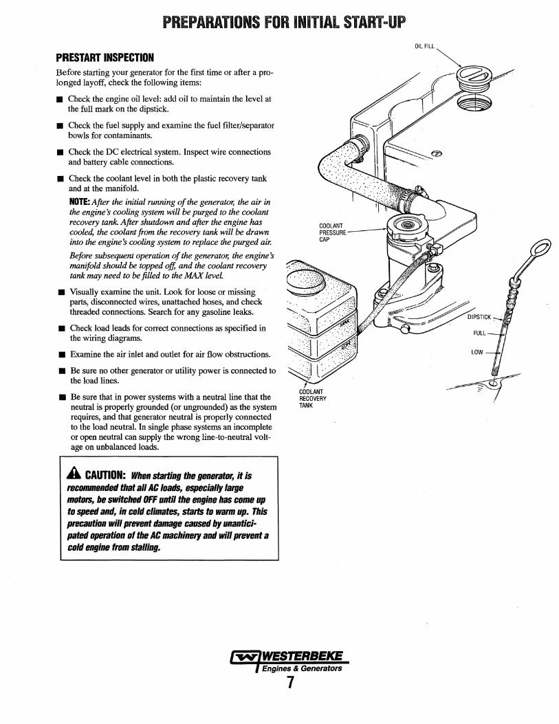
PREPARATIONS FOR INITIAL START-UP
PRESTART INSPECTION Before starting your generator for the first time or after a prolonged layoff, check the following items:
• Check the engine oil level: add oil to maintain the level at the full mark on the dipstick.
• Check the fuel supply and examine the fuel filter/separator bowls for contaminants.
• Check the DC electrical system. Inspect wire connections and battery cable connections.
• Check the coolant level in both the plastic recovery tank and at the manifold.
NOTE: After the initial running of the generator, the air in the engine's cooling system will be purged to the coolant recovery tank. After shutdown and after the engine has cooled, the coolant from the recovery tank will be drawn into the engine's cooling system to replace the purged air.
Before subsequent operation of the generator, the engine's manifold should be topped off, and the coolant recovery tank may need to be filled to the 1'MX level
• Visually examine the unit. Look for loose or missing parts, disconnected wires, unattached hoses, and check threaded connections. Search for any gasoline leaks.
• Check load leads for correct connections as specified in the wiring diagrams.
• Examine the air inlet and outlet for air flow obstructions.
• Be sure no other generator or utility power is connected to the load lines.
• Be sure that in power systems with a neutral line that the neutral is properly grounded (or ungrounded) as the system requires, and that generator neutral is properly connected to the load neutral. In single phase systems an incomplete or open neutral can supply the wrong line-to-neutral voltage on unbalanced loads.
A CAUTION: When starting the generator, It is reC81111111111ded that all AC loads, especially large moto15, be switched OFF until the engine has came up to speed and, in cold climates, starts to warm up. This precautiall will prevent damage caused by unantici· pated operation of the AC machinery and will prevent a cold engine from stalling.
COOLANT RECOVERY TANK
Engines & Generators
7
OIL FILL
OPERATING INSTRUCTIONS
GENERATOR PANEL Starting the Generator To start the generator, hold the momentary ON switch in the up (on) position, then hold the momentary START/OFF switch in the up (start) position (both switches are held up together). After approximately one second the starter will engage and the engine will crank. Once the engine is running, the starter will disengage, and the START/OFF switch may then be released to return to its center (run mode) position. Continue holding the ON switch until the engine has sufficient oil pressure, then release it to its center position. NOTE: Should the engine fail to start, release "both switches, wait 20 seconds, and try again. Never run the starter more than 20 seconds at a time.
START (MOMENTARY)
CENTER OFF/RUN IHL::...--- POSITION
OFF (MOMENTARY)
ON (MOMENTARY)
CENTER OFF/RUN UH~-- POSITION
START/OFF SWITCH ON SWITCH
Stopping the Generator To stop the generator, move the momentary START/OFF switch to the down (off) position then release it to the center (normal) position.
REMOTE PANEL Starting the Generator To start the generator, hold the momentary ON switch in the up (on) position (the green light will come on), then hold the momentary START/STOP switch in the up (start) position (both switches are held up together). After approximately one second the starter will engage and the engine will crank (the green light will dim). Once the engine is running (the green light will brighten), the starter will disengage and the START/STOP switch may then be released to return to its center (run mode) position. Continue holding the ON switch until the engine has sufficient oil pressure, then release it to its center position. NOTE: Should the engine fail to start, release "both switches, wait 20 seconds, and try again. Never run the starter more than 20 seconds at a time.
START (MOMENTARY)
STOP (MOMENTARY)
ON (MOMENTARY)
CENTER OFF/RUN POSITION
START/STOP SWITCH ON SWITCH
Stopping the Generator To stop the generator, move the momentary START/STOP switch to the down (stop) position then release it to the center (off/run mode) position. This will activate the remote control panel for START/STOP functions.
A CAUTION: Prolonged cranking intervals without the engine starting can result in filling the engine exhaust system with raw water. Tllis may happen because the pump is pumping raw water through the raw water cooling system during cranking. This raw water can enter the engine's cylinders by way of the exhaust manifold once the exhaust system fills. Prevent this tram happening by closing the raw water supply through-bull shutoff, draining the exhaust muffler, and co«et:ting the cause at the excessive engine cranking. Engine damage resulting tram raw water entry is not a warrantable issue; the owner/operator should keep this in mind.
EMERGENCY STOPPING If the generator does not stop using the START/OFF switch, remove the 8 amp fuse or disconnect the battery.
STARTING UNDER COLD CONDITIONS Make certain the lubricating oil conforms with the ratings for the prevailing temperature. Check the table under ENGINE LUBRICATING OIL. The battery should be fully charged to minimize voltage drop.
ABNORMAL STOP An abnormal stop is one in which the generator ceases to run and comes to a stop as a result of an operating fault which may cause damage to the engine, the generator, or create an unsafe operating condition. The fault stop conditions are:
1. Overspeed condition.
2. High engine temperature.
3. Low oil pressure.
4. High exhaust temperature.
Should a fault condition occur, the engine will shut down and the green LED light on the remote panel will go off indicating that a fault has occurred. Once detected, the fault should be located (see ENGINE TROUBLESHOOTING).
lwlWESTERBEKE ) Engines & Generators
8
BREAK-IN PROCEDURE/DAILY OPERATION
BREAK-IN PROCEDURE Once the generator has been started, check for proper operation and then encourage a fast warm-up. Run the generator between 20% to 60% of full load for the first 10 hours.
A CAUTION: Do not attempt ta break-in your genera· tor by running wlthallt a load.
After the first 10 hours of the generators' operation, the load can be increased to the full-load rated output; then periodically vary the load.
Avoid overload at all times. An overload is signaled by a smoky exhaust with reduced output voltage and frequency. Monitor the current being drawn from the generator and keep it within the generators' rating. Since the generator operates at 3600 rpm to produce 60 hertz, or at 3000 to produce 50 hertz, control of the generator's engine break-in is governed by the current drawn from the generator.
To protect against unintentional overloading of the generator, the generator's output leads should be routed through a circuit breaker that is rated at the rated output of the generator.
NOTE: Be aware of motor starting loads and the high current drawn required for starting motors. This starting amperage drawn can be 3 to 5 times normal running amperage (see GENERATOR INFORMATION).
CHECK UST Follow this checklist each day before starting your generator.
• Record the hourmeter reading in your log (engine hours relate to the maintenance schedule).
• Visually inspect the engine for fuel, oil, or water leaks.
• Check the oil level {dipstick).
• Check the coolant level in the coolant recovery tank.
• Check your fuel supply.
• Check the starting batteries (weekly).
• Check the drive belts for wear and proper tension (weekly).
• Monitor the control panel gauges.
• Check for abnormal noise such as knocking, friction, vibration and blow-back sounds.
• Confirm exhaust smoke: When the engine is cold - White Smoke. When the engine is warm - almost Smokeless. When the engine is overloaded - some Black Smoke.
NOTE: Some unstable running may occur in a cold engine. This condition should abate as normal operating temperature is reached and leads are applied.
A CAUTION: Ba not operate the generator for long periods of time without a load being plar:ed on the generator.
STOPPING THE GENERATOR Remove the major AC loads from the generator one at a time. Allow the generator to run for a few minutes to stabilize the operating temperature, (then see Stopping the Generator under OPERATING INSTRUCTIONS).
NOTE: After the first 50 hours of generator operation check the maintenance schedule for the 50 hour service check.
GENERATOR ADJUSTMENTS Once the generator has been placed in operation, there may be governor adjustments required for engine speed (hertz) during the engine's break-in period (first 50 hours) or after this period (see ENGINE SPEED (HERTZ) ADJUSTMENT under ENGINE ADJUSTMENTS. A no-load voltage adjustment may also be required in conjunction with the engine's speed adjustment (see GENERATOR INFORMATION).
l'W'IWESTERBEKE l Engines & Generators
g
SCHEDULED MAINTENANCE
Fuel Supply
Fuel/Water Separator
Engine Oil Level
Coolant Level
Drive Belts
MAINTENANCE SCHEDULE
A WARNING: Never attempt to perform any service while the engine is running. Wear the proper safety equipment sat:h as goggles and gloves, and use the correct tools far each jab. Disconnect the battery terminals when servicing any of the engine's DC electrical equipment.
NOTE: Many of the following maintenance procedures are simple but others are more difficult and may require the expert knowledge of a service mechanic.
CHECK HOURS OF OPERATION EACH EXPLANATION OF SCHEDULED DAY 50 100 250 500 750 1000 1250 MAINTENANCE
D Unleaded gasoline with octane rating of 89 or higher.
D Check for water and dirt in fuel (drain/replace filter if necessary).
D Oil level should indicate between FULL and LOW on dipstick.
D Check at recovery tank; if empty, check at manifold. Add coolant if needed.
D Inspect for proper tension (3/8" to 1/2" deflection) Weekly and adjust if needed. Check belt edges for wear.
Visual Inspection ol Engine D NOTE: Keep engine suiface clean. Dirt and Check for fuel, oil and water leaks. Inspect wiring oil will inhibit the engines ability to remain and electrical connections. Keep bolts & nuts tight. cooL Check for loose belt tension.
Spark Plugs D D D D D 0 Check gap; inspect for burning and corrosion.
Generator 0 D 0 0 0 0 0 Check that AC connections are clean and secure with no chafing - see GENERATOR INFORMATION for additional information.
carburetor Fiiter Screen 0 0 0 0 0 0 Initial change at 50 hrs, then change every 250 hrs.
Starling Batteries 0 0 Every 50 operating hours check electrolyte levels (and House Batteries) Weekly and make sure connections are very tight. Clean off
excessive corrosion.
Engine Oil 0 0 0 0 0 D· 0 Initial engine oil & filter change at 50 hrs., then change both every 100 hours.
*Adjust the Valve 0 0 0 Initial adjustment at 50 hrs., then every 500 hrs. Clearances
Air Screen (Flame Arrester) 0 Clean at 50 hours, then every 100 hours.
Exhaust System 0 0 0 0 Initial check at 50 hrs., then every 250 hrs. Inspect for leaks. Check siphon break operation. Check the exhaust elbow for carbon and/or corrosion buildup on inside passages; clean and replace as necessary. Check that all connections are tight.
Engine Hoses 0 0 0 D 0 0 Hose should be hard & tight. Replace it soft or spongy. Check and tighten all hose clamps.
Governor 0 0 0 0 0 Change oil every 250 hours. Lubricate linkage arm periodically.
*WESTERBEKE recommends this service be performed by an authorized mechanic. (continued)
Engines & Generators
10
SCHEDULED MAINTENANCE
Heat Exchanger
Raw Water Pump
Coolant System
*Starter Motor
Distributor
*Engine Cylinder Compression and Valve Clearance
*Engine Timing Belt
*Exhaust Elbow
MAINTENANCE SCHEDULE
NOTE: Use the engine lwurmeter gauge to log your engine lwurs or record your engine lwurs by running time.
CHECK HOURS OF OPERATION EACH EXPLANATION OF SCHEDULED DAY 50 100 250 500 750 1000 1250 MAINTENANCE
0 0 0 0 0 0 0 Clean or replace anode. Open heat exchanger end cap and clean out debris. Remove every 1000 hours for professional cleaning and pressure testing.
0 0 0 Remove pump cover and inspect impeller for wear; replace if needed. Also replace gasket Lubricate both when reassembling.
0 Drain, flush, and refill cooling system with appro-priate antifreeze mix.
0 0 Check solenoid and motor for corrosion. Remove and lubricate. Clean and lubricate the Start motor pinion drive.
0 0 Check ignition timing. Check condition of distribu-tor cap and rotor.
0 0 Incorrect valve clearance will result in poor engine performance; check compression pressure and timing, and adjust valve clearances.
0 Remove and replace.
NOTE: Failure to replace the timing belt at the rec-ommended inteival could result in timing belt fail-ure resulting in major damage to the engine.
0 Test exhaust elbow for casting integrity. Replace if casting is corroded or deteriorated. WARNING: A defective exhaust elbow can cause carbon monox-ide leakage!
*WESTERBEKE recommends this service be performed by an authorized mechanic.
Engines & Generators
11
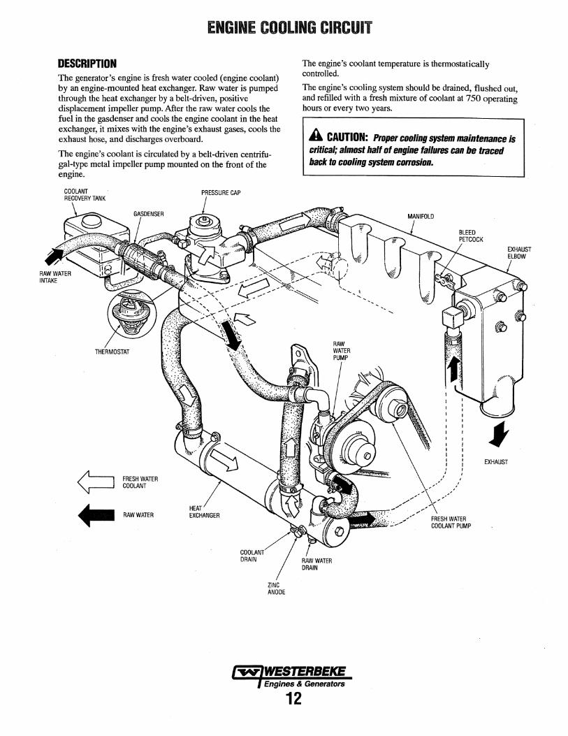
ENGINE COOLING CIRCUIT
DESCRIPTION The generator's engine is fresh water cooled (engine coolant) by an engine-mounted heat exchanger. Raw water is pumped through the heat exchanger by a belt-driven, positive displacement impeller pump. After the raw water cools the fuel in the gasdenser and cools the engine coolant in the heat exchanger, it mixes with the engine's exhaust gases, cools the exhaust hose, and discharges overboard.
The engine's coolant is circulated by a belt-driven centrifugal-type metal impeller pump mounted on the front of the engine.
FRESH WATER COOLANT
.. RAWWATER
PRESSURE CAP
HEAT EXCHANGER
ZINC ANODE
The engine's coolant temperature is thermostatically controlled.
The engine's cooling system should be drained, flushed out, and refilled with a fresh mixture of coolant at 750 operating hours or every two years.
A CAUTION: Proper cooling system maintenance is critical; almost half of engine failures can be traced back to cooling system corrosion.
EXHAUST
lwlWESTERBEKE l Engines & Generators
12
ENGINE COOLING CIRCUIT
THERMOSTAT A thermostat controls the coolant temperature as the coolant continuously flows through the closed cooling circuit. When the engine is first started ~e closed thennostat prevents coolant from flowing (some coolant is by-passed through a hole in the thermostat to prevent the exhaust manifold from overheating). As the engine warms up, the thermostat gradually opens. The thermostat is accessible and can be checked, cleaned, or replaced easily. Cairy a spare thermostat and gasket.
COOLANT RECOVERY TANK
THERMOSTAT TEST If you suspect a faulty thermostat, place it in a pm of water and bring to a boil. A working thermostat should open about 1/2".
DRAINING THE COOLANT Remove the manifold's pressure cap. Remove the block drain plug located on the left side of the engine block just under the manifold. Remove the beat exchanger drain plug. Flush the system. Re-install the two drain plugs. REFILLING THE COOLANT Slowly pour clean premixed coolant into the manifold.
NOTE: Open the air bleed petcock on the exhaust manifold to help remove air from the system. When a steady flow of coolant appears at the drain, close the water drain plug, fill the system and close the petcock.
Start the engine and bring it to opei::afulg temperature. Monitor the coolant in the manifold and add as needed. Fill the manifold to the filler neck and install the pressure cap.
Remove the cap on the coolant recovery tank and fill with coolant halfWay between WW and MAX, and replace the cap.
Run the engine and observe the coolant expansion flow into the recovery tank.
TO COOLANT RECOVERY TANK
FROM COOLANT RECOVERY TANK
COOLANT RETliACTION
COOLANT EXPANSION
MANIFOLD
After checking for leaks, stop the engine and allow it to cool. Coolant should drain back into the cooling system as the engine cools down. Add coolant to the recovery tank if needed. Oean up any spilled coolant.
NOTE: Periodically check the condition of the pressure cap. Ensure that the upper and lower rubber seals afe in good condition and check that the vacuum valve opens and closes tightly. Carry a spare cap.
A WARNING: Always t:llet:k the t:OOlallt level at the t:aalant recovery tank. B the engine is #Jot~ allow it ta cool before checking. HOT CDIJl.AllT and STEAM t:Bll
cause lllJURY or BEATH! Do not check the coolant at the •nifolll unless the engine is cool!
lw-IWEBTERBEKE ) Engines & Generators
13
ENGINE COOLING CIRCUIT
RAW WATER PUMP The raw water pump is a self-priming, rotary pump with a non-ferrous housing and a Neoprene impeller. The impeller has flexible blades which wipe against a curved cam plate within the impeller housing, producing the pumping action. On no account should this pump be run dry. There should always be a spare impeller and impeller cover gasket aboard (an impeller kit). Raw water pump impeller failures occur when lubricant (raw water) is not present during engine operation. Such failures are not warrantable, and operators are cautioned to make sure raw water flow is present at start-up. The raw water pump should be inspected periodically for broken or tom impeller blades. See MAINTENANCE SCHEDULE.
RAW WATER IN
FROM GASDENSER
t TO HEAT EXCHANGER
RAW WATER PUMP
CHANGING lHE RAW WATER PUMP IMPELLER NOTE: Coat the replacement impeller blade tips with petroleum jelly before installing.
A CAUTION: The raw water intake ra/re (seacock} l1lllSI be closed when servicing any compolltlllls of the raw watet system, and lllllSI be ftl-Olllllled before start· Ing the engine.
HEAT EXCHANGER Cool raw water flows through the inner tubes of the heat exchanger. As the engine coolant passes around these tubes the heat of the internal engine is conducted to the raw water which is then pumped into the exhaust system and discharged. The engine coolant (now cooled) flows back though the engine and the circuit repeats itself.
The engine coolant and raw water are independent of each other; this keeps the engine's water passages clean from the harmful deposits found in raw water.
NEW
TO ENGINE BLOCK
t. FROM RAW WATER PUMP
·: t.:::
I REPLACE REPLACE
ZINC ANODES
CLEAN AND REPLACE
HEAT EXCHANGER
END CAP
A zinc anode (or pencil) is located in the raw water cooling circuit within the heat exchanger. The purpose of the zinc anode is to sacrifice itself to electrolysis action taking place in the raw water cooling circuit, thereby reducing the effects of electrolysis on other components of the system. The condition of the zinc anode should be checked monthly and the anode cleaned or replaced, as required. Spare anodes should be carried onboard. The area in the exchanger where the . anode is located should periodically be cleaned of anode debris. Take care not to lose the small 0-ring that nestles between the heat exchanger end gasket and the cover.
. D9'1VE BELT ADJUSTMENT
fA CAUTION: The drive belt lllllSt be propet1y tensioaed ·-,,,,.Ille belt-ttiren water pmnps to funt:tion /lfOlltllly.
For the raw water pump/fresh water pump drive belt tension adjustment procedure, see DRIVE BELTS ADJUSTMENT under ENGINE ADJUSTMENTS.
1-WIWESTERBEKE f Engines & Generators
14
FUEL SYSTEM
GASOLINE Use unleaded 89 octane or higher gasoline. When fueling, follow U.S. Coast Guard regulations, close off all hatches and companionways to prevent fumes from entering the boat, and ventilate after fueling.
NOTE: The generator compartment should have a gasoline fume detector/alarm properly installed and working.
A WARNING: Shut off the fuel valve at the tank when servicing the fuel system. Take care in catching any fuel that may spill. DD NOT allow any smoking, open flames or other sources of fire near the fuel system when servicing. Ensure proper ventilation exists when servicing the fuel system.
CA~BURETOR
The carburetor is a single barrel downdraft type with a solenoid-activated electric choke and electric fuel shutoff solenoid.
CARBURETOR
GASOLINE/WATER SEPARATOR AND FILTER A primary fuel filter of the water separating type must be installed between the fuel tank and the engine to remove water and other contaminants from the fuel before they can be carried to the fuel system on the engine.
Most installers include a type of filter/water separator with the generator installation package as they are well aware of the problems that contaminants in the fuel can cause.
These gasoline filters must have metal bowls (not "seethrough") to meet U.S. Coast Guard requirements. The metal bowls have drain valves to use when checking for water and impurities.
FUEL PUMP
GASOLINE/WATER SEPARATOR
Periodically check the fuel connections to and out of the pump and make sure that no leakeage is present and that the fittings are tight and secure. The DC ground connection at one of the pump's mounting bolts should be clean and well secured by the mounting bolt to ensure proper pump operation.
A WARNING: Fuel leakage at the fuel pump or its connections is a fire hazard and should be corrected. Make sure proper ventilation exists whenever servicing fuel system components.
GASDENSER The gasdenser consists of a portion of the fuel line that is coiled around the raw water intake line and insulated. It is located between the raw water intake and the raw water pump. The gasdenser cools the fuel to prevent vapor lock.
~·
TO CARBURETOR
Engines & Generators
15
ENGINE LUBRICATING Oil
ENGINE Oil Use a good brand of engine oil with an API and SAE designations as listed in the SPECIFICATION Section of this manual. Change the engine oil and filter after an initial 50 hours of engine break-in operation. Then follow the oil and filter change interval as specified in the MAINTENANCE SCBEDULE in this manual.
Westerbeke Corporation does not approve pr disapprove the use of syn~tic oils. If synthetic oils are used, engine break:in must be peiformed using conventional oil. Oil change intervals must be as listed in the MAINTENANCE SCHEDULE section of this manual and not be extended if synthetic oils are used.
NOTE: The information above supersedes all previous statements regarding symhetic oil.
CHANGING THE ENGINE Oil The engine oil should be warm. Remove the oil drain hose from its attachment bracket and lower it into a container and allow the oil to drain, or attach a pump to the end of the drain hose and pump the old oil out. Make sure the oil drain hose is properly secured in its holder after all of the old oil bas been drained.
Always observe the old oil as it is removed. A yellow/gray emulsion indicates the presence of water in the oil. Although this condition is rare, it does require prompt attention to prevent serious damage. Call a competent mechanic if water is present in the oil. Raw water present in the oil can be the result of a fault in the exhaust system attached to the engine and/or a siphoning through the raw water cooling circuit into the exhaust, filling it up into the engine.
A WARNING: llsetl engine ail contains harmful contaminants. Avoid prolonged skin contact. Clean skin and nails tba1ougbly asing soap and water. Launde1 01
dist:anl t:latbing a1 mgs containing used ail. Discanl used ail prapedy.
REPLACING THE OIL FILTER When removing the used oil filter, you may find it helpful to punch a hole in the upper and lower portion of the old filter to drain the oil into a container before removing it. This helps to lessen spillage. An automotive filter wrench should be helpful in removing the old oil filter. Place some paper towels and a plastic bag around the filter when unscrewing it to catch any oil that's in the filter. Inspect the old oil filter as it is removed to make sure that the rubber sealing gasket comes off with the old oil filter. If this rubber sealing gasket remains sealed against the oil filter adapter, gently remove it. When installing the new oil filter element, wipe the filter gaSket's sealing surface on the oil filter adapter free of oil and apply a thin coat of clean engine oil to the rubber gasket on the oil filter. Screw the filter onto the threaded oil fiherinippJe, and. tighten the filter firmly by band.
NOTE: Use genuine WESTERBEKE oil filters. Generic filters are not recommended.
REFWNG THE ml SUMP Add fresh oil through the valve cover. After refilling the oil, run the engine for a few moments while checking the engine's oil pressure. Make sure there is no leakage around the new oil filter or from the oil drain system, and then stop the engine. Then check the quantity of oil with the lube oil ~pstick. Fill to, but not over, the FULL mark on the dipstick.
lwfWESTEllBEKE l Engines & Generators
16
REMOTE OIL FILTER (OPTIONAL)
INSTALLATION This popular accessory is used to relocate the engine's oil filter from the engine to a more convenient location such as an engine room bulkhead.
NOTE: Refer to REPLACING THE OIL FILTER for instructions on removing the oil filter.
APPLY A THIN COAT OF CLEAN OIL TO THE 0-RING WHEN INSTALLING THIS Kit THREAD THE KIT ON, THEN TIGHTEN (BY HAND) AN ADDITIONAL 3/4 TURN AFTER THE O·RING CONTACTS THE BASE.
To install, simply remove the engine oil filter and thread on WESTERBEKE's remote oil filter kit as shown. Always install this kit with the oil filter facing down as illustrated.
Contact your WESTERBEKE dealer for more information.
NOTE: Westerbeke is not responsible for engine failure due to incorrect installation of the Remote Oil Filter.
FASTEN SECURELY TO A BULKHEAD (SCREWS ARE OWNER SUPPLIED).
APPLY A THIN COAT OF CLEAN OIL TO THE FILTER GASKET WHEN INSTALLING. WHEN THE FILTER CONTACTS THE BASE, TIGHTEN IT (BY HAND) A 3/4 TURN MORE.
l'W'lWES'l'ERBEICE f Engines & Generators
17
DC ELECTRICAL SYSTEM
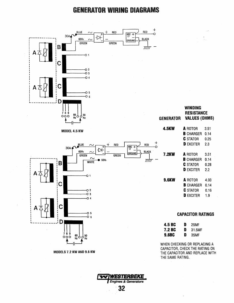
12-VOLT DC CONTROL CIRCUIT The DC Circuit on the BCGTC functions to start, operate and stop the generator's engine. The circuit is best understood by reviewing the DC Wiring Diagram and Wiring Schematic. The engine's DC wiring is designed with three simple basic circuits: start, run and stop.
The engine has a 12 volt DC electrical control circuit that is shown on the Wiring Diagrams. Refer to these diagrams when troubleshooting or when servicing the DC electrical system or the engine.
BATIERIES
A CAUTION: To avoid damage to the battery charg· ing circut, never shut off the engine battery switch while the engine is running. Shut off the engine battery switch, however. to avoid electrical shorts when work· ing on the engine's electrical circuit.
Specifications The minimum recommended capacity of the battery used in the engine's 12-volt DC control circuit is 300 CCA.
Battery Maintenance Review the manufacturer's recommendations and then establish a systematic maintenance schedule for your engine's starting batteries and house batteries.
• Monitor your voltmeter for proper charging during engine operation.
• Check the electrolyte level and specific gravity with a hydrometer.
• Use only distilled water to bring electrolytes to a proper level.
• Make certain that battery cable connections are clean and tight to the battery posts (and to your engine).
• Keep your batteries clean and free of corrosion.
A WARNING: Sulfuric acid in lead batteries can cause severe bums on skin and damage clothing. Wear protective gear.
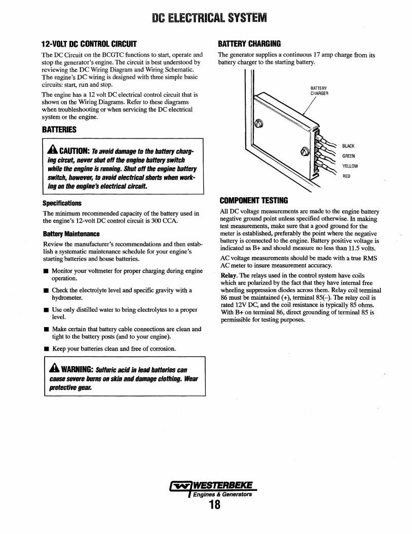
BATTERY CHARGING The generator supplies a continuous 17 amp charge from its battery charger to the starting battery.
COMPONENT TESTING
BATTERY CHARGER
BLACK
GREEN
YELLOW
RED
All DC voltage measurements are made to the engine battery negative ground point unless specified otherwise. In making test measurements, make sure that a good ground for the meter is established, preferably the point where the negative battery is connected to the engine. Battery positive voltage is indicated as B+ and should measure no less than 11.5 volts.
AC voltage measurements should be made with a true RMS AC meter to insure measurement accuracy.
Relay. The relays used in the control system have coils which are polarized by the fact that they have internal free wheeling suppression diodes across them. Relay coil terminal 86 must be maintained(+), terminal 85(-). The relay coil is rated 12V DC, and the coil resistance is typically 85 ohms. With B+ on terminal 86, direct grounding of terminal 85 is permissible for testing purposes.
ENGINE ADJUSTMENTS NOTE: WESTERBEKE recommends that the following engine
· adjustments be performed by a competent engine mechanic. The information below is provided to assist the mechanic.
ENGINE SPEED (HERR) ADJUSTMENT
Governor The belt-driven, ~echanically operated governor maintains the engine's rpm under various load conditions. Engine speed determines the hertz and voltage output of the generator.
Governor Adjustments Operate the generator to bring the unit up to operating temperature before adjusting the governor.
NOTE: If the governor is severely out of adjustmen~ manually adjust the linkage at no-load to obtain a safe output voltage before proceeding with the adjustment.
There are three adjusting points on the governor (see illustration).
1. Increase/Decrease SpeedAdjustment. This adjusting bolt sets the no-load speed of the engine. (The linkage arm between the governor arm and throttle lever should be adjusted to hold the throttle full open when the engine is not running.) Make sure this linkage moves freely and that the ball joint connectors are properly lubricated. Use graphite lube for this purpose. Disconnect the ball joint and apply graphite lube to the inside of the joint.
2. Hunting/RegulationAqjustment. If the variation in engine speed between no-load and full-load is too great, adjust this eye bolt to draw the spring closer to the lever hub. The increase/decrease speed bolt may need to be adjusted as well.
If the governor surges under load, adjust this eye bolt to move the spring away from the lever hub (check speed adjustment).
3. Bumper Screw Atjustment. This screw is used to remove a no-load siifge ONLY.NEVER turn the bumper screw into the governor so far that it increases the no-load speed.
Governor Maintenance 1. Periodically lubricate the linkage arm attaching points at
the governor arm and throttle lever. Use a graphite lubricant or equivalent.
NOTE: Free movement of this linkage arm is important for proper governor/throttle operation.
3. Change the governor oil every 250 hours of operation.
To change the oil, remove the governor from the engine, remove the oil fill and the fill level plug, and drain all the oil. Reinstall on the engine and fill with 3 ounces of 10/30 engine oil. Replace the plugs.
4. Periodically adjust the governor belt tension (see DRIVE BELTS ADJUSTMENT). Since belts stretch slightly, this stretching will, to some degree, affect the govenor's action.
TORQUING THE CYUNDER HEAD BOLTS After the initial break-in period (approximately 50 hours), the cylinder h.ead bolts should be re-torqued.
Tighten the cylinder head bolts according to the sequence shown. Make sure the engine is cold when this is done, and loosen one head bolt one-half tum and then tighten it between 43-51 lb-ft (60-70 Nm). Then proceed to the next head bolt in the sequence. Tighten the RS (rocker cover stud) securely.
6 4 2 7
LINKAGE ARM
FRONTOF .~ ENGINE ~
HUNTING/ REGULATION ADJUSTMENT
GOVERNOR
OIL FILL
8
lwlWESIERBEICB f Engines & Generators
22
1 3 5
ENGINE ADJUSTMENTS NOTE: WESTERBEKE recommends that the following engine adjustments be performed by a competent engine mechanic. The information below is provided to assist the mechanic.
VALVE CLEARANCE ADJUSTMENT NOTE: Retorque the cylinder head bolts before adjusting the engine's valves (see WRQUING THE CYLINDER HEAD BOLTS).
1. Remove the rocker cover and gasket.
2. Adjust the intake and exhaust valves in the firing order of the engine (1-3-2), as follows:
Rotate the crankshaft in its normal direction of rotation, placing the No. 1 piston at the IDC (fop Dead Center) of its compression stroke with the intake and exhaust valves completely closed. Then adjust the intake and exhaust valve clearances for cylinder No. 1.
Valve clearances: Intake valves - 020 mm (.008 in) Exhaust valves - 0.30 mm (.012 in)
Repeat the above procedure to adjust the intake and exhaust valves for No. 3 cylinder, then repeat this procedure once more to adjust the intake and exhaust valves for No. 2 cylinder.
3. Replace the rocker cover along with a new roc~er cover gasket.
The choke solenoid is a 12 volt DC operated unit that functions to close the choke plate in the carburetor when the ON switch is depressed during engine start-up.
The choke solenoid de-energizes.once the engine starts and the ON switch is released. Some unstable running may be present when the engine starts cold but should smooth out as the engine reaches operating temperature.
Keep this solenoid dry and periodically lubricate the linkage between the solenoid and the choke lever.
CHOKE SOLENOID
IGNITION TIMING 1. Attach a timing light to the #1 spark plug and mark the
front timing pointer to indicate 18°. Locate the timing mark on the crankshaft pulley and mark it with white chalk or a crayon.
2. Start the engine and warm it up to its normal operating temperature. Make sure the generator is operating without· a loa.d on it.
3. Using the timing light, align the timing mark in the front crankshaft pulley so it is just slightly before the first timing pointer. Do this by loosening and slowly rotating the distributor body. Use the following timing specifications:
Tuning Specifications: 18° ± .5° BIDC at 3600 rpm (no load on generator)
IGNITION TIMING
SPARK PLUGS The spark plugs should be cleaned and regapped after the first 50 hour break-in period, then inspected every 250 hours thereafter and replaced as needed.
A WARNING: Do not remore the spark plugs while the engine is hot. Allow the engine to caal befOlll removing them. ·
NOTE: Loi-tite Anti-Seize applied to the threaded portion of the spark plugs will retard corrosion, maldng fature removal of the spark plugs easier. ·
SPARK PLUG INSPECTION
BURNT CONDITION
DAMAGE AND OITTRIORATION
DAMAGE
j,w-IWESTERBEKE I Engines & Generators
23
ENGINE ADJUSTMENTS NOTE: WESTERBEKE recommends that the following engine adjustments be performed by a competent engine mechanic. The information below is provided to assist the mechanic.
CARBURETOR ADJUSTMENT Basic Jet Adjustment is performed with the generator operating. Screw the jet slowly in until it seats, then back it out 1-1/2 to 2 turns.
NOTE:An idle mixture jet adjusted too far off its seat can induce a sooty exhaust discharge at engine start-up and shutdown.
NOTE:At idle speed, oil pressure will be lower than the rating of the oil pressure switch. Jump this switch to prevent engine shutdown at idle speed.
Run Mixture Jet. This mixture jet is presized at the factory and is not adjustable. The idle mixture jet adjustment can be made in the 3600 rpm range to improve engine performance.
CARBURETOR
DRIVE BELTS ADJUSTMENT The drive belts must be properly tensioned. Excessive drive belt tension can cause rapid wear of the belt and reduce the service life of the fresh water pump's bearing. A slack belt or the presence of oil on the belt can cause belt slipping, resulting in high operating temperatures.
The BCGTC generator has two drive belts, one for the governor and one for the raw water pump/fresh water pump. The tension adjustment procedure for both belts is as follows:
1. Remove the belt guard.
2. To adjust the governor drive belt, loosen the two governor mounting bolts.
To adjust the raw water pump/fresh water pump drive belt, loosen the two raw water pump mounting bolts.
3. With the belt(s) loose, inspect for wear, cracks and frayed edges, and replace if necessary.
4. To loosen or tighten the governor drive belt, slide the governor in or out as required, then retighten its mounting bolts.
To loosen or tighten the raw water pump/fresh water pump drive belt, slide the raw water pump in or out as required, then retighten its mounting bolts.
S. The drive belts are properly adjusted if they can be deflected no less than 3/8 inch (lOmm) and no more than 1/2 inch ( 12mm) as the belt is depressed with the thumb at the midpoint between the two pulleys on the longest span of the belt.
NOTE: Maintain a 22 lb pressure to the belt's outer face for proper belt operation. Spare belts should always be carried on board.
A WARNING: llevet attempt to cllet:k 01 adjust a dtire beft tension while the engine Is in operation.
6. Operate the generator for about 5 minutes, then shut down the generator and recheck the belt(s) tension.
7. Replace the belt guard.
lwfWESTERBEICE Engines & Generators
24
ENGINE ADJUSTMENTS NOTE: WESTERBEKE recommends that the following engine adjustments be performed by a competent engine mechanic. The information below is provided to assist the mechanic.
TIMING BELT INSPECTION AND REPLACEMENT Timing Belt Removal
A CAUTION: Water or oil on the timing belt severely rsdut:es the serrit:B life of the belt. Keep the timing belt sprocket and tensioner free of oil and grease. These parts should nerer be cleaned. Replace if seriously contaminated with dirt or oil. If oil is evident on these parts, t:bet:k the front case, oil PlllllP oil seals, and t:alllShalt ail seals tor a possible oil leak.
1. Tum the crankshaft clockwise to align the timing mark on the camshaft sprocket and timing belt rear cover.
NOTE: always turn the crankshaft clockwise. TIMING MARK
2. Remove the plug on the left surface of the cylinder block and insert a rod with a diameter of 8mm (031in.) to lock the' counterbalance shaft.
NOTE: Be sure to use an inserting rod with a diameter of 8mm (0.31 in.).
3. loosen the timing belt tensioner nut.
4. Move the timing belt tensioner toward the water pump, and temporarily tighten the nut to hold the tensioner in that position.
WATER PUMP
5. Remove the timing belt.
NOTE: If the timing belt is to be reused, draw an arrow on the belt back to indicate the direction of rotation (clockwise).
camshaft Sprocket Removal
1. Remove the bolt without turning the camshaft.
Oil Pump Sprocket Flange Nut Removal.
1. Remove the plug from the left side of the cylinder block.
2. Insert an 8 mm (031 in.) diameter round bar to lock the counterbalance shaft.
3. Remove the nut.
OIL PUMP SPROCKET NUT
lwlWESIERBEKE f Engines & Generators
25
ENGINE ADJUSTMENTS NOTE: WESTERBEKE recommends that the following engine adjustments be performed by a competent engine mechanic. The information below is provided to assist the mechanic.
Crankshaft Bolt Removal
1. Lock the crankshaft in position.
NOTE: Do not tum the crankshaft.
2. Remove the crankshaft bolt.
Tuning BeH Inspection
Replace the belt if any of the following conditions exist:
1. Hardening of back rubber-back side is glossy, without resilience, and leaves no indent when pressed with fingernail.
2. Cracks on rubber back.
3. Cracks or peeling of canvas.
4. Cracks on tooth bottom.
5. Cracks on belt.
6. Abnormal wear of belt sides. The sides are normal if they are sharp as if cut by a knife.
7. Abnormal wear on teeth.
8. Tooth missing and canvas fiber exposed.
1. 2.
~~ '- '><..,_. CRACKS~ ~ OR PEELING
3.
5.
7.
Tensioner Inspection
4.
6.
ROUNDED EDGE
ABNORMAL WEAR (FLUFFY STRAND)
TOOTH MISSING AND CANVAS
~R~
8.
1. Replace the tensioner if the pulley binds, rattles or is noisy when turned.
Flange Installation
1. Mount the flange so that its side shown by the heavy arrow in the illustration faces toward the sprocket.
FLANGE
r------1 I L------
WASHER
-~--=lli CRANKSHAFT
Crankshaft Bolt Installation
1. Lock the crankshaft.
NOTE: Do not tum the crankshaft.
2. 'lighten the crankshaft bolt to the specified torque.
Oil Pump Sprocket Flange Nut Installation
1. Insert a round bar into the plug hole in the left side.of the cylinder block to keep the counterbalance shaft from turning.
2. Install the oil pump sprocket.
3. 'lighten the nut to the specified torque.
Camshaft Sprocket Bott Installation
1. Tighten the bolt to the specified torque.
BOLT
lwlWESTERBEICE ) Engines & Generators
26
ENGINE ADJUSTMENTS NOTE: WESTERBEKE recommends that the following engine adjustments be performed by a competent engine mechanic. The information below is provided to assist the mechanic.
Tensioner Spring/Tuning Tensioner Installation
1. Install the tensioner spring and timing belt tensioner.
2. Hook the tensioner spring onto the bend of the timing belt tensioner bracket and the stopper pin on the cylinder block.
3. Move the timing belt tensioner as close as possible to the water pump; temporarily tighten the tensioner nut.
Timing Belt Installation
1. Align the triangular marking on the camshaft sprocket with a marking on the timing belt rear cover.
2. Align tb.e notch in the crankshaft sprocket flange with the marking on the front case.
3. Align the triangular marking on the oil pump sprocket with the marking on the front case, and then insert a 65 mm (2.56 in.) or longer, 8 mm (031 in.) diameter round bar into the plug hole in the left side of the cylinder block&·~;;;;;~~
TRIANGULAR. MARKING ON CAMSHAFT SPROCKET
At this time, check that the moveable range of teeth on the oil pump sprocket is according to specifications.
Standard value: 4 to 5 teeth in forward direction 1 to 2 teeth in reverse direction
FORWARD
REVERSE
OIL PUMP SPROCKET
4. If the movable range of the oil pump sprocket exceeds the specified range, correct as follows:
a. Pull out the round bar from the plug hole in the left side of the cylinder block.
b. Tum the oil pump sprocket one tum at a time until the round bar can again be inserted.
c. Check that the movable range of the oil pump sprocket is in the specified value.
5. Set the timing belt over the crankshaft sprocket and then over the oil pump sprocket and camshaft sprocket, in that order.
NOTE: Ensure that the tension side of the timing belt is not slack. Keep the round bar inserted until the timing belt has been placed. After this step, be sure to remove the round bar.
6. Apply counterclockwise force to the camshaft sprocket to make the belt taut on the tension side, and make sure that all timing marks are lined up.
TENSION SIDE
7. Loosen the temperorarily tightened tensioner nut on the water pump side 1 or 2 turns, and tension the belt making use of spring force.
l'W'IWESTERBEKE l Engines & Generators
27
ENGINE ADJUSTMENTS NOTE: WESTERBEKE recommends that the following engine adjustments be performed by a competent engine mechanic. The information below is provided to assist the mechanic.
8. Turn the crankshaft c'/ockwise by nine camshaft sprocket teeth (81 j to align the timing mark on the camshaft sprocket with the tensioner set mark on the timing belt rear cover.
A CAUTION: This opendion is performBd to give a ptapet tension to the timing belt, so do NOT tum the crankshaft caunten:lot:ltwise and push the belt to check the tension.
9. Make sure that the timing belt teeth are engaged with the camshaft sprocket teeth along the portion of the sprocket shown by the curved arrow in the illustration below. Then tighten the tensioner nut.
10. Pull the timing belt in the center of the tension side toward the sealing gasket line for the belt cover, as illustrated. Make sure that the clearance between the back of the belt and the sealing line is the standard value.
Standard Value: 12mm (0.47in.)
ll. Pull out a rod from the plug hole on the left surface of the cylinder block and apply the specified sealant. Then tighten the plug to the specified torque.
Specified sealant value: 3M A1D Part No. 8660 or equivalent
Tightening torque: 15-22 Nm (11-16 ft.lbs.)
lwlWES'TEllBEKE l Engines & Generators
28
ENGINE TROUBLESHOOTING
The following troubleshooting tables are based upon certain engine problem indicators and the most likely causes of the problems.
PROBLEM PROBABLE CAUSE
Engine does not 1. Voltage drop at starter solenoid crank. terminal.
2. Engine 25A circuit breaker has tripped.
3. Battery is low or dead. 4. Loose battery connections. 5. Faulty wire connection. 6. Faulty start switch. 7. Faulty start relay (K1) (Jump). 8. Faulty starter solenoid 9. Raw water filled cylinders.
Engine cranks but 1. Out of fuel. fails to start. 2. Engine is flooded.
a. Carburetor float needle valve open or damaged. Clean or replace the needle valve.
b. Float in carburetor is leaking. Repair or replace float.
c. Float chamber gasket damaged or securing screws are loose. Replace gasket and/or tighten screws.
3. Fuel pump inoperative. 4. Worn or faulty spark plugs. 5. High tension wires grounding
module). 8. Faulty run relay (K2) (Jump). 9. Timing belt.
10. No engine compression.
When troubleshooting indicates an electrical problem, see the DC ELECTRICAL SYSTEM WIRING DIAGRAM AND SCHEMATIC, as these may reveal other possible causes of the problem which are not listed below.
PROBLEM PROBABLE CAUSE
Engine starts, runs 1. Faulty shutdown switch, and then shuts (oil pressure, water, exhaust down. temperature or overspeed).
2. High engine water or exhaust temperature.
3. Dirty fuel/water separator filter. 4. Mechanical check valve at the fuel
supply faulty (if installed). 5. Low oil level in sump. 6. Faulty fuel pump. 7. Faulty engi_ne temperature sensor.
Engine starts, runs 1. Fuel line restriction. but does not come 2. Mechanical check valve at the up to speed. - fuel supply is faulty.
3. Throttle plate binding.
4: Faulty fuel pump. 5. Faulty wire connection. 6. AC generator overload. 7. High exhaust pressure. 8. Hj[h exhaust J!!"essure.
Engine hunts. 1. Low battery voltage. 2. Generator is overloaded. 3. Cracked distributor cap. 4. Faulty high tension wires. 5. Faulty fuel pump. 6. High exhaust back-pressure. 7. Valves are out of adjustment
NOTE: When troubleshooting the overspeed board, to by-pass lift the T3 connectionoff its terminal and move to the vacant T4 spade connector. Start the engine and if the engine continues to run when the ON switch is released, the overspeed switch is at fault. Refer to the OVERSPEED WIRING DIAGRAM.
Engines & Generators
29
ENGINE TROUBLESHOOTING
PROBLEM PROBABLE CAUSE PROBLEM PROBABLE CAUSE
Engine misfires. 1. Poor quality fuel. High oil pressure. 1. Dirty oil or wrong SAE type oil in the 2. Incorrect timing. engine.
3. Dirty flame arrester. 2. Relief valve is stuck.
4. Cracked distributor cap. No DC charge to the 1. Faulty connections to 5. Faulty ignition wires. starting battery. battery voltage regulator. 6. Spark plugs are worn. 2. Faulty battery voltage regulator.
7. High exhaust back-pressure. 3. Faulty bridge rectifier.
8. Valve clearances are incorrect. 4. Faulty generator charger
Engine backfires. 1. Spark plug wires are connected windings.
wrong. Blue exhaust smoke 1. Lube oil is diluted. 2. Incorrect timing. 3. Engine is flooded. See Engine is
discharge from the 2. High lube oil level. engine. 3. Crankcase breather hose is clogged.
flooded under Engine cranks but 4. Valves are worn or adjusted tails to start. incorrectly.
4. Dirty flame arrester. 5. Piston rings are worn 5. Cracked distributor cap. or unseated. 6. High exhaust back-pressure. Black exhaust smoke 1. Dirty flame arrester.
Engine overheats. 1. Coolant loss. Pressure test cooling system.
discharge from the 2. Faulty carburetor. engine.
2. Faulty raw water pump impeller. 3. Belts are loose or broken.
Poor performance 1. Main jet clogged. Remove and clean. at generator speed. 2. Carburetor inlet filter clogged.
4. Raw water pump worn.· Remove and clean. 5. Faulty thermostat. 3. Fuel pump clogged. Remove and
Low oil pressure. 1. Low oil level. replace.
2. Wrong SAE type oil in the engine. 3. Wrong type oil filter.
4. Air intake filter screen dirty. Remove and clean.
USE OF ELECTRIC MOTORS The power required to start an electric motor is considerably more than is required to keep it running after it is started. Some motors require much more current to start than others. Split-phase (AC) motors require more current to start, under similar circumstances, than other types. They are commonly used on easy-starting loads, such as washing machines, or where loads are applied after the motor is started, such as small power tools. Because they require 5 to 7 times as much current to start as to run, their use should be avoided, whenever possible, if the electric motor is to be driven by a small generator. Capacitor and repulsion-induction motors require from 2 to 4 times as much current to start as to run. The current required to start any motor varies with the load connected to it. An electric motor connected to an air compressor, for example, will require more current than a motor to which no load is connected.
In general, the current required to start 115 volt motors connected to medium starting loads will be approximately as follows:
AMPS FOR AMPS FOR MOTOR SIZE RUNNING STARTING
(HP) (AMPERES) (AMPERES)
1/6 3.2 6.4 T022.4
1/4 4.6 9.2TO 32.2
1/3 5.2 10.4 TO 72.8
1/2 7.2 14.4 TO 29.2
3/4 10.2 20.4 T040.8
1 13 26T052
NOTE: In the above table the maximum "AMPS FOR STARTING" is more for some small motors than for larger ones. The reason for this is that split-phase (the hardest starting types) are used in the smaller motors only.
Because the heavy surge of current needed for starting motors is required for only an instant, the generator will not be damaged if it can bring the motor up to speed in a few seconds. If difficulty is experienced in starting motors, turn off all other electrical loads and, if possible, reduce the load on the electric motor.
REQUIRED OPERATING SPEED Although individual units may vary slightly, the normal voltage and frequency of typical 60 (50) hertz engine-driven generators described in this manual are approximately as follows: run first with no load applied, then at half the generator's capacity, and finally loaded to its full capacity as indicated on the generator's data plate.
The output voltage should be checked periodically to ensure proper operation of the generating plant and the appliances it supplies.
GENERATOR FREQUENCY ADJUSTMENT a Frequency is a direct result of engine/generator speed, as
indicated by the following:
a When the generator is run at 3600 rpm, the AC voltage output frequency is 60 hertz.
a When the generator is run at 3000 rpm, the AC voltage output frequency is 50 hertz.
Therefore, to change the generator's frequency, the generator's drive engine's speed must be changed. A reconfiguring of the AC output connections at the generator must also be made.
GENERATOR MAINTENANCE Maintaining cleanliness is important. Do not allow salt, dust, or carbon from engine exhaust to build up on either the generator or its engine.
REAR BEARING
STATOR
CAPACITORP
GENERATOR COMPONENTS
lwlWESTERBEICE l Engines & Generators
31
GENERATOR WIRING DIAGRAMS
;------- --- -, I I I I
I :9
I 2 ,, I 3 I
Aill\cb; L ________ ~_Joll! JL
L;~Hz
MODEL4.5 KW
r------------ ~-- 50Hz I : B WHITE
I 2 I I 3 I
m·~4 Ailljc~:
I
L __________ J D~"
lii ~11Hz ~~
MODELS 7 .2 KW AND 9.6 KW
RED +
BLACK
GREEN
32
WINDING RESISTANCE
GENERATOR VALUES (OHMS)
4.SKW
7.2KW
9.6KW
4.5 BC 7.2 BC 9.6BC
A ROTOR 3.51 B CHARGER 0.14 C STATOR 0.25 D EXCITER 2.3
A ROTOR 3.51 B CHARGER 0.14 C STATOR 0.28 D EXCITER 2.2
A ROTOR 4.03 B CHARGER 0.14 C STATOR 0.16 D EXCITER 1.9
CAPACITOR RATINGS
D 25MF D 31.5MF D 35MF
WHEN CHECKING OR REPLACING A CAPACITOR, CHECK THE RATING ON THE CAPACITOR AND REPLACE WITH THE SAME RATING.
MODELS 7.2KW AND 9$KW C - STATOR WINDING D - CAPACITOR WINDING
~= N
A WARNING: When changing from 60Hz to SOHz, make certain the ground wire {white & green stripe) is properly repositioned according to this diagram.
Engines & Generators
33
L
120 VAC 60 HZ
(CONNECT JUMPER)
240/120 VAC 60 HZ
(REMOVE JUMPER)
220 VAC 50 HZ
(REMOVE JUMPER)
LAY-UP & RECOMMISSIONING
GENERAL Many owners rely on their boatyards to prepare their craft, including engines and generators, for lay-up during the offseason or for long periods of inactivity. Others prefer to accomplish lay-up preparation themselves.
The procedures which follow will allow you to perform your own lay-up and recommissioning, or will serve as a checklist if others do the procedures.
These procedures should provide protection for your engine/generator during a lay-up and also help familiarize you with its maintenance needs.
If you have any questions regarding lay-up procedures, call your local servicing dealer. He will be more than willing to provide assistance.
FRESH WATER COOLING SYSTEM A 50-50 solution of antifreeze and distilled water is recommended for use in the fresh water cooling system at all times. This solution may require a higher concentration of antifreeze, depending on the area's winter climate. Check the solution to make sure the antifreeze protection is adequate.
Should more antifreeze be needed, drain an appropriate amount from the engine block and add a more concentrated mixture. Operate the engine to ensure a complete circulation and mixture of the antifreeze concentration throughout the cooling system. Then recheck the antifreeze solution's strength.
LUBRICATION SYSTEM With the engine warm, drain all the engine oil from the oil sump. Remove and replace the oil filter. (Place some paper towels and a plastic bag around the filter to catch the oil during its removal.)
When installing the new oil filter, be sure to apply a small amount of oil on the rubber sealing gasket at the base of the filter. Fill the sump with the correct amount of oil for your engine model. (Refer to the SPECIFICATIONS section of this manual.) Use an oil with an API specification of SJ. Run the engine and check for proper oil pressure and make sure there are no leaks or fuel spills.
A CAUTION: Do not leave the engine's aid engine oil in the sump over the lay~up period. Engine oil and combustion deposits combine ta produce hannful chemicals which can reduce the life of your engine's internal parts.
FUEL SYSTEM Top off your fuel tanks with unleaded gasoline of 89 octane or higher. A fuel conditioner such as STABJL gasoline stabilizer should be added. Change the element in your gasoline/water separator and clean the metal bowl. Re-install and make certain there are no leaks. Clean up any spilled fuel.
Start the engine and allow it to run for 5-10 minutes. Check for any leaks that may have been created in the fuel system during this servicing and correct them. Clean up any fuel spills.
RAW WATER CIRCUIT Close the through-hull fitting. Remove the raw water intake hose from the fitting. Place the end of this hose into a 5-gallon bucket of clean fresh water. Before starting the engine, check the zinc anode in the heat exchanger on the engine and clean or replace it as required. Clean the raw water strainer, if one is installed on the inside of the hull.
Start the engine and allow the raw water pump to draw the fresh water through the system. When the bucket is empty, stop the engine and refill the bucket with an antifreeze solution slightly stronger than needed for winter freeze protection in your area.
Start the engine and allow all of this mixture to be drawn through the raw water system. Once the bucket is empty, stop the engine. This antifreeze mixture should protect the raw water circuit from freezing during the winter lay-up, as well as providing corrosion protection.
Remove the impeller from your raw water pump (some antifreeze mixture will accompany it, so catch it in a bucket).
Examine the impeller. Get a replacement, if needed, and a cover gasket. Do not replace the impeller (into the pump) until recommissioning, but replace the cover and gasket.
Engines & Generators
34
LAY-UP & RECOMMISSIONING
INTAKE MANIFOLD Clean the filter screen in the flame arrester, and place a clean cloth lightly soaked in lube oil around the flame arrester to block any opening. Also place an oil-soaked cloth in the through-hull exhaust port. Make a note to remove cloths prior to start-up!
STARTER MOTOR Lubrication and cleaning of the starter drive pinion is advisable, if access to the starter permits its removal. Make sure the battery connections are shut off before attempting to remove the starter. Take care in properly replacing any electrical connections removed from the starter.
CYLINDER LUBRICATION Spray fogging oil into the open air intake, with the flame arrestor removed, while the generator is running. The fogging oil will stall out the engine and coat the valves, cylinders and spark plugs for winter protection.
NOTE: The spark plugs will need to be removed for cleaning and regapping at spring commissioning.
SPARE PARTS Lay-up time provides a good opportunity to inspect your WESTERBEKE engine to see if external items such as drive belts or coolant hoses need replacement. Check your basic spares kit and order items not on hand, or replace those items used during the lay-up, such as filters and zinc anodes.
BAmRIES If batteries are to be left on board during the lay-up period, make sure that they are fully charged, and will remain that way, to prevent them from freezing. If there is any doubt that the batteries will not remain fully charged, or that they will be subjected to severe environmental conditions, remove the batteries and store them in a warmer, more compatible environment.
A WARNING: Lead acid batteries emit hydrogen, a highly-explosive gas, which can be ignited by electri· cal arcing 01 a lighted cigarette, cigar, or pipe. Bo not smoke 01 allow an open flame near the battery being serviced. Shut off all electrical equipment in the vicinity to prevent electrical arcing during servicing.
RECOMMISSIONING The recommissioning of your WESTERBEKE engine after a seasonal lay-up generally follows the same procedures as those presented in the PREPARATIONS FOR INITIAL STARTUP section regarding preparation for starting and normal starts. However, some of the lay-up procedures will need to be counteracted before starting the engine.
1. Remove the oil-soaked cloths from the intake manifold and from the through-hull exhaust port.
2. Remove the raw water pump cover and gasket. Discard the gasket. Install the raw water pump impeller removed during lay-up (or a replacement, if required). Install the raw water pump cover with a new cover gasket.
3. Remove the spark plugs, wipe clean, re-gap, and install to proper tightness.
4. Reinstall the batteries that were removed during the layup, and reconnect the battery cables, making sure the terminals are clean and that the connections are tight. Check to make sure the batteries are fully charged.
5. Note that it is not necessary to flush the antifreeze/fresh water solution from the raw water coolant system. When the engine is put into operation, the system will self-flush in a short period of time with no adverse affects.
6. Start the engine in accordance with procedures in the PREPARATIONS FOR INITIAL START-UP section of this manual.
Engines & Generators
35
BCGTC GENERATOR SPECIFICATIONS
ENGINE SPECIFICATIONS
Engine Type 3 cylinder,.4 cycle, overhead camshaft w/counterbalance shaft, carbureted, water cooled gasoline engine
Bore and Stroke 2.56 x 2.61 in. (65.0 mm x 66.3 mm)
Total Displacement 40.3 cu. in. (.66 liter)
Bearings Four main bearings
Combustion Chamber Semi-spherical
Compression ratio 9.8 - 1
Firing Order 1 - 3 - 2
Direction of Rotation Counterclockwise viewed from the back end
Inclination
Governor
Fuel Pump
Fuel
Distributor
Spark Plugs
Ignition Coil
Flame Arrester
Carburetor
25° continuous, all directions 30° temporary, all directions
Mechanical
FUEL SYSTEM
Electric fuel pump
Unleaded 89 octane or higher gasoline
Breakerless distributor
14mm
12 volt
Metal screen type
Single-barrel downdmft type
ELECTRICAL SYSTEM
Start Motor
Starling Battery
Battery Capacity
Battery Charging
12 volt reduction gear w/solenoid
12 volt negative ground
300 cold cranking amps (CCA) (min)
Integral electric, 17 amps
AIR REQUIREMENTS
Generator Cooling
Engine Combustion (all models)
Engine Cooling
225-250 CFM (6.3-7.0 cmm)
42 CFM (1.2 cmm)
100 CFM (2.8 cmm)
General
Fresh Water Pump
Raw Water Pump
Raw Water Flow, at3600 RPM
Fresh water-cooled block through raw water-cooled heat exchanger circuit
TEMPERATURE 32 40 50 60 70 75 85 95 105 140 175 212 Of I I I I I I I I I I I I I I I I I I I I I I I I 0 5 10 15 20 25 30 35 40 60 80 100 oc
tw(WESTERBEICE f Engines & Generators
40
Heat Exchanger End Gasket Check annually.
Oil Filter Have several aboard. Change every 100 hours.
Distributor Cap and Wires
SUGGESTED SPARE PARTS WESTERBEKE MARINE GASOLINE GENERATORS
I .
. . .
Zinc Anodes Carry several.
Spark Plugs Always carry a full set.
Fuel Uft Pump Solid State Model. Have a spare on board.
Carry matched pairs. Inspect every 100 hours.
SPARE PARTS KITS WESTERBEKE also offers two Spare Parts Kits, each packaged in a rugged hinged toolbox. Kit A includes the basic spares. Kit B is for more extensive off-shore cruising.