Page 1
Western Electricity Supply Company of Odisha
Limited (WESCO) ***********************************************
TENDER NOTICE NO.ELEPHANT
CORRIDER (PHASE-II)-
WESCO/INSTALLATION /WORKS/03,
Dt.25.07.2014
FOR
Turnkey Contract (Supply & Erection)
DATE OF OPENING OF TENDER: 14.08.2014
TIME OF OPENING OF TENDER: 3.30 PM
PLACE: Works Department,Corporate Office,
WESCO,Burla
Page 2
Western Electricity Supply Company of Odisha Ltd.
(WESCO)
Corporate Office:
AT/Po- Burla, Dist:- Sambalpur– 768017
Ph. No. 0663-2430417, Fax: 0663-2432115
****************************************************************** TENDER NOTICE NO: E l e p h a n t C o r r i d e r ( P h a s e - I I ) -
WESCO/INSTALLATION/WORKS/03 Date:25.07.2014
For and on behalf of Western Electricity Supply Company of Odisha Ltd. (WESCO), the
undersigned invites sealed bids in duplicate on two part bidding system from qualified and
eligible bidders, who comply with the terms and conditions for the following works to be
executed in the respective licensed area in the State of Odisha.
The intending bidders can also download the tender document from our website
www.wescoodisha.com. However the bidder has to furnish a Demand Draft drawn on any
Scheduled Bank in favour of “Western Electricity Supply company of Odisha Ltd” payable
at Burla/Sambalpur for the cost of the Tender Paper indicated above, along with his bid, failing
which the bid will be rejected outright. In the event of any specified date for the sale, submission
or opening of bids being declared as holiday for WESCO, the bids will be sold / received /
opened up at the appointed time on the next working day. W ESCO also reserves the right to
accept or reject any or all tenders without assigning any reason thereof, if the situation so
warrants.
For detail Tender Specification & Terms and Conditions, please visit our website
www.wescoodisha.com
Managing Director
Name of District
Name of the
Electrical
Division
Estimated
Cost
(Rs. in
Lakhs)
Earnest
Money
Deposit
(Rs.)
Date of
Pre-bid
Meeting
Last
date/time for
submission of
bids
Date and
time of
opening of
bid
Non
refundable
Cost of Bid
document
Work
Completion
Period
Sonepur District
BED, WESCO, BOLANGIR
59.18
59180
N.A
.
14.0
8.2
014
up
to
2.0
0 P
M
1
4.0
8.2
014
at
3.3
0 P
M
Rs.
15
,000
.00
+
5%
VA
T =
Rs.
15
,75
0/-
90 D
ays
SED, WESCO, SONEPUR 23.89 23890
Deogarh District DED, WESCO DEOGARH 92.04 92040
Kalahandi District KEED,WESCO, BHAWANIPATNA 200.11 200111
Sambalpur District SEED, WESCO, Sambalpur
12.10
12100
Page 3
SECTION – I
INVITATION FOR BIDS (IFB)
TENDER NOTICE NO.Elephant Corridor (Phase-II) –
WESCO /INSTALLATION/03/Works
Date: 25.07.2014
Page 4
1.0 WESCO invites sealed tenders from reputed licensed Electrical Contractors with
required or requisite license, either in individual capacity or as part of a joint
venture agreement / consortium for carrying out various Electrical Installation works
on „Turnkey‟ basis in the jurisdiction of their respective licensed area. The bidder
must fulfill all the qualification requirements as specified in clause 2.0 stated below.
The sealed envelopes shall be duly super scribed as “TENDER NOTICE No:
Elephant Corridor (Phase-II) – WESCO / INSTALLATION / WORKS/03
Due date of opening 14.08.2014”.
Name of
Packages
Estimated
Cost
Earnest
Money
Deposit
Last date/time
for submission
of bids
Date and time
of opening of
bid
Non refundable
Cost of Bid
document*
1 2 3 4 5 6
As per tender
Notice above
As per tender
Notice above
As per tender
Notice
above
14.08.2014 up
to 2.00 PM
14.08.2014 at
3.30 PM
Rs. 15,000.00 + 5%
VAT =
Rs. 15,750.00
2.0 Bidders to be considered as eligible (to bid) should meet the following qualifications;
The bidder should have installed and commissioned the quantum of work as
specified with respect to qualifying criteria (Work experience) as detailed below;
(i) Errection of 11KV & 33KV Interposing Poles.
(ii) Fixing of Cross arm, insulators and hardwares.
(iii) Installation of HT & LT Stays.
(iv) Padding, Concreting and Couping of Poles & stays.
(v) Stringing of different size conductors with fixing of strirrups,binding wires and
binding tapes etc.
(vi) Barbed wire fencing of distribution S/S.
(vii) Installation of LT AB Cables.
(viii) Dismantling of poles,conductors,insulator and hardware etc.
(ix) Fixing of anti climbing spikes.
(x) Installation & commissioning of 33KV/11KV VCB with accessories.
Page 5
(c) The minimum average Annual Turnover of the bidder in any three financial years
out of last five financial years should not be less than 50% of the estimated value
of all the Electrical Division wise works.
(d) a) In addition to above the bidder(s) should submit the following documents in
part-I bid as qualifying terms.
i. Valid electrical (HT) license for electrical works.
ii. EPF registration
iii. PAN & TIN No.
b) The bidder(s) shall have to furnish service tax registration, ESI and Labour
license within 45 days of receipt of the order.
(g) The bidders who have earlier failed to execute the work order(s) of WESCO shall not be
eligible to participate in this tender.
(h) WESCO reserves the right to waive minor deviation, if they do not materially affect the
capacity of the bidder to perform the contract.
3.0 Bids specification document can be obtained from the office of the undersigned on
payment of Rs. 15,000/- towards non-refundable cost of bid documents plus 5 % VAT
(Total Rs. 15,750/-) through Bank DD drawn in favour of “Western Electricity Supply
Company of Odisha Ltd.” payable at Burla/Sambalpur, during office hours from
11.00 am to 5.00 pm till 13.08.2014 on any working day.
4.0 The tender documents can also be downloaded from any of the following websites
www.wescoodisha.com. In case tender papers are downloaded from these websites, then
the bidder has to enclose a Demand Draft, drawn on any Scheduled bank in favour of
“Western Electricity Supply Company of Odisha Ltd. payable at Burla, covering the
cost of bid documents as stated above in a separate envelope with suitable superscription
“Cost of Bid Documents: Tender Notice No.: …………………”. This envelope should
accompany the Bid Documents.
5.0 The Bids shall be submitted and received in the office of the undersigned on all office
working days up to 2.00 PM of Date 14.08.2014. In the event the date of opening is
a holiday, the next working day shall be treated as the date of opening.
Page 6
6.0 Part-I of the bid (Technical Bid) will be opened on Dated 14.08.2014 at 3.30 PM
as indicated above, in the presence of the authorized representatives of the Bidders.
Bidders shall depute only one representative to attend tender opening if they wish to be
represented. The undersigned reserves the right to reject any or all tenders if the
situations so warrants.
7.0 All correspondence with regard to the above shall be made to the following address:
TENDER NOTICE NO___________
WORKS DEPARTMENT
CRPORATE OFFICE
BURLA, DIST-SAMBALPUR-768017 Telephone-0663-2430417 Fax-0663-2432115
Page 7
SECTION – II
GENERAL CONDITIONS OF CONTRACT
(GCC)
TENDER NOTICE NO: ELEPHANT CORRIDER (Phase-II)-
WESCO/INSTALLATIN/WORKS/03
Date: 25.07.2014
Page 8
1.0 GENERAL: -
WESCO hereinafter referred to as the “Owner” is desirous of construction of
various System Improvement Works under the Govt. Program of safety measures
for avoiding electrocution of Elephants inside Elephant corridor, on „turnkey‟
basis in their licensed area do supply in the state of Odisha.
2.02 The detailed scope of the work shall include;
i. Detailed survey of substation, line and preparation of SLD & BOQ.
ii. Complete manufacture, including shop testing & supply of materials
from the approved vendors (materials which are to be supplied by the bidder)
on prior approval of the owner.
iii. Providing Engineering drawing, data, operational manual, etc wherever
applicable for the Owner‟s approval;
iv. Packing and transportation from the manufacturer‟s works to the site.
v. Receipt, storage, preservation and conservation of equipment at the site.
vi. Pre-assembly, if any, erection testing and commissioning of all the equipment;
vii. Reliability tests and performance and guarantee tests on
completion of commissioning;
viii. Loading, unloading and transportation as required.
ix. Erection of equipment in Sub-station including civil
works. x. Erection of lines of specified voltage.
xi. Testing, Commissioning of substations and lines /
installations
xii. Getting the substations & lines inspected by Electrical Inspector after
completion of work.
xiii. Transportation and transit insurance of all free issue materials to be supplied
from Owner‟s nearest stores to site and as well as all other required materials
(under the scope of supply by bidder) from supplier‟s premises to work site,
construction of new electrical / civil structures, etc.
xiv. Dismantling of existing electrical structures and return of these dismantled
items at the Owner‟s stores, safe custody of the items and return of unused
Owner‟s supplied materials to the Owner‟s stores.
Page 9
3.0 DEFINITION OF TERMS
(i) The „Contract ‟means the agreement entered into between the Owner
and the Contractor as per the Contract Agreement signed by the parties,
including all attachments and appendices there to and all documents
incorporated by reference therein.
(ii) „Owner‟ shall mean WESCO and shall include its legal representatives,
successors and assigns.
(iii) „Contractor‟ shall mean the Bidder whose bid will be accepted by the
Owner for the award of the Works and shall include such successful Bidder‟s
legal representatives, successors and permitted assigns.
(iv) „Sub-Contractor‟ shall mean the person named in the Contract for any part
of the works or any person to whom any part of the Contract has been
sublet by the contractor with the consent in writing of the Owner and will
include the legal representatives, successors and permitted assigns of such
person.
(v) „Engineer in Charge‟ shall mean the officer appointed in writing by the
Owner to act as Engineer from time to time for the purpose of the Contract.
(vi) „Specifications‟ shall mean the specifications and Bidding Document forming
a part of the Contract and such other schedules and drawings as may be
mutually agreed upon.
(vii) „Site‟ shall mean and include the land and other places on, into or through
which the works and the related facilities are to be erected or installed and any
adjacent land, paths, street or reservoir which may be allocated or used by the
Owner or Contractor in the performance of the Contract.
(viii) „Inspector‟ shall mean the Purchaser or any person nominated by the Owner
from time to time, to inspect the equipment; stores or Works under the Contract
and/or the duly authorized representative of the Owner.
(ix) „Notice of Award of Contract‟/ „Letter of Award‟ shall mean the official
Page 10
notice issued by the Owner notifying the Contractor that his bid has been
accepted.
(x) „Date of Contract‟ shall mean the date on which notice of Award of Contract/
Letter of Award has been issued.
(xi) „Performance and Guarantee Tests‟, shall mean all operational checks and
tests required to determine and demonstrate capacity, efficiency, and operating
characteristics as specified in the Contract Documents.
(xii) The term „Final Acceptance‟/ „Taking Over‟ shall mean the Owner‟s written
acceptance of the works performed under the Contract, after successful
commissioning/ completion of Performance and Guarantee Tests, as specified in
the accompanying Technical Specifications or otherwise agreed in the contract.
(xiii) „Commercial Operation‟ shall mean the condition of operation in which
the complete equipment covered under the Contract is officially declared by the
Owner to be available for continuous operation at different loads up to and
including rated capacity. Such declaration by the Owner, however, shall not
relieve or prejudice the Contractor of any of his obligations under the Contract.
(xiv) Words imparting „Person‟ shall include firms, companies, corporations
and associations or bodies of individuals, whether incorporated or not.
(xv) Terms and expressions not herein defined shall have the same meaning
as are assigned to them in the Indian Sale of goods Act (1930), failing that in
the Indian Contract Act (1872) and failing that in the General Clauses Act
(1897) including amendments thereof, if any.
(xvi) In addition to the above the following definition shall also apply
a) „All equipment and materials‟ to be supplied shall also mean „Goods‟
b) „Constructed‟ shall also mean erected and installed.
c) „Contract Performance Guarantee‟ shall also mean
„Contract
Performance Security‟.
4.0 SUBMISSION OF TENDER: -
4.01 Sealed tenders in Two parts each in duplicate, each complete in all respects in the
Page 11
manner hereinafter specified are to be submitted at Works Department, Corporate
Office, WESCO, BURLA, SAMBALPUR-768017 on or before the date and time
specified in the notice inviting the tenders. Bids shall be submitted as per format
provided in Section – III & IV. Each copy of the bids (original and duplicate)
shall be submitted in separate double sealed envelopes superscripted on each of
the covers the tender specification number and the due date of opening of the bids
on the right hand top side of the envelop. On the left top side original/ duplicate as
is relevant shall be written.
4.02 The tenders are required to be submitted in Two Parts each in separate
double sealed covers.
Part - I: Superscribed as “Technical and commercial bid” shall contain EMD,
Cost of
Bid Documents and Techno commercial
documents.
Part - II, Superscribed as “Price Bid”. The Part - II should contain only Price bid.
4.03 Fax and Telegraphic tenders shall not be accepted.
4.04 Receipt of bids/ revised bids after the cut off time and date as specified in the
Tender specification shall not be permitted and such bids shall be rejected
outright. The Owner shall not be responsible for any delay in transit in post /
courier etc. in this regard.
5.0 VALIDITY:-
The offer shall be valid for a period not less than 180 days from the date of bid
opening.
6.0 PRICE: -
Bidders are required to quote firm price as per the prescribed format
enclosed in Section – III. The quoted price shall be firm and inclusive of all
taxes, duties, freight & insurance and other levies, if any. Owner shall not be
liable to pay anything extra over and above the quoted price.
Page 12
7.0 RECEIPT AND OPENING OF THE BID: -
7.01 Bids in duplicate as described under clause 4.0 shall be received in the
office of the Owner and shall be opened on the scheduled date and time. The
Owner‟s authorized representatives shall open bids in the presence of Bidders‟
representatives on the date and time for opening of bids as specified in the
Invitation to Bid or in case any extension has been given thereto, on the extended
bid opening date and time notified.
7.02 Only one representative for each bidder shall be allowed to witness the opening
of bids. The representative must produce suitable authorization in this regard to
be eligible to witness the bid opening on behalf of the bidder. Bidders‟
representatives who are present shall sign in a register evidencing their
attendance.
7.03 The Bidders‟ names, bid prices, modifications, bid withdrawals and the
presence or absence of the requisite bid guarantee and such other details as
the Owner, at its discretion, may consider appropriate will be announced at the
opening. No electronic recording devices will be permitted during bid opening.
7.04 Information relating to the examination, clarification, evaluation and comparison
of Bids and recommendations for the award of a contract shall not be disclosed to
Bidders or any other persons not officially concerned with such process. Any
effort by a Bidder to influence the Owner‟s processing of Bids or award
decisions may result in the rejection of the Bidder's Bid.
8.0 EVALUATION OF BIDS & AWARD OF CONTRACT:
8.01 To assist in the examination, evaluation and comparison of Bids, the Owner may,
at its discretion, ask the Bidder for a clarification of its Bid. All responses to
requests for clarification shall be in writing and no change in the price or
substance of the Bid shall be sought, offered or permitted.
8.02 Owner will examine the Bids to determine whether they are complete,
whether any computational errors have been made, whether required sureties
Page 13
have been furnished, whether the documents have been properly signed, and
whether the Bids are generally in order.
8.03 Arithmetical errors will be rectified on the following basis. If there is a
discrepancy between the unit price and the total price per item that is obtained by
multiplying the unit price and quantity, the unit price shall prevail and the
total price per item will be
corrected. If there is a discrepancy between the Total Amount and the sum of the
total price per item, the sum of the total price per item shall prevail and the Total
Amount will be corrected.
8.04 Prior to the detailed evaluation, Owner will determine the substantial
responsiveness of each Bid to the Bidding Documents including production
capability and acceptable quality of the Goods offered. A substantially
responsive Bid is one, which conforms to all the terms and conditions of the
Bidding Documents without material deviation.
8.05 The Owner‟s evaluation of a Bid will take into account, in addition to the Bid
price, the
following factors, in the manner and to the extent indicated in this
Clause: (a) Work Schedule
(b) Deviations from Bidding
Documents
8.06 The Owner will award the Contract to the successful Bidder whose Bid
has been determined to be the lowest - evaluated responsive Bid,, when the
lowest bidders is not ready and/or capable to undertake the entire work envisaged,
then the Owner may explore the possibility of the execution of works through
other bidders if they are willing to execute at L1 rate. Such exploration shall be
carried out in a sequential order starting with L2 bidder then with L3 bidder and
so on.
8.07 In case of omission of any item in the price bid or the price for the item has
not been quoted by the firm, then zero cost shall be loaded to the bid and the
contract shall be awarded with zero cost that means the firm will have to bear the
Page 14
cost of that item entirely as the item price shall be considered as inclusive
anywhere in other items. The bidder shall have to give an undertaking to the
effect that prices for any item not quoted shall be treated as free supply or to be
done free of cost.
9.0 EARNEST MONEY DEPOSIT (EMD):-
9.01 The Tender must be accompanied by Earnest Money Deposit as described in the
Tender Notice in shape of Bank Guarantee issued by a Scheduled Bank
(valid for 180 days beyond the validity of bid) only and en-cashable at Burla or
in shape of Demand Draft drawn on any scheduled bank in favour of
“Western Electricity Supply Company of Odisha Ltd.” payable at
Burla/Sambalpur. Bids without EMD deposit will be rejected out rightly. The
Bank Guarantee for EMD shall be strictly as per the format (Annexure – XVII)
prescribed by the Owner. In case of any deficiency such as the ownership of the
security bond (other than the issuing bank), deviation from the approved
format, absence of signature of witness etc. found in the EMD Bank Guarantee,
the same shall be liable for rejection upfront. The bidder will not be given any
chance to rectify the same.
NB: The validity of EMD BG shall be minimum for 30 days over and
above the validity of the tender (180 days) i.e., 210 days from the date of
opening of the tender.
9.02 No adjustment of any previous deposit or any amount payable from
Owner /Purchaser shall be entertained for EMD. EMD amount so submitted
shall not carry any interest payable to the bidder.
9.03 The Earnest Money so deposited shall be forfeited:
(a) if
the
Bidder:
i) withdraws its bid during the period of bid validity specified by the
Bidder in the
Bid Form; or
(b) in the case of a successful Bidder, if the
Page 15
Bidder fails: (i) to sign the Contract, or
(ii) to furnish the required Contract Performance Bank Guarantee.
9.04 The EMD of unsuccessful bidders shall be returned within 30 days from the
date of finalization of the order.
10.0 OWNER‟S RIGHT TO VARY QUANTITIES AT TIME OF AWARD:
While placing orders and / or during execution of contract, Owner reserve the
right to increase or decrease the quantity of goods and services specified in the
Schedule of Requirement up to 20% of the tender quantity without any change
in price or other terms and conditions.
11.0 INSPECTION AND TESTING:-
11.1 All the materials shall be inspected by the Owner or any authorized
representative of the Owner or jointly by the Owner/Owners Authorized
Representatives with the Third Party Inspection Evaluation Agency (TPIEA)
engaged by the nodal agency (i.e. GRIDCO Ltd.) for the Govt. Programme for
safety Measures for avoiding electrocution of Elephants inside Elephant corrider
as per relevant ISS at the Contractor‟s or its Sub-Vendors manufacturing works.
They shall give the advance notice in writing about the place of
Inspection and or testing at least 15 days before the schedule date on which the
materials will be ready for Inspection & Testing
11.2 The Engineer-in-charge shall be entitled at all reasonable times during
manufacture / installation to inspect examine and test the materials at the
contractor‟s premises / erection site about workmanship of the materials to be
supplied under this contract. If the said materials are being manufactured in other
premises, the contractor shall provide unhindered clearance, giving full rights to
the purchaser to inspect, examine and test as if the materials were being
manufactured in his premises. Such inspection / examination and testing shall
not relieve the contractor of his obligations to execute the contract by letter and
spirit. The contractor shall give the purchaser advance notice in writing of the
Date and the Place at which the materials will be ready for inspection & testing.
Page 16
The inspecting officer‟s coordinating office for the entire work shall be the
Owner‟s authorized representative.
12.0 COMPLETION AND COMPLETENESS OF THE EQUIPMENT:-
12.01 Time being the essence of the contract; the work shall be completed as per
tender schedule.
12.02 The work shall be treated as complete item wise when each item shall be
complete in all respects with all mountings, fixtures and standard accessories
which are normally supplied even though not specifically detailed in the
specification. No extra payment shall be payable for such mounting, fittings,
fixtures and accessories which are needed for safe operations of the equipment
as required by applicable code of the country though this might not have
specifically been included in the contract.
12.03 All similar components and/or parts of similar equipment supplied shall be inter-
changeable with one another. All equipment supplied under this contract shall be
subject to Owner‟s approval.
12.04 Purchaser however reserves the right to re-schedule the completion period, if
required.
13.0 REJECTION OF MATERIALS: -
In the event of the materials supplied by the contractor and/or the installation
works are found to be defective in quality and the workmanship is poor or
otherwise not in conformity with the requirements of the contract
specification as per section-IV (Technical specification), Owner shall reject
such materials / services and ask the
contractor in writing to replace / rectify the defects. The contractor on receipt of
such notification shall rectify or replace the defective materials and/or re-install
the work already executed, free of cost to the Owner. If the contactor fails to do
so the Owner/Purchaser may at his option take the following actions which could
be on concurrent basis.
Page 17
A) Replace or rectify such defective materials and recover the extra cost so
involved plus 25% from the Contractor.
B) Terminate the contract for balance supply and erection with
enforcement of penalty as per contract.
C) Acquire the defective materials at reduced price considered acceptable
under the circumstances.
D) Forfeit the Contract Performance Bank Guarantee.
15.0 DEVIATION FROM SPECIFICATION: -
The bidders are requested to study the specification and the attached drawings
thoroughly before tendering so that if they make any deviations, the same are
prominently brought on a separate sheet under the headings “Deviations” as
per formats provided under Section IV, Annexure – VIII & IX. All such
deviations to the technical & commercial terms of the specification shall be
indicated in a separate list as indicated above. In absence of such deviation
schedule, it will be presumed that the bidder has accepted all the conditions
stipulated in the tender specification, not withstanding any deviations
mentioned elsewhere in the Bid. However the acceptance of deviation is not
binding on the Owner.
16.0 CONTRACTOR TO INFORM HIMSELF FULLY: -
The contractor shall examine the instructions, general conditions of the contract,
specifications and the schedule of quantity and delivery to satisfy himself as to
all the terms and conditions and circumstances affecting the contract price. He
shall quote prices according to his own judgment and shall understand that no
additional cost except as quoted shall only be considered. Infuse
17.0 PATENT RIGHT: -
The contractor shall indemnify the Owner against all claims, actions, suits
and proceedings for the alleged infringement any patent design or copy right
protected either in country of origin or in India by the use of any equipment
Page 18
supplied by the contractor but such indemnity shall not cover any use of the
equipment other than for the purpose indicated by or reasonable to be informed
from the specification.
18.0 GUARANTEE PERIOD: -
18.01 The materials to be supplied by the contractor shall be expressly
guaranteed for satisfactory operation against defects in design and workmanship
for a period of 24 months from the date of handing over the completed
installations for commercial operation at required voltage level.
18.02 The above guarantee certificate shall be furnished in triplicate to the Owner
by the contractor for his approval. Any defects noticed during the above period
shall be rectified by the Contractor free of cost to the Utility provided such
defects are due to faulty design, bad workmanship or bad materials used on
receipt of written notice from the Owner. The Contractor as notified by the
Owner shall rectify any such defects within one month failing which the
Owner will set right the defects through other agency and recover the cost so
incurred either from any pending Invoices or Bank Guarantee.
19.0 PENALTY FOR DELAY IN COMPLETION OF CONTRACT: -
19.01 If the contractor fails to complete the works by the scheduled period or any
extension granted thereby, the contractor shall be liable for payment of penalty
amounting to 0.5% (half percent) of the contract price per week of un-
finished works subject to the maximum of 5% (five percent) of the total
contract price and subject to force majeure conditions. After receipt of LOA, the
Contractor shall sign a contract agreement with the Owner within 15 days along
with the detail work plan through PERT chart/BAR chart. The penalty for
liquidated damage as mentioned above will be levied if any deviation to be
schedule on any item of work due to the fault of the contractor is observed.
19.02 Penalty amount can be realized from the proceeds of the Contract
Performance Bank Guarantee, if the situation so warrants.
Page 19
19.03 Extension of delivery period could be with / without levy of penalty with the
discretion of Owner.
20.0 RIGHT OF WAY:
Right of way issues, if any, arising during execution of the works shall have no
liability on the Owner. These issues shall be settled at the sole discretion of the
Contractor. The Owner shall however extend all possible help to the Contractor
including discussion with the local authorities for early resolution of these issues.
21.0 CONTRACTOR‟S DEFAULT:
21.01 If the Contractor neglects to execute the works with due diligence and
expedition or refuses or neglects to comply with any reasonable order given to
him, in writing by the Engineer in connection with the works or contravenes the
provisions or the contract, the Owner may give notice in writing to the Contractor
to make good the failure, neglect or contravention complained of. Should the
Contractor fail to comply with the notice within thirty (30) days from the date
of serving the notice, the Owner shall be at liberty to employ other workmen
and forthwith execute such part of the works as the contractor may have
neglected to do or if the Owner thinks fit, without prejudice to any other right, he
may have under the Contract to take the work wholly or in part out of the
Contractor‟s hands and re-contract with any other person or persons to complete
the works or any part thereof and in that event the Owner shall have free use of
all Contractor‟s equipment that may have been at the time on the Site in
connection with the works without being responsible to the Contractor for fair
wear and tear thereof and to the exclusion of any right of the Contractor over the
same, and the Owner shall be entitled to retain and apply any balance which may
otherwise be due on the Contract by him to the Contractor, or such part thereof
as may be necessary, to the payment of the cost of executing the said part of
works or of completing the works as the case may be. If the cost of completing
of works or executing part thereof as aforesaid shall exceed the balance
due to the
Contractor, the Contractor shall pay such excess. Such payment of excess
Page 20
amount shall be independent of the liquidated damages for delay which the
Contractor shall have to pay if the completion of works is delayed.
21.02 In addition, such action by the Owner as aforesaid shall not relieve the
Contractor of his liability to pay liquidated damages for delay in completion of
works.
21.03 Such action by the Owner as aforesaid the termination of the Contract under
this clause shall not entitle the Contractor to reduce the value of the Contract
Performance Guarantee nor the time thereof. The Contract Performance
Guarantee shall be valid for the full value and for the full period of the Contract
including guarantee.
22.0 TERMINATION OF CONTRACT ON OWNER‟S INITIATIVE:
22.01 Owner reserves the right to terminate the Contract either in part or in full due to
reasons other than those mentioned under clause entitled „Contractor‟s Default‟.
The Owner shall in such an event give fifteen (15) days notice in writing to the
Contractor of his decision to do so.
22.02 The Contractor upon receipt of such notice shall discontinue the work on the
date and to the extent specified in the notice, make all reasonable efforts to obtain
cancellation of all orders and Contracts to the extent they related to the work
terminated and terms satisfactory or the Owner, stop all further sub-contracting or
purchasing activity related to the work terminated, and assist Owner in
maintenance, protection, and disposition of the works acquired under the
Contract by the Purchaser. In the event of such a termination the Contractor
shall be paid compensation, equitable and reasonable, dictated by the
circumstance prevalent at the time of termination to be determined by the
arbitrator without stopping the work but to carry out the left over work to other
agency.
22.03 If the Contractor is an individual or a proprietary concern and the
individual or the proprietor dies and if the Contractor is a partnership concern
and one of the partners dies then unless the Owner is satisfied that the legal
Page 21
representatives of the individual Contractor or of the proprietor of the propriety
concern and in the case of partnership, the surviving partners, are capable of
carrying out and in the case of partnership, the surviving partners, are
capable of carrying out and completing the Contract the Owner shall be entitled
to cancel the Contract as to its uncompleted part without being in any way
liable to payment of any compensation to the estate of deceased Contractor and
/or to the surviving partners of the Contractor‟s firm on account of the
cancellation of the
contract. The decision of the Owner that the legal representatives of the deceased
Contractor or surviving partners of the Contractor‟s firm cannot carry out and
complete the contract shall be final and binding on the parties. In the event of
such cancellation the Owner shall not hold the estate of the deceased Contractor
and/ or the surviving partners of the Contractor‟s firm liable to damages for not
completing the Contract.
23.0 FORCE MAJEURE: -
The Contractor shall not be liable for any penalty for delay or for failure to
perform the contract for reasons of Force Majeure such as “acts of God, acts of
the Public enemy, acts of Govt., Fires, Flood, Epidemics, Quarantine restrictions,
Strikes, Freight Embargos and provided that the Contractor shall within ten (10)
days from the beginning of such delay notify the Owner in writing of the cause of
delay. The Owner shall verify the facts and grant extension as facts justify.
24.0 EXTENSION OF TIME: -
If the delivery of the equipments / materials is delayed due to reasons beyond the
control of the Contractor, the Contractor shall immediately inform within 3 days
to the Owner in writing of his claim for an extension of time. The Owner on
receipt of such notice may agree to extend the contract period as may be
reasonable but without prejudice to other terms & conditions of the contract.
25.0 SAFETY PRECAUTIONS:-
Page 22
The agency shall observe all applicable regulations regarding safety at the
Site. Any compensation due on account of accident at site shall be to the
contractor‟s account.
26.0 STORE:-
Storing of materials from supply to erection shall be arranged by the
contractor at his own cost. No compensation shall be made by the Owner for any
damage or loss of materials during storing, transit transportation and at the time of
erection.
27.0 INSURANCE: -
Contractor shall arrange adequate Transit-cum-storage-cum-erection policy and
shall submit the copy of the same to the Owner. The policy shall initially remain
valid for a period of sixty days over & above of the contractual guarantee period
and shall be extended as required till handing over. Contractor shall be
responsible for lodging of
claim with the insurer as well as for all required follow up with the insurer for
settlement of claim in case of loss/damage/theft of material during
transit/storage/erection till the completed works is handed over to the Purchaser
and is accepted by the authorized representative of the Purchaser in writing.
Contractor shall also arrange adequate cover for his employees / labourers
engaged in the works as well as arrange third party insurance cover to indemnify
any possible damages to public at large not connected with the works process.
Any claim(s) pertaining to this shall be the responsibility of the Contractor.
The contractor shall undertake free replacement of the materials damaged or lost
during transit, which will be intimated by the Consignee within 30 days of
receipt of the materials at Owner‟s stores.
28.0 ENGINEER IN CHARGE:-
Concerned Divisional Head / authorized engineer of the Owner shall be the
Engineer in charge for the Project.
29.0 CONTRACT PERFORMANCE BANK GUARANTEE:-
Page 23
29.01 Within 15 days of issue of the Work Order or Letter of Award, whichever is
earlier, the Contractor shall submit Contract Performance Bank Guarantee issued
by a scheduled Bank, in favour of the Owner, covering 10% of the total value of
the work order,
29.02 The said Bank Guarantee shall be prepared in the prescribed proforma as
attached in Section IV, Annexure - III. The Bank Guarantee furnished shall be
executed on Non- judicial Stamp paper worth of Rs 100/- (Rupees Hundred only),
purchased in the name of the issuing bank, as per the prevalent rules. The Bank
Guarantee so provided shall be en-cashable on the Burla/Sambalpur branch
of the issuing Bank.
29.03 The Contract Performance Bank Guarantee shall remain valid for a period not
less than 90 days over and above the guarantee period, basing on stipulated completion
period in the W.O. towards security and acceptance thereof, failing which the work orders
(W.O) will be liable for cancellation without any further notice with forfeiture of E.M.D.
29.04 No interest shall be allowed by the Owner on the above Performance Security
Deposit.
30.0 TERMS OF PAYMENT:
30.01 An advance of 10% (ten percent) of total lump sum contract price shall be
paid as
Mobilization Advance, subject to the following.
(a) Submission of Invoice for payment of advance.
(b) Receipt and acceptance of unconditional irrevocable Contract
Performance Bank Guarantee in favour of Owner as mentioned in clause 29.01.
(c) Receipt and acceptance of unconditional and irrevocable Advance Payment
Bank Guarantee in favour of Owner for an amount equivalent to the
amount of advance as per the prescribed format as provided in Section IV,
Annexure - IV. The Bank Guarantee so provided should be en-cashable on
the Burla/Sambalpur branch of the issuing Bank.
(d) Establishment of contract site office and certification by the engineer
that satisfactory mobilization for erection exists.
Page 24
(e) All advance payment shall be interest bearing and recovery of advance
along with the interest component on the advance amount shall be as under:
i) All advance payment made shall be recovered proportionately from each
running bill of the contractor.
ii) The amount of interest to be recovered from a particular bill shall be
calculated
@ 10% per annum on the value of advance corresponding to the
percentage of total progressive payment being released. The period for
which the interest is to be calculated shall be reckoned from the date of
release of the advance payment to the actual date of release of the said
progressive payment or the expiry of the stipulated time frame for release
of such progressive payment. If any amount payable under any interim
bill is not sufficient to cover all deductions to be made for interest on the
advance payment and other sums deductible there from, the balance
outstanding shall be recovered from the next payments immediately
falling due.
30.02 80% (Eighty percent) of contract price on pro-rata basis along with taxes and
duties shall be paid progressively (after necessary advance adjustment with
interest as applicable) for each completed items of work certified by the Jr.
Manager, Asst. Manager/SDO concerned against each calendar month by first
week of the succeeding months along with utilization certificate. No payment
shall be released if the accounts for utilization of materials unless follow with
proper certification by the concerned Jr. Manager, Asst. Manager/SDO within 30
days of submission of claim subject to certification by Owner‟s Engineer-in-
charge on the basis of check points involved in such items of work.
30.03 Balance 20% (twenty percent) of contract price shall be paid after
completion of all works, envisaged under this package including any additions
and alterations, testing & commissioning, return of dismantled materials/ un-used
free supply material, taking over certificate and entire stretch is fully ready for
commercial operation. The payments shall be subjected to clearance from
electrical inspectorate.
Page 25
31.0 PAYING OFFICER:
D.D.O, WESCO, Corporate Office, Burla
32.0 OWNER‟S RIGHTS: -
The Owner reserves the right to accept any bid or reject any or all bids or cancel /
withdraw invitation of bid or to vary the quantity for placement of order
without assigning any reason to such decision. Such decision by the Owner shall
bear no liability.
33.0 DISTINCT MARK ON EQUIPMENT AND MATERIALS:
The PSC poles, AB Cables and its accessories, AB Switch, HG Fuse shall have
distinct mark of „G.O.O EC, WESCO‟ either by way of punching on metal
part(s) and/or in built during casting and painting on insulation cover of AB
Cable as per common practice. This should be clearly visible in day light in naked
eye.
34.0 DISPUTE RESOLUTION AND JURISDICTION: -
(a) Any disputes arising out of this contract shall be referred to the MD,
OPTCL who shall decide the case as sole Arbitrator.
(b) For the purpose of dispute resolution, this agreement shall be governed
by the provision of Arbitration and Conciliation Act, 1996.
(c) All disputes shall be subjected to exclusive jurisdiction of the
Courts at Bhubaneswar and the writ jurisdiction of Hon‟ble High
Court of Odisha at Cuttack.
35.0 TRANSFER AND SUB-LETTING
The Contractor shall not sublet, transfer, assign or otherwise part with the
Contract or any part thereof, either directly or indirectly, without prior written
permission of the Owner.
Page 26
36.0 FREE ISSUE OF MATERIALS
36.01 Owner/Purchaser shall issue 3 3 K V a n d 1 1 K V V C B C T &
C o n t r o l R e l a y P a n e l s f o r w o r k a g a i n s t V C B
I n s t a l l a t i o n a n d a l l o t h e r m a t e r i a l s s h a l l b e s u p p l i e d
b y t h e E x e c u t o r .
36.02 Before issue of the free issue materials the Contractor at its own cost shall
arrange suitable stores adjacent to the works site and shall offer the same for
inspection to the Owner‟s Engineer.
36.03 The bidder shall furnish Indemnity bond for an amount equivalent to the
estimated value of the free supply materials / dismantled materials
returnable as certified by Engineer in charge. The Contractor shall submit
Indemnity Bond in the prescribed format.
36.04 Subject to compliance of above clauses, the Contractor shall be permitted to
draw the materials from the designated stores of the Owner. The
Contractor shall duly acknowledge the materials along with copies of the
notification to the Insurer regarding such transit of material from designated
stores of the Owner to the stores of the Contractor.
36.05 After completion of the works all surplus materials shall be returned to the
Purchaser‟s stores. For any shortage with regard to materials supplied by the
Purchaser, the Purchaser shall be entitled to recover 125% of the purchase cost of
such materials or present market cost, whichever is higher, from the dues of the
Contractor.
37.0 SUBMITTALS REQUIRED AFTER AWARD OF CONTRACT
37.01 Within 30 days of the effective date of contract the contractor shall provide
three copies of an outline program of production, inspection, testing, delivery,
survey, erection, pre-
commissioning and commissioning in chart form. Included in the program will be
the detailed schedule of drawing to be submitted.
Page 27
37.04 The periodic progress report as required by the Owner shall be submitted
by the contractor as per the format prescribed by the Engineer in Charge.
38.0 DRAWINGS
Within 15 days of contract commencement the contractor shall submit, for
approval by the Engineer in Charge, a schedule of the drawings to be
produced. The schedule shall also provide a program of drawing submission, for
approval by the Engineer in Charge. All drawings and design should be submitted
to Engineer-In-Charge within the period specified above.
39.0 APPROVAL PROCEDURE OF SUB VENDORS & DRAWINGS OF
BOUGHT OUT MATERIALS
39.01 The contractor shall submit all drawings, documents and type test reports, QAP,
Name of Sub vendor, samples (as applicable) etc, to the engineer in charge
within 15 days of award of LOA for approval. If modifications to be made if
such are deemed necessary, the contractor has to resubmit them for approval
without delaying the initial deliveries or completion of the contract work.
39.02 Three copies of all drawings, GTP, QAP shall be submitted for approval and
three copies for any subsequent revision.
39.03 If the drawings are as per the technical specifications, the competent authority of
the Purchaser will return the drawings & documents to the contractor marked
with “Approved” stamp.
40.0 TAKING OVER
40.1 Upon successful completion of all the tests to be performed at site on
equipment / materials supplied, erected and commissioned by the contractor, the
supply engineer shall issue to the contractor a taking over certificate as a proof of
the final acceptance of the equipment / materials on a written request within 10
days of commercial operation. Such certificate shall not be un-reasonably
withheld nor will the engineer delay the issuance thereof on account of minor
omission or defects, which do not affect the commercial operation and / or cause
Page 28
any serious to the equipment/material. A conditional Taking
over Certificate can be issued if any minor omission or defects pointed by the
Engineer- in-Charge/Supervising Officer/Electrical Inspector. The Contractor
should rectify those defects within a month of conditional T.O.C failing which
Owner will rectify those by replacing those materials or engaging other
agencies. The amount so involved will be fully recovered from the Contractor‟s
bill. Such certificate shall, however, not relieve the contractor of any of his
obligations which otherwise survive by the terms & conditions of the contract
after issuance of such certificate.
40.2 For the satisfaction of Owner about quality, the Owner shall have unreserved
right for arrangement of testing of equipment/ materials and the complete
system independently by self or any other agency chosen by the Owner. The
contractor is expected to agree and extend necessary help during such test if
necessary.
43. The Contractor, its successor and assignee shall indemnify the Owner, its
successor and assignee from all current & future liabilities that may arise out of Turn
Key Contract(s) entered into between the Owner & the Contractor under this Govt.
Programme. The Owner in turn shall indemnify the GoO & GRIDCO from any
liability to the contractor.
Page 29
SECTION - III
ANNEXURE
Page 30
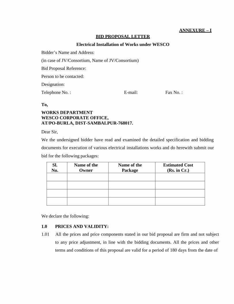
BID PROPOSAL LETTER
Electrical Installation of Works under WESCO
ANNEXURE – I
Bidder‟s Name and Address:
(in case of JV/Consortium, Name of JV/Consortium)
Bid Proposal Reference:
Person to be contacted:
Designation:
Telephone No. : E-mail: Fax No. :
To,
WORKS DEPARTMENT
WESCO CORPORATE OFFICE,
AT/PO-BURLA, DIST-SAMBALPUR-768017.
Dear Sir,
We the undersigned bidder have read and examined the detailed specification and bidding
documents for execution of various electrical installations works and do herewith submit our
bid for the following packages:
Sl.
No.
Name of the
Owner
Name of the
Package
Estimated Cost
(Rs. in Cr.)
We declare the following:
1.0 PRICES AND VALIDITY:
1.01 All the prices and price components stated in our bid proposal are firm and not subject
to any price adjustment, in line with the bidding documents. All the prices and other
terms and conditions of this proposal are valid for a period of 180 days from the date of
Page 31
opening of the bids. We further declare that prices stated in our proposal are in
accordance with “Instructions to Bidders” of bidding documents.
1.02 We do hereby confirm that our bid prices as quoted in attached Schedules include all
import duties and levies including license fees lawfully payable by us on imported items
and other taxes, duties and levies applicable on bought – out components, materials,
equipment and other items and confirm that any such taxes, duties and levies
additionally payable shall be to our account.
1.03 We confirm that the Sales tax on Works Contract, Turnover Tax or any other similar
taxes under the Sales Tax Act, as applicable, are included in our quoted bid price and
there shall not be any liability on this account to the Purchasers. We understand that
Owner shall, deduct such taxes at source as per the rules and issue TDS Certificate to
us.
1.04 We confirm that, in our Bid Price, we have considered service tax in line with lawful
prevalent practice.
1.05 Price components of various items are indicated in the B.O.Q. for the respective works.
1.06 We further declare that while quoting the price, the due credit under MODVAT scheme,
re-christened as CENVAT scheme, as per relevant Government policies wherever
applicable, have been taken into account.
1.07 We, having studied the bidding document in three volumes relating to taxes & duties
and hereby, declare that if any income tax, charge on income tax or any other corporate
tax is attracted under the law, we agree to pay the same.
1.08 We are aware that the Price schedules do not generally give a full description of the
supplies to be made and work to be performed under each item and we shall be deemed
to have read the Technical Specifications and other bidding documents and drawings to
ascertain the full scope of work included in each item while filling in the related and
prices. We agree that the entered rates and prices shall be deemed to include the full
scope as aforesaid, including overheads and profits.
Page 32
1.09 We understand that in the price schedule, if there is discrepancy between the unit price
and total price, the same shall be corrected as per relevant provisions.
1.10 We declare that prices for items left blank in the schedules will be deemed to have been
included in other items. The TOTAL for each schedule and the TOTAL of Grand
summary shall be deemed to be the total price for executing the facilities and sections
thereof in complete accordance with the contract, whether or not each item has been
priced.
2.0 CONSTRUCTION OF THE CONTRACT
2.01 We declare that we are making the offer on the basis of indivisible supply-cum-
Erection contract on a single source responsibility basis.
3.0 BID SECURITY (EMD)
We are enclosing Bank Draft / Bank Guarantee No. dtd. amounting to
Rs.--------------------- (Rupees only) issued by
Bank ---------------------------branch, payable on Burla towards Bid Security against our
above Bid. The Bid Security amount has been computed by adding the Estimated Cost
of the work .
4.0 EQUIPMENT PERFORMANCE GURANTEE
We declare that the ratings and performance figures of the equipment to be furnished
and erected by us are guaranteed. The Guaranteed particulars of different equipments
are enclosed along with our bid.
5.0 BID PRICING
We further declare that the prices stated in our proposal are in accordance with your
„Instruction of Bidders of Conditions of Contract, Volume-1 of the bid documents.
6.0 PRICE ADJUSTMENT
We declare that all the prices and price components stated in our offer are on FIRM
price basis.
Page 33
7.0 QUALIFICATION
We confirm having submitted the Qualification Data in original plus one copy, as
required by you under clause 6.0 „Invitation for Bids‟. Further we have filled in the
information for qualification requirements. In case you require any further
information in this regard, we agree to furnished the same in time .
8.0 DEVIATIONS
8.01 We declare that the contract shall be executed strictly in accordance with the
specifications and documents except for the variations and deviations all of which
have been detailed out exhaustively in the following schedules, irrespective of
whatever has been stated to the contrary anywhere else in our proposal.
a) Commercial Deviations Schedule
b) Cost of withdrawal of Deviations on Critical
c) Technical Deviation Schedule
8.02 We confirm that specified stipulation of following critical clauses is acceptable to us
and no deviations/exceptions are taken on any account whatsoever in the following
clauses:
(a) Payment Terms :
(b) Bid Guarantee :
(c) Contract Performance Guarantee :
(d) Liquidated Damages for delay :
(e) Prices and Price Adjustment :
(f) Guarantee / Warrantees :
8.03 Further, we agree that the additional conditions, deviations, if any, found in our bid
proposal documents other than those stated in attached Deviation Schedules, save that
pertaining to any rebates offered, shall not be given effect to.
9.0 ADDITIONAL INFORMATION
We have included with this proposal additional information listed. We further confirm
that such additional information does not imply any additional deviation beyond those
covered in appropriate schedules and in case of any contradiction between these
additional information and other provisions of Bid, the latter prevail.
Page 34
10.0 GURANTEE DECLARATION
We guarantee that the equipment offered shall meet the rating and performance
requirements stipulated in this specification. The Guarantee Declaration which shall
attract levy of liquidated damages for non-performance is indicated in the relevant
schedule.
11.0 BOUGHT-OUT AND SUB-CONTRACTED ITEM
We are furnishing herewith at appropriate Schedule, the detail of all major item of
supply amounting to more than 10% of our Bid Price, which were propose subletting
giving detail of the name of sub-contractor/sub-vendor and quantity for each item.
12.0 WORK SCHEDULE
If this proposal is accepted by you, we agree to submit engineering data, provide
services and complete the entire work from time to time, in accordance with schedule
indicated in the proposal. We fully understand that the time schedule stipulated in this
proposal is the essence of the contract, if awarded. The completion schedule of the
various major key phases of the work is indicated in the designated schedule.
13.0 CONTRACT PERFORMANCE GUARANTEE
We further agree that if our Bid is accepted we shall provide an irrevocable Bank
guarantee towards Contract Performance Guarantee, of value equivalent to ten percent
(10%) of the Contract Price initially valid up to the end of ninety (90) days after the end
of the contract warranty period in the form of Bank Guarantee in your favour within 15
(fifteen) days from the date of „Notice of Award of Contract‟ and enter into a formal
agreement with you immediately thereafter.
Dated this ………………………..day of ………………………………20…..
Thanking you,
Yours faithfully,
(Signature of the Authorized Signatory)
Page 35
Name ……………………………
Designation ……………………………..
Seal of the company………..
Date : ………………………….
Place :
(Written power of Attorney of all signatories of the bid to commit the Bidder must be
enclosed with the Bid. In case of joint venture, the written Power of Attorney of all
signatories from respective partners must be enclosed with the Bid. .
*** Applicable case of a Bid from Joint Venture of Firms. Further, the Bid must be
signed by each partner of the Joint venture.
Page 36
ANNEXURE – II
To,
WORKS DEPARTMENT
WESCO CORPORATE OFFICE,
AT/PO-BURLA, DIST-SAMBALPUR-768017.
Sir,
Having examined the above specifications together with the Tender terms and conditions
referred to therein
1 – I / We the undersigned do hereby offer to execute the contract covered there on in complete
shape in all respects as per the rules entered in the attached contract schedule of prices in the
tender.
2 – I / We do hereby under take to have executed the contract within the time specified in the
tender.
3 – I / We do hereby guarantee the technical particulars given in the tender supported with
necessary reports from concerned authorities.
4 – I / We do hereby certify to have purchased a copy of the tender specifications by remitting
Cash / Demand draft & this has been duly acknowledged by you in your letter
No…………Dt…………
5 – I / We do hereby agree to furnish the composite Bank Guarantee in the manner specified /
acceptable by WESCO (as the case may be) & for the sum as applicable to me / us as per clause
No.13 of Annexure -V of this specification within fifteen days of issue of Letter of intent /
Work Order , in the event of Work order being decided in my / us favour , failing which I / We
clearly understand that the said LOI / W.O. shall be liable to be withdrawn by the Owner.
Signed this…………….Day of……………………20…
Yours faithfully
(Signature of Bidder with Seal of Company)
Page 37
ANNEXURE – III
PROFORMA FOR CONTRACT PERFORMANCE BANK GUARANTEE
(To be executed on Rs. 100/- Non-judicial Stamp Paper purchased in the name of the BG
Issuing Bank)
This Guarantee Bond is executed this day of
by us,
Bank at
P.O. P.S. Dist State
Whereas Western Electricity Supply Company of Odisha Ltd.(WESCO) , Corporate Office, At/Po-Burla,
Sambalpur-768017 registered under the Company Act 1956 (here in after
called “Owner”) has placed Work Order No.
Dt.
(hereinafter called
“Agreement”) with M/s (hereinafter called
“the Contractor”) for supply and installation of (description of the works)
and whereas Owner has agreed (1) to exempt the Contractor from making payment of security
deposit, (2) to release 100% payment of the cost of materials as per the said agreement and (3)
to exempt from performance guarantee on furnishing by the Contractor to Owner a composite
Bank Guarantee of the value of 10% (ten percent) of the Contract price of the said Agreement.
1. Now, therefore, in consideration of Owner having agreed (1) to exempt the Contractor
for making payment of security deposit, (2) to release 100% payment to the Contractor and (3)
to exempt from furnishing performance guarantee in terms of the said Agreement as aforesaid,
we the
Bank, Address (code No.
) (hereinafter referred to as “the Bank”) do hereby undertake to pay to the Owner an
amount not exceeding Rs.
(Rupees )
Page 38
only against any loss or damage caused to or suffered by the Owner by reason of any breach by
the said Contractor(s) of any of the terms or conditions contained in the said Agreement.
2. We, the Bank do hereby undertake to pay the amounts due
and payable under the guarantee without any demur, merely on a demand from Owner stating
that the amount claimed is due by way of loss or damage caused to or suffered by Owner by
reason of any breach by the said Contractor(s) of any of the terms or conditions contained in
the said Agreement or by the reason of any breach by the said Contractor‟s failure to perform
the said Agreement. Any such demand made on the Bank shall be conclusive as regards the
amount due and payable by the Bank under this Guarantee. However, our liability under this
guarantee shall be restricted to an amount not exceeding Rs.
) only.
(Rupees
3. We, the Bank also undertake to pay to Owner any money
so demanded not withstanding any dispute or dispute raised by the Contractor(s) in any suit or
proceeding instituted/ pending before any court or Tribunal relating thereto our liability under
this Agreement being absolute and irrevocable. The payment so made by us under this bond
shall be valid discharge of our liability for payment there under and the Contractor(s) shall have
no claim against us for making such payment.
4. We, the Bank further agree that the guarantee herein
Page 39
contain shall remain in full force and effect during the period that would be taken for the
performance of the said Agreement and it shall continue to remain in force endorsable till all
the dues of Owner under by virtue of the said Agreement have been fully paid and its claim
satisfied or discharged or till Purchaser certifies that the terms and conditions of the said
Agreement have been fully and properly carried out by the said Contractor(s) and accordingly
discharge this guarantee and will not be revoked by us during the validity of the guarantee
period.
Unless a demand or claim under this guarantee is made on us or with our
Burla/Sambalpur branch at (Name, address of the
Burla/Sambalpur branch and code No.) in writing on or before
(date) we shall be discharged from all liability under this guarantee thereafter.
5. We, the Bank further agree that Owner shall have the
fullest liberty without our consent and without affecting in any manner our obligations
hereunder to vary any of the terms and conditions of the said Agreement or to extend time of
performance by the said Contractor(s) and we shall not be relieved from our liability by reason
of any such variation or extension being granted to the said Contractor(s) or for any
forbearance act or omission on part of Owner or any indulgence by Owner to the said
Contractor(s) or by any such matter or thing whatsoever which under the law relating to
sureties would but for this provisions have effect of so relieving us.
6. The Guarantee will not be discharged due to change in the name, style and constitution
of the Bank and or Contractor(s).
7. We, the Bank lastly undertake not to revoke this
Guarantee during its currency except with the previous consent of the Owner in writing.
Dated the day of Two thousand .
Not withstanding anything contained herein above.
Our liability under this Bank Guarantee shall not exceed Rs. (Rupees
) only.
Page 40
The Bank Guarantee shall be valid up to only.
Our ………………………. branch at Burla/Sambalpur (Name & Address of the
Burla/Sambalpur branch) is liable to pay the guaranteed amount depending on the filing of
claim and any part thereof under this Bank Guarantee only and only if you serve upon us at
our
branch a written claim or demand and received by us at our Bhubaneswar branch on or before
Dt.
thereafter.
otherwise bank shall be discharged of all liabilities under this guarantee
For
N.B.:
(1) Name of the Contractor:
(2) No. & date of the Work order/ agreement:
(3) Amount of W.O:
(4) Name of Work:
(5) Name of the Bank:
(6) Amount of the Bank Guarantee:
(Indicate the name of the Bank)
(7) Name, Address and Code No. of the Burla/Sambalpur Branch of the Issuing
Bank: (8) Validity period or date up to which the agreement is valid:
(9) Signature of the Constituent Authority of the Bank with seal:
(10) Name & addresses of the Witnesses with signature:
(11) The Bank Guarantee shall be accepted only after getting confirmation from the
issuing Branch & from main branch/specified branch at Burla/Sambalpur of issuing
Bank.
Page 41
ANNEXURE – IV
PROFORMA OF BANK GUARANTEE FOR ADVANCE PAYMENT
(To be stamped in accordance with Stamp Act)
(To be executed on Rs. 100/- Non-judicial Stamp Paper purchased in the name of the BG
Issuing Bank)
Ref............................ Bank Guarantee No.................
Date ............................
To,
The Managing Director,
WESCO, Burla
Dear Sir,
In consideration of whereas Western Electricity Supply Company of Orissa Ltd. (WESCO)
(hereinafter referred to as the „Owner‟, which expression shall, unless repugnant to the context
or meaning thereof include its successors, administrators and assigns) having awarded to
M/s.................. (hereinafter referred to as the "Contractor” which expression shall unless
repugnant to the context or meaning thereof, include its successors, administrators, executors
and assigns), a Contract by issue of Owner‟s Letter of Award No.................. dated ...................
and the same having been acknowledged by the Contractor, resulting in a Contract bearing
No....................... dated .................. valued at ...................... for
.................................................................. (Scope of work)................................... (Hereinafter
called the 'Contract‟) and the Owner having agreed to make an advance payment to the
Contractor for performance of the above Contract amounting................................. (in words
and figures ) as an advance against Bank Guarantee to be furnished by the Contractor.
We,................................................................................................................. (Name of the Bank)
having its Head Office at .............................. (hereinafter referred to as the „Bank‟, which
expression shall, unless repugnant to the context or meaning thereof , include its successors,
administrators, executors and assigns ) do hereby guarantee and undertake to pay the Owner,
immediately on demand any or, all monies payable by the Contractor to the extent of
..................................... as aforesaid at any time up to ........ @ ............... without any demur,
reservation, contest, recourse or protest and / or without any reference to the Contractor. Any
Page 42
such demand made by the Owner on the Bank shall be conclusive and binding notwithstanding
any difference between the Purchaser and the Contractor or any dispute pending before any
Court, Tribunal, Arbitrator or any other authority. We agree that the guarantee herein contained
shall be irrevocable and shall continue to be enforceable till the Owner discharges this guarantee.
The Owner shall have the fullest liberty without affecting in any way the liability of the Bank
under this guarantee, from time to time to vary the advance or to extend the time for
performance of the Contract by the Contractor. The Owner shall have the fullest liberty without
affecting this guarantee, to postpone from time to time the exercise of any powers vested in
them or of any right which they might have against the Contractor, and to exercise the same at
any time in any manner, and either to enforce or to forbear to enforce any covenants, contained
or implied, in the Contract between the Owner and the Contractor or any other course or remedy
or security available to the Owner. The Bank shall not be released of its obligations under these
presents by an exercise by the Owner of its liberty with reference to the matters aforesaid or any
of them or by reason of any other act or forbearance or other acts of omission or commission on
the part of the Owner or any other indulgence shown by the Owner or by another matter or thing,
whatsoever, which under law would, but for this provision have the effect of relieving the
Bank.
Bank also agrees that the Owner at its option shall be entitled to enforce this Guarantee against
the Bank as a principal debtor, in the first instance without proceeding against the Contractor
and notwithstanding any security or other guarantee that the Owner may have in relation to the
Contractor'‟ liabilities.
Notwithstanding anything contained hereinabove our liability under this guarantee is limited to
.................. and it shall remain in force up to and including ...........@ ........... and shall be
extended from time to time for such period (not exceeding one year ), as may be desired by
M/s. ........................ on whose behalf this guarantee has been given.
The Guarantee will not be discharged due to change in the name, style and constitution of the
Bank and or Contractor(s).
All other contentions in B.G will safe guard the interest of Owner.
We, the Bank lastly undertake not to revoke this Guarantee
Page 43
during its currency except with the previous consent of Owner in writing.
Dated ____the day of Two thousand .
Notwithstanding anything contained herein above.
Our liability under this Bank Guarantee shall not exceed Rs. (Rupees
)
only.
The Bank Guarantee shall be valid up to only.
Our ………………………. branch at Burla/Sambalpur (Name & Address of the
Burla/Sambalpur branch) is liable to pay the guaranteed amount depending on the filing of
claim and any part thereof under this Bank Guarantee only and only if you serve upon us
at our Burla/Sambalpur branch a written claim or demand and received by us at our
Burla/Sambalpur branch on or before Dt.____ otherwise bank shall be discharged of all
liabilities under this guarantee thereafter
For _____ (indicate the name of the Bank )
Dated this .............. Day of .........20......... at .........................................
WITNESS
........................................................
.............................................................................
.. (Signature) (Signature)
.........................................................
............................................................................... (Name) (Name)
..........................................................
............................................................................... (Official
Address(Designation with Bank Stamp)
Attorney as per
Power of Attorney
No................... Dated
...........................................
@ This date shall be ninety (90) days after the schedule date of completion of the
contract,
Page 44
ANNEXURE – V (A)
LETTER OF COMPLIANCE OF QUALIFYING REQUIREMENT
(In case of Bidder being a Single Firm)
To,
WORKS DEPARTMENT
WESCO CORPORATE OFFICE,
AT/PO-BURLA, DIST-SAMBALPUR-768017.
Dear Sirs,
I/We ……………. (Name of Bidder) are submitting the bid as a single firm. In support of our
meeting the Qualifying requirements (QR) for bidders, stipulated in this tender specification,
we furnish herewith the details/documents etc. as follows.
Table – A: Previous Works Experience:
Package
Quoted
for
Description
of Proposed
Works
Tender
Qty
Qty Installed & Commissioned
Sl.
No.
FY
Name
of
Client
WO Ref
Qty
Installed
Documents
provided in
proof of having
executed the
works during
the relevant FY.
Table – B: Average Annual Turnover:
Package Quoted for
Estimated
Cost of the
Package
(Rs. in Lakh)
Annual Turnover Data
(Rs. in Lakh)
Financial Year
Turnover
(Rs. in Lakh)
Last Three Year preceding to
the year of tender
Total Estimated Cost of
the packages quoted for
Average Turnover
Page 45
Note: Continuation sheets, of like size and format, may be used as per Bidder‟s requirements and
annexed to this Schedule.
I/We declare that we are fulfilling the qualifying requirements as per clause no. 2.0 of Section –
I, Invitation for Bids (IFB).
For & on behalf of ………… (Name of the Bidder).
Page 46
ANNEXURE – V (B)
LETTER OF COMPLIANCE OF QUALIFYING REQUIREMENT
(In case of Bidder being a Joint Venture / Consortium Firm)
To,
WORKS DEPARTMENT
WESCO CORPORATE OFFICE,
AT/PO-BURLA, DIST-SAMBALPUR-768017.
Dear Sirs,
I/We ……………. (Name of Bidder) are submitting the bid as a single firm. In support of our
meeting the Qualifying requirements (QR) for bidders, stipulated in this tender specification,
we furnish herewith the details/documents etc. as follows.
Name of the members of the JV / Consortium
1.
2.
3.
Table – A: Previous Works Experience: Name of the Member (any one member only)
Package
Quoted
for
Description
of Proposed
Works
Tender
Qty
Qty Installed & Commissioned
Sl.
No.
FY
Name
of
Client
WO Ref
Qty
Installed
Documents
provided in
proof of
having
executed the
works during
the relevant
FY.
Page 47
Table – B: Average Annual Turnover:
Package Quoted
for
Estima
ted
Cost of
the
Packag
e
(Rs. in
Lakh)
Annual Turnover
(Rs. in Lakh)
Financial
Year
(only best
three fin.
Years)
Turnov er
(Rs. in
Lakh)
FY 2009 -10
FY 2010-11
FY 2011 -12
FY 2012-13
FY 2013 – 14
Total
Total Estimated
Cost of the
packages quoted
for
Note: Continuation sheets, of like size and format, may be used as per Bidder‟s requirements
and annexed to this Schedule.
I/We declare that we are fulfilling the qualifying requirements as per clause no. 2.0 of Section –
I, Invitation for Bids (IFB).
For & on behalf of ………… (Name of the
Bidder).
Date: (Signature) …………………..
Place: (Printed Name) ……………….
(Designation) …………………..
(Common Seal) …………………
Page 48
Note: 1. Continuation sheets, of like size and format, may be used as per Bidder‟s
requirements and annexed to this Schedule.
2. In case of Joint Venture, separate sheet for each partner of Joint Venture
should be used.
Date: (Signature) …………………..
Place: (Printed Name) ……………….
(Designation) …………………..
(Common Seal) …………………
Page 49
ANNEXURE – VI
DETAILS OF COMMERCIAL DEVIATIONS
Bidder‟s Name & Address
To,
WORKS DEPARTMENT
WESCO CORPORATE OFFICE,
AT/PO-BURLA, DIST-SAMBALPUR-768017.
Dear Sirs,
Sub: Commercial Deviation for Construction of Name of the project.
The following are the Commercial Deviations and variations from and exceptions to the
specifications and documents for the subject Project. These deviations and variations are
exhaustive. Except for these deviations, the entire work shall be performed as per your
specifications and documents
Volume/Clause
Ref./Page
No.
As specified in the
Specification
Commercial deviation and variation
to the specification
Date: (Signature) …………………..
Place: (Printed Name) ……………….
(Designation) …………………..
(Common Seal) …………………
Note: 1. Continuation sheets, of like size and format, may be used as per Bidder‟s
requirements and annexed to this Schedule.
2. This will be read out during opening of Part-I Bid.
Page 50
ANNEXURE –VI
DETAILS TECHNICAL DEVIATIONS
Bidder‟s Name & Address
To,
WORKS DEPARTMENT
WESCO CORPORATE OFFICE,
AT/PO-BURLA, DIST-SAMBALPUR-768017.
Dear Sirs,
Sub: Technical Deviation for Construction of ………………. (Name of the Project)
The following are the Technical Deviations and variations from and exceptions to the
specifications and documents for the subject package. These deviations and variations are
exhaustive. Except for these deviations, the entire work shall be performed as per your
specifications and documents
Volume/Clause
Ref./Page No.
As specified in the
Specification / Relevant
ISS
Technical deviation and
variation to the
specification
Date: (Signature) …………………..
Place: (Printed Name) ……………….
(Designation) …………………..
(Common Seal) …………………
Note: 1. Continuation sheets, of like size and format, may be used as per Bidder‟s
requirements and annexed to this Schedule.
2. The deviations and variations, if any, shall be brought out separately for each of the
equipment.
Page 51
ADDITIONAL INFORMATION
Bidder‟s Name & Address
To,
WORKS DEPARTMENT, WESCO CORPORATE OFFICE, AT/PO-BURLA, DIST-SAMBALPUR-768017.
Dear Sirs,
ANNEXURE–VII
We have enclosed with our proposal the following additional information for the subject,
package.
Sl. No Brief description of Information Ref.& Page No.
Date: (Signature) …………………..
Place: (Printed Name) ……………….
(Designation) …………………..
(Common Seal) …………………
Note: Continuation sheets, of like size and format, may be used as per Bidder‟s requirements
and annexed to this Schedule.
Page 52
ANNEXURE –VIII
BOUGHT OUT & SUB CONTRACTED ITEMS
Bidder‟s Name & Address
To,
WORKS DEPARTMENT
WESCO CORPORATE OFFICE,
AT/PO-BURLA, DIST-SAMBALPUR-768017.
Dear Sirs,
We hereby furnish the details of the items/sub-assemblies amounting to more than 10% of our
bid price, we propose to buy for the purpose of subject package
Sl. No Item description Qty. Proposed Source of Supply
Be bought/
Sub-contracted
1. …………………… ………………………….. …………………………..
2. ……………………. ……………………………. …………………………..
3. …………………….. ……………………………. ……………………………
4…………………….. ……………………………. …………………………….
5. ……………………. …………………………….. …………………………….
6. …………………… …………………………….. …………………………….
7. …………………… …………………………….. …………………………….
Date:
(Signature) …………………..
Place: ( Printed Name) ……………….
(Designation) …………………..
(Common Seal)
Page 53
ANNEXURE – IX
WORK COMPLETION SCHEDULE
Bidder‟s Name & Address
To,
WORKS DEPARTMENT
WESCO CORPORATE OFFICE,
AT/PO-BURLA, DIST-SAMBALPUR-768017.
Dear Sirs,
We hereby declare that the following Work Completion Schedule shall be followed by us for
the purpose of subject package
Sl. No Description of Work Period in Months( from the date of LOA)
1 Completion of detailed engineering
2 Procurement of raw materials
3 Establishment of site offices
4 Erection
(a) Commencement
(b) Completion
5 Testing & Pre-commissioning
(a) Commencement
(b) Completion
6 Commissioning
Date: (Signature) …………………..
Place: (Printed Name) ……………….
(Designation) …………………..
(Common Seal) ………………..
Page 54
CHECK LIST
Bidder‟s Name & Address
To,
WORKS DEPARTMENT WESCO CORPORATE, AT/PO-BURLA, DIST-SAMBALPUR-768017.
Dear Sirs,
ANNEXURE – XIII
Sl.
No.
Item Description Status of the
Submission
of data
Remarks
1 2 3 4
1. Bid Guarantee Yes /No If yes please give details No, amount,
validity & date of issue.
2. Qualifying Data Yes /No
3. Commercial Deviation Yes /No
4. Technical Deviation Yes /No
5. Cost of withdrawn of
deviations
Yes /No
6. Bid validity Yes /No If yes state here the period.
7. Period of completion Yes/No If, yes please state here the period of
completion.
8. Additional information
offered by bidder
State here briefly
N.B.:- The contents of this schedule will be read out during opening of Part-I Bid.
………………………
Signature of Bidder
Date & Seal:
Page 55
Page 2 of 2
N.B:-
1. The bid guarantee one original and one copy shall be furnished in two separate
sealed envelopes appropriately superscribed thereon.
2. All Schedules pertaining to prices (originals) shall be furnished in a sealed envelope
duly superscribed thereon. Similarly one set of copies of such schedules shall be
given in a separate sealed envelope (these are not to be opened during opening of
Part –I ).
3. All other schedules, one set original and another copy shall be submitted in two
separate sealed envelope (these are to be opened during Part –I bid opening )
Date: (Signature) …………………..
Place: (Printed Name) ……………….
(Designation) …………………..
(Common Seal) ………………..
Page 56
ANNEXURE-XI
SELF DECLARATION FORM
Name of the Owner/Purchaser: ---------------
Sir,
Tender Notice No: ----------------------------- 1. I / we, the undersigned do hereby declare that, I / we have never ever been blacklisted and
/ or there were no debarring actions against us for any default in supply of material /
equipments or in the performance of the contract entrusted to us in any of the Electricity
Utilities of India.
2. In the event of any such information pertaining to the aforesaid matter found at any
given point of time either during the course of the contract or at the bidding stage, my
bid/contract shall be liable for truncation / cancellation / termination without any notice at
the sole discretion of the owner/purchaser.
Place- Date-
Yours faithfully,
Signature of the bidder With seal
(This form shall be duly filled-up and signed by the bidder & submitted along with the original copy of the Bid.)
Page 57
ANNEXURE – XI (A)
PROFORMA FOR BANK GUARANTEE FOR EARNEST MONEY DEPOSIT
(ON NON-JUDICIAL STAMP PAPER OF Rs.100/-)
Ref Date Bank Guarantee No:
In accordance with invitation to Tender Notice No.--------- Dated ------------- of Western
Electricity Supply Company of Orissa Ltd. [herein after referred to as the WESCO] for the execution of
(name of package)
M/s Address wish/wished to participate in the said
tender and as the Bank Guarantee for the sum of Rs.
[Rupees
words) is required to be submitted by the Bidder.
1.We the
Valid for a period of ………… days (in
[Indicate the Name of the Bank]
[Hereinafter referred to as „the Bank‟] at the request of M/S
[Herein after referred to as
supplier (s)] do hereby unequivocally and unconditionally guarantee and undertake to pay during the
above said period, on written request by WESCO an amount not exceeding Rs. to
the WESCO, without any reservation. The guarantee would remain valid up to 4.00 PM of
[date] and if any further extension to this is required, the same will be extended
on receiving instructions from M/s
this guarantee has been issued.
on whose behalf
2. We the [Indicate the name of the bank] do hereby
further undertake to pay the amounts due and payable under this guarantee without any demur, merely
on a demand from the WESCO stating that the amount claimed is due by way of loss or damage caused
to or would be caused to or suffered by the WESCO by reason of any breach by the said supplier [s] of
any of the terms or conditions or failure to perform the said Bid. Any such demand made on the Bank
shall be conclusive as regards the amount due and payable by the Bank under this guarantee. However,
our liability under this guarantee shall be restricted to an amount not exceeding
Rs. (in wards)
3. We, the Bank undertake to pay the WESCO any money so demanded not
withstanding any dispute or disputes so raised by the supplier [s] in any suit or proceeding
instituted/pending before any Court or Tribunal relating thereto, our liability under this agreement being
absolute and unequivocal. The payment so made by us under this bond shall be a valid discharge of our
liability for payment there under and the supplier(s) shall have no claim against us for making such
payment.
Page 58
4. We, the Bank [Indicate the name of the bank] or our local branch at Bhubaneswar further
agree that the guarantee herein contain shall remain in full force and effect during the aforesaid period of --
------------ days and it shall continue to be so enforceable till all the dues of the WESCO under by virtue of
the said Bid have been fully paid and its claims satisfied or discharged or till WESCO certifies that the
terms and conditions of the said Bid have been fully and properly carried out by the said Supplier [s] and
accordingly discharges this guarantee. Unless a demand or claim under this guarantee is made on us in
writing on or before the (date) we shall be discharged from all liability under this
guarantee thereafter.
5. We, the Bank [Indicate the name of the bank] or our local branch at Bhubaneswar further
agree that the WESCO shall have the fullest liberty without our consent and without affecting in any
manner our obligations here under to vary any of the terms and conditions of the said Bid or to extend time
of performance by the said Supplier [s] from time to time or to postpone for any time or from time to time
any of the powers exercisable by the WESCO against the said supplier [s] and to forbear or enforce any of
the terms and conditions relating to the said bid and we shall not be relieved from our liability by reason of
any such variation, postponement or extension being granted to the said Supplier [s] or for any forbearance
act or omission on the part of the WESCO or any indulgence by the WESCO to the said Supplier[s] or by
any such matter or thing whatsoever which under the law relating to sureties would but for this provision,
have effect of so relieving us.
6. This guarantee will not be discharged due to the change in the name, style and constitution of the Bank
or the supplier [s].
7. We, the _Bank or our local branch at Burla/Sambalpur lastly undertake not revoke
this Guarantee during its currency except with the previous consent of the WESCO in writing.
8. We, the Bank further agree that this guarantee shall also be invokable at
our place of business at Burla/Sambalpur [Indicate address & Branch code of local branch at
Burla/Sambalpur] in the State of Orissa.
Dated Day of 2013.
Witness ((Signature, names & address) For [Indicate the name of Bank]
1. Power of Attorney No.
2 Date:
SEAL OF BANK
Note: The non-judicial stamp paper of worth Rs.100/- shall be purchased in the name of the
bank, which has issued the bank guarantee.
Page 59
ANNEXURE- XI (B)
FORM OF EXTENSION OF BANK GUARANTEE (ON NON-JUDICIAL STAMP PAPER OF Rs.100/-)
Ref. No.
Dated:
WESCO Ltd.,
Corporate Office: At/Po- Burla,
Sambalpur-768017.
Dear Sirs,
Sub: Extension of Bank Guarantee No. for Rs. favouring yourselves
expiring
on account of M/s.
in respect of contract
No. dated (hereinafter called original bank guarantee).
At the request of M/s. we bank Branch office at having its
head office at do hereby extend our liability under the above mentioned guarantee No.
Dated
for a further period of
Years/months from to
expire on except as provided above, all other terms and conditions of the original bank
guarantee No. _dated shall remain unaltered and binding.
Please treat this as an integral part of the original guarantee to which it would be attached.
Yours faithfully,
For
Manager/Agent/Accountant
Power of Attorney No.
Date:
SEAL OF BANK
Note: The non-judicial stamp paper of worth Rs.100/- shall be purchased in the name of the bank,
which has issued the bank guarantee
Page 60
ANNEXURE – XII
FORM OF POWER OF ATTORNEY FOR JOINT VENTURE
(On Non –Judicial Stamp Paper of Appropriate value
to be Purchased in the Name of Joint Venture)
KNOW ALL MEN BY THESE PRESENTS THAT WE, the Members whose details are given
hereunder…………………………….. have formed a joint Venture/Consortium and having our
Registered Office (s)/Head Office (s) at ……………………………….(hereinafter called the
‗Joint Venture/Consortium„ which expression shall unless repugnant to the context or meaning
thereof, include its successors, administrators and assigns) do hereby constitute, nominate and
appoint M/s……………………………………………. a company/Electrical Contractor
incorporated under the laws of …………..and having its Registered/Head Office at
…………….as our duly constituted lawful Attorney (hereinafter called ―Attorney‖ (hereinafter
called Lead Member) to exercise all or any of the powers for and on behalf of the joint
venture/Consortium in regard to Tender Notice No…………….. for construction of
……………. (name of the package) of WESCO (hereinafter called the ―Owner‖) for which bids
have been invited by the Owner, to undertake the following acts :
(i) To submit proposal, participate and negotiate in respect of the aforesaid Bid –
Specification of the Owner on behalf of the ―Joint Venture / Consortium‖.
(ii) To negotiate with Owner the terms and conditions for award of the contract pursuant to
the aforesaid Bid and to sign the contract with the Owner for and on behalf of the ―Joint
Venture / Consortium‖.
(iii) To do any other act or submit any document related to the above.
(iv) To receive, accept and execute the contract for and on behalf of the ―Joint Venture /
Consortium‖.
(v) To submit the Contract performance security in the form of an unconditional
irrecoverable Bank Guarantee in the prescribed format and as per terms of the contract.
It is clearly understood that the Lead Member shall ensure performance of the contracts(s) and
if one or more Member fail to perform their respective portion of the contracts(s), the same
shall be deemed to be a default by all the Members.
Page 61
It is expressly understood that this power of Attorney shall remain valid, binding and
irrevocable till completion of the Defect of liability period in terms of the contract.
The Joint Venture / Consortium hereby agrees and undertakes to ratify and confirm all the
whatsoever the said Lead Member quotes in the bid, negotiates and signs the Contract with the
Owner and / or proposes to act on behalf of the Joint Venture / Consortium by virtue of this
Power of Attorney and the same shall bind the Joint Venture / Consortium as if done by itself.
IN WITNESS THEREOF the Members Constituting the Joint Venture / Consortium as
aforesaid have executed these presents on this ………… day of …….. under the Common Seal
(s) of their Companies
for and on behalf of
the embers of Joint Ventures/Consortium
…………………………………
…………………………………
…………………………………
The Common Seal of the above Partners of the Joint Venture / Consortium:
The Common Seal has been affixed there unto in the presence of:
WITNESS
1. Signature …………………………………
Name …………………………………
Designation …………………………………
Occupation …………………………………
2. Signature …………………………………...
Name ……………………………………….
Designation …………………………………
Occupation …………………………………
Page 62
ANNEXURE – XIII
FORM OF JOINT VENTURE/ CONSORTIUM
AGREEMENT
(To be executed on non-judicial stamp paper of appropriate value to be purchased in
the name of executants or as required by the Jurisdiction in which executed)
THIS Joint Venture/Consortium Agreement executed on this ……….. day of
…………… Two thousand …………………… by:
M/s. …………….…………….a company/Partnership Firm/Sole Proprietorship
Organization incorporated under the …………….……………. Act/Laws and having its
Registered Office/Head Office at ……………. …………….……………. …………….
(hereinafter called the "Lead Member/First Member" which expression shall include its
successors),and
M/s. …………….…………….a company/Partnership Firm/Sole Proprietorship
Organization incorporated under the …………….……………. Act/Laws and having its
Registered Office/Head Office at ……………. …………….……………. …………….
(hereinafter called the " Second Member" which expression shall include its
successors),and
M/s. …………….…………….a company/Partnership Firm/Sole Proprietorship
Organization incorporated under the …………….……………. Act/Laws and having its
Registered Office/Head Office at ……………. …………….……………. …………….
(hereinafter called the "Third Member" which expression shall include its
successors),and
M/s. …………….…………….a company/Partnership Firm/Sole Proprietorship
Organization incorporated under the …………….……………. Act/Laws and having its
Registered Office/Head Office at ……………. …………….……………. …………….
(hereinafter called the "Fourth Member" which expression shall include its successors).
The Lead Member/First Member, Second Member, the Third Member and the Fourth
Member shall collectively hereinafter be called as the ―Joint venture/Consortium
Page 63
Members‖ for the purpose of submitting a bid proposal to Western Electricity Supply
Company of Orissa Ltd. (hereinafter referred to as WESCO) being a company
incorporated under the Companies Act.
1956 having its. Registered Office at N 1/22, IRC Village, Bhubaneswar - 15
(hereinafter
called the ―Owner‖) in response to the invitation of bids (hereinafter called as ―Tender
Notice
No…………….‖ Document) dated…………….. for supply, erection, Testing &
Commissioning as per the scope of work ……………….(hereinafter called
as ―the Transaction‖)
WHEREAS Clause-2 of the Invitation for Bids (IFB), stipulates that Two or more
bidder(s) may form a joint venture/Consortium among themselves and apply against this
tender specification, provided they fulfill the following eligible criteria;
1. They should have legally valid Consortium agreement as per the prescribed
format for the purpose of participation in the bidding process. The total no of a
Consortium shall be limited to four members.
2. One of the Joint Venture/Consortium members should be a Electrical Contractor
having valid HT License.
3. Consortium as a whole shall meet the qualifying norms specified in the tender,
they participate.
4. The lead member of the Consortium should meet at least 50% of the qualifying
norms in respect to the work experience & Turn Over requirement.
5. Besides the lead member, other member(s) of the Consortium together shall
meet the balance 50% of the qualifying norms in respect to the work
experience & Turn Over requirement.
6. All the Consortium member(s) shall authorize the lead partner by submitting a
power of Attorney as per the prescribed format duly signed by the authorized
signatories. The lead partner shall be authorized to receive instructions for and
on behalf of all partners of the Consortium and entire execution of the contract.
Page 64
7. The Consortium and its members shall be jointly and severally responsible and
be held liable for the purpose of guaranteed obligation and any other matter as
required under the contract.
8. Any member of the Consortium member(s) shall not be eligible either in an
individual capacity or part of any other Consortium to participate in the tender,
where the said Consortium participates.
9. Work Order(s) will be placed to lead members of the Consortium.
10. In addition to the above the Lead Member of the bidder(s) should submit the
following documents in part-I bid as qualifying terms.
i. Valid electrical (HT) license for Electrical Works.
ii. PAN & TIN No.
iii. EPF registration.
11. The Lead Member of the Bidder(s) shall have to furnish service tax
registration, ESI and Labour license within 45 days of receipt of the order.
12. The prescribed formats for Power of Attorney (Annexure-V) is provided in
the tender specification as enclosures.
AND WHEREAS the members of the Joint Venture/Consortium together shall strictly
comply the eligible criteria of the Clause-2 of the Invitation for Bids (IFB).
AND WHEREAS bid has been proposed to be submitted to the Owner by Lead Member
based on this
Joint Venture/Consortium agreement all the members, signed by all the members.
NOW THIS INDENTURE WITNESSETH AS UNDER:
In consideration of the above premises, in the event of the selection of Joint
Venture/Consortium as successful bidder, all the parties to this Joint Venture/Consortium
Agreement do hereby agree abide themselves as follows:
1. M/s ……………………………. Shall act as Lead Member for and on
behalf of Joint Venture/Consortium Members. The said Joint Venture/Consortium
members further declare and confirm that they shall jointly and severally be bound and
Page 65
shall be fully responsible to the Owner for supply, erection, Testing &
commissioning as per the scope of work and successful performance of the
works, obligations under the same by the Lead Member are as follows:
i) Despite any breach by the Lead Member or other Member(s) of the Joint
Venture/Consortium agreement, the Member(s) do hereby agree and undertake to
ensure full and effectual and successful performance of the contract with the Owner
and to carry out all the obligations and responsibilities under the said Contract in
accordance with the requirements of the Contract.
ii) If the Owner suffers any loss or damage on account of any breach in the
Contract or any shortfall in the performance of the equipment in meeting the
performance guaranteed as per the specification in terms of the Contract, the
Members (s) of these presents undertake to promptly make good such loss or
damages caused to the Owner, on its demand without any demur. It. shall not be
necessary or obligatory for the Owner to proceed against Lead Member to these
presents before proceeding against or dealing with the other Members(s). The
obligation of each of the member is absolute and not independent of the Joint
Venture/Consortium or any member.
iii) The financial liability of the Members of this Joint Venture/Consortium
agreement to the Owner, with respect to any of the claims arising out of the
performance of non- performance of the obligations set forth in the said Joint
Venture/Consortium agreement, read in conjunction with the relevant conditions of
the Contract shall, however, not be limited in any way so as to restrict or limit the
liabilities of any of the Partners of the Joint Venture/Consortium agreement. The
liability of each Member is absolute and not severable.
iv) It is expressly understood and agreed between the Members to this Joint
Venture/Consortium agreement that the responsibilities inter se amongst the
Members shall not in any way be a limitation of joint and several responsibilities
and liabilities of the Members to the Owner. It is clearly understood that the Lead
member shall ensure performance under the agreements and if one or more Joint
venture/Consortium Member(s) fail to perform its/their respective obligations under
the agreement(s), the same shall be deemed to be a default by all the Joint
venture/Consortium Members. It will be open for the Owner to take any steps,
Page 66
punitive and corrective action including the termination of contract in case of such
default also.
v) This Joint Venture agreement shall be construed and interpreted in accordance with
the laws of India and the courts of Odisha shall have the exclusive jurisdiction
within Bhubaneswar in all matters arising there under.
vi) In case of an award of a Contract, all the Members to the Joint Venture/Consortium
agreement do hereby agree that Lead Partner shall furnish Performance Bank
Guarantee for value of 10% of the Contract Price and additional 1% by the other
Joint Venture/Consortium Member in the form of an unconditional irrecoverable
Bank Guarantee in the prescribed format and as per terms of the contract.
vii) It is further agreed that the Joint Venture/Consortium agreement shall be irrevocable
and shall form an integral part of the Contract, and shall continue to be enforceable
till the Owner discharges the same. It shall be effective from the date first mentioned
above for all purposes and intents.
viii) Capitalized terms used but not defined herein shall have same meaning as assigned
to them in the Tender Documents and/or the agreements.
ix) In case of any dispute amongst the members of the Joint Venture/Consortium,
Owner shall not be in any way liable and also the Consortium members shall not be
absolved from the contractual obligation in any manner.
IN WITNESS WHEREOF the Members to the Joint Venture/Consortium agreement have
through their authorized representatives executed these presents and affixed Common Seals
of their companies, on the day, month and year first mentioned above.
1. Common Seal …………….……of For Lead
Member/First Member has been affixed in my/our presence
pursuant to the Board of Director's
resolution dt.------------ (Signature of authorized
representative)
Name... …………….…………….
Signature.. ………….……………. Designation
…….……………. Name …………….…………….……………
Page 67
Common Seal of the
company
Designation…………….…………….…. …………….…………….…………….
2. Common Seal of …………….…… For Second Member
has been affixed in my/our presence
pursuant to the Board of Director's
(Signature of authorised
resolution dated representative)
Name... …………….…………….
Signature.. ………….……………. Designation
……….……………. Name …………….…………….……………
Common Seal of the company
Designation…………….…………….…
…………….…………….…
……….
2. Common Seal of …………….…… For
Third Member has been affixed in my/our presence
pursuant to the Board of Director's (Signature of authorised
resolution dated
representativ
e) Name... …………….…………….
Signature.. ………….……………. Designation
……….……………. Name …………….…………….……………
Common Seal of the company
Designation…………….…………….…
…………….…………….…
……….
3. Common Seal of …………….…… For Fourth Member
has been affixed in my/our presence
pursuant to the Board of Director's
(Signature of authorized
Page 68
resolution dated representative)
Name... …………….…………….
Signature.. ………….……………. Designation
……….……………. Name …………….…………….…………… Common
Seal of the company Designation…………….…………….…
…………….…………….………
….
WITNESSES:
1.…………….…………….………….
2.…………….…………….………
….
(Signature) (Signature)
Name …………..…………….…… Name …………….…………….…
(Official address) (Official address)
Page 69
TECHNICAL SPECIFICATION
FOR
STRENGTHANING
OF
INFRASTRUCTURE
IN ELEPHANT
CORRIDER
(PHASE-II) FOR
SAFETY MEASURES
FOR AVOIDING
ELECTROCUTION
OF ELEPHANTS
Page 70
TECHNICAL SPECIFICATION FOR
STRENGHENING
1) 33 KV AND 2) 11KV DISTRIBUTION
LINES & S/S.
1.0 NATURE OF WORK
The work covered by this Specification is for Strengthening of 33kV, 11 kV, LT
distribution lines and s/s and making the said lines electrocution proof for elephants
inside the elephant corridor as specified herein and in the attached Schedules.
2.0 SURVEY (detail & check, estimating of quantities & spotting of Poles)
Walk over survey shall have to be carried out to ascertain the location wise nature of
work to be executed.
2.0.2 GENERAL: The Right of way shall be resolved by the contractor and all expenses
there of shall be borne by him. However, WESCO shall render all helps in co-
ordination with law and order and forest department for solving the same.
2.0.3 Provisional quantities/numbers of different types of work have been estimated and
indicated in the BOQ Schedule given. However final quantities for work shall be as
determined by the successful bidder, on completion of the detail survey,..
2.0.4 After completing the detailed survey, the contractor shall submit the final survey report
for approval of the employer. .
2.0.5 (a) Optimization of Pole Location
I. Pole Spotting
The contractor shall spot the interposing poles in such a way so that proper ground
clearance should be maintained and there shall be minimum sag in a span.
II. Anti-climbing Devices(Spikes)
The vendor shall provide and install anti-climbing device on all 33kv and 11 kV DP
structures, and at all poles as per CEA guide lines. This shall be done with modified
spikes as specified.
III. Fittings Common to all Line
Pin Insulator Binding: The contractor shall use AL. Binding wire for binding shall
be as per REC Construction Standards No. C-5 or better thereof.
Page 71
Guy/Stay wire Clamp: The contractor shall supply & install Guy/Stay wire Clamp as
per REC Construction Standard G-1 or better here of as specified.
IV. Stay/Guy Sets
a) The Stay/Guys shall be used at the following pole locations; At all the tapping
points & dead end poles At all the points where DT is to be installed
At all the points as per REC construction dwg. No. A-10 ( for the diversion
angle of 10-60 degree) Both side poles at all the crossing for road, nallaha,
railway crossings etc.
b) The arrangement and number of stay sets to be installed on different pole
structures shall be as per REC Construction Standards no. A-23 to A-27, G-5
& G-8. However, this shall be decided finally during erection, as per the advice
of Engineer.
c) The stay set to be installed complete in all respect and would broadly
consist of following items:
7/10 SWG G.I. Stay wire for 33KV & 11 kV lines and 7/12 SWG for LT line as per
REC Specification No.46/1986Stay Insulator type A for LT line and type C for
11 kV line as per REC Specification No. 21/1981, Turn Buckle. Anchor rod and
plate (Hot Dipped galvanized). Thimbles and Guy Grip Complete stay set shall be as
per REC Construction Standards no. G-1. The stay clamp is envisaged as GS structure
along with other clamps brackets etc.
IX. Erection of stay sets
The contractor shall install the stay set complete in all respect. This includes
excavation of pit in all kinds of soil with PCC in the ratio 1:2:4 as specified which
shall be placed in the bottom of the pit.
The rest (upper half) of the pit shall be filled with excavated soil duly compacted layer
by layer. An angle between 30 to 45 degrees shall be maintained between stay wire
and the pole. The stay wire shall be used with a stay insulator at a height of 5 mts.
above ground level with F.I. turn buckle.
Page 72
X. Stringing and Installation of Line with Bare Conductors.
General
The scope of erection work shall include the cost of all Material, labour, tools and
plants such as tension stringing equipment and all other incidental expenses in
connection with erection and stringing work. The Bidders shall indicate in the offer the
sets of stringing equipment he would deploy exclusively for work under each District
work.
The stringing equipments shall be of sufficient capacity to string AAAC .
The Contractor shall be responsible for transportation to site of all the materials to be
provided by the Contractor as well as proper storage, insurance etc. at his own cost, till
such time the erected line is taken over by the owner.
Contractor shall set up required number of stores along the line and the exact location
of such stores shall be discussed and agreed upon with the owner.
Insulator Fixing
Pin insulators shall be used on all poles while strain insulators shall be used on all angle
& dead end poles. The special type Pin Insulators should be used for conductors more
than 100 mm2. Damaged insulators and fittings, if any, shall not be used. Prior to fixing,
all insulators shall be cleaned in a manner that shall not spoil, injure or scratch the
surface of the insulator, but in no case shall any oil be used for this purpose. Torque
wrench shall be used for fixing various line materials and components, such as
suspension clamp for conductor, whenever recommended by the manufacturer of the
same.
Running Out of the Conductors
The contractor shall be entirely responsible for any damage to the pole or conductors
during stringing. The conductors shall be run out of the drums from the top in order to
avoid damage to conductor
A suitable braking device shall be provided to avoid damaging, loose running out and
kinking of the conductors. Care shall be taken to ensure that the conductor does not touch
and rub against the ground or objects, which could scratch or damage the strands.
The sequence of running out shall be from the top to down i.e. the top conductor shall be
run out first, followed in succession by the side conductors. Unbalanced loads on poles
Page 73
shall be avoided as far as possible.
Wherever applicable, inner phase off-line conductors shall be strung before the stringing of
the outer phases is taken up.
When lines being erected run parallel to existing energized power lines, the Contractor
shall take adequate safety precautions to protect personnel from the potentially dangerous
voltage build up due to electromagnetic and electrostatic coupling in the pulling wire,
conductors and earth wire during stringing operations.
The Contractor shall also take adequate safety precautions to protect personnel from
potentially dangerous voltage build up due to distant electrical storms or any other reason.
Stringing of Conductor
The stringing of the conductor shall be done by the standard stringing
method.
The Bidder shall submit complete details of the stringing method for owner‟s approval.
Conductors shall not be allowed to hang in the stringing blocks for more than 96 hours
before being pulled to the specified sag.
Derricks/ scaffoldings or other equivalent methods shall be used to ensure that normal
services are not interrupted and any property is not damaged during stringing operations
for roads, telecommunication lines, power lines and railway lines. However, shut-down
shall be obtained when working at crossings of overhead power lines. The contractor shall
make specific request for the same to the owner.
Jointing
When approaching the end of a drum length at least three coils shall be left in place when
the stringing operations are stopped. These coils are to be removed carefully, and if
another length is required to be run out, a joint shall be made as per the recommendations
of the accessories manufacturer.
Conductor splices shall not crack or otherwise be susceptible to damage during
stringing operation. The Contractor shall use only such equipment/methods during
conductor stringing which ensures complete compliance in this regard.
All the joints on the conductor shall be of compression type, in accordance with the
recommendations of the manufacturer, for which all necessary tools and equipment like
compressors, dies etc., shall be arranged by the contractor. Each part of the joint
shall be cleaned by wire brush till it is free of rust or dirt, etc. This shall be properly
Page 74
greased with anti- corrosive compound if recommended by the manufacturer, before the
final compression is carried out with the compressors.
All the joints or splices shall be made at least 30 meters away from the pole. No
joints or splices shall be made in spans crossing over main roads, railway line and Small
River spans. Not more than one joint per conductor per span shall be allowed. The
compression type fittings shall be of the self centering type and care shall be taken to mark
the conductors to indicate when the fitting is centered properly.
Tensioning and Sagging Operations:
The tensioning and sagging shall be done in accordance with the approved stringing charts
or sag tables.
The sag shall be checked in the first and the last section span for sections up to eight spans
and in one additional intermediate span for sections with more than eight spans Tensioning
and sagging operations shall be carried out in clear weather when rapid changes in
temperature are not likely to occur.
Clipping In
Clipping of the conductors into position shall be done in accordance with the
manufacturer‟s recommendations.
Jumpers at section and angle towers shall be formed to parabolic shape to ensure maximum
clearance requirements. Pilot pin insulator shall be used, if found necessary, to restrict
jumper swing & to ensure proper clearance to design values.
Fasteners in all fittings and accessories shall be secured in position. The security clip
shall be properly opened and sprung into position.
Replacement:
If any replacements are to be effected after stringing and tensioning or during
maintenance e.g. replacement of cross arms, the conductor shall be suitably tied to the
pole at tension points s.
XI. Stringing of Aerial Bunched Cable (ABC)
Fixing of Suspension & Tension/ Dead end fittings to
the Poles.
The suspension clamp is to be hung on eye hook/ suspension hook, which is fixed to
the pole at a minimum distance of 0.15 mt. from top end of the pole. The messenger
Page 75
wire of bunched cable resting on a pulley is separated from the cable by
separating wedges and inserted in the conductor groove of the suspension clamp.
The bolt is tightened to a torque of 20 N after which the pulley and wedges are to be
removed. The cable is tied to the messenger wire with nylon tie on both sides of
clamps. Pole clamps 50 x 8 mm flat shall be used. Eye hook of 16mm dia MS rod to be
used as per the drawing. The pole clamp shall be made to suite the pole width. This
shall be installed as per Fig. No. 2 (a) of REC Construction Standard. All ferrous items
shall be hot dip galvanized with zinc coating of 610gms / m2.
Fittings & Accessories of AB Cables:
The following hardware fittings and accessories shall be used to install, erect & join the
aerial bunched cable.
a) Suspension Clamp with Eye-Hook – The Contractor shall install the suspension
clamp with eye hook. This hook shall be used to attach the AB cable on the pole by
means of a dead end clamp in terminal poles and for attaching a suspension clamp
suitable for holding AB cables of size 35mm2 to 95mm2 in straight lines and angle up to
90 Deg.-
b) Suspension fittings & the corresponding eye hook shall be as per REC
Construction Standard No. e –34. The eye hooks shall be made from minimum 16mm dia
MS rods with eye on one end and the other end being suitably flattened with two holes for
M16 bolt & nut to fix with the back clamps made from minimum 50x8mm flats as per
drawing. The eye hook, back clamp and bolts & nuts are to be hot dip galvanized.
c) Dead End fittings shall be bolted type as per REC Construction Standard No. E-35 & the
corresponding eye hook shall be as specified above. The dead clamps are to be anchored
with the pole with similar arrangement of eye hook & back clamp. In this case, the back
clamp shall have two nos. of holes on both sides for M16 bolts. One side of the clamp shall
be used for holding the eye hook with dead end clamp and the other side shall be used for
anchoring the Stay.
d) Nylon Tie- The contractor shall supply nylon ties. These ties shall be used for tying the
conductors with the messenger wire to prevent the phase conductors from chatting against
suspension clamp. The nylon tie is made of weather resistant black nylon.
Page 76
e) Connectors- The contractor shall supply connector. These shall be used as non-
tension aluminum to aluminum connections for conductor joints.
f) Plastic Covers for Connectors- The contractor shall install Plastic Covers for
Connectors. These covers shall be used with aluminum/aluminum connectors to protect
connectors against corrosion caused by climatic conditions.
Installation of Cable
The contractor shall be fully responsible for all activities related to installation of AB cable.
His responsibilities consists of handling, pulling, stringing & jointing of the cable and
effecting service connection to consumers as per direction of the Engineer-in-charge.
Handling of AB Cable
The contractor shall observe following precautions while handling the AB Cable: The cable
drums must be stored and transported in an upright position.
While loading/unloading, the drums shall not be thrown from transport
vehicles. Cable contact with sharp articles shall be avoided.
In order to prevent damage to the insulation, the cable shall not be dragged on the ground.
Pulleys shall be used for this purpose.
In order to prevent strands from spreading, always cut the cable with a cutter.
Use nylon ties or electrical tape to prevent the cable from spreading away from messenger
wire after the cutting. Staple the end of the cable on to the drum in order to prevent
loosening.
Do not remove the protective boards from the cable drum before the cable is pulled off
the drum.
While moving the drum by rolling it on ground, always roll the drum in the direction
indicated by the arrow on the flange. When pulling the cable, the spinning direction must be
opposite.
Do not store the drums on wet soil, sandy or humid places.
Store the accessories in good order for quick easy and correct handling.
Pulling the Cable
The principle is to pull the cable under mechanical tension so that contact with the
ground or any other obstacles is avoided. The cable drum should be perfectly in alignment
with line to be strung and fixed about 15-20 mts.
Page 77
From the holding the first pulley. Open the cover of the drum to check and ensure that the
insulation is not damaged.
The pulling which is sent up upto the cable drum is about 15-20 mts from the pole
holding to the last pulley. The pulleys are directly hung to such hook on the poles. The
pulley tandem is to be used on angle poles if the line is deviating more than 60º Pull the
guiding rope through all the pulleys.
Normal care shall be taken to assume a smooth passage of whole cable through the pulleys,
especially in the first pole and on angle poles. One worker should act s brakeman at the
cable drum so that the cable is not loosened during the pulling. One worker should follow
the cable going through the pulleys and stop the pulling if anything goes wrong.
Final Checking, Testing and Commissioning
After stringing have been done as approved by the engineer, to ensure that everything is
complete in all respects, the works shall be thoroughly inspected keeping in view the
following main points.
All the bolts and nuts should be of hot dip galvanized materials as per relevant IS.
The stringing of the cable has been done as per the approved sag and desired clearances
are achieved.
No damage, minor or major to the cable, messenger wire and accessories
The contractor shall submit a report to the above effect to the Engineer in Charge, who
shall inspect and verify the correctness of the report. In case it is noticed that some or any
of the above is not fulfilled, the engineer shall get such items rectified by the contractor no
extra cost to the purchaser.
After final checking, the line shall be tested for insulation resistance in accordance
with IS
1255:1983.
All arrangements for such testing or any other test desired by the Engineer-in-charge shall
be done by the contractor and necessary labour, transport and equipment shall be provided
by him. Any defect found out as a result of such tests shall be rectified by the contractor,
forthwith at no extra cost to the purchaser.
In addition to the above, the contractor shall be responsible for testing and ensuring that
the total and relative sags of the cable as within the specified tolerance. Such tests shall be
Page 78
carried out at selected points along the route as required by the Engineer-in-charge and the
contractor shall provide all necessary equipment and labour to enable the tests to be carried
out. After satisfactory test on the line and approval by the Engineer in Charge, the line
shall be energized at full operating voltage before handling over. The cable shall be megger
tested before and after jointing. The AB cable shall be tested for.
i) Continuity of messenger wire and conductors
ii) Absence of cross phasing
iii) Insulation resistance to earth
iv) Insulation resistance between conductors
v) DC Resistance
vi) Capacitance
As per the latest issue IS 1255:1983 and as per manufacturer‟s instructions.
Sufficient backfilled earth covers each foundation pit and is adequately compacted.
All poles are used strictly according to final approved drawing and are free of any
defect or damage whatsoever.
The stringing of the conductors and earth wire has been done as per the approved sag
and tension charts and desired clearances are clearly available.
All conductor and messenger wire accessories are properly installed.
All other requirements for completion of works such as fixing of danger plate and anti-
climbing device have been fulfilled.
The insulation of the line as a whole is tested by the Contractor through provision of
his own equipment, labour etc., to the satisfaction of the owner. Proper earthing of the
poles.
HT/LT/Road Crossing Guarding
The contractor shall provide & install “cradle type” protective guarding for both 33 and
11 kV line, The guarding shall be provided at all the crossing i.e. road,
telecommunication & power lines, railway line, nallaha etc.
The contractor is required to follow local statutory regulations stipulated in Electricity
(Supply) Act 1948, Indian Electricity Rules 1956 as amended and other local rules and
regulations referred in these specifications.
Page 79
Reference Standards
The codes and/or standards referred to in the specifications shall govern, in all cases
wherever such references are made. In case of a conflict between such codes and/or
standards and the specifications, latter shall govern. Such codes and/or standards,
referred to shall mean the latest revisions, amendments/changes adopted and
published by the relevant agencies unless otherwise indicated. Other internationally
accepted standards which ensure equal or better performance than those specified shall
also be accepted, subject to prior approval by the owner. In case no reference is given
for any item in these specifications, latest REC specification & Construction Standards
shall be referred to.
2.0.6 SPAN
1. The span should be as near as possible to the basic design span so that the
minimum ground clearance should not less than 7.0 mts in cross country at
maximum sag condition.(The span length should be applicable for both 33KV&
11 KV lines.)
2.0.7 WAY-LEAVE AND TREE CUTTING
Way-leave permission which may be required by the contractor shall be arranged at his
cost. While submitting final-survey report for approval, proposals for way-leave right
of way shall be submitted by the contractor. Employer may extend help to get the
permission within a reasonable time as mutually agreed upon for which due notice
shall be given by the contractor in such a way so that obtaining permission from
appropriate authority do not hinder the continued and smooth progress of the work.
The employer shall not be held responsible for any claim on account of damage done
by the contractor or his personnel to trees, crops and other properties.
The contractor shall take necessary precaution to avoid damage to any ripe and
partially grown crops and in the case of unavoidable damage, the employer shall be
informed and necessary compensation shall be paid by the contractor.
All the documents required for application to the statutory authorities must be prepared
Page 80
by the contractor & submitted to the employer for submission of the application
towards approval of Railway Crossing etc. However, the responsibilities lie with the
contractor to get the clearance.
Trimming of tree branches or cutting of a few trees en-route during survey is within
the scope of survey to be done by the contractor. Contractor shall arrange for necessary
way-leave and compensation in this regard. During erection of the line, compensation
for tree cutting, damage caused to crops, actual cutting and falling of the trees including
way-leave permission for such route clearance shall be arranged by the contractor at
his cost. The contractor will identify the number of trees and detail of obstructions to
be removed for erection of the line and intimate the employer well in advance in case
of any help. Other related works like construction of temporary approach roads, etc. as
required, shall be done by the contractor and the same will lie within the scope of
contractor‟s work and such cost shall be considered to be included in the rates quoted
by him.
2.0.8 PSC POLES
In case of 33kv,11KV and LT lines the conventional PSC poles may be used. . The
materials must conform to IS: 800. All the test on materials and fabrication etc will be
as per the relevant Indian standards
4.0 ERECTION WORK
When the survey is approved, the contractor shall submit to the employer a complete
detail schedule of all materials to be used in the line. Size and length of conductor etc.
are also to be given in the list. This schedule is very essential for finalizing the
quantities of all line materials. The contractor shall furnish the same.
4.1 SCHEDULE OF ERECTION PROGRAMME
After due approval of the detailed and check survey, the contractor shall submit to the
employer a complete detailed schedule of erection programme with a Bar-Chart for
construction of the lines indicating there in the target date of completion.
Page 81
5.0 CONSTRUCTION OF FOUNDATION FOR PSC POLES
5.0.1 ERECTION OF POLE, CONCRETING OF POLES AND COMPACTION OF
SOIL Drawing for the excavation of pits, Foundation of both wet and Black cotton
soil is enclosed which are to be adopted. If better design with less volume
approved or tested by any other distribution agencies will also be acceptable.
5.0.2 Following arrangement shall be adopted for proper erection of poles wherever
necessary and properly compacting of the soil around the base / foot of the poles, under
this package.
(a) Excavation has to done as per the drawing to the required depth and size. After final
excavation the pit should be dressed properly so that uneven portion and loose soil
should be removed before PCC (M-7.5) i.e 1:4:8 of thickness 75 mm is laid. The base
footing of the pole concreting RCC (M-12.5) i.e 1:3:6 has to be done by proper
alignment and verticality.
(b) The verticality and leveling of pole/structure should be done by the help of plum bob
or with theodolite and leveling instrument.
(c) In case of PSC pole RCC Pre –cast slab of size (450 x 4 50 x 75) mm has to be
provided over the Lean concrete.
5.0.3 CEMENT CONCRETE AND BACK FILLING etc.
A) Materials
All materials whether to be consumed in the work or used temporarily shall conform to
relevant
IS specification, unless stated otherwise, and shall be of the best approved quality.
B) Cement
Cement to be used in the work under the contract shall generally conform to
IS:269/455-1989. Cement bags shall be stored by the contractor in a water tight well
ventilated store sheds on raised wooden platform (raised at least 150 mm above ground
level) in such a manner as to prevent deterioration due to moisture or intrusion of
foreign matter. Cements to be used within three months from the date of manufacture.
Sub-standard or partly set cement shall not be used and shall be removed from the site
by the contractor at his cost.
Page 82
C) Coarse Aggregates i.e Stone chips or stone ballast. For M15 concrete (mix 1:2:4) the
aggregate will be in the ranges from 12mm to 20mm.size and for M7.5 concrete
(mix 1:4:8) these will be from 25mm to 40mm size.
D) Pole erection
1. After proper alignment, checking of verticality and leveling, the pole or structure
should be properly tied before placing of base concrete of required height. Again the
verticality and leveling should be checked.
2. The PCC pedestal concrete (M-12.5) is to be done by providing good quality of
shutters, so that there will no leakage of cement slurry during concreting. The cooping
height should be 450 mm above the existing ground level . The top portion of the
cooping should be made tapered.
3. The back filling of locations should be done by using the excavated soil only in
layers (each layer should not be more than 500 mm) by putting water and ramming by
using wooden rammers. In no case stone of size more than 75mm used for back filling.
Back-filling has to be done 75mm above ground level or as specified.6.
5.0.4 All the persons working on p o l e s shall wear safety helmet, safety belt and
safety shoes, Similarly all the persons working on ground shall wear safety helmet and
safety shoes.
5.0.4.1. If there is any LT/HT power line near the vicinity of erection, necessary shutdown of
the power line shall be obtained in writing from the concerned Agency in order to
avoid electrical hazards caused by accidental touching of stay/Guy ropes with power
line.
5.0.4.2 Safety precaution Safety shall be given utmost importance during stringing. The
following need to be ensured.
5.0.4.3 Safe working conditions shall be provided at the stringing site.
5.0.4.4 Full proof communication through walky- talkie / mobile phones shall be used in
order to avoid any damage to workmen or public on ground.
5.0.5 In case of 33kv,11 KV and LT lines (PSC)
5.0.5 (A) PSC Pole ( 9 Mtr x 300 Kg, 10mtr x 400Kg, 10mtr x 425Kg
11mtr x 330 Kg & 8 Mtr x 200 Kg)
Page 83
TECHNICAL
SPECIFICATIONS I. Qualification Criteria of Sub
Vendor / Manufacturer:-
The prospective bidder may source PSC Poles from manufacturers. The bidder should
enclose Performance Certificates from the users, issued in favour of the Sub Vendor /
manufacturer, as proof of successful operation in field.
Applicable Standard:
The Poles shall comply with latest standards as under:
REC Specification No. 15/1979, REC Specification No. 24/1983, IS 1678, IS 2905, IS
7321.
II. Materials : Cement Cement to be used in the manufacture of pre-stressed concrete poles shall be ordinary for rapid hardening Portland cement confirming to IS: 269-1976 (Specification for ordinary and
low heat
Portland cement) or IS: 8041 E-1978 (Specification for rapid hardening Portland
cement).
Aggregates
Aggregates to be used for the manufacture of pre-stressed concrete poles shall
confirm to IS: 383 (Specification for coarse and fine aggregates from natural sources for
concrete) .The nominal maximum sizes of aggregates shall in no case exceed 12 mm.
Water Water should be free from chlorides, sulphates, other salts and organic matter. Potable water will be generally suitable.
Admixture Admixture should not contain Calcium Chloride or other chlorides and salts which are likely to promote corrosion of pre-stressing steel. The admixture shall conform to IS: 9103.
Pres-Stressing Steel Pre-stressing steel wires including those used as un tensioned wires should conform to IS:1785 (Part-I) (Specification for plain hard-drawn steel wire for pre-stressed concrete,
Part-I cold
drawn stress relieved wire).IS:1785 (Part-II)(Specification for plain hard-drawn steel
wire) or IS:6003 (Specification for indented wire for pre-stressed concrete).The type
Page 84
design given in the annexure are for plain wires of 4 mm diameter with a guaranteed
ultimate strength of 160 kg/mm². All pre-stressing steel shall be free from splits,
harmful scratches, surface flaw, rough, aged and imperfect edges and other defects
likely to impair its use in pre-stressed concrete.
Concrete Mix Concrete mix shall be designed to the requirements laid down for controlled concrete (also called design mix concrete) in IS: 1343-1980 (Code of practice for pre-stressed
concrete) and IS: 456 – 1978 (Code of practice for plain and reinforced concrete)
subject to the following special conditions:
Minimum works cube strength at 28 days should be at least 420
Kg/cm². The concrete strength at transfer should be at least 210
Kg/cm².
The mix should contain at least 380 Kg of cement per cubic meter of
concrete.
The mix should contain as low water content as is consistent with adequate
workability. It becomes necessary to add water to increase the workability the cement
content also should be raised in such a way that the original value of water cement ratio
is maintained.
III. Design Requirements
The poles shall be designed for the following
requirements:
The poles shall be planted directly in the ground with a planting depth as per IS: 1678.
Wherever, planting depth is required to be increased beyond the specified limits or
alternative arrangements are required to be made on account of ground conditions e.g.
water logging etc., the same shall be in the scope of the bidder at no extra cost to
owner. The bidder shall furnish necessary design calculations/details of alternative
arrangements in this regard.
The working load on the poles should correspond to those that are likely to come on
the pole during their service life.
The factor of safety for all poles 9.0Mts. Shall not be less than 2.0 and for 8.0 M poles,
the factor of safety shall not be less than 2.5.
The average permanent load shall be 40% of the
working load. The F.O.S. against first load shall be
1.0.
At average permanent load, permissible tensile stress in concrete shall be 30
kg/cm².
At the design value of first crack load, the modulus of rupture shall not exceed
53.0kg/cm² for M-40.
The ultimate moment capacity in the longitudinal direction should be at least one
fourth of that in the transverse direction.
The maximum compressive stress in concrete at the time of transfer of pre-stress
should not exceed 0.8 times the cube strength.
Page 85
The concrete strength at transfer shall not be less than half, the 28 days strength
ensured in the design, i.e. 420x0.5=210kg/cm². For model check calculations on the
design of poles, referred to in the annexure, a reference may be made to the REC
“Manual on Manufacturing of solid PCC poles, Part-I-Design Aspects”.
IV. Dimensions and Reinforcements
The cross-sectional dimensions and the details of pre-stressing wires should conform to
the particulars given in the enclosed drawing. The provisions of holes for fixing cross-
arms and other fixtures should conform to the REC specification No.15/1979.
All pre-stressing wires and reinforcements shall be accurately fixed as shown in
drawings and maintained in position during manufacture. The un-tensioned
reinforcement as indicated in the drawings should be held in position by the use of
stirrups which should go round all the wires.
All wires shall be accurately stretched with uniform pre-stressed in each wire. Each
wire or group of wires shall be anchored positively during casing. Care should be taken
to see that the anchorages do not yield before the concrete attains the necessary
strength.
V. Cover
The cover of concrete measured from the outside of pre-stressing tendon shall be normally 20mm.
VI. Welding and Lapping of Steel
The high tensile steel wire shall be continuous over the entire length of the tendon. Welding shall not be allowed in any case. However, joining or coupling may be permitted
provided the strength of the joint or coupling is not less than the strength of each
individual wire.
VII. Compacting
Concrete shall be compacted by spinning, vibrating, shocking or other suitable mechanical means. Hand compacting shall not be permitted.
VIII. Curing
The concrete shall be covered with a layer of sacking, canvass, Hessian or similar absorbent material and kept constantly wet up to the time when the strength of concrete is at least equal to the minimum strength of concrete at transfer of pre-stress. Thereafter, the pole may be removed from the mould and watered at intervals to prevent surface cracking of the unit the interval should depend on the atmospheric humidity and temperature. The pre-stressing wires shall be de-tensioned only after the concrete has attained the specified strength at transfer (i.e. 200 or 210 kg/cm² as applicable).The cubes cast for the purpose of determining the strength at transfer should be coursed, a sear as possible, under condition similar to those under which the poles are cured. The transfer stage shall be determined based on the daily tests carried out on concrete cubes till the specified strength indicated above is reached. Thereafter the test on concrete shall be carried out as detailed in IS: 1343(code of practice for pre-
Page 86
stressed concrete). The manufacture shall supply, when required by the owner or his representative, result of compressive test conducted in accordance with IS: 456 (Code of practice for plain and reinforced concrete) on concrete cubes made from the concrete used for the poles. If the manufacture so desired, the manufacture shall supply cubes for test purpose and such cubes shall be tested in accordance with IS: 456 (Code of practice for plain and reinforced concrete).
IX. Lifting Eye-Hooks or Holes
Separate eye-hooks or hoes shall be provided for handling the transport, one each at a distance of 0.15 times the overall length, from either end of the pole. Eye-hooks, if provided, should be properly anchored and should be on the face that has the shorter dimension of the cross-section. Holes, if provided for lifting purpose, should be perpendicular to the broad face of the pole.
X. Holes for Cross Arms etc Sufficient number of holes shall be provided in the poles for attachment of cross arms and other equipments.
XI. Stacking & Transportation
Stacking should be done in such a manner that the broad side of the pole is vertical. Each tier in the stack should be supported on timber sleeper located as 0.15 times the overall length, measured from the end. The timber supported in the stack should be aligned in vertical line.
XII. Earthing
(a) Earthing shall be provided by having length of 8 / 6 SWG GI wire embedded
in Concrete during manufacture and the ends of the wires left projecting from
the pole to a length of 100mm at 250 mm from top and 1000 mm below ground
level.
(b) Earth wire shall not be allowed to come in contract with the pre-stressing wires
B. PSC Pole ( 9 Mtr x 300 Kg, 10mtr x 400Kg, 10mtr x
425Kg 11mtr x 330 Kg & 8 Mtr x 200
Kg)
GUARANTEED TECHNICAL
PARTICULARS
(To be submitted along with offer in line with the
Standard Design)
Sl
No.
Description
Unit
Bidder‟s Offer
8 Mtr X
200 Kg
9 Mtr X
300 Kg
10mtr X
400 Kg
10mtr X
425 Kg
11 Mtr X
330 Kg
1 Type of pole
2 Factor of Safety
Page 87
3 Overall Length of Pole Meters
meters
4 Working Load Kg Kg
5 Overall Dimensions
A Bottom Depth mm
B Top Depth
C Breadth
6 Reinforcement Detail:
7 Diameter of prestressing wire
8 No. of Tensioned Wires
9 No. of Untensioned wire
10 Length of each untensioned wire
11 Concrete Detail
A Cement Type
B Grade
C Type
D
Quantity Cubic
meter/pole
E Standard confirming to:
12 Steel Quality Kg/Pole
A Ultimate Tensile Strength (UTS)
Km/Cm²
B Weight
5.0.5.1 All the poles shall be provided with a RCC block base having dimensions
as mentioned at 5.0.2 © as per the site requirement to be decided by Engineer in
Charge. The decision of Engineer in Charge will be Final.
5.0.5.2 The poles shall then be lifted to the pit with the help of wooden supports. The pole
shall then be kept in the vertical position with the help of 25 mm (min.) manila ropes,
which will act as the temporary anchor. The verticality of the pole shall be
checked by spirit level in both longitudinal & transverse directions. The temporary
anchor shall be removed only when poles set properly in the pit for foundation
concreting & backfilling with proper compacting the soil.
Page 88
5.0.5.3 T & C H/W fittings to be used in 11KV and B&S to be used in 33KV having minimum
failing load of 45 KN. 70 KN disc insulators can be used in dead end location & having
more than 60 degree angle location.
5.0.5.4 Concreting of foundation up to a minimum height of 1/6 th of the height of the pole
from the bottom of the pit with a circular cross-section of radius 0.25 mtrs. (volume of
0.3 cu.mtr. per pole) in the ratio of 1:3:6 shall be done at the following locations: The
depth has to be increased to 2mtr or as required at site condition if poles more than 11
Mts. are to be used.
i) At all the tapping points and dead end poles.
ii) At all the points as per REC construction dwg. No. A-10 (for the diversion angle of
10-60 degree) or better there of as per the instruction of Engineer in charge. The
decision of Engineer in charge will be final.
iii) Both side poles at all the crossing for road, Nallaha railway crossings etc.
iv) Where Rail poles, Joist poles, double pole and four pole structures are to be erected.
6.0. Earthing of Support
6.0.1 Each HT pole & LT Pole having service lines shall be earthed with coil type earthing as
per REC Construction Standard J-1.
6.0.1 (A) EARHTING COIL
TECHNICAL SPECIFICATION
I. Qualification Criteria of Manufacturer:-
The prospective bidder may source Earthing Coil from manufacturers /suppliers full
filling the technical specification.
II. SCOPE
The specification covers design, manufacture, testing and dispatch to the owner‟s
stores of Earthing Coils for use in earthing of the HT & LT poles.
III. GENERAL REQUIREMENTS
Earthing coils shall be fabricated from soft GI Wire Hot Dip Galvanized. The Hot Dip
galvanized wire shall have clean surface and shall be free from paint enamel or any
other poor conducting material. The coil shall be made as per REC constructions
standard. The Hot Dip galvanizing shall conform to IS: 2629/1966, 2633/1972 and
4826/1969 with latest amendments.
Page 89
IV. TESTS Galvanizing Tests
Minimum Mass of Zinc On GI Wire used 280 cm/m² After Coiling-266 gm/m².The
certificate from recognized laboratory shall be submitted towards mas of zinc.
Dip Test
Dip test shall stand 3 dips of 1 minute and one dip of ½ minute before coiling and 4
dips of 1 minute after coiling as per IS: 4826/1979
Adhesion Test
As per ISS 4826 – 1979.
V. DIMENSIONAL REQUIREMENT
Nominal dia of GI Wire -4 mm (Tolerance±2.5%) Minimum no. of turns – 115 Nos.
External dia of Coil (Min) – 50 mm
Length of Coil (Min) – 460 mm
Free length of GI Wire at one end coil (Min.) – 2500 mm
The turns should be closely bound. Weight of one finished Earthing Coils (min.) – 1.850
Kg.
6.0.3(B) EARHTING COIL
GUARANTEED TECHNICAL
PARTICULARS
(To be submitted along with Offer)
Sl.
No.
GENERAL TECHNICAL PARTICULARS Bidder‟s
Offer
1 Nominal diameter of wire
2 No. of turns
3 External dia of Coil
4 Length of Coil
5 Mass of Zinc
6 Total weight of Coil
7 Whether drawing enclosed (yes)
Page 90
7.0 PROVISION OF GUYS/STRUT POLES TO SUPPORTS
7.0.1 The arrangement for guys shall be made wherever necessary. Strut poles/flying guys
wherever required shall be installed on various pole locations as per REC construction
standards. In order to avoid guys/ Strut self supported GI poles/ structures may be used.
7.0.2 In this work anchor type guy sets are to be used. These guys shall be provided at
following locations where guys are damaged or not provided.
(i) Angle locations
(ii) Dead end locations
(iii) T-off points
(iv) Steep gradient locations.
(v) Double Pole, & four pole
The stay rod should be placed in a position so that the angle of rod with the vertical
face of the pit is 300 to 450 as the case may be maximum movement for tightening or
loosening.
7.0.3 If the guy wire proves to be hazardous, it should be protected with suitable asbestos
pipe filled with concrete of about 2 m length above the ground level, painted with white
and black strips so that, it may be visible at night.
7.0.4 The guy insulator should have a minimum vertical clearance of 5 mtr from the ground.
7.0.4 (A) HT & LT STAY SETS
TECHNICAL SPECIFICATION
I. Qualification Criteria of Manufacturer:-
The prospective bidder may source Stay Sets from manufacturers/suppliers full
filling the technical specification.
II. SCOPE
This specification covers design, manufacture, testing and dispatch of LT Stay Sets of
16 mm and HT stay sets 20 mm dia.
III. GENERAL REQUIREMENTS
16 MM Dia Stay sets (Galvanized) – LT Stay Set
This stay sets (Line Guy set) will consist of the following components:-
Page 91
Anchor Rod with one washer and Nut
Overall length of rod should be 1800 mm to be made out of 16 mm dia GI Rod,
one end threaded up to 40 mm length with a pitch of 5 threads per cm and provided
with one square GI washer of size 40X40x1.6mm and one GI hexagonal nut
conforming to IS:1367:1967 & IS:1363:1967. Both washer and nut to suit threaded
rod of 16 mm dia. The other end of the rod to be made into a round eye having an inner
dia of 40mm with best quality welding.
Anchor Plate Size 200 x 200 x6 mm
To be made out of GI plate of 6 mm thickness. The anchor plate should have at its
centre 18 mm dia hole.
Turn Buckle & Eye Bolt with 2 Nuts
To be made of 16 mm dia GI Rod having an overall length of 450mm, one end of the rod to
be threaded up to 300 mm length with a pitch of 5 threads per cm and provided with two GI
Hexagonal nuts of suitable size conforming toIS:1363:1967 & IS:1367:1967. The other end
of rod shall be rounded into a circular eye of 40mm inner dia with proper and good quality
welding.
Bow with Welded Angle
To be made out of 16mm dia GI rod. The finished bow shall have an over all length of 995
mm and eight of 450 mm, the apex or top of the bow shall be bent at an angle of 10 R.
The other end shall be welded with proper and good quality welding to a GI angle 180 mm
long having a dimension of 50x50x6mm. The angle shall have 3 holes of 18 mm dia each.
Thimble
To be made on 1.5 mm thick GI sheet into a size of 75x22x40mm and shape as per
standard shall be supplied.
Average Weight of Finished 16mm Stay Sets shall be at least 7.702 KG
(Minimum) (Excluding Nuts Thimbles and Washer) 8.445 Kg. (Maximum)
20 mm Dia Stays Sets for 33 Kv,11 KV Lines (Galvanized) HT Stay Set
The Stay Set (Line Guy Set) will consist of the following components:
Anchor Rod with one Washer and Nut
Overall length of Rod should be 1800mm to be made out of 20 mm dia GI rod one
end threaded up to 40 mm length with a pitch of threads per cm. And provided with one
square G.I Washer of Size 50x50x1.6mm and one GI Hexagonal nut conforming to IS:
1363:1967 & IS:1367:1967. Both washer and nut to suit the threaded rod of 20mm. The
other end of the rod to be made into a round eye having an inner dia of 40mm with best
quality of welding. Dimensional and other details are indicated and submitted by bidders
for owner‟s approval before start of manufacturing.
Page 92
Anchor Plate Size 300 x 300 x 8 mm
To be made out of G.S. Plate of 8 mm thickness. The anchor plate to have at its
centre 22mm dia hole.
Turn Buckle, Eye Bolt with 2 Nuts.
To be made of 20 mm dia G.I Rod having an overall length of 450 mm. One end of
the rod to be threaded up to 300 mm length with a pitch of 4 threads per cm. The 20
mm dia bolt so made shall be provided with two G.I Hexagonal nuts of suitable size
conforming to IS: 1363:1967 & IS: 1367:1967.The other end of the rod shall be
rounded into a circular eye of 40mm inner dia with proper and good quality of welding.
Welding details are to be indicated by the bidder separately for approval.
Bow with Welded Channel:
To be made out of 16mm dia G.I Rod. The finished bow shall have and overall length
of 995 mm ad height of 450 mm. The apex or top of the bow shall be bent at an angle
of 10R. he other end shall be welded with proper and good quality welding to a
G.I Channel 200 mm long having a dimension of 100x50x4.7 mm. The Channel
shall have 2 holes of 18 mm dia and 22 dia hole at its centre as per drawing No.3
enclosed herewith.
Thimble 2 Nos.
To be made of 1.5 mm thick G.Isheet into a size of 75x22x40mm and shape as per
standard.
Galvanizing
The complete assembly shall be hot dip galvanized.
Welding
The minimum strength of welding provided on various components of 16mm and 20
mm dia stay sets shall be 3100 kg & 4900 kg respectively. Minimum 6mm filet weld or
its equivalent weld area should be deposited in all positions of the job i.e. at any point
of the weld length. The welding shall be conforming to relevant IS: 823/1964 or its
latest amendment.
Threading
The threads on the Anchor Rods, Eye Bolts and Nuts shall be as per
specification IS;
4218:1967 (ISO Metric Screw Threads). The Nuts shall be conforming to the
requirements of IS: 1367:1967 and have dimension as per IS 1363:1967. The
mechanical property requirement of fasteners shall confirm to the properly clause 4.6
Page 93
each for anchor rods and Eye bolt and property clause 4 for nuts as per IS: 1367:1967.
Average weight of finished 20 mm Stays Set: 14.523 Kg.(Min) (Excluding Nuts
Thimble & Washer) :15.569 Kg.(Max.)
IV. TESTS
The contractor shall be required to conduct testing of materials at Govt./Recognized
testing laboratory during pre-dispatch inspection for Tensile Load of 3100
Kg/4900Kg. applied for one minute on the welding and maintained for one minute for
16 mm and 20mm dia stay sets respectively.
V. IDENTIFICATION MARK
All stay sets should carry the identification mark of the Purchaser (NESCO)
applicable.
This should be engraved on the body of stay rods to ensure proper
identification of the materials. The nuts should be of a size compatible with
threaded portion of rods and there should be not play or slippage of nuts.
Welding wherever required should be perfect and should not give way after
erection.
VI. TOLERANCES
The tolerances for various components of the stay sets are indicated below subject to
the condition that the average weight of finished stay sets of 16mm dia excluding
nuts, thimbles and washers shall not be less than the weight specified above:-
B) HT /LT STAY SET
GURANTEED TECHNICAL PARTICULARS
(To be submitted along with Offer)
Sl
No.
Item
Description
Specified Parameters Bidder‟s
Offer
Section
Tolerances
Fabrication
Tolerances
Material
1
Anchor
Plate
6mm thick +2.5%-
5%
8mm
thick+2.5%-
5%
200x200mm+1
%
300x300mm+1
%
GI Plate 6 mm
thick
GI Plate 8 mm
thick
LT Stay Set
HT Stay Set
Page 94
2
Anchor Rod
16mmdia
+5%-
3%
20mm dia
+3%-
2%
Length 1800mm+0.5%
Rounded Eye
40 mm
inside dia + 3%
Threading
40mm
+11%-5%
Length
1800mm
+0.5% Round
Eye
40mm inside
dia +
GI Round
16mm dia
GI Round
16mm dia
GI Round
20mm dai
GI Round
20mm dia
LT Stay Set
HT Stay Set
3%. Threading 40mm
+11%-5%
3
Turn Buckle
Bow
16mm dia
+5%-
3%
Length 995mm +1%
16mm dia
Length180mm
+1%
50x50x6mm
Channel length
200mm + 1%
GI Round
16mm dia.
GI Angle
G I Channel
100x50x4.7m
m
LT Stay Set
HT Stay Set
4
Eye Bolt
Rod
16mm dia
+5%-
3%
20mm dia +
3% -
2%
Length 450mm + 1%
Threading
300mm
+1% Round
Eye
40mm inside
dia+3%
Length450mm
+1%
Threading
300mm
+1% Round
Eye 40
mm inside dia
+3%
GI Round 16
mm dia
GI Round
20mm dia.
LT Stay Set
HT Stay Set
Page 95
(C) STAY WIRE (7/10 SWG) & (7/12 SWG)
TECHNICAL SPECIFICATIONS
I. Qualification Criteria of Manufacturer:-
The prospective bidder may source Stay Wire from manufacturers / suppl iers fu l l
f i l l ing the technical speci f ica t ion.
II. Application Standards
Except when they conflict with the specific requirements of this specification, the G.I
Stay Stranded Wires shall comply with the specific requirements of IS: 2141-1979. IS:
4826-1979 & IS: 6594-1974 or the latest versions thereof.
III. Application and Sizes
The G.I. stranded wires covered in this Specification are intended for use on the
overhead power line poles, distribution transformer structures etc. The G.I stranded
wires shall be of 7/10SWG (7/3.15 mm for 11KV & 33 kv lines, and 7/12 SWG
7/2.5 mm for LT lines standard sizes.
IV. Materials
The wires shall be drawn from steel made by the open hearth basic oxygen or electric
furnace process and of such quality that when drawn to the size of wire specified and
coated with zinc, the finished strand and the individual wires shall be of uniform
quality and have the properties and characteristics as specified in this specification. The
wires shall not contain sulphur and phosphorus exceeding 0.060% each.
Tensile Grade
The wires shall be of tensile grade 4, having minimum tensile strength of 700 N/mm²
conforming to 1S:2141.
General Requirements The outer wire of strands shall have a right-and lay.
The lay length of wire strands shall be 12 to 18 times the strand diameter.
Minimum Breaking Load
The minimum breaking load of the wires before and after stranding shall be as follows:
No. of Wires
& Const.
Wire Dia
(mm)
Min. breaking load
of the Single wire
before stranding
(KN)
Min. breaking load
of the standard wire
(KN)
7 (6/1) 2.5 3.44 21.40
7 (6/1) 3.15 5.46 34.00
Page 96
V. Construction
The galvanized stay wire shall be of 7-wire construction. The wires shall be so
stranded together that when an evenly distributed pull is applied at the ends of
completed strand, each wire shall take an equal share of the pull. Joints are permitted in
the individual wires during stranding but such joints shall not be less than 15 meters
apart in the finished strands. The wire shall be circular and free from scale,
irregularities, imperfection, flaws, splits and other defects.
VI. Tolerances
A tolerance of (+) 2.5% on the diameter of wires before stranding shall be permitted.
VII. Sampling Criteria
The sampling criteria shall be in accordance with IS :2141.
VIII. Tests on Wires before Manufacture
The wires shall be subjected to the following tests in accordance with IS :2141. Ductility
Test Tolerance on Wire Diameter
Tests on Completed Strand
The completed strand shall be tested for the following tests in accordance with IS:2141.
Tensile and Elongation Test: The percentage elongation of the stranded wire shall not
be less than 6%.
Chemical analysis
Galvanizing Test
The Zinc Coating shall conform to "Heavy Coating" as laid down in 1S:4826
IX. Marking
Each coil shall carry a metallic tag, securely attached to the inner part of the coil
bearing the following information:
a) Manufacturers name or trade mark
b) Lot number and coil number
c) Size
d) Construction
e) Tensile Designation
f) Lay
g) Coating
h) Length
i) Mass
j) ISI certification mark, if any
Page 97
X. Packing
The wires shall be supplied in 75-100 Kg. coils. The packing should be done in
accordance with the provisions of IS:6594
XI. Other Items:
For remaining items of stay sets mentioned in the enclosed drawing, relevant
applicable Indian standards shall be applicable.
(D) STAY WIRE (7/10 SWG) & (7/12 SWG)
GURANTEED TECHNICAL PARTICULARS (To be submitted along with offer)
Sl.
No.
GENERAL TECHNICAL PARTICULARS Unit 7/10
SWG
7/12
SWG
1 Nominal diameter of wire
2 Tolerance in diameter
3 Sectional Area (In Sq. mm.)
4 Tensile strength
A Min. N/mm²
B Max. N/mm²
5 Minimum breaking load (KN)
6 Type of coating Heavy/Medium/Light
7 Variety Hard/Soft
8 Weight of Zinc coating (Gms/Sq. Mtr.) Min.
9 No. of dips the coating is able to withstand as 18 ± 20ºC
10 Adhesion Test (Wrap Test at 1 turn per second coiling while stress not exceeding % nominal
tensile strength)
A Min. complete turn of wrap
B Dia of mandrel on which wrapped
11 Bend Test
A Angle
B Dia round a format to be bent
12 Freedom from defect
13 Chemical composition the MS Wire used shall not exceed
A Sulphur 0.060%
B Phosphorous 0.065%
Page 98
(E) GI WIRE 6 SWG & GI WIRE 8 SWG
TECHNICAL SPECIFICATIONS
I. Qualification Criteria of Manufacturer:-
The prospective bidder may source GI Wire from manufacturers /suppliers full
filling the technical specification. II. SCOPE
This specification covers manufacture, testing and supply of hot dip galvanized MS
solid wire of sizes 6 SWG (5 MM) & 8 SWG (4 MM) diameters.
III. APPLICABLE
STANDARDS ZINC
Zinc shall conform to grade Zen 98 specified in IS 209& IS: 4826-1979 with
up to date amendments.
ZINC COATING
Zinc coating shall be in accordance with IS: 4826-1979 for heavily coated hard quality.
GALVANISING
Galvanizing shall be as per IS: 2629-1966, IS 4826-1979 with up to date amendments
UNIFORMITY OF ZINC COATING
Uniformity of zinc coating shall be as per IS: 2633-1972 with up to date amendments
TENSILE PROPERTIES
The tensile strength of the wire after galvanizing shall be between 55-95 Kg/sq.mm
ensuring MS wire mechanical properties as per IS-28:1972 8.1 to 8.3.
FREEDOM FROM DEFECTS
As per IS: 2629-1966 & 4826-1979 & with up to date amendments be ensured
IV. MATERIAL The mild steel wire shall have chemical composition maximum sulphur- 0.055%,
phosphorous -0.055%, Carbon 0.25%.
V. TESTS
During the process of manufacturer/fabrication and all tests for chemical, mechanical,
galvanizing as per IS- 280-1979, IS1521-1972, IS-1755-1961, IS: 6745-1972 &
4826-1979 shall be carried out. The certificate towards, chemical composition shall be
submitted for each lot offered for inspection.
The following tests shall be conducted in presence of the representative of the
Page 99
purchaser: Visual physical inspection and measurement of specified dimension
Coating test as per IS: 1755-1961, IS 2629-1966, IS: 2633-1972, IS: 4826-1969
Adhesion test as per IS: 1755-1961, IS: 2629-1966, IS: 2633-1972, IS: 4826-1969,&
IS:6745-1972
Tensile strength and breaking load and elongation determined as per IS: 1521-1972
with up to date amendments
VI. PACKING & MARKING
Packing shall be as per IS: 280-1979 and each coil shall be between 50-100 kg.
marking shall be as per IS:280-1972.
(E) GI WIRE 6 SWG & GI WIRE 8 SWG
GUARANTEED TECHNICAL PARTICULARS (To be submitted along
with offer)
Sl.
No.
GENERAL TECHNICAL PARTICULARS Unit 6
SWG
8
SWG
1 Nominal diameter of wire
2 Tolerance in diameter
3 Sectional Area (In Sq. mm.)
4 Tensile strength
A Min. N/mm²
B Max. N/mm²
5 Minimum breaking load (KN)
6 Type of coating Heavy/Medium/Light
7 Variety Hard/Soft
8 Weight of Zinc coating (Gms/Sq. Mtr.) Min.
9 No. of dips the coating is able to withstand as 18 ± 20ºC
(F) EYE BOLT FOR
GUARDING TECHNICAL SPECIFICATIONS
GENERAL REQUIREMENTS:
M20 eye bolts (120 mm long) shall preferably be of drop forged manufacture and shall
be supplied complete with full thread and two full nuts.
Eye bolt shall be manufactured from steel conforming IS 272, 885, 888, 4759/1 and
shall meet the requirements for mechanical properties detailed in IS 272, 885, 888,
4759/1. Where a welding process is used in manufacture, each eye bolt shall be
Page 100
individually proof tested by the manufacture in accordance with IS 272, 885, 888,
4759/1 to 125% of its safe working tensile load that is to 48kN. The safe working
tensile load shall be the ultimate axial tensile strength divided by the factor of safety of
2.5. The eye shall be permanently and legibly stamped with the letter METRIC in letters
not less than 3mm high. The safe working load of any eye bolt is that load which may
be safely carried in an axial direction. If loaded in any other direction the safe working
load is reduced and reference shall be made to the following table for safe working load
of M20 eye bolts and eye nuts.
(G) ALUMINIUM BINDING WIRE
TECHNICAL SPECIFICATION
SCOPE:
Scope covers manufacture, testing and supply of 3.53 mm dia Aluminium Binding
Wire as per IS 398.
MATERIALS:
The material comprising the wire shall have the following chemical composition:
Aluminium 99.5% minimum Copper, silicon and iron 0.5% maximum
The surface of the wire shall be smooth and free from all irregularities and
imperfections. Its cross sections shall closely approximate that of true circle.
Characteristics of Aluminium Binding wire
Diameter of wire
Cross sectional area
of nominal dia.
Wires
(mm)
Weight of
wire
kg/km
Breaking
Load
(kN)
Minimum Nominal Maximum
3.15 3.53 3.55 9.787 26.45 1.57
Inspection and Tests
The following routine checks and tests shall be carried out on 10% of the coils of
aluminium binding wire. If anyone sample fails to pass any one of the test nominated for
that wire, then samples shall be taken from every coil in the consignment and any coil from
which a sample proves defective shall be rejected. On no account shall any rejected
material be presented for test again unless with the written approval of, and under
conditions determined by the Purchaser.
Page 101
Physical properties
The surface of the finished wires shall be checked to ensure that it is smooth , free from all
irregularities, imperfections and inclusions and that its cross section approximates closely
that of true circle.
The wire shall be checked to ensure that its diameter and weight are within the values
given I the table above characteristic of a aluminium binding wire.
Ultimate tensile strength
When tested on a standard tensile testing machine, the value obtained for the ultimate
tensile stress shall not be less than 1.57kN
Wrapping test
The wire shall withstand one cycle of a wrapping test as follows:
The wire shall be closely wrapped round a wire of its own diameter form a close helix of
eight turns. Six turns shall then be unwrapped and again closely rewrapped in the same
direction as the first wrapping. The wire shall not break or crack when subjected to this test.
Packing & Delivery
The aluminium binding wire shall be delivered in 30m coils, with a permitted
tolerance of +5%.Random or non standard lengths shall not be permitted.
Each coil shall be adequately guarded against damage due to transportation and
handling and shall have an outer layer of tightly wound polythene tape or be
contained in a suitable, transparent plastic bag.
The internal diameter of the wound coil shall not be such as to result in a permanent set
in the conductor.
The coils shall be contained in non returnable wooden cases, with a gross weight not
in excess of 300 kg. The number of coils contained shall be marked on the outside of
each case.
(H) ALUMINIUM BINDING WIRE
GUARANTEED TECHNICAL PARTICULARFS
Item
No.
Description Unit Bidder‟s Offer
1 Manufacturer Address
2 Indian Standard No. IS 398 (Part-4) 1994
3 Material of Binding Wire
4 Dia. Of Wire
5 Maximum D.C. resistance at 20 degree centigrade
6 Indivisual Aluminium Alloy Strands
a) Tensile breaking stress
b) Elongation on 200 mm length in breaking
7 Particulars of Raw Materials
Page 102
7.1 Aluminium
a) Minimum Purity of aluminimum
7.2 Aluminium Alloy
a) Aluminium redraw rod conforming to
Elements
(a) Si
(b) Cu
( c) Other Element (If any)
8 Linear mass of Wire
9 Modulus of Elasticity
10 Coefficent of Linear Expansion (per deg. Cent.)
8.0
CROSS ARMS
“V” and straight Cross Arms should be made by using GI 100x50 ISM C mm for 33
KV & 75 x 40 ISMC for 11 KV line
33 KV,11 KV “V” CROSS ARM, BACK CLAMP
FOR “V”
CROSS ARM & POLE TOP BRACKET (F
CLAMP) TECHNICAL SPECIFICATIONS
8.0.1 Qualifying Criteria :-
The prospective bidder may source the above items from manufacturers /suppliers full
filling the technical specification.
a) Hot Dip Galvanised Cross arms and Pole Top Brackets for both 33 KV &11kV
construction at intermediate and light angle pole shall be fabricated from grade 43A
mild steel of channel section and for heavy angle poles, end poles and section poles
fabricated from grade 43A mild steel of angle section. The grades of structural steel
shall conform to IS – 226: 1975.
b) The Back Clamp for both 33 KV & 11 KV shall be made out of 50 x 8 GI Flat and
shall be suitably designed to fit PSC Pole 9 Mtr x 300 Kg , 8 Mtr x 200 Kg.and 9
mtrx415kg
c)The Pole Top Bracket (F Clamp) shall be made out of 50 x 8 GI Flat suitably
designed to fit PSC Pole 9 Mtr x 300 Kg ,10X Mtr x 425 Kg.& 9mtrx415 kg for both
33 KV & 11 KV.
Except where otherwise indicated all dimensions are subject to the following tolerances:
dimensions up to and including 50mm:+1mm: and dimensions greater than 50mm: +2%
All steel members and other parts of fabricated material as delivered shall be free
Page 103
of warps, local deformation, unauthorized splices, or unauthorized bends. Bending of
flat strap shall be carried out cold. Straightening shall be carried out by pressure and not
by hammering.
Straightness is of particular importance if the alignment of bolt holes along a
member is referred to its edges.
Holes and other provisions for field assembly shall be properly marked and cross
referenced. Where required, either by notations on the drawing or by the necessity of
proper identification and fittings for field assembly, the connection shall be match
marked. A tolerance of not more than 1mm shall be permitted in the distance between
the center lines of bolt holes.
The holes may be either drilled or punched and, unless otherwise stated, shall be not
more than 2mm greater in diameter than the bolts. When assembling the components
force may be used to bring the bolt holes together (provided neither members nor holes
are thereby distorted) but all force must be removed before the bolt is inserted.
Otherwise strain shall be deemed to be present and the structure may be rejected
even though it may be, in all other respects, in conformity with the specification.
The back of the inner angle irons of lap joints shall be chamfered and the ends of the
members cut where necessary and such other measures taken as will ensure that all
members can be bolted together without strain or distortion. In particular, steps shall be
taken to relieve stress in cold worked steel so as to prevent the onset of embitterment
during galvanizing. Similar parts shall be interchangeable.
Shapes and plates shall be fabricated and assembled in the shop to the greatest
extent practicable. Shearing flame cutting and chipping shall be done carefully, neatly
and accurately. Holes shall be cut, drilled or punched at right angles to the surface and
shall not be made or enlarged by burning. Holes shall be clean-cut without torn or
ragged edges, and burrs resulting from drilling or reaming operations shall be removed
with the proper tool.
Shapes and plates shall be fabricated to the tolerance that will permit field erection
within tolerance, except as otherwise specified. All fabrication shall be carried out in a
neat and workmanlike manner so as to facilitate cleaning, painting, galvanizing and
inspection and to avoid areas in which water and other matter can lodge.
Contact surfaces at all connections shall be free of loose scale, dirt, burrs, oil and other
foreign materials that might prevent solid seating of the parts.
Page 104
8.0.2 Fabrication has to be made as per drg. of „ V „ X-arm, Back clamp & „ F „ clamp.
GALVANISING
All type of cross arms back clamps, F clamps & stay clamps shall be hot dip
galvanized, are as following:
All galvanizing shall be carried out by the hot dip process, in accordance with
Specification IS 2629. However, high tensile steel nuts, bolts and spring washer shall
be electro galvanized to Service Condition 4. The zinc coating (610 gms per sq.mt)
shall be smooth, continuous and uniform. It shall be free from acid spot and shall not
scale, blister or be removable by handling or packing.
There shall be no impurities in the zinc or additives to the galvanic bath which could
have a detrimental effect on the durability of the zinc coating.
Before picking, all welding, drilling, cutting, grinding and other finishing operations
must be completed and all grease, paints, varnish, oil, welding slag and other foreign
matter completely removed.
All protuberances which would affect the life of galvanizing shall also be removed.
The weight of zinc deposited shall be in accordance with that stated in Standard
IS 2629 and shall not less than 0.61kg/m² with a minimum thickness of 86
microns for items of thickness more than 5mm, 0.46kg/m² (64 microns) for
items of thickness between 2mm and 5mm and 0.33kg/m² (47 microns) for items
less than 2mm thick.
Parts shall not be galvanized if their shapes are such that the pickling solutions cannot
be removed with certainty or if galvanizing would be unsatisfactory or if their
mechanical strength would be reduced. Surfaces in contact with oil shall not be
galvanized unless they are subsequently coated with an oil resistant varnish or paint.
In the event of damage to the galvanizing the method used for repair shall be subject to
the approval of the Engineer in Charge or that of his representative.
In no case the repair of galvanisation on site will be permitted. The threads of all galvanized bolts and screwed rods shall be cleared of spelter by
spinning or brushing. A die shall not be used for cleaning the threads unless
specifically approved by the Engineer in Charge. All nuts shall be galvanized. The
threads of nuts shall be cleaned with a tap and the threads oiled.
Partial immersion of the work shall not be permitted and the galvanizing tank must
therefore be sufficiently large to permit galvanizing to be carried out by one immersion.
After galvanizing no drilling or welding shall be performed on the galvanized parts of
the equipment excepting that nuts may be threaded after galvanizing. To avoid the
formation of white rust galvanized materials shall be stacked during transport and
stored in such a manner as to permit adequate ventilation. Sodium dichromate treatment
shall be provided to avoid formation of white rust after hot dip galvanization.
The galvanized steel shall be subjected to test as per IS-2633.
Page 105
8.0.3 33 KV & 11 KV V CROSS ARM
GURANTEED TECHNICAL PARTICULARS
(To be submitted along with offer)
Sl.
No.
Description Unit Unit Bidder‟s offer
33 Kv 11 Kv
1 Type of crossarm
2 Grade of steel
3 Steel standard
4 Fabrication Standard
5 Dimensions Mm
6 Steel section utilized
7 Steel tensile strength N/cm²
8 Working load Kg
9 Details of galvanizing method utilized and standard/specification conforming to?
10 Weight of cross arm Kg
11 Whether drawing has been submitted with the bid
8.0.4 POLE TOP BRACKETS (F CLAMP)
GURANTEED TECHNICAL PARTICULARS
(To be submitted along with offer)
Sl.
No.
Description Unit Unit Bidder‟s offer
33 Kv 11 Kv
1 Type of crossarm
2 Grade of steel
3 Steel standard
4 Fabrication Standard
5 Dimensions Mm
6 Steel section utilized
7 Steel tensile strength N/cm²
8 Working load Kg
9 Details of galvanizing method utilized and standard/specification conforming to?
10 Weight of cross arm Kg
11 Whether drawing has been submitted with the bid
Page 106
8.0.5 BACK CLAMP FOR “V” CROSS ARM
GURANTEED TECHNICAL PARTICULARS
(To be submitted along with offer)
Sl.
No.
Description Unit Unit Bidder‟s offer
33 Kv 11 Kv
1 Type of Clamp
2 Grade of steel
3 Steel standard
4 Fabrication Standard
5 Dimensions Mm
6 Steel section utilized
7 Steel tensile strength N/cm²
8 Working load Kg
9 Details of galvanizing method utilized and standard/specification conforming to?
10 Weight of back clamp Kg
11 Whether drawing has been submitted with the bid
8.0.6 Fixing of Cross Arms
After the erection of supports and providing guys, the cross-arms are to be mounted on
the support with necessary clamps, bolts and nuts. The practice of fixing the cross arms
before the pole erection should be followed.
9.0 INSTALLATION OF LINE MATERIALS
9.0.1 Insulator and Bindings - These materials are to be procured from the approved
vendors only subsequent to the design approval.
1. Guarding / pilot insulators at the sharp angle points has to be provided
9.0.3 Insulator hoisting
a) Insulators shall be completely cleaned with soft and clean cloth.
b) It shall be verified that there is no crack or any other damage to insulators.
c) It is very important to ensure that „R‟ clips in insulator caps are fixed properly.
Page 107
This is a security measure to avoid disconnection of insulator discs.
Pin insulators shall be used on all poles in straight line and disc insulators on angle and
dead end poles. Damaged insulators and fittings, if any, shall not be used. The insulator
and its pin should be mechanically strong enough to withstand the resultant force due
to combined effect of wind pressure and weight of the conductor in the span.
The pins for insulators shall be fixed in the holes provided in the cross-arms and the
pole top brackets. The insulators shall be mounted in their places over the pins and
tightened. In the case of strain or angle supports, where strain fittings are provided for
this purpose, one strap of the strain fittings is placed over the cross-arm before placing
the bolt in the hole of cross-arms. The nut of the straps shall be so tightened that the
strap can move freely in horizontal direction.
All materials, which are to be supplied by the contractor should be procured from
the approved Manufacture/suppliers only. Procurement from any suppliers will
not be permitted. All the related drawings of materials have to be approved by
department. All the materials has to be tested in presence of authorized
representative of department as well as officers of third party engaged by
Government if any also.
10.0 Handling of Conductor
The Conductor will be supplied by the department from the designated stores of
NESCO which the contractor has to lift for the work at their cost. All cares should be
taken not to damage conductor surface during transit. Necessary tools and plants for the
same have to be effectively used by the agency.
10.0.1 Running Out of the Conductors:
The contractor shall be entirely responsible for any damage to the pole or conductors
during stringing. Care shall be taken that the conductors do not touch and rub against
the ground or objects, which could scratch or damage the strands.
Page 108
10.0.2 The sequence of running out shall be from the top to down i.e. the top conductor
shall be run out first, followed in succession by the side conductors. Unbalanced loads
on poles shall be avoided as far as possible. When lines being erected run parallel to
existing energized power lines, the Contractor shall take adequate safety
precautions to protect personnel from the potentially dangerous condition.
10.0.4 Stringing of AB Cables
10.0.4.1 Fixing of Suspension & Tension/ Dead end fittings to the Poles.
The suspension clamp is to be hung on eye hook/ suspension hook, which is fixed to the pole
at a minimum distance of 0.15 mt. from top end of the pole. The messenger wire of bunched
cable resting on a pulley is separated from the cable by separating wedges and inserted in the
conductor groove of the suspension clamp. The bolt is tightened to a torque of 20 N after
which the pulley and wedges are to be removed. The cable is tied to the messenger wire with
nylon tie on both sides of clamps. A hole of minimum diameter is to be made through poles
for erection of suspension clamp. In case, drilling is not possible to make hole through poles,
pole clamps/eye hook 50 x 6 mm flat shall be used. Eye/hook pole clamp shall be made to
suite the pole width. This shall be installed as per Fig. No. 2 (a) & 2(b) of REC Construction
Standard No. E-34 for suspension clamps and as Fig. No. 2 (a) of REC Construction Standard
No. E-35 for tension (Dead end)clamps.
10.0.4.2 Fittings & Accessories
The following hardware fittings and accessories shall be used to install, erect & join the aerial
bunched cable.
a) Suspension Hook (Eye-Hook) – The Contractor shall install the suspension hook (eye
hook).This hook shall be used to attach the AB cable on the pole by means of a dead end
clamp in terminal poles and for attaching a suspension clamp in straight lines and angle up to
90 Deg.-
b) Suspension fittings & the corresponding eye hook shall be as per REC Construction
Standard No. e –34.
Page 109
c) Dead End fittings shall be bolted type & the corresponding eye hook shall be as per
REC Construction Standard No. E-35.
d) Nylon Tie- The contractor shall supply nylon ties. These ties shall be used for tying
the conductors with the messenger wire to prevent the phase conductors from chatting
against suspension clamp. The nylon tie is made of weather resistant black nylon.
e) Connectors- The contractor shall supply connector. These shall be used as non-
tension aluminum to aluminum connections for conductor joints.
f) Plastic Covers for Connectors- The contractor shall install Plastic Covers for
Connectors. These covers shall be used with aluminum/aluminum connectors to protect
connectors against corrosion caused by climatic conditions.
10.0.4.3 Installation of Cable
The contractor shall be fully responsible for all activities related to installation of AB
cable. His responsibilities consists of Handling of the cable Pulling of the cable
Stringing of the cable Jointing of the cable
Handling of AB Cable.
The contractor shall observe following precautions while handling the AB Cable:
The cable drums must be stored and transported in an upright position.
While loading/unloading, the drums shall not be thrown from transport vehicles. Cable
contact with sharp articles shall be avoided. In order to prevent damage to the
insulation, the cable shall not be dragged on the ground. Pulleys shall be used for this
purpose. In order to prevent strands from spreading, always cut the cable with a cutter.
Use nylon ties or electrical tape to prevent the cable from spreading away from
messenger wire after the cutting. Staple the end of the cable on to the drum in order to
prevent loosening.
Do not remove the protective boards from the cable drum before the cable is pulled
off the drum. While moving the drum by rolling it on ground, always roll the drum in
the direction indicated by the arrow on the flange. When pulling the cable, the spinning
direction must be opposite. Do not store the drums on wet soil, sandy or humid places.
Store the accessories in good order for quick easy and correct handling.
Page 110
b) Pulling the Cable.
The principle is to pull the cable under mechanical tension so that contact with the
ground or any other obstacles is avoided. The cable drum should be perfectly in
alignment with line to be strung and fixed about 15-20 mts. from the holding the first
pulley. Open the cover of the drum to check and ensure that the insulation is not
damaged .The pulling which is sent up up-to the cable drum is about 15-20 mts from
the pole holding to the last pulley.
The pulleys are directly hung to such hook on the poles. The pulley tandem is to be
used on angle poles if the line is deviating more than 60º Pull the guiding rope through
all the pulleys.
Normal care shall be taken to assume a smooth passage of whole cable through the
pulleys, especially in the first pole and on angle poles. One worker should act s
brakeman at the cable drum so that the cable is not loosened during the pulling. One
worker should follow the cable going through the pulleys and stop the pulling if
anything goes wrong.
Inter –posing RS joist of length 9 mts may be provided wherever required (This will
be decided by Engineer in charge) with RCC concrete (M-15) of 1.5 mts below existing
ground level and RCC (M-15)cooping of 450 mm above the ground .as per the
drawing .
13.0 STRINGING OF CONDUCTOR
13.0.1 The works include spreading of conductors without any damage and stringing
with proper tension without any kinks/ damage Jumpering at cut points by using two
nos., three bolted, PG claps has to be done. No binding of two conductors with
aluminium wires will be allowed. In each and every joints three bolted very good
quality PG clamps should be used wrapping of suitable aluminium tapes if required as
per the decision of the EE/DE. The ground & line clearances at road crossings along
roads other crossings shall be as mentioned in this specification.( which also should not
be less than the relevant clearances mentioned in I.E. rules.)
Page 111
13.0.2 While transporting conductors‟ drums to site, precautions are to be taken so that the
conductor does not get damaged. The drum shall be mounted on cable drum support.
The direction of rotation of the drum shall be according to the mark in the drum so that
the conductor could be drawn. While drawing the conductor, it shall not rub against
surface causing damage. The conductor shall be passed over poles on rubberized or
aluminum snatch block (pulley) mounted on the poles for this purpose.
13.0.3 The conductor shall be pulled through come-along clamps to string the conductor
between the tension locations.
13.0.4 Conductor splices shall not crack or otherwise be susceptible to damage in the stringing
operation. The Contractor shall use only such equipment / methods during conductor
stringing which ensures complete compliance in this regard. All the joints including
mid span joints on the conductor shall be of the compression type, in accordance with
the recommendations of the manufacturer.
13.0.5 All the joints or splices shall be made at least 15 meters away from the pole. No
joints or splices shall be made in spans crossing over main roads, railways and small
river spans. Not more than one joint per sub-conductor per span. After compressing the
joint, the aluminum sleeve shall have all corners rounded; burrs and sharp edges
removed and smoothened
The contractor shall remain fully responsible for the exact alignment of the line.
If after erection, any tower is found to be out of alignment, the same shall have to be
dismantled and re-erected after correction by the contractor at his own cost, risk and
responsibility, including installation of fresh foundation, if felt necessary by the
employer.
NB:- 0.5% is the non-accountable allowable wastage (for both sag & wastage)
will be permitted
14.0.6 PIN INSULATORS
14.0.6.1 33 Kv Pin Insulators.-IS-731/77 (Porcelain Insulator for O/H power lines with
nominal voltage greater than 1000 volts.
14.0.6.2 33 Kv GI Pin: - Confirming to IS-2486 Part-I/1971.
Page 112
14.0.6.3 11 Kv Pin Insulators: - IS-731/77 (Porcelain Insulator for O/H power lines with
nominal voltage greater than 1000 volts.
14.0.6.4 11 Kv GI Pin: - Confirming to IS-2486 Part-I/1971.
14.0.7 DISC –INSULATORS:
14.0.7.2 PORCELAIN GLAZE:
Surfaces to come in contact with cement shall be made rough by stand glazing. All
other exposed surfaces shall be glazed with ceramic materials having the same
temperature coefficient of expansion as that of the insulator shell. The thickness
of the glaze shall be uniform throughout and the colour of the glaze shall be brown.
The glaze shall have a visible luster and smooth on surface and be capable of
satisfactory performance under extreme tropical climatic weather conditions and
prevent ageing of the porcelain. The glaze shall remain under compression on the
porcelain body throughout the working temperature range.
14.0.7.3 METAL PARTS: Cap and Ball pins:
Twin Ball pins shall be made with drop forged steel and caps with malleable cast iron.
They shall be in one single piece and duly hot dip g galvanized. They shall not contain
parts or pieces joined together, welded, shrink fitted or by any other process from more
than one piece of material. The pins shall be of high tensile steel, drop forged and heat
malleable cast iron and annealed. Galvanizing shall be by the hot dip process with a
heavy coating of zinc of very high purity with minimum of 6 dips. The bidder shall
specify the grade, composition and mechanical properties of steel used for caps and
pins.
14.0.7.4 SECURITY CLIPS:
The security clips shall be made of phosphor bronze or of stainless steel.
14.0.7.5 FILLER MATERIAL:
Cement to be used as a filler material shall be quick setting, for curing Portland
cement. It shall not cause fracture by expansion or loosening by contraction.
Page 113
Cement shall not react chemically with metal parts in contract with it and its
thickness shall be as small and as uniform as possible.
14.0.7.6 MATERIAL DESIGN AND WORKMANSHIP:
i) All raw materials to be used in the manufacture of these insulators shall be
subject to strict raw materials quality control and to stage testing quality control
during manufacturing stage to ensure the quality of the final end product.
Manufacturing shall conform to the best engineering practices adopted in the
field of extra high voltage transmission. Bidders shall therefore offer insulators
as are guaranteed by them for satisfactory performance on Transmission lines.
ii) The design, manufacturing process and material control at various stages be
such as to give maximum working load, highest mobility, best resistance to
corrosion good finish, elimination of sharp edges and corners to limit corona
and radio interference voltage
14.0.7.7 INSULATOR
SHELL:
The design of the insulator shell shall be such that stresses due to expansion and
contraction in any part of the insulator shall not lead to deterioration. Shells with cracks
shall be eliminated by
temperature cycle test followed by temperature cycle test followed by mallet test.
Shells shall be dried under controlled conditions of humidity and temperature.
14.0.7.8 METAL PARTS:
a) The twin ball pin and cap shall be designed to transmit the mechanical stresses to the
shell by compression and develop uniform mechanical strength in the insulator.
The cap shall be circular with the inner and outer surfaces concentric and of such
design that it will not yield or distort under loaded conditions. The head portion of
the insulator or is under tension the stresses are uniformly distributed over the
pinhole portion of the shell. The pinball shall move freely in the cap socket either
during assembly of a string or during erection of a string or when a string is placed in
position.
Page 114
b) Metal caps shall be free from cracks, seams, shrinks, air holes, blowholes and rough
edges. All metal surfaces shall be perfectly smooth with no projecting parts or
irregularities which may cause corona. All load bearing surfaces shall be smooth and
uniform so as to distribute the loading stresses uniformly. Pins shall not show any
macroscopically visible cracks, insulations and voids.
14.0.7.9 GALVANIZING:
All ferrous parts shall be hot dip galvanized six times in accordance with IS: 2629. The
zinc to be used for galvanizing shall conform to grade Zn 99.5 as per IS: 209. The zinc
coating shall be uniform, smoothly adherent, reasonably light, continuous and free
from impurities such as flux ash, rust stains, bulky white deposits and blisters. Before
ball fittings are galvanized, all die flashing on the shank and on the bearing surface of
the ball shall be carefully removed without reducing the designed dimensional
requirements.
14.0.7.10 CEMENTING:
The insulator design shall be such that the insulating medium shall not directly
engage with hard metal. The surfaces of porcelain and coated with resilient paint to
offset the effect of difference in thermal expansions of these materials.
14.0.7.10 (a) Specific Requirement for Insulators
The insulators shall confirm in the following specific conditions of respective IS
given in the table below
Insulator Designation Minimum
mechanical
failing load
Minimum
Creepage
distance
11 KV
33 KV
33KV/11KV
Pin Type-B of IS731
Type-B of IS731
10 KN 320 mm
Pin 10 KN 580 mm
Stay Type-C of IS 1445 88 KN 57 mm
LT Stay Type-C of IS 1445 44 KN 41 mm
Page 115
14.0.7.11 SECURITY CLIPS (LOCKING DEVICES)
The security clips to be used as locking device for ball and socket coupling shall be
„R‟ shaped hump type to provide for positive locking of the coupling as per IS: 2486
(Part-IV). The legs of the security clips shall allow for sore adding after installation to
prevent complete withdrawal from the socket. The locking device shall be resilient
corrosion resistant and of sufficient mechanical strength. There shall be no possibility
of the locking device to be displaced or be capable of rotation when placed in
position and under no circumstances shall it allow separation of insulator units
and fitting „W‟ type security clips are also acceptable. The hole for the security clip
shall be countersunk and the clip shall be of such design that the eye of the clip may
be engaged by a hot line clip puller to provide for disengagement under energized
conditions. The force required for pulling the clip into its unlocked position shall
not be less than 50 N (5 Kgs.) or more than 500N (50 Kgs.)
DISC INSULATORS (B & S Type / T &C Type )
GURANTEED TECHNICAL PARTICULARS (To be submitted along with Bidder‟s offer)
Sl.
No.
Descrip
tion
Unit 11 KV
T & C
Type
33KV B & S Type
1 Manufacturer‟s name
2 Address of manufacturer
3 Location of type testing
4 Applicable standard
5 Type of insulator (Porcelain or toughened glass)
6 Dry impulse withstand voltage
7 Wet power frequency, 1 minute, withstand voltage
8 Dry, Critical Impulse Flashover Voltage
9 Dry, power frequency, Critical Flashover Voltage
Page 116
10 Wet, power frequency, Critical Flashover Voltage
11 Power frequency Puncture Voltage
12 Mechanical Routine Test Load
13 Mechanical Impact Strength
14 Shattered Strength (Glass)
15 Electromechanical Failing Load
16 Safe Working Load
17 Minimum Failing Load
18 Creepage Distance
19 Protected Creepage Distance
20 Type and Grade of Materials : Insulator
21 Type and Grade of Materials : Cap
22 Type and Grade of Materials : Pin
23 Type and Grade of Materials : Locking Pin
24 Type and Grade of Materials : Cement
25 Type of semi conducting Glaze
26 Colour of Insulator
27 Weight of Insulator
28 Number of Insulators per Crate
29 Gross Weight of Loaded Crate
30 Whether drawing showing dimensional details have been furnished along with Bid
33 KV,11 KV PIN INSULATORS
GURANTEED TECHNICAL PARTICULARS
(To be submitted along with Bidder‟s offer)
Sl.
No.
Description Unit 11 KV
PIN
33 KV
PIN
1 Manufacturer‟s name
2 Address of manufacturer
3 Location of type testing
4 Applicable standard
5 Type of insulator (Porcelain or toughened glass)
6 Dry impulse withstand voltage
7 Wet power frequency, 1 minute, withstand voltage
8 Dry, Critical Impulse Flashover Voltage
9 Dry, power frequency, Critical Flashover Voltage
10 Wet, power frequency, Critical Flashover Voltage
11 Power frequency Puncture Voltage
12 Safe Working Load
Page 117
13 Minimum Failing Load
14 Creepage Distance
15 Protected Creepage Distance
16 Type and Grade of Materials : Insulator
17 Type and Grade of Materials : Thimble
18 Type and Grade of Materials : Cement
19 Type of semi conducting Glaze
20 Radius of conductor Groove
21 Colour of Insulator
22 Weight of Insulator
23 Number of Insulators per Crate
24 Gross Weight of Loaded Crate
25 Whether drawing showing dimensional details have been furnished along with Bid
26 Whether Type Test Certificate have been furnished
27 Other particulars (if any)
HT STAY INSULATOR & LT STAY INSULATORS
GURANTEED TECHNICAL PARTICULARS (To be submitted along with Bidder‟s offer)
Sl.
No.
Descriptio
n Unit HT stay
Insulators
LT stay
insulators
1 Manufacturer‟s name
2 Address of manufacturer
3 Location of type testing
4 Applicable standard & Type
5 Type of insulator (Porcelain or toughened glass)
6 Dry impulse withstand voltage
7 Wet power frequency, 1 minute, withstand voltage
8 Dry, Critical Impulse Flashover Voltage
9 Dry, power frequency, Critical Flashover Voltage
10 Wet, power frequency, Critical Flashover Voltage
11 Power frequency Puncture Voltage
12 Safe Working Load
13 Minimum Failing Load
14 Creepage Distance
15 Protected Creepage Distance
16 Type and Grade of Materials : Insulator
17 Colour of Insulator
18 Weight of Insulator
19 Number of Insulators per Crate
Page 118
20 Type of semi conducting Glaze
21 Minimum dia of Stay wire hole
22 Whether drawing showing dimensional details have been furnished along with Bid
23 Whether Type Test Certificate have been furnished
24 Other particulars (if any)
GURANTEED TECHNICAL PARTICULARS (To be submitted along with offer)
Sl.
No.
Description
Bidder‟s Offer
Unit 33 KV GI
PIN
11 KV GI
PIN
1 Manufacturer‟s name Manufacturer‟s name & Address
2 Standard applicable specification
3 Minimum failing load
4 Dimensions (mm)
A Total length
B Shank length
C Stalk length
5 Type of threads
6 Threads per Inch
7 Type of galvanization of pin & nuts
8 Mass of zinc (minimum)
9 Applicable specification
10 No. of Nuts with each pin & its size
11 No. of spring washer with each pin & its size
12 Packing details
A Type of packing
B Weight of each pin approx, (with nut & washers)
C No. of Pins in each packing (Kg)
13 Tolerance in weight / dimensions, if any
14 I.S.I. Certificate License number
15 Any other relevant information the bidder would like
to indicate
16 Manufacturer‟s Trade mark with each GS Pins
17 Whether drawing has been submitted by the bidder
Page 119
14.0.8 LONG ROD INSULATOR
33KV Long Rod Insulator in conformity to IS: 2486 , IEC:433 & IS:731 can
be used preferably in Saline affected area. The technical requirements are as under
a. minimum nominal creapage distance 850 mm
b. Lightning impulse withstand voltage 170KVp
c. Wet Power Frequency withstand voltage 75 KV
d. Tensile load 70KN
MILD STEEL CHANNEL & ANGLE
Clause TECHNICAL SPECIFICATIONS OF MILD STEEL CHANNEL &
ANGLE No.
1.00.00 SCOPE
This specification covers design, manufacture, testing and dispatch to owner‟s
stores of
M.S. Channel & Angle for use in structures in distribution
system.
2.00.00 APPLICABLE STANDARD
Materials shall conform to the latest applicable Indian standards. In case bidders
offer steel section and supports conforming to any other international
specifications which shall be equivalent or better than IS, the same is also
acceptable.
Sl.No. Standard No.
Title 1 IS: 2062 Grade „A‟ Quality Specification for M.S.Angles,
M.S.Channel
2 IS: 2062 Chemical and
Physical
composition of
material
3 IS: 1852 Rolling and Cutting Tolerances for Hot
Rolled Steel products
3.00.00 GENERAL REQUIREMENTS
3.01.00 Raw material
The Steel Sections shall be re-rolled from the BILLETS/INGOTS of tested
Page 120
quality as per latest version of IS: 2830 or to any equivalent International
Standard and shall be arranged by the bidder from their own sources.
The Chemical composition and Physical properties of the finished material
shall be as per the equivalent standards.
Chemical Composition and Physical Properties of M.S. Angles, M.S.
Channels, and
M.S. Flat conforming to IS: Conforming to IS: 2062/84
3.02.00 Chemical Composition
3.02.01 Chemical composition For Fe 410 WA Grade
1 C - 0.23% MAX
2 Mn - 1.5% MAX
3 S - 0.050% MAX
4 P - 0.050% MAX
5 SI - 0.40% MAX6 CE
(Carbon Equivalent)- 0.42% MAX
3.04.00 Mechanical Properties
1. Tensile strength Kgf/mm²‾ - 410
2. Yield stress Min. for thickness/diameter
< 20 mm - 26 Kgf/mm² OR 250 N/ mm²
20-40 mm - 24 Kgf/mm² OR 240 N/ mm²
> 40 mm - 23 Kgf/mm² OR 230 N/ mm²
3. Elongation % - 23%
4. Bend Test (Internal Dia) - Min-3ţ
(t–is the thickness of the material).
3.05.00 Tolerance
Variation in ordered quantity for any destination and overall ordered quantity be
only to the extent of ±2%. Rolling and weight tolerances shall be as per version
of IS: 1852 or to any equivalent International Standard.
4.00.00 TEST
Page 121
Steel Section shall be tested in IS approved Laboratory or Standard Laboratory
the Bidder country having all facilities available for conducting all the test
prescribed in relevant IS or IEC or to any equivalent International Standard or
any recognized and reputable International Laboratory or Institutions.
The bidders are required to specifically indicate that; They hold valid IS (or
equivalent IEC) License. Steel Section offered are bearing requisite IS
certification or equivalent marks.
The bidders are required to submit a copy of the valid IS (or equivalent IEC)
License clearly indicating size and range of product against respective ISS or
any equivalent International Standards along with their offer.
5.00.00 MARKING
It is desirable that the bidder should put his identification marks on the
finished material. The mark shall be in “legible English letter” given with
marking dies of minimum 18 mm size.
6.00.00 INSPECTION AND TEST CERTIFICATES
The material to be supplied will be subject to inspection and approval by
the purchaser‟s representative before dispatch and/or on arrival at the
destination. Inspection before dispatch shall not however, relieve the bidder of
his responsibility to supply the Steel Sections strictly in accordance with the
specification.
The purchaser‟s representative shall be entitled at all reasonable time
during manufacture to inspect, examine and test at the bidder‟s premises the
materials and workmanship of the steel section to be supplied.
As soon as the steel Section are ready for testing, the bidder shall intimate the
purchaser well in advance , so that action may be taken for getting the material
inspected. The material shall not be dispatched unless waiver of inspection is
obtained or inspected by the purchaser‟s authorized representative.
Test certificates shall be in accordance with latest version of the relevant
Indian Standards or any equivalent International Standard.
The acceptance of any batch/lot shall in no way relieve the bidder of any
of his responsibilities for meeting all the requirements of the specification
Page 122
and shall not prevent subsequent rejection of any item if the same is later found
defective.
24.0 MATERIALS HANDLING AND INSURANCE
The contractor shall deliver all equipment/materials against this contract to his site
stores under cover of Transit Insurance to be taken in his name. Cost of such insurance
is to be borne by the contractor.
Cost of transportation of all materials from contractor‟s store to the site of work as well
as department supply items like Conductors, AB cables, Power cables, etc shall be
borne by the contractor irrespective of mode of transportation and site condition.The
contractor has to bear the cost of premiums on insurance for all materials, tower
accessories and total erection cost of the line including cement, rods for foundation.
It will be the responsibility of the contractor to report to the concerned Police Station
about all incidents of thefts and lodge, pursue and settle all claims with Insurance
Company in case of damage/loss due to theft, pilferage, flood and fire etc. and the
employer of the work shall be kept informed promptly in writing about all such
incidents. The loss, if any, on this account shall be recoverable from the contractor if
the claims are not lodged and properly pursued in time or if the claims are not settled
by the insurance company due to lapses on the part of the contractor. The contractor
shall have to replenish promptly damaged, stolen tower members and accessories
conductors, earth wire, hardware‟s etc. and repair/re-erect the damaged lines, free of
cost to the employer so as to maintain the programme of work. The employer will not
be responsible in any way for such loss of materials.
Page 123
N.B:- (1) After welding of channel and angles, the mass concreting has to be done with minimum coverage of 75 mm.
(2) Concreting should be 1 : 2 : 4 (mix). (3) Height of cooping above the ground should be 750 mm in cultivated land.
Page 124
PRICE BID FOR ELEPHANT CORRIDER (PHASE-II)
Sl No
Description of Work Unit Qty Supply
Rate (In Rs.)
Erection Rate
(In Rs.)
1 Supply and Erection of 9Mtr long 300Kg PSC Pole with all Assesories on 11KV Line for Intermidiate Pole.
(A) Under BED, Bolangir Nos 450
(B) Under SED, Sonepur Nos 150
(C )
Under DED, Deogarh Nos 682
(D) Under KEED, Bhawanipatna Nos 1550
(E) Under SEED, Sambalpur Nos 92
2 Supply and Erection of Spike (2nos per Pole) Nos
3
Suuply and Couping of Poles of Size 1½' X 1½' X 3' Nos
4 Erection of 11KV VCB, CT & CR Pannel . Nos
WESCO Supplied
5 VCB Foundation Nos Not
Applicable
Signature of Tenderer
NB- The Qouted Rate shall be incluisive of all taxes.