Wesou Steam Turbines 20,000 to 35,000 Kw. INSTRUCTION BOOK Westinghouse Electric & Manufacturing Company South Philadelphia Work South Philadelphia, Pa. L B. 5306 www . ElectricalPartManuals . com
INTRODUCTION The object of this book is to cover in
Although the turbine is simple 111 uesign
and durable in its construction, and does not
require constant manipulation and adjustment,
it is like any other piece of machinery in that
it should receive intelligent and careful atten
tion from the operator, and periodic inspec
tion of the working parts that are not at all
times in plain view. Any piece of machinery,
no matter how simple and durable, if neglect
ed or abused, wiH deteriorate abnormally.
The experienced engineer understands, in a
general way, the principles and operation of
almost any piece of apparatus that he may
come in contact with in the power-house. At
the same time there are certain mechanical
features ahout any new machine that he must
acquaint himself with, either fro111 his own ex
perience or the experience of others, and the
latter supplemented and confirmed by the for
mer is perhaps apt to be least costly.
The varied experience gained by steam tur
hine builders during the erecting, testing and
operating of their equipment places tbem in
the position of being able to give valuable
advice concerning the care and operation of turbines. Since the inception of its turhine business in 1896, The vVestinghouse Company has made a special effort to fo 1low as closely as possihle the field ojJeration of the various units sold. As the Company also manufactures condensers, reduction gears and other power-house auxiliaries. it is in a very good position to confer with a purchaser regarding not the care and operation of his turhine, but to offer advice on engineering matters concerning installation of turbine condenser and power-house apparatus generally.
3
a general manner the principal features of
construction and methods of operation C0111-
mon to all vVestinghouse turhines. It is, how
ever, extremely difficult to enumerate all the
things which should, or should not be dOlle,
in properly caring for a steam turbine, or in
fact any similar piece of machinery. This
hook together with the illustrated supplements
showing in detail the construction of the ma
chines, and their component parts, should
serve the operating engineer and assist him in
properly caring for his installation.
FUNDAMENTAL PRINCIPLES OF THE
STEAM TURBINE
A steam turhine depends for its opera tiol1
011 the effect of stealu being expanded thru
suitably formed passages, thereby attaining
velocity. The steam, therefore, does work
upon itself-the energy represented in the
jet. having its exact equivalent in the expan
sive energy of the steam, less the unavoidable
losses.
Essentially, there are but two general types
of turbnes--"ImlJulse Turbines" and "Re
action Turbines". The fundamental principle
stated above, applies equally well to both
types. Frequently both types are employed
in the construction of one turbine. Either
type has its distinct advantages under certain
conditions of steam volume and expansion.
As will be seen later, hoth types are employed
in the various turbines built by the Westing
house Company, depending upon the concli
tiol1s for which the one or the other is suited
to give the best results.
www . El
ectric
alPar
tMan
uals
. com
S[CONOAAY STEAM 1"
IVestinghousc Steam Turbines
Fig,�I, 2, 3 and 4
PR'MARY PIPE
Fig. 5
4
SUP. PAlMAR'!' STEAM PIPE.
www . El
ectric
alPar
tMan
uals
. com
Steam within a movable member "A" (Fig. I) expanding thru a suitahly formed nozzle "B", reacts on and may give motion to the movahle memher "A". This is the simplest
form of reaction turbine, and the maximum efficiency is obtained when the velocity of the nozzle chamber equals that of the steam jet, for then the steam jet has no velocity with reference to the earth.
If instead, as in Fig. 2, the member "An is not permitted to move, the steam jet will issue with considerahle velocity. with reference to the earth, and should there he placed in front of this jet suitably formed blades or buckets HC"', motion may be given the latter by means of the jet, constituting what 1s known as an "Impulse Turbine", In this case, theoretically, the maximum efficiency is obtained when the velocity of the buckets is one half that of the jet. and it then follows that the steam would leave the buckets with no velocity. with reference to the earth.
Sometimes the relation of velocity of steam
jet to desired bucket velocity is great, so that the steam leaving the impulse element, (Fig.
2) will have such a high terminal steam velocity as to he inefficient. In such cases, it is
frequently cOI1\'enient to employ 1110re velocity clements, as in Fig, 3. Here the steam issues with considerable velocity fro111 the blades
"C", passes thm the stationary hlades "D",
and is redirected onto the moving blades "E",
from which it should issue with hut little velocity, with reference to the earth.
Figures 2 and 3 represent diagrammatically, well known types of impulse turbines and are reaC\il y recognized. Commercial types of reaction turbines differ somewhat fr0111 the diagram Fig. 1. The one hest known, commonly
called the "Parsons type" is shown in Fig, 4.
The steam is passing thru row 1, expands from the pressure "P" to the pressure "PJ". In thus expanding, the steam cloes work upon
itself. and attains a velocity which, if designed for high efficiency, will permit the steam to
enter the moving hlades of row 2 without
shock. The energy due to expansion in row
I, still remains in the steam in kinetic form
5
so long as it is within the hlade passages of row 2. A further expansion is pro vided 111 row 2-the steam expanding fr0111 "Pl'·' to "l':!". The veJocity clue to this, is given up by giving motion by reaction to the moving bJades of row 2. The same cycle is repeated hy expanding thru the stationary blade row 3. and moving blades in row 4, and so on, until the entire desired expansion is complete(l. Obviously, succeeding rows of bJades must ha ve greater passage areas to accommodate the increasing volume of the expanding
steam.
From the ahove the main difference between commercial types of impulse and reaction turbines is seen to be in the form of the blade u,�ed. The hlades in the impulse turbine are formed to 1110St efficiently utilize the velocity of steam expanded in a row of nozzles he fore each wheel. there being 110 pressure drop thru the blades themselves. The blades in the reaction turhine. however. are all special forms of nozzles. there heing a pressure drop thru
each row of hlades, use being made of the reactive force in each moving row.
TURBINE TYPES
Turhines are built of two types, i. e.,
straight reaction or a combination of impulse and reaction, using the elements most suitable from the standpoints of mechanical reliability and steam economy. The impulse element is better adaptable where steam volumes are small and the reaction where they are large.
Depending upon the capacity of the machille at a given speed, turbines are huilt single flow (i. e .. the steam passing through the whole turbine in one axial direction) or
of semi-douhle flow construction (i. e., the high pressure element being single flow with the low pressure elements douhle flow), and the straight donhle flow.
Conventional frequencies do not permit much latitude in the matter of speeds. Thus for 60 cycle service. 3600. 1800 or 1200 rpm.
are the speeds available. Similarly. 1500
and 750 r. p. 111. are the the speeds available for 25 cycle work.
www . El
ectric
alPar
tMan
uals
. com
Westinghouse Steam Turbines
rain and, as far as possible, from dust. The CRANE outgoing air from the generator may dis
charge immediately into the basement anel so improve its ventilation, hut care should he taken that this air cannot re-enter the air il1-take pipes.
In some instances, where the air in the power house is cleaner than outside, air may he taken from the basement. ami discharged outof-doors. It is, however, preferable for the ventilating air to he taken from out-of-doors, to obtain the most efficient results.
The greatest care should he exercised In laying out the ducts to avoid sharp t11rns, or anything that may restrict free flow.
It is sometimes possible in the open system to eliminate air ducts hy devising partition walls in the basement. so that the generator may draw from one side, and discharge it at the other. There must then be suitable openings into the hasement. to the space on either side of the partition wall, for the ingress and egress of air, one of which should open to the outside of the building. Care must of course be observed that it will be impossible for air leaving the generator to find its way to the intake.
\Vherever possible closed systems should he installed with air coolers, so the temperature rise through the generator will he constant thrnotlt the year. Such a system almost precludes the possihility of dust and dirt entering the generator so they may be operated for a mnch longer period without cleaning.
This system also greatly reduces the fire hazard in the electrical equipment. In the a verage closed system there is oxygen contained within the system sufficient to support combustion for only about 170 of the C0111-
Iltlstible insulating material in the generator.
I t is evident, therefore, that no serious fil'e would be liahle to occur with the closed gen
erator equipment.
However. if it is 110t possible or advisable
to install the closed system, air washing plants are available and have llluch to recommend
them.
8
It is most neccessary that a suitable crane he furnished for handling the turbine parts. On the outline drawing. we give the weights which the crane should he capahle of hanclling, as well as the bead room neccessary for removing the various parts.
STEAM LINES
The arrangement of steam lines to turbines is one that should be carefully studied from the standpoint oj the arrangement being such that there he provision for the expansion and contraction of both tl1(' turhine and the steam line. which will impose the least possible strain on the turbine structure.
The steam chest will either be hoI ted to the cylinder, arrangement A, or some part of the foundation adjacent to the cylinder, arrangement B. The throttle valve is holted to the steam chest. It will he snpported hy springs in arrangement A, while in B. it will be bolted to the foundation.
\Vhen making up the steam piping the following general allowance should he made. The turbine expansion should be taken at full value; i. e. fro111 cold to maximum temperatures; and the expansion of steam piping from saturated steam temperature to the maximum temperature. The pipe lengths should
then be so adjusted that the pipe is sprung together cold with half the total expansion as figured above. In other words, by halving the expansion when holting- up. the stresses in the piping and flang'es can he reduced to a 1l11l1ll11111l1.
In arrang-ement A, extreme care should be taken to follow the method of connecting- piping described aho\'e.
In arrangement B, the turhine is relie\'ecl of piping strains by the flexible pipe hends in the lines between the steam chest and the cyl
imler. In this case the amount of strain, due to the main steam line, on the steam chest is governed solely by the strength of the pipe fittings. www .
Elec
tricalP
artM
anua
ls . c
om
1r f'stinuhol/se Stram Turbines
The plpmg layol1t should also be studied
with the ohject of minimizing torsional stres
ses. This type of stress is very often over
looked when piping layouts are made.
EXHAUST PIPING
In the majority of installations the conden
ser supported on springs is bolted directly
to the turhine. The condenser is thus con
strained to move with the turbine. \\'herever
the condenser is located otherwise than direct
ly below the turhine it may lIe necessary to
provide an expansion joint between the tur
hine and its condenser.
In arranging the exhaust piping and foun
dation for expansion joints cognizance must
be taken of the collapsing stress (lue to vacu
U111, which frequently imJloses a very material
load on the foundations. \Vith a surface condenser immediately helow the turbine, or equivalent construction, the stresse on the foundation cannot he a voided. \Vith the exhaust pipe carried horizontally in either direction the stresses may be eliminated by permitting brackets, provided in the exhaust piping, to butt against the turbine bedplate. Failure
to provide for this colJapsing stress may cause the expansion joint to collapse lifting the pipe and perhaps the whole condense}·, should it be of light construction.
It is desirahle that exhaust steam should flow llownward to the condenser.
The atmospheric relief valve should he of good construction to avoid air leakage. This valve may, with advantage, he furnishc(\ with a rubher seat which insures tightness and, as there is no oil in the exhaust, the rubber should last indefinitely. To preclude any change of air leakage these valves should be water sealed. The atmospheric relief val vc,
which should be of an automatic type, is necessary to prevent the building up of a
clangerous pressure in the turbine cylinder in the event of failure of the circulating water supply. The recommended size is given in the outline drawing.
9
DRIPS AND DRAINS
The steam chest is provided with suitable atmospheric drains which must be disposed of in the usual way. The exhaust fr0111 the automatic stop governor, discharges steam only when the safety stop operates, and if it is found advisable to connect this to a drain
pipe, it should be lecl into an open drain. as any appreciable hack pressUl'e will intedere with the desired free and instantaneous ope
ration of the automatic throttle valve. The steam pipe, connecting the automatic throttle valve with the automatic stop governor, is provided with a tee fitting at the lowest point which should he arranged to COllnect to some means of maintaining this pipe free of water, such as a trap. It may he effectively drained by connecting it through a check valve to the main steam line. providing c011nection may
he made at a point more than 4 feet lower than the pipe requiring to be drained. Care 11111St be exercised that 110 circumstance can
cause the dropping of pressure in the line or the main throttle valve will close causing interruption to service.
The pipe which is marked on the olltJine-"Slop Drain from Glands"-should be allowed to drain heely, and should not he connected in with other drips. There are also automatic drains in the turbine provided with orifices draining high pressure zones into zones of lower pressure. Some of these zones are also provided with atmospheric drains for use when starting. The outline drawing also shows atmospheric drains frol11 steam pipe and throttle valve to he used when starting-.
CONNECTIONS FOR GLANDS AND
COOLING COIL
\Vater must he provided for the oil cooler, and also for sealing the glands. Nearly any source of cold water will suffice for the oil cooler providing it is reasonahly clean. DeJlosit of any nature will tend to plug up the pipes and decrease the rate of heat transfer necessitating frequent cleaning.
The best arrangement for sealing the glands is a stlpply of condensate in an elevated tank. \Vith some types of glands all the water supplied them passes into the turbine so ij raw water containing foreign mat-
www . El
ectric
alPar
tMan
uals
. com
Jrest'inghouse Steam Turbines
ter be used, scale will be formed in the glands and on the end of the spindle. Formation of scale or deposit in the glands impairs their proper functioning. while scale on the spindle is liable to cause unbalance.
Steam lines are connected into the top half of the glands for emergency steam sealing. should the water supply fail for any reason. Enough steam should he turned on so a small amount is escaping outward to insure a proper seaL
OPERATING AND INSPECTING SUGGESTrONS
The full list of instructions to be followed when starting or stopping our turbines as well as certain precautions to be observed during their operation will be found under the supplement No. 1. However, there are certain other suggestions which it is well to observe.
The oil leaving the bearings should not exceed 175°F. and sudden high rises of oil temperatures should be investigated immediately. These bearings are suhject to a continuous circulation of oil and should give no trouhle, and if a hearing wipes, there is some definite cause for it, such as a stoppage of oil supply or foreign matter in the oil etc., and the ('ause should be removed without delay.
In case superheated steam is used, the steam line thermometer should be read at intervals in order to make sure that the turhine is not being suhjected to excessive variations of temperature.
Accidents to blading are of infrequent occurrence and not to he expected under normal operating conditions. However, should any sound of internal rubbing be detected the
turbine should be shut down immediately, and the trouble located and rectified before any serious damage results. The engineer should not he misled by thinking any unusual sound too trivial to warrant investigation. Every irregularity should be looked into at OI1('e and in this way serious results may be averted. It is possible that after inspection,
10
the hearing alignment may have been changed inadvertentl y, and the blade clearance decreased. Should any blades be damaged, and should there be insufficient time to make proper repair, the turbine may be put back into service if the damaged blades are removed. To preserve the turbine balance an equal null1-her of blades should he removed from the spindle 1800 around from the damaged sec
tion. If any considerable portion of any blade row is damaged, the entire row should be removed. The turbine will operate at some small sacrifice of economy until sllch time as it is convenient to make the proper repairs.
\Vhen a turbine is first [Jut into service the oil strainers should be removed after a few hours' run and cleaned of any foreign matter that may have founel its way into the oiling system. After the first few day's run, when the oil circulation has washed out the system, such frequent cleanings of this strainer should not be necessary, and the amount of dirt found will indicate how often it is advisahle to take care of it. The strainer may be removed while the turbine is in operation, as explained in the description of the oiling system.
Frequent and sudden changes from condensing to non-condensing operation with the turhine unclel' load should he a voicled.
At periodic intervals the thrust bearing settings and the turhine spindle end travel clearances should be checked and a careful record kept. Should there be any great discrepency between the settings or clearances found and those previously taken the cause should be investigated at once. The proper method of taking these clearances etc., is given in the pamphlet describing the thrust bearing.
As is customary with engines of any type, the turbine should be opened and inspected periodically. General central station practice indicates that this annual inspection is warrantee\. The rotor, valves, bearings, oil cooler, etc., should all be carefully examinee\. If the valves show any sign of cutting they should he ground to their seats. The oil cool-
www . El
ectric
alPar
tMan
uals
. com
Westinghouse Steam TW'bines
er may show a deposit from the oil on one side or from the water on the other side, thus interfering with the circulation of the oil and the effectiveness of the cooling surface. If the bearings or cooler tubes show an excessive oil deposit, the brand of oil should be investigated.
The governor should be cleaned and inspected and the knife edges examined for wear.
The glands and dumies should be examined the blading should be carefully inspected, and in case there is any deposit of mud or scale from the boilers, it should be cleaned out and steps taken to prevent further deposits if possible.
During an inspection it is always desirable to check up the clearance over the tips of the blades. This is accomplished by removing liners one by one from under the keys on the under side of the main bearings. This allows the spindle to be lowered in the cylinder, a distance equal to the thickness of the liners removed. Several trials should be macle, removing additional liners the same amount fro111 each bearing at each trial. and revolving the spindle by hand until the tips of the blades just begin to rub. As the liners are of known thickness expressed in thousandths of an inch, the clearance can be obtained with great exactness.
In a similar manner the spindle may be raised above its original position, and the top clearance determined: it may then he moved sidewise in either direction and the side clearal1Ces measured.
OILING SYSTEM
The turhine equipment includes the main oil reservoir, main and auxiliary pumps, oil cooler, strainer, and oil piping.
A float gauge with a rod projecting from the tank indicates the level of the oil. Care should be exercised to keep the float between the proper marks on the indicator to insure proper lubrication of the turbine at all times. This level should be kept high enough so there is a continuous overflow into the station filter system insuring a constant renewal of the oil.
11
Complete and detailed discllssions with schematic illustrations of the particular oil system used are in the supplements.
OILS
The turbine system having been once charged with oil, the consumption is negligible and only due to leakage or spilling. Therefore, the cost of the lubricating oil may be regarded a$ of minor importance compared to quality.
As there are a number of different hrands of oil on the market suitable for turbine lubrication we wilf not here recommend a particular brand' but will confine ourselves to some general statements concerning the luhrication problem of steam turbines.
Inasmuch as a large quantity of oil is in circulation in the turbine at a temperature o( from 100 to 150 deg., which temperature is
conductive to chemical reaction should the necessary elements be present, it is, therefore, important that the oil he a pure mineral oil, free from acid. Sometimes mineral oils are adulterated with animal fats, which will, in the course of time, decompose, forming �cids, corroding the various metals entering II1to the turbine construction with which the oil comes in contact.
An oil which contains solid or viscid substances, which become separated from the oil and may choke up the oil passages and deposit on the cooling coils, interfering with the heat transmission, should be a voided.
One of the most prolific causes of trouble with some turhine oils, when water is present, is their emulsification into a more or less solid jelly-like suhstance. It is important that th� oil used be capable of readily separating from water, and have the physical characteristics of not emulsifying when violently agitated.
Another cause of trouble is oxidation of the oil forming sludge. An oil with the least sludge forming tendency should be selected.
The oil used for lubrication should in general have a viscosity of 140 to 250 seconds Savbolt at 100° F. Oils within this viscosity ra�ge have satisfactorily lubricated all make� of turbine for many years and such service is the criterion by which an oil should he chosen.
www . El
ectric
alPar
tMan
uals
. com
.... tv
wJ
--' •
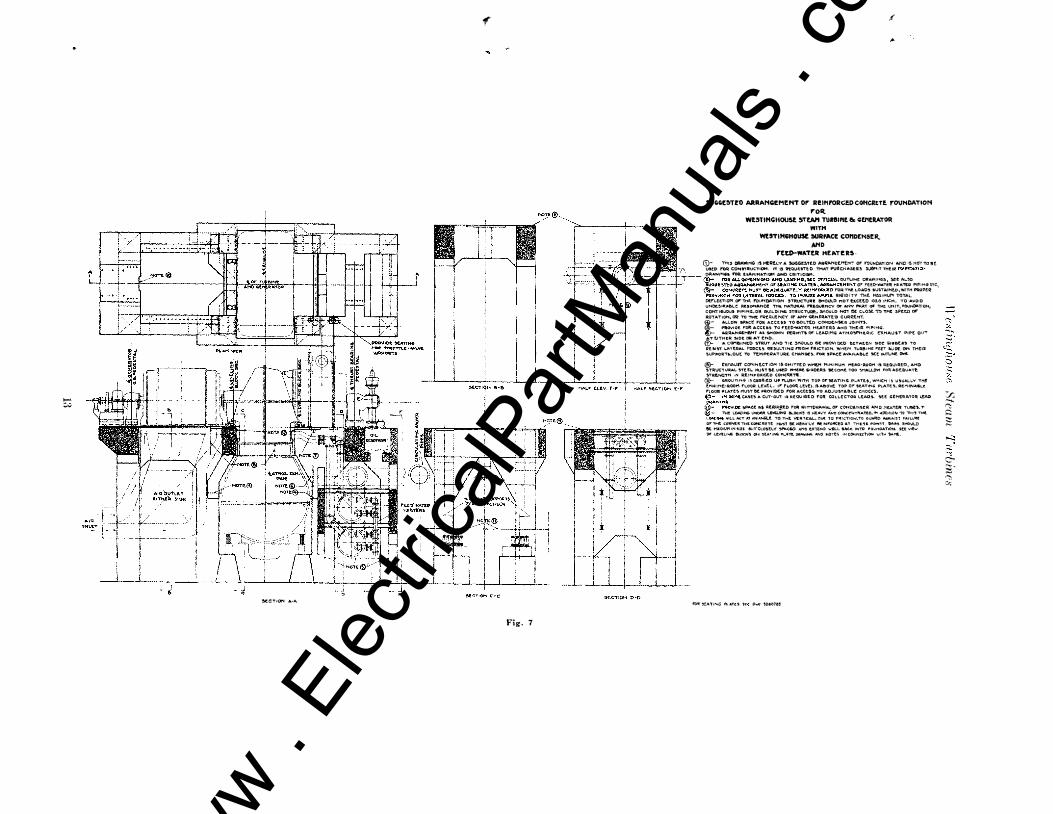
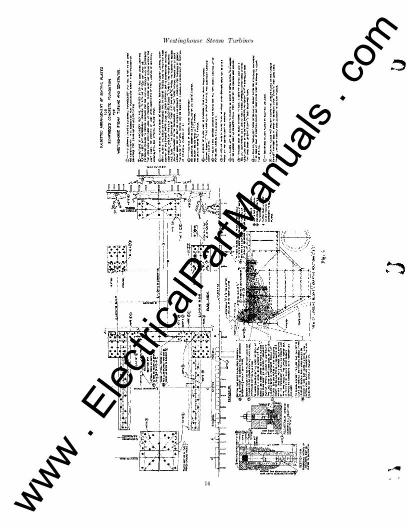
XC'TIQN A-A
-.uT!D AIIRANG£I'I!KT Of'ITaL FOUNDATION '0.
W'[$TING_ $TIN1 TUaIllNE80CZI'IERATOIt: W,,"
_STINIIHOUH SURl'M:E CON_ .NO
, fttD-WATER HfATElI$
�R e-:I:;:��:�.I�T �!
RR��V��:£T
S�!� ::��:it��U:H����:I::v�:T��!�:C:KO
"OR e::XAJ'1I N A T ION AND CR ITICISH. ®- WQJtKMAN»tlP aHOUlO t>f: "lUT�CL.A$!. Hi AL.1.. MlfTlCVLAR" IH¥tT HOLt� MUST MACCuttAttL"t'
$PActo $0 HOLU A R t CONTINU OUS. ANI) RI'ttT S OlilVIN 10 f1LI", e.UIl.T MI:.H15e::H "'U�T K"nIut. N'tD fllt:t ,.ROM 'TW15'TS. aw;,I(I.l!:s. Ol OPtf"4 .u:tINTS &t"TWt.fH C O�PONr:N'T F't!.C['. AauT"ING 1Iut:'.C�s. '" COI1PRf:$$ION t4CH&tR,$. UHl.n� fULI.Y ?L1Cr:.Oj Nun at "IMJSHtO TO IM5uRt [¥Cri COMTACT. AI..I..
$UAfAC[:$ IHACCC.UAe.L£ ArTtR A$1If.H8UNIi TO Sf 't"le:LL PAINTtO OR OtLtO 'rf'Pltt .,gMIIW..INc,. ®- "ORAl.!. QIMtN"IO�Af'lD LOAOI,,"" Xt Of"f,CfAL. OUTLIMt OQ:AWIN�l'J,. $U AL$,O :.1tAI'1INl.tTAN.O OAAIH PIPING QRAWIN;, AND ARAAM4tH!.N'T or f'ttQ·W6.Tt:R HtA'TtR PIPIMG. 6)- TO INsuRe; AMP!..!. RUlIOIT'( THe:. MA�II1UH TOTAl.. �nfCTION or"H� rOUNoAT10N �TttUC;TUItt $HO\A.D 1'10"1' e:v.cttO 'O'2.Q INCH. TO' AVOID UNt>UIR,A&L.t RUOHANet "Mt NATURAl. rRf.QlJtNC"f orloNY �T or THe: UNIT. rO'UHQA,TIOH. COf"lTj(UJOU� PIPINCil,OR e\t1\JIINr; $l1tIJCTWRC. )HOULO to(OT K tLOK TO THL Sf'UO or ItOTATIOH�Oft TO "fMC F'lt1tqt;01CV or Nt'( Gt.NUA'rQ CUA:RI!.H"t
®- . U .. �DlTiOH '1'0 'n4t 'lt1tTlet.LLOAD" �'TAiNtO TH[ S1"Q:UC:'1'URC HUi'T tiCAl'1p!'''f RUTlU.lNf.I) AGAiIGT LAn:;RAL M.ovt!"lCN'T DURING THr.. tRt:CTION fIi'ROt.UW;� AND TO Qtt.I!loT ftjRCU PWt To nICTIOH�.,;tN «.,..\N Of
Tttt TWI?e.!f'lC f"A1lT$ SLlDt OH 'mtlq $UPPOIlT$ Q!Jt TC "'I't.nPCM'ruAe: Ct<.I.NGl!.S. wct'( fOKct WILL QCeva AT'ntE.'OIJt L(vr. ... ING 8LOGlt'�"L" AND A'TTKt THIt\J!T-DtAltlf'lG �·Pl.ATt -11": fOIl PURPOS[� or D"I¢N 'n'IU£ f'OlH:t> NAV I5C: AS,.UMCD TO M �o'" Of1'l'*£ vtnlcAl.. L�'HQ, 'Tl1f "N ... Nf f'MOPt'II: II '&OlTW TO � )U"II'WA1'''I(·�
®- '" COHIJIf'jf.D :trAVT.AI'fO "TIC $MO'\)LD • f'R(NIOCD acTWUM ,.IOC GIRI)(IiI:!o TO Me: $I�T lATtJIAL 'Oleu. ,0It � ",vAI� M.r.. �1't.� \NLfT AND DAA'N PlPlffiio DRAWIHG,S. �. THICKNf�' or &eATING PI.A�!I ACCOHMtM to It. 21NCHtIlMINIMUM THICKNC!o$ lllHCHtIJ.
,VArACt or ,.UTlNG Pl.ATt� HUST ec 'TRUt AND Lf.vtL �ATING P\.ATtt. NttO MOT NEctu,uil.V ONP'ORf'1 To OI,1TLINt 01 HA.CH!fiAliI"( ntrr RtQVIMIHG �UWORT BUT Hun !It: UTt M!N'!. LHOVGl'1l'O "0'II1C)f!
$U/tf'ACr. roll' Tkt'iAA10O$ CHOC�AND'fItANSMI'f THt L.OAOTO THt !TAUCTVRf. pu.n! "'�T NOTt:c.TtMD WITHIN TI1t UHIT LINt!o. rOQ THf'K. L.INt S,DiMtN!!'ON! or rttT. 1.0 CA:T!OH Of' $Ol..T1NIIO AND LO ADIMC*.$U;, orrU::IAL OVTUNt t>Il AW 1NG$.
® DR'ILL!N". TAPPlNOANO 'VO'T�rAeING or !ot',AT1NG·PL.A'Tt$ roll' AJ),JU!lTAM.t cHoeU�Ltve::1..IN; BLOtlt$
--IOP9iff�:;:o.>orsl:.m;,-w='===r :�:u�������'f ,&�Uf5P��;O� ��R��;$ T
=I�L.��!�����;�:����A��N
��T!J���: �t�
T�op.'rM""
Fig_ 6
u
$1101.11..0 Dr: �urt'!CICNT 'WItT!! TO PUlL i>\RDtR'!o AND :.t,A'fIf'&-PLATCS INTO rntM CQMTACT, auT '!It:CTIONAL ARt A OF $t AT1NG4'LATr;!o !oH OUL.O NOT at Cot1$lDtCO I� CA.\.CULATiNG ,Utotll$.
Ii I jP=� . Ii , Ii <t.C��T����;:e:e!�;�:-:: !�:���
t�t::VATlOH r-1"
CO .... tR1NIIO eli\. y. TP'It :sn:�L ","ON� KING KIItIt AotOVATC rOl: THt LOAM IHPe!te. MlCi1 A�I", HAY I'1AI/e: ACLMLNT nNl5ti CASUI:It.O UP 'LUSH WITH"!"OP' or $CATING'pt.ATt5.WHICH f$U$IJALL'f'TttC tMG1Nt�ROOM r1..00Q-l.tVtL, If' nOOfH,tvtr.. \$A8cJI;t TOI> O'r �tA"!NG;PLA'ff!. I?tMOV,t,aLt f'l.OOR·'"1.ATt' �HOULO K PRCVIl)I!:[) _rort ACeu! TO /lll),JUST ..... C. c .. oelC$. ®- PRovlOe !�Att A5 IttOUIJttO rOR WITH�
or tONOCNKR AN O P1tATtA. Tuat_. @ � ALLO'W 5F>ACt rOR ACCtU 'TO 8ot.TCD CONOU't5fR JOINT!o. @- "o .... roe: rOR At etK 'TO rt::to·_nR HCA"'Jl:.�
snch as: Glue pots, immersion heaters, sulder pots, hat-making machinery and electric ovens.
Light ing systems Safety switches
For Power Plants and Transmission Lines
Circuit-breakers and switches Condensers Controllers Control Switches Frequency changers Fuses and fuse blocks Generators T nsulatillg material Instruments Lamps. incandescent and arc Lightning arresters Line material Locomotives .\f eters �fotors �Iotor-generators Porta b1c Power Stands, 110
volts Rectifiers Regulators Relays
Solder and soldering fluids Stokers Substations, portable and auto-
Electric ware, i 11 C 111 d i n g: Table stoves. toasters, irolls, warming pads, curling irons, coffee percolators, chafing dishes, disc stoves, radiators and sterilizers.
Automatic electric ranges Fans Incandescent lamps Radio Apparatus Small motors for driving cof
fee grinders, ice cream freezers, ironing machines, washing machines, vacuum cleaners, sewing machines, small lathes. polishing and grinding wheels. pumps and piano players.
Sew-motors
www . El
ectric
alPar
tMan
uals
. com
Westinghouse Electric & Manufacturing Companv East Pittsburgh, Pa.
----�
WESTINGHOUSE SALES OFFICES
\LBANY, N. Y .. Journal Bldg. ATLANTA, GA., Westinghouse Elec. Bldg., 426 Marietta St. BAKERSFIELD, CAL., 2224 San Emedio St. BALTIMORE, MD .. Westinghouse Elec. Bldg.,121 E. Baltimore St. BIRMINGHAM, ALA., Brown-Marx Bldg., 2000 First Ave. BLUEFIELD, W. VA., The Commercial Bank Bldg., Federal &
Commerce Sta. BOSTON, MASS .. Rice Bldg., 10 High Sl. BRIDGEPORT, CONN" Bruce & Seymour Streets. BUFFALO, N. Y., Ellicott Square Bldg .. Ellicott Square. BURLINGTON, IOWA, 315 North Third St. BUTTE. MONT .. Montana Electric Co. Bldg .. 52 East Broadway. CANTON, OHIO, (Box 292-Mail and Telegrams) CASPER. WYO., Turner Coffman Bldg •. 124 W. 2nd Ave. CEDAR RAPIDS. IOWA, 1616 Fifth Ave .• (Mail P.O. Box 1067) CHARLESTON, W. V A .• Kanawha National Bank Bldg., Capitol
and Virginia Streets. CHARLOTTE. N. C., Commerical Bank Bldg .. 200 S. Tryon St. CHATTANOOGA. TENN., Tenn. Elec. Power Co. Bldg., Market
and 6th Sts. CHICAGO, ILL., Conway Bldg .. 111 W. Washington Street. CINCINNATI, OHlo,Westinghouse Elec. Bldg.,Third and Elm Sts. CI,EVELAND, OHIO. Station "B," Westinghouse Electric Bldg.,
2209 Ashland Rd. S. E. COLUMBUS, 0., Interurban Terminal Bldg., Third and Rich Sts. DALLAS, TEX., Magnolia Bldg., Akard and Commerce Streets. DAYTON. 0" Reibold Bldg., 14 West Fourth Street. DENVER, COLO., Ga. & Electric Bldg .. 910 Fifteenth St. DES MOINES, IOWA, Equitable Bldg., W. 6th and Locust Sts. DETROIT, MICH., Westinghouse Elec. Bldg" 1535 Sixth St. DULUTH, MINN .. 511 Alworth Bldg., 306 West Superior St. ELMIRA, N. Y" Hulett Bldg .. 338-342 E. Water St. EI. PASO, TEX., Mills Bldg., Oregon and Mill. St. FORT WAYNE, IND" 1010 Packard Ave. FRESNO, CAL .. Griffith-McKenzie Bldg., J and Mariposa Sts. GRAND RAPIDS. MICH., 422 Kelsey Bldg., Pearl & Ottawa Sts. HAMMOND, IND., (Mail-P. O. Box 238; Telegrams�-1238
Jackson St.) HARTFORD, CONN., 220 Market St. HOUSTON. TEX., Union National Bank Bldg., Main St. and
Congtess Ave. HUNTINGTON, W. VA., Westinghouse Electric Bldg., Cor. Sec
ond A ve. and Ninth St, INDIANAPOLIS, IND .. Westinghouse Elec. Bldg .. 820 N. Senate
Ave. ISHPEMING, MICH .. 507 N. 5tb St. JACKSON, MICH., 704 Peoples National Bank Bldg. JACKSONVILL E, FLA., Union Terminal Building, East Union and
Ionia Sts. KANSAS CITY, Mo., 2126 Wyandotte St .. Gateway Station. KNOXVILLE, TENN., 413 Bankers Trust Bldg. LITTLE ROCK, ARK .. 2311 State Street. LOUISVILLE, Ky., Marion E. Taylor Bldg .. 312 Fourth Ave. Los ANGELES, CAL., Westinghouse Elec. Bldg .• 420 S. San Pedro
St. MADISON, WIS., 315 First Central Bldg. MEMPHIS, TENN .. Exchange Bldg .. 130 Madison Ave. MIDDLESBORO, Ky., (P. O. Box 518)
MILWAUKEE, W.s., First National Bank Bldg., 425 E. Water St, MINNEAPOLIS, M.NN .. Northwestern Terminal, 2303 Kennedy
St. N. E. NEWARK, N. J., 38-40 Clinton SI. NEW HAVEN, CONN., Liberty Bldg .• 152 Temple St. NEW ORLEANS, LA., Maison Blanche Bldg., 921 Canal St. NEW YORK, N. Y., 150 Broadway. NIAGARA FALLS, N. Y., Gluck Bldg., 205 Falls Street. NORFOLK, VA., 1122 National Bank of Commerce Bldg., 300
.Main St. OKLAHOMA CITY, OKLA., Tradesman's National Bank Bldg.,
Main & Broadway Sts. OMAHA, NED., llQ2 Woodman of the World Bldg., 1319 Farnam
St. PEORIA, ILL. , 417 Peoria Life Bldg., 214 Cooper SI. PHILADELPHIA, PA .. West. Elec.& Mfg. Bldg .. 30th & Walnut Sts. PITTSBURGH, PA., Chamber of Commerce Bldg., 7th & Smith-
field Sts. PORTLAND, MAINE, 61 Deering St. PORTLAND, ORE .. Porter Bldg., Sixth and Oak Sts. PROVIDENCE, R. I., 393 Harris Ave. RALEIGH, N. C .. 803 N. Person St. RICHMOND. VA" Room 912 Virginia Rwy. and Pro Bldg.
Seventh and Franklin Sts. ROCHESTER, N. Y., Chan.ber of Commerce Bldg., 119 E, Main,
Street. ROCK ISLAND. ILL., 2319 Third Avenue. SACO, MAINE, R. F. D. No. 2. ST. LOUIS, Mo .. Westinghouse Elec. Bldg., 717 So. Twelfth St. SALT LAKE CITY, UTAH, Interurban Terminal Bldg., W. Temple
and S. Temple St. SAN ANTONIO, TEXAS, 1105 Denver Blvd. SAN FRANCISCO, CAL., First National Bank Bldg., 1 Mont
gomery St. SEATTLE, WASH., Westinghouse Elec. Bldg., 3451 E. Marginal
Way. SHREVEPORT. LA" 432 Robinson Place. SPOKANE, WAb'H., Old National Bank Bldg .. Riverside &
Stevens Sis. SPRINGFIELD. ILL., Public Service BldJ( .. 130 S. Sixth St. SPRINGFIELD, MA�'" 82 Worthington Street. SYRACUSE, N. Y .. University Bldg.,S. Warren and E. Wash. Sts. TACOMA, WASH .. W. R. Rust Bldg" S. 11th and Commerce Sts. TERRE HAUTE. IND.,320Terre Haute Trust Bldg .. 7 35 Maple Ave. TOLEDO, 0., Ohio Bldg., Madison Avenue and Superior Street. TUCSON, ARIZ .. Immigration Bldg .. 90 Church Street. TULSA, OKLAHOMA. Mid-Continent Bldg., 5th & Boston Ave. UTICA, N. Y .. 408 Pine St. WASHINGTON, D. C, Hibbs Bldg .. 723 Fifteenth St .• N. W. WATERTOWN, N. Y, 254 Woolworth Bldg., Public Square. WICHITA, KANSAS, 3809 East English St. W[LKES-BARRE, PA., Miner's Bank Bldg., W. Market and
Franklin Sts. WORCESTER, MASS., Park Bldg .. 507 Main Street. YOUNGSTOWN, OHIO, Home Savings and Loan Bldg., Federal &
Chestnut Sts. Hunt-Mirk & Company. San Francisco. Cal .. 141 Second St.,
Marine Dept .. Special Pacific Coast Representatives. The Hawaiian Electric Company, Ltd., Honolulu, T. H.-Agent
WESTINGHOUSE AGENT -JOBBERS ATLANTA, GA., Gilham-Schoen Electric Co. BALTIMORE, MD., H. C koberts I!.lectric Supply Co, BIRMINGHAM:, ALA .• Moore-Handley Hardware Co. BLUEFIELD, WEST VIRGINIA, !'juperior bupply Co. BUFFALO, N. Y., McCarthy Bros. & Ford. BUTTE, br10NTANA, The Montana Electric Co. CHICAGO, ILL .. Illinois Electric Co. CHARLOTTE, N. C., Carolina States Electric Co. CLEVELAND, OHIO, '1 he Erner Electric Co. COLUMB[A, S. C, Mann Electric and Supply Co .. Inc. DENVER, COLO., The Mine & Smelter Supply Co. DETROIT, MICH.t Commercial Electric Supply Co. EL PASO, TEXAS, The Mine & Smelter Supply Co. ERIE, PA .• Star Electric CO. ];;VANSVIU-E, IND., The Varney Electric Supply Co. HOUSTON, TEXAS, Tel-Electric Co. HUNTINGTON. WEST VIRGINIA, Banks Supply Co. INDIANAPOLIS, IND., The Varney Electric Supply CO. JACKSONVILLE, FLA" Pierce Electric Co. KANSAS CITY, Mo .. Columbian Electrical Co. Los ANGELES, CAL .. lllinois Electric Co. LOUISVILLE, KY .. Tafel Electric Co. MEMPHIS, TENN., The Riechman-Crosby Co.
MILWAUKEE, WIS •• julius Andrae & Sons Co. M[NNEAPOLIS. MINN .. R. M. Laird I!.leclric Co. NEW HAVEN, CONN., The Hessel", Hoppen Co. NEW ORLEANS, LA .. Electrical Supply Co. NEW YORK, N. Y., Alpha Electric Co. OMAHA, NEB .. The McGraw Co. PHILADELPHIA, PA .. H. C. Roberts Electric Supply Co. PITTSBURGH, PA .. Robbins Electric Co. PORTLAND, ORE., Fobes Supply Co. RICHMOND, V A., Tower-Binford Electric & Mfg. Co. ROCHESTER, N. Y .. Rochester Electrical Supply Co. SALT LAKE CITY, UTAH. Inter��lountain Electric Co. SAN FRANCISCO, CAL .. Fobes Supply Co SCRANTON. PA., Penn Electrical hngineering Co. SEATTLE, WASH., Fobes Supply Co. SIOUX CITY, IOWA, The MeL-raw Co. SPOKANE, WASH., The Washington I!.lectric Supply Co. ST. LOUIS, Mo .. The McGraw Company. ST. PAUL, M[NN., St. Paul Electric Co. SYRACUSE, N. Y., H. C. Roberts Electric Supply Co. TAMPA, FLA., Pierce Electric Co. WASHINGTON, D. C, H. C. Roberts Electric Supply Co.
WESTINGHOUSE SERVICE SHOPS ATLANTA, GA .... _ � . � .�� �� .. � _.��_�� .... � ... � .. _ ......... 426 Marietta Street BALTIMORE, MD ... .. . � .... �.��.��.� .. . � .. � ........ 501 East Preston Street BOSTON, MASS ...... . � ... � .. �.�� .. � ... . �.� .... ��.� .... � .... . 12 Farnsworth Street BRIDGEPORT, COl'\';-", .._. _ _ . ____ ....• �_.vru\.e ,Ave. and Seymour Street BUFFALO, N. Y .. _� .. � ... ��._�_�� ..... � . .. _ ....... _ .... 141-157 Milton Street CHICAGO, ILL .. _._ .. � .. � ...... ...... � ................ _ .. 2201 W. Pershing Road CINCINNATI, Ol"v .. �� .. � .. �.� ......... � ... �� .. � ...... 1'hird and Elm Streets CLEVELAND, OHIO ... _ .. �� ... � .. � .. 2209 Ashland Rd .. S. E. DENVER, COLO .... � ... � .. ��. � .. �.lyOY·ll-13-15 Blake Street DETROIT, MICH •.... �.�.�. � .������.� .......... 1535 Sixth Street HARTFORD, CONN ... ��.... � � � � � � � � � � � .. � .. �� .. _ .. 220 Market Street HUNTINGTON, \'\1. \' ;l. .. ._ ....... :. .. H Street � Second Ave. INDIANAPOL.S, IND . . �.� �� �.� .. _ .. SI4-820 N. Senate Ave.
� �� � � � � � � . � � . � ....... .47 Messenger Street .� ...... l026 Wyandotte Street ��.�� .. 420 S. San Pedro Slreet .� .. �2303 Kenned y St., N. E. . .............. .467 Tenth Avenue NEW YORK, N. Y.��._.�