SAIMM, SANIRE and ISRM The 6 th International Symposium on Ground Support in Mining and Civil Engineering Construction W D Ortlepp, W C Joughin, A K Ward and J Thompson Page 561 REINFORCEMENT SUPPORT OF CONCRETE SHAFT LINING IN WESTONARIA FORMATION LAVA IN THE EZULWINI VERTICAL SHAFT SYSTEM W D W D Ortlepp* W C Joughin*, A K Ward + and J Thompson *SRK Consulting and + Seismogen Abstract Monolithic concrete-lined circular vertical shafts have been the preferred form of access to the deep ore-bodies of the South African gold-mines for than fifty years. Without any steel reinforcement the linings, almost without exception, have proved adequate in keeping shafts operating satisfactorily throughout the working life of the mines. The 1100m deep, 45 year old main shaft and its companion ventilation shaft at Ezulwini Mine (originally Western Areas Gold Mine) had both experienced some damage where they passed through the weak Westonaria Formation (WAF) horizon of the Ventersdorp Lava Group, during the 1980’s. This damage had required extensive repair work which appeared to have been adequate until the mine closed in 1999. In 2006, preparations for the extraction of the shaft pillar commenced and it was decided that the shaft should be rehabilitated to a fully-operational hoisting shaft with a planned life of 40 years. Shortly before, on a nearby mining operation, a sub-vertical shaft with a similar history of damage and repair was completely lost when weak lava from the same geological horizon broke through the concrete lining. The circumstances and timing of this event had a profound influence on the approach of the new owners toward the design and execution of the rehabilitation of the shaft. This paper discusses the new design philosophy and describes, in some detail, the innovative support technology that was consequently developed, tested and implemented. The main change in approach was to ensure that the reinforcing cable anchors and the containment cladding would resist long-term creep, survive any large displacement strains beyond the conventional elastic design limit and possess significant residual dynamic capacity to ensure that even a large seismic event could not cause significant damage to the shaft infrastructure. 1 Introduction Ezulwini Mining Company is in the process of preparing for a shaft pillar extraction at a depth of between 900 m and 1000 m below surface. While the stress levels are not excessive, the presence of the weak Westonaria formation lavas (WAF) in the shaft barrel poses a severe hazard, which must be managed through support design and mining layout. The design of mining layout and sequence is critical to the success of the shaft pillar extraction, but does not form part of the discussion here. This paper focuses on the design of the reinforcement support of the shaft concrete lining. The existence of the very weak WAF at the base of the Ventersdorp Lavas has caused severe ground control problems where it has been previously intersected in tunnels and shafts on Ezulwini and on neighbouring mines. Significant damage has been experienced in the
Transcript
SAIMM, SANIRE and ISRM
The 6th
International Symposium on Ground Support in Mining and Civil Engineering Construction
W D Ortlepp, W C Joughin, A K Ward and J Thompson
Page 561
REINFORCEMENT SUPPORT OF CONCRETE SHAFT LINING IN
WESTONARIA FORMATION LAVA IN THE EZULWINI VERTICAL
SHAFT SYSTEM
W D
W D Ortlepp* W C Joughin*, A K Ward+
and J Thompson
*SRK Consulting and +
Seismogen
Abstract
Monolithic concrete-lined circular vertical shafts have been the preferred form of access to the deep ore-bodies
of the South African gold-mines for than fifty years. Without any steel reinforcement the linings, almost without
exception, have proved adequate in keeping shafts operating satisfactorily throughout the working life of the
mines.
The 1100m deep, 45 year old main shaft and its companion ventilation shaft at Ezulwini Mine (originally
Western Areas Gold Mine) had both experienced some damage where they passed through the weak Westonaria
Formation (WAF) horizon of the Ventersdorp Lava Group, during the 1980’s. This damage had required
extensive repair work which appeared to have been adequate until the mine closed in 1999.
In 2006, preparations for the extraction of the shaft pillar commenced and it was decided that the shaft should be
rehabilitated to a fully-operational hoisting shaft with a planned life of 40 years. Shortly before, on a nearby
mining operation, a sub-vertical shaft with a similar history of damage and repair was completely lost when
weak lava from the same geological horizon broke through the concrete lining. The circumstances and timing of
this event had a profound influence on the approach of the new owners toward the design and execution of the
rehabilitation of the shaft.
This paper discusses the new design philosophy and describes, in some detail, the innovative support technology
that was consequently developed, tested and implemented.
The main change in approach was to ensure that the reinforcing cable anchors and the containment cladding
would resist long-term creep, survive any large displacement strains beyond the conventional elastic design limit
and possess significant residual dynamic capacity to ensure that even a large seismic event could not cause
significant damage to the shaft infrastructure.
1 Introduction
Ezulwini Mining Company is in the process of preparing for a shaft pillar extraction at a
depth of between 900 m and 1000 m below surface. While the stress levels are not excessive,
the presence of the weak Westonaria formation lavas (WAF) in the shaft barrel poses a severe
hazard, which must be managed through support design and mining layout. The design of
mining layout and sequence is critical to the success of the shaft pillar extraction, but does not
form part of the discussion here. This paper focuses on the design of the reinforcement
support of the shaft concrete lining.
The existence of the very weak WAF at the base of the Ventersdorp Lavas has caused severe
ground control problems where it has been previously intersected in tunnels and shafts on
Ezulwini and on neighbouring mines. Significant damage has been experienced in the
SAIMM, SANIRE and ISRM
The 6th
International Symposium on Ground Support in Mining and Civil Engineering Construction
W D Ortlepp, W C Joughin, A K Ward and J Thompson
Page 562
concrete linings of vertical shafts that have intersected this horizon in Ezulwini shaft itself and
in shafts on neighbouring properties.
The most dramatic example was that of South Deep’s SV1 sub-vertical shaft which was
completely destroyed below the reef intersection by a sudden major collapse of the concrete
lining and the weak rock behind. Since there had never been any stoping anywhere within
200m of the shaft and the mined-out span beyond was limited to about 800 m, it had to be
concluded that the failure was driven largely by time-dependent ‘creep’ processes rather than
by stress-induced fracturing. Significantly also, the collapse occurred suddenly during
rehabilitation operations that might have removed some of the small (but possibly crucially-
important) confinement afforded by the damaged portion of the concrete lining of the shaft.
The Ezulwini main shaft barrel itself had given cause for concern during its original service
life and some moiling of the damaged concrete and support of the lining had been done. A
certain number of cable anchors had also been installed. Because of lack of documentation it
is difficult to determine exactly what was installed and it is not possible to determine their
present condition. In the ventilation shaft a more visible and elaborate system of chains and
wire ropes has been loosely installed across the WAF section. It is not possible to ascertain
the condition of the ‘shepherds crook’ anchors which secure this network.
The fact that South Deep’s SV1 suffered a disastrous failure with a mining-induced stress
change of nearly zero, suggested that a conventional approach to the present Ezulwini
problem would be totally inappropriate. Because of this failure and the indisputable weakness
of the WAF formation together with its erratic, unpredictable distribution, a particularly strict
and conservative engineering approach would be adopted.
Since there was no nearby mining and therefore no mining-induced stress, the classical
engineering design approach of matching the strength capacity to the anticipated load demand
and moderating this with an assumed factor of safety, is considered to be not appropriate here.
While it is relatively simple to estimate the capacity of the steel support components that will
be installed, it is not possible to make a reliable estimate of the load or stress demand.
The rock mass ‘strength’ of the weakest portions of the WAF can only be estimated. While
the theoretical stress changes due to the planned shaft pillar extraction can be determined by
computer modelling, there is no way of reliably determining the effects that the stress change
would have on the surrounding rock mass. In particular the volume of WAF that might fail
and be mobilized to squeeze or flow cannot be calculated with any degree of confidence.
Also, the possibility that fault-related seismic events of significant magnitude might occur
during the mining of the shaft pillar, cannot be excluded.
To overcome the uncertainty, it is accepted, as a basic imperative, that the importance of the
shaft is so crucial that the over-riding principle should be to install as much capacity as
practically possible, in as dense a pattern of holes as can be drilled economically. Overall
effectiveness rather than optimum efficiency or initial cost economy should be the target.
Factor of safety is not a meaningful or useful concept in the context of ensuring the long term
operational stability of the Ezulwini shafts.
SAIMM, SANIRE and ISRM
The 6th
International Symposium on Ground Support in Mining and Civil Engineering Construction
W D Ortlepp, W C Joughin, A K Ward and J Thompson
Page 563
2 WAF in the Ezulwini shaft barrels
The Ventersdorp contact Reef (VCR) and Upper Elsburg conglomerates, which contain the
gold bearing strata, are overlain by the Venterdorp lava, which comprises WAF and the
Alberton lavas. The WAF is the most problematic material within the shaft pillar and was
intersected by the two shafts between 1030 m and 1060 m below surface (a few metres above
38 level). It is texturally, mineralogically and geochemically different from the Alberton
formation, which typically overlies it. The Alberton formation is typically very strong (>
200 MPa), with few joints, forming a very competent rock mass. The WAF, which is
invariably weaker (<100 MPa) and often contains very weak zones, is usually immediately
above the VCR. A study on the mineralogical and geochemical characteristics of the WAF
(Swartz et. al 1994) revealed four distinct units within the WAF and these are listed in Table
2.1. The presence of volcaniclastic sediments contributes to the weakness of this material, but
the major concern is the presence of talc. Talc is an extremely soft mineral (1 on Moh’s scale
of hardness) and breaks down when exposed to water. The W1b unit can contain as much as
50% talc and represents the greatest concern.
Table 2.1: Lithostratigraphy of the Klipriviersberg group lavas (from Swartz et. al
1994)
Formation Unit Description
Alberton Dark grey amorphous massive horizon with distinct porphyritic texture
W2b Sequence of ‘high magnesium basalt’ and ‘olivine cumulate’ zones. No
volcaniclastic sediments.
W2 W2a Thick olivine cumulate texture unit with massive and amygdaloidal
intervals. Chlorite, quartz and carbonate. Includes volcaniclastic breccias,
sulphides
W1b Massive talcose, high magnesium basalt. Talc and chlorite. Fine grained
black with carbonate veining, particularly in contorted horizons. Includes
volcaniclastic sediments
Westonaria
W1
W1a Massive and amygdaloidal basalt. Chlorite and quartz with some talc.
Includes volcaniclastic sediments
Geotechnical borehole logging and laboratory tests were carried out on exploration borehole
core. This revealed an average RMR of 45 and Q of 2 for the WAF lava. The uniaxial
compressive strength ranged from 45 MPa to 138 MPa, with an average of 92 MPa. Slake
durability tests carried out on WAF material yielded very high durability results (> 98% after
4 cycles).
However, significant deterioration of the WAF had been observed in the shafts and in tunnels,
which are more than 30 years old, it was felt that the average RMR and Q values obtained
from the borehole logging were in fact too high for the WAF lava immediately around
existing excavations. Further investigation revealed that boreholes, which started in or near
the WAF, yielded the lower RMR values. It was evident that the WAF deteriorates over
many years due to exposure to air and water.
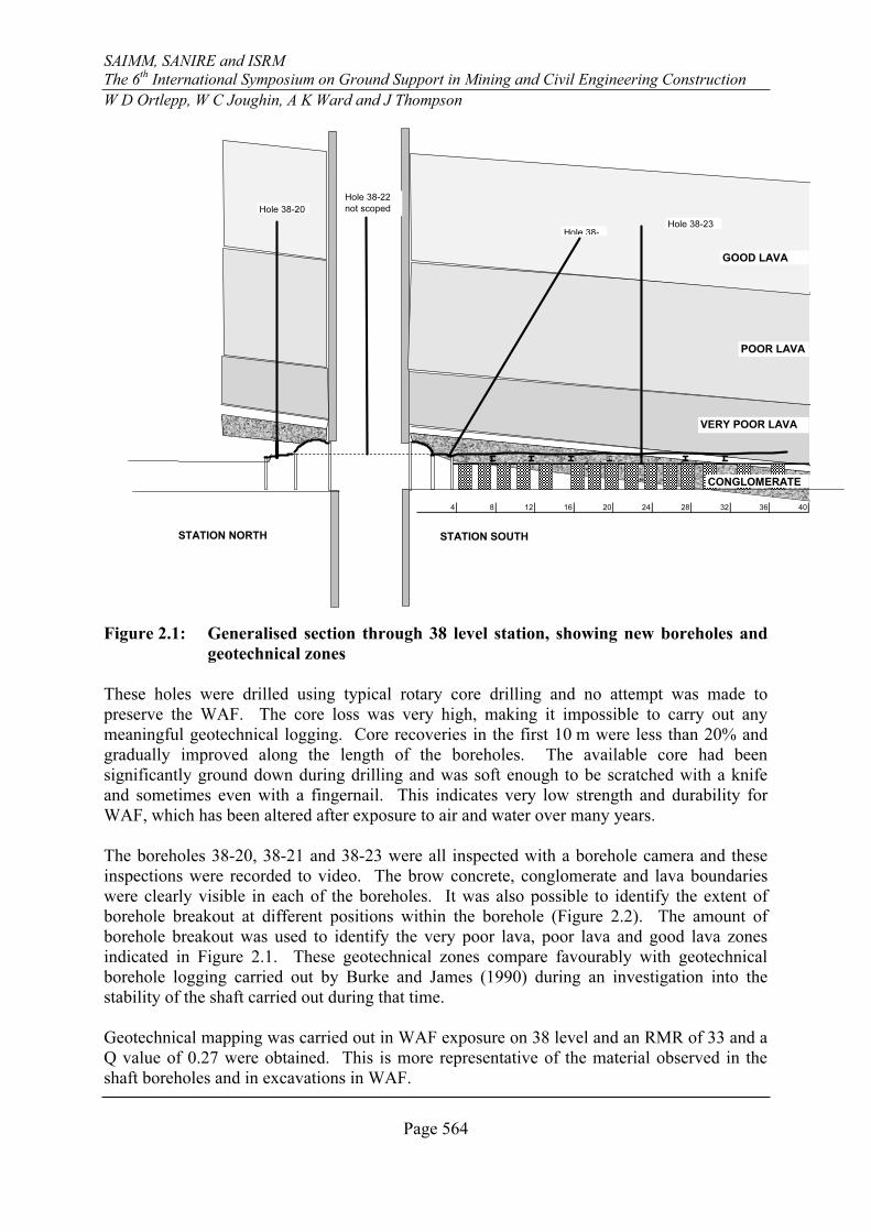
Four boreholes (38-20, 38-21, 38-22 and 38-23) were drilled up from 38 level, near the Main
shaft, to obtain more information on the WAF in the shaft barrel (Figure 2.1). Three of the
boreholes were drilled from the catwalk around the shaft (38-20, 38-21 and 38-22) and
therefore provide a good indication of the condition of the WAF in the shaft barrel.
SAIMM, SANIRE and ISRM
The 6th
International Symposium on Ground Support in Mining and Civil Engineering Construction
W D Ortlepp, W C Joughin, A K Ward and J Thompson
Page 564
4 8 12 16 20 24 28 32 36 40
Hole 38-23
Hole 38-
Hole 38-22
not scopedHole 38-20
GOOD LAVA
POOR LAVA
VERY POOR LAVA
CONGLOMERATE
STATION SOUTHSTATION NORTH
Figure 2.1: Generalised section through 38 level station, showing new boreholes and
geotechnical zones
These holes were drilled using typical rotary core drilling and no attempt was made to
preserve the WAF. The core loss was very high, making it impossible to carry out any
meaningful geotechnical logging. Core recoveries in the first 10 m were less than 20% and
gradually improved along the length of the boreholes. The available core had been
significantly ground down during drilling and was soft enough to be scratched with a knife
and sometimes even with a fingernail. This indicates very low strength and durability for
WAF, which has been altered after exposure to air and water over many years.
The boreholes 38-20, 38-21 and 38-23 were all inspected with a borehole camera and these
inspections were recorded to video. The brow concrete, conglomerate and lava boundaries
were clearly visible in each of the boreholes. It was also possible to identify the extent of
borehole breakout at different positions within the borehole (Figure 2.2). The amount of
borehole breakout was used to identify the very poor lava, poor lava and good lava zones
indicated in Figure 2.1. These geotechnical zones compare favourably with geotechnical
borehole logging carried out by Burke and James (1990) during an investigation into the
stability of the shaft carried out during that time.
Geotechnical mapping was carried out in WAF exposure on 38 level and an RMR of 33 and a
Q value of 0.27 were obtained. This is more representative of the material observed in the
shaft boreholes and in excavations in WAF.
SAIMM, SANIRE and ISRM
The 6th
International Symposium on Ground Support in Mining and Civil Engineering Construction
W D Ortlepp, W C Joughin, A K Ward and J Thompson
Page 565
Figure 2.2: Borehole breakout “dog-earing” observed in borehole 38-20.
3 Historic rehabilitation in WAF material in the Ezulwini Main and Ventilation
shafts
The instability problems associated with Ezulwini Main shaft and remediation measures
undertaken are described in White (1988) and Lourens and White (1988). The sinking of the
6.7 m diameter ventilation shaft commenced on 20 January 1960 and was completed to the
final depth of 1102 m below collar on the 29 August 1960. Sinking of the main shaft
(7.925 m diameter) was started on 13 March 1960 and the final depth of 1518 m below collar
was reached on 3 March 1961.
The problems were first highlighted in September 1982, when investigations showed that the
reef pass, between 36 and 38 levels, had scaled to within 8 m of the Main shaft. The reef pass
was subsequently waste and grout filled to stabilise the area.
Following further instability during the first 6 months of 1984, 100 ton pre-stressed grouted
anchors were installed to stabilise the 38 level station brow and shaft barrel. The shaft
steelwork was also modified during this time. Five sets of buntons were cut away from the
barrel and suspended from above.
During December 1986, 6 displacement transducers were installed at bunton levels 220 and
221 (±4 m above the 38 station brow). Closure displacements of up to 50 mm and 19 mm
were recorded in the North East and South East compartments in 1988. The high closure
displacements correlated with the area then most affected by cracking of the concrete lining.
During most of the operational life of the shaft, it had been necessary to moil the East and
West sides of the shaft in the affected area on a number of occasions to provide clearance for
the skips.
The deformation was considered to be of a time dependant nature and directly associated with
the WAF.
SAIMM, SANIRE and ISRM
The 6th
International Symposium on Ground Support in Mining and Civil Engineering Construction
W D Ortlepp, W C Joughin, A K Ward and J Thompson
Page 566
There are no records of deformation available since this time, but it appears that with support
installed and limited mining taking place subsequently, the shaft has not experienced
significant further deformation. The conditions and remediation measures observed in the
Main and Ventilation shafts are shown schematically in Figure 3.1 and Figure 3.2.
The support installed prior to 1988 may have corroded and its performance cannot be
guaranteed. Corrosion is evident on the exposed portions of the support units and some have
failed.
33 level
36 level
38 level
38A level
Concrete lining
intact, good
condition
Concrete lining
intact, good
condition
Original lining damaged and re-
habilitated with multi-strand
anchors, shotcrete, trusses at 38
brow. Mini-tower installed
Concrete lining
intact, good
condition
Concrete lining
intact, good
condition
37 m
WAF
38 brow re-supported with multi-strand
anchors and tie backs
Figure 3.1: Historical support and remediation measures observed in the main shaft
SAIMM, SANIRE and ISRM
The 6th
International Symposium on Ground Support in Mining and Civil Engineering Construction
W D Ortlepp, W C Joughin, A K Ward and J Thompson
Page 567
33 level
36 level
38 level
38A level
Concrete lining
intact, good
condition
Concrete lining
intact, good
condition
10 mm chain link, secured in 1.0m
diamond pattern from 37m above 38
brow, concrete bulking in 17 m
section on NE sidewall
Concrete lining
intact, good
condition
Concrete lining
intact, good
condition
37 m
WAF
Figure 3.2: Historical support and remediation measures observed in the ventilation
shaft
4 Design philosophy
The main purpose of the design is to ensure safe, efficient and continuous use of the shafts for
the extraction of the multi-layered and sometimes massive gold-bearing strata within the shaft
pillar area. This requires that adequate provision be made for inevitable convergence and ride
movements that will be considerably greater than is usually experienced in shaft pillar mining,
and the possibility of significant seismic activity.
The fact that there is no other access shaft on the property dictates that there is no viable way
to access the pillar area other than via the Ezulwini shaft itself. Long term requirements may
justify another shaft at a different location but prevailing economic circumstances leave no
alternative, other than rehabilitation of the existing infrastructure.
The identification of the mechanisms of deformation and failure of the weak WAF mass is of
key importance in the process. As there is only one previous case (South Deep SV1 shaft)
where complete failure has occurred it is not possible to understand what the actual failure
process was. A multi-disciplinary design workshop team, comprising SRK rock engineers,
RSV project engineers, support contractors and mine production personnel was established.
The team has used collective experience to visualize a range of possible failure modes and
then assess how the damage could be contained by a reinforcing/supporting system that would
fit within the operational constraints of a main hoisting shaft.
In addition the experience and insights of others who were involved with the investigation of
the SDSV1 were sought. In particular the view of T Rangasamy was accepted, namely that
SAIMM, SANIRE and ISRM
The 6th
International Symposium on Ground Support in Mining and Civil Engineering Construction
W D Ortlepp, W C Joughin, A K Ward and J Thompson
Page 568
“….. the WAF should be characterized as a very weak squeezing material with a strong creep
potential….”. Enquiries were also pursued into certain instances where problems of tunnelling
and stoping through WAF on neighbouring mines had been successfully overcome.
Two things appeared to be widely accepted. The practice of injecting a two-component resin
at low pressure into the rock surrounding excavations, was usually very beneficial in
improving the condition of the WAF. Where collapses had occurred there had usually been
some indication of impending danger with preliminary symptoms developing with time. This
suggested that ‘best practice’ would certainly include the use of resin injection wherever
possible and the use of sophisticated automated monitoring technology in affected areas.
Due to the complex creep behaviour of the WAF rock mass, it is not practical to set numerical
values for the design criteria applicable to the several components of the support system.
Therefore, a “multi barrier” design was adopted. This entails the application of several
support systems, each providing a different support function. This means that for the most
part, a considerable degree of ‘back-up’ capability is provided. If deformation or
displacement exceeds an initial critical level and some failure occurs in one support element
then a second set of elements will come into play. All support systems will need to fail before
a major failure occurs.
Essentially, the over-riding requirement is to provide the maximum possible long-term
resistance to movement of the weak rock mass together with the ability to survive possible
extreme over-loading of short duration such as might result from a large seismic event.
Obviously these requirements must be provided in a practicable way that fits in with the tight
clearances and operational constraints of a normally functioning hoisting shaft.
In broad terms therefore, the following requirements were established as being necessary to
minimise the possibility of significant damage occurring during the life of the shaft.
• The existing confinement of the weak rock behind the concrete lining should be
maintained intact as far as possible. Some moiling will be necessary where
excessive bulking has taken place and cage clearance is compromised.
• The ‘hoop stress’ capacity of the lining must be supplemented by a stiff, strong
cladding.
• The weak-rock ‘squeezing ground’ in the cylindrical annulus beyond the shaft
barrel must be consolidated and strengthened by grout injection
• During consolidation, the cylindrical annulus should be reinforced with a dense
array of stiff, strong tendons.
• The resulting reinforced thick ‘shell’ of cladded concrete and strengthened rock
must be tied or anchored back to the surrounding rock mass with the maximum
possible retaining force by means of long anchors.
SAIMM, SANIRE and ISRM
The 6th
International Symposium on Ground Support in Mining and Civil Engineering Construction
W D Ortlepp, W C Joughin, A K Ward and J Thompson
Page 569
• These anchors must be able to survive large amounts of elongation and high
ground accelerations due to seismic events without compromising their initial
“stiffness”.
• The combined cladding, which consists of the original lining strengthened by a
strong, shotcrete-stiffened steel screen, will form a load-distribution diaphragm
that will spread the point loading of the anchors and injection rods more uniformly
over the weak WAF layer.
• The long-term serviceability of all the steel components in respect to their
extension capacity, their rockburst resistance and their corrosion life must be
specifically considered and optimized in the total design.
5 Method of Shaft Barrel Support
It is assumed that the concrete lining, normally of 30 MPa compressive strength, has zero
‘hoop strength’ over the WAF intersection because it has already failed or been moiled away
in places.
The main thrusts in the support strategy are:
i) rock consolidation and reinforcement by resin injection
ii) construction of strong cladding (surface support in the form of steel screen
panels and shotcrete)
iii) ‘tie back’ anchoring of the cladded, reinforced rock annulus by means of cable
anchors that possess considerable dynamic capability (via Duracables) and are
pre-stressed on installation
iv) Yielding straps to prevent any large blocks from falling into the shaft.
5.1 Rock consolidation and reinforcement
The Wimico system of resin-reinforcement was adopted because of its history of success in
horizontal workings in neighbouring mines. Holes are drilled by pneumatic percussion drills
(S36) at a grid-spacing of 0.95 m x 0.95 m using Wilborex 30/11 injection rods as the drilling
rods. The length of the Wilborex is, alternately, 6 m and 4 m and the hollow bar is left in the
completed hole to serve as the conduit for injection of the two-component liquid resin. The
continuous (left-hand) thread of the Wilborex ensures that the tensile strength of the steel bar
is closely coupled to the concrete lining and the jointed rock continuously along its full
length.
The strength of the bar is nominally 320 kN. These are installed in 0.95 m x 0.95 m pattern.
Theoretically, the radial confinement σhr
on the weak WAF immediately behind the concrete
lining would be 350kN/m2
.
SAIMM, SANIRE and ISRM
The 6th
International Symposium on Ground Support in Mining and Civil Engineering Construction
W D Ortlepp, W C Joughin, A K Ward and J Thompson
Page 570
The support resistance provided by the Wilborex rods is passive, requiring dilation (volume
increase) of the WAF before the resistance is activated. With effective full-column grouting,
the high stiffness of the rods would ensure that the required dilation is small (of the order of a
few milli-strains). The load in the bar is transferred to the concrete lining through a 20 mm
thick steel plate of 200 mm diameter.
Protection against corrosion will be provided by the resin and a 20 mm layer of dense
shotcrete.
5.2 Steel screen panels and shotcrete
The concrete linings of both the main shaft and the ventilation shaft have failed in places
across the respective WAF intersections. In order to prevent bulging of the low strength
‘mobile’ lava through the failed or weakened lining between the 0.95 m spaced Wilborex
injection rods, the lining needs to be strengthened. Pre-formed, curved panels of heavy
metallurgical screen provide a cladding layer that possesses multi-directional strength and a
degree of dynamic ductility. The ductility reduces the risk of ejection of blocks of concrete
that might result from a seismic event. A high strength, high density shotcrete, sprayed over
the screen panels, improves the stiffness of the cladding and provides additional corrosion
protection.
5.2.1 Dimensions and pattern
The screen is woven from 10 mm diameter crimped wires at 110 mm centre spacing in both
weft and warp directions. To ensure continuity of strength between adjoining sections of
cladding the screen is formed into panels of 1.87 m x 1.87 m by welding the wire ends to a
surrounding frame of 22 mm diameter round mild steel bar, Figure 5.1.
SAIMM, SANIRE and ISRM
The 6th
International Symposium on Ground Support in Mining and Civil Engineering Construction
W D Ortlepp, W C Joughin, A K Ward and J Thompson
Page 571
Figure 5.1: Steel screen panels
5.2.2 Strength
The load extension characteristic of the screen wire is given in Figure 5.2 with an ultimate
tensile strength (UTS) of 44 kN per wire. The total tensile strength in-plane, in both vertical
and horizontal directions, is 1500 kN.
A second function of the panels is to provide improved area load distribution of the ‘point-
loading’ from the Wilborex rods. This will require the woven screen panels to be stiffened
and closely-coupled to the existing concrete lining by means of ultra high quality (60 MPa)
shotcrete. This will transfer and distribute the 500 kN ‘point load’ of the twin 18 mm
diameter Duracable anchors into a more uniform restraint which will contain any bulging of
possible weak patches in the lining and will effectively prevent any possibility of break-
through collapse of WAF through the 1.9 m spacing between anchors. Proper bonding of
shotcrete to steel to lining will contrive a ‘composite’ effect to the combined concrete
lining/steel screen cladding.
SAIMM, SANIRE and ISRM
The 6th
International Symposium on Ground Support in Mining and Civil Engineering Construction
W D Ortlepp, W C Joughin, A K Ward and J Thompson
Page 572
0
5
10
15
20
25
30
35
40
45
50
0 20 40 60 80 100
Deformation [mm]
Lo
ad
[kN
]
Figure 5.2: Screen panel wire load deformation characteristic for a 1.05 m test length
5.2.3 Surface testing
A series of surface tests was conducted on screen panels at the Savuka drop test facility near
Carletonville. A total of 7 tests was conducted of which 4 were statically loaded and 3 were
dynamically loaded. Two of the seven screen panels were sprayed with a 70 mm layer of
60 MPa shotcrete. In each test, the screen panel was bolted to a square steel frame (Figure
5.3). The bolting positions represent the four Wilborex bolts in the actual underground
design. Steel and wooden blocks were placed on top of the screen panel in between the four
bolts to simulate a punch load.
During static loading, a 10.3 tonne weight was then lowered onto the blocks on the screen
panel. The static tests comprise a loading phase, an unloading phase and a reloading phase.
The test arrangement allowed the screen panels to be deflected more than 300 mm, before the
weight was arrested on the frame. The applied loads were measured using a suspended tensile
load cell and induced deflections were measured using measuring tapes and a dumpy level.
The weight was stopped at regular intervals to record measurements. During the reloading
phase the weight was not stopped to take measurements, to simulate a higher rate of loading.
SAIMM, SANIRE and ISRM
The 6th
International Symposium on Ground Support in Mining and Civil Engineering Construction
W D Ortlepp, W C Joughin, A K Ward and J Thompson
Page 573
Heavy duty steel
mounting frame
10.3 tonne weight
Measuring tapes
Panel screen
Figure 5.3: Panel screen test arrangement for static loading
The test arrangement was modified for dynamic load testing. The maximum deflection had to
be limited in order to stabilise the arrangement. Durapack blocks were also placed on top of
the steel frame to cushion the steel frame when it arrested the steel weight. This further
reduced the available deflection. Two 2 MN compressive load cells were installed, below the
steel mounting frame, to measure the impact loads and replace the suspended tensile load cell.
These provide a fairly rudimentary means of estimating the impact loads. A 200 mm travel
Linear Variable Displacement Transducer (LVDT) was used to measure deflection. A spider
8 data logger allowed data capture at a frequency of 2400 Hz. The 10.3 tonne weight is
dropped from a suspended height of 100 mm to provide an impact velocity of 1.4 m/s.
A comparison of the load/deflection characteristics for different cases is shown in Figure 5.4.
Under static loading, screen panels (without shotcrete) strain harden and become stiffer with
increased deflection during the first phase. After the initial loading and unloading phases, the
screen panels maintain a residual deflection of 215 mm, which is 70% of the maximum
deflection during the loading phase. During the reloading phase, the stiffness of the screen
panels was much greater (0.49 MN/m) than during the initial loading phase (0.114 MN/m.).
The residual deflection and increased stiffness is mainly due to straightening of the crimped
wires.
The shotcrete screen panel displayed a substantially stiffer response of 1.22 MN/m until
cracking of the shotcrete occurred and reduced to 3.67 MN/m during strain hardening. The
10 tonne weight is supported at maximum deflection. This shows the importance of applying
the shotcrete.
The dynamic test results in Figure 5.4 represent the responses of two screen panels (one plain
and one with shotcrete) under dynamic loading conditions (1.4 m/s). During the shotcreted
screen panel test, the shotcrete provided a high initial stiffness, until it failed. The screen
panel continued to deform until the weight was fully arrested by the screen panel and
SAIMM, SANIRE and ISRM
The 6th
International Symposium on Ground Support in Mining and Civil Engineering Construction
W D Ortlepp, W C Joughin, A K Ward and J Thompson
Page 574
durapack blocks. No failure of the steel screen panel occurred. The LVDT, which was fixed
to the shotcrete, became detached when the shotcrete failed. The curve in Figure 5.4 is cut off
where durapack blocks begin to influence the test results. The maximum deformation,
measured physically, was 150 mm. The plain screen panel deforms at substantially lower
stiffness and is allowed to deform more due to the test arrangement. The energy absorption
can be determined from the area under the load deflection curve. The addition of shotcrete
increases the energy absorption capability from about 0.8 kJ to 9.8 kJ over the first 80mm of