Wet/Dry classification method with reflect and incident light observed from single camera Tomoaki Teshima†, Yuko Uematsu†, Hideo Saito†, Masayoshi Shimizu‡ †School of Science and Technology, Keio University 3-14-1 Hiyoshi Yokohama Kanagawa 223-8522, Japan ‡Fujitsu Laboratories Ltd 4-1-1 Kamikodanaka Kawasaki Kanagawa 211-8588, Japan Email: {tomoaki, yu-ko, saito}@ozawa.ics.keio.ac.jp, [email protected]Abstract In this paper, a method is proposed to detect a wet road area. The detection is based on the analysis of the reflection and the incident light. To obtain both reflection and the incident light from a single camera, the environment 3D shape is assumed that it can be modeled by 3 planes. Finaly, the efficiency is shown by the experiments. 1. Introduction Recently, there are many researchers who work in the area of Intelligent Transport System (ITS). Specially, there is a great interest in the assist system for a safety drive which is mounted on the vehicle. The ITS can be divided in to 2 categories, whether the system it self is mounted on the vehicle, or not. The system mounted on the vehicle will process the information collected from the outside of the vehicle, and estimate or detect useful information for the safety drive. In this paper, we propose a method which classifies the area on the road to dry, wet or indeterminable area. Pro- posed method uses the information obtained from a single camera, fixed on the vehicle. Wet detection is based on the statistics of the reflection intensity. A wet road is dangerous compared to a dry road since the surface of the road is slippery. In previous works, many re- searchers used a polarization camera [2] or a camera fixed above the road[2, 3]. Compared to them, the proposed method uses a normal camera fixed on the vehicle. This is a big difference against the previous methods. The polar- ization lens is unnecessary, and camera can move as long as it is fixed on a vehicle. The road map of the wet area will be created after the vehicle run on the road. In a near research field, polarization lens is used in the reflection analysis. Miyazaki et al. proposed a reflection analysis method to estimate the surface shape of the trans- parent objeects[4]. Yanghai et al. proposed a reflection separation method based on multilayer method[5]. The defference between the proposed method is that they sepa- rate the reflection. On the other hand, the proposed method compute the incident light from a single image. Our method is composed by 3steps. First, the compute a spatial temporal image by registrating the top-view images. Next, the method computes the incident light corresponds to each area. Finaly, the area is classified to 3 types:wet, dry or indeterminable. The originality of the proposed method is the estimation of the incident light by using the environ- mental shape information. The incident and reflection is obtained by single camera. The rest of this paper is organized as follows. Section 2 explains the wet road surface reflection attribution and the incident lights. Section 3 explains the method in each step, and Sec. 4 demonstrates the efficiency of the proposed method. 2. Theory In this section, the reflection attribute and the computa- tion of the incident light is described. 2.1. Specular reflection When we compare between a dry asfart road and a wet surface, the largest difference is the reflection. The dry road looks grey, and the color is uniform along the road. The color is uniform since the surface has strong random re- flection attribute. Thus, the reflection on the dry road is independent from the angle. On the other hand, wet road surface shows different re- flection attribute compared to the dry one. A damp road surface looks darker than the dry surface. This reflection light is trapped inside the moisture on the surface. If the road is wet enough, that it’s covered by water, then the sur- face makes specular reflections. Since the vehicle runs on the road, we can collect the reflection strength from different angle in the time domain. If the reflection strength changes due to the angular change, the surface has specular reflection. On the other hand, if it doesn’t change, it can have 2 possibilities. first is that it has no specular attribute. second is the incident light did not change. - 90 -
Transcript
Wet/Dry classification method with reflect and incident light observed fromsingle camera
Tomoaki Teshima†, Yuko Uematsu†, Hideo Saito†, Masayoshi Shimizu‡†School of Science and Technology, Keio University
In this paper, a method is proposed to detect a wet roadarea. The detection is based on the analysis of the reflectionand the incident light. To obtain both reflection and theincident light from a single camera, the environment 3Dshape is assumed that it can be modeled by 3 planes. Finaly,the efficiency is shown by the experiments.
1. Introduction
Recently, there are many researchers who work in thearea of Intelligent Transport System (ITS). Specially, thereis a great interest in the assist system for a safety drivewhich is mounted on the vehicle. The ITS can be dividedin to 2 categories, whether the system it self is mountedon the vehicle, or not. The system mounted on the vehiclewill process the information collected from the outside ofthe vehicle, and estimate or detect useful information forthe safety drive.
In this paper, we propose a method which classifies thearea on the road to dry, wet or indeterminable area. Pro-posed method uses the information obtained from a singlecamera, fixed on the vehicle. Wet detection is based on thestatistics of the reflection intensity.
A wet road is dangerous compared to a dry road since thesurface of the road is slippery. In previous works, many re-searchers used a polarization camera [2] or a camera fixedabove the road[2, 3]. Compared to them, the proposedmethod uses a normal camera fixed on the vehicle. Thisis a big difference against the previous methods. The polar-ization lens is unnecessary, and camera can move as longas it is fixed on a vehicle. The road map of the wet area willbe created after the vehicle run on the road.
In a near research field, polarization lens is used in thereflection analysis. Miyazakiet al. proposed a reflectionanalysis method to estimate the surface shape of the trans-parent objeects[4]. Yanghaiet al. proposed a reflectionseparation method based on multilayer method[5]. Thedefference between the proposed method is that they sepa-rate the reflection. On the other hand, the proposed methodcompute the incident light from a single image.
Our method is composed by 3steps. First, the compute aspatial temporal image by registrating the top-view images.Next, the method computes the incident light correspondsto each area. Finaly, the area is classified to 3 types:wet, dryor indeterminable. The originality of the proposed methodis the estimation of the incident light by using the environ-mental shape information. The incident and reflection isobtained by single camera.
The rest of this paper is organized as follows. Section2 explains the wet road surface reflection attribution andthe incident lights. Section 3 explains the method in eachstep, and Sec. 4 demonstrates the efficiency of the proposedmethod.
2. Theory
In this section, the reflection attribute and the computa-tion of the incident light is described.
2.1. Specular reflection
When we compare between a dry asfart road and a wetsurface, the largest difference is the reflection. The dry roadlooks grey, and the color is uniform along the road. Thecolor is uniform since the surface has strong random re-flection attribute. Thus, the reflection on the dry road isindependent from the angle.
On the other hand, wet road surface shows different re-flection attribute compared to the dry one. A damp roadsurface looks darker than the dry surface. This reflectionlight is trapped inside the moisture on the surface. If theroad is wet enough, that it’s covered by water, then the sur-face makes specular reflections.
Since the vehicle runs on the road, we can collect thereflection strength from different angle in the time domain.If the reflection strength changes due to the angular change,the surface has specular reflection. On the other hand, if itdoesn’t change, it can have 2 possibilities. first is that it hasno specular attribute. second is the incident light did notchange.
- 90 -
�
�
�
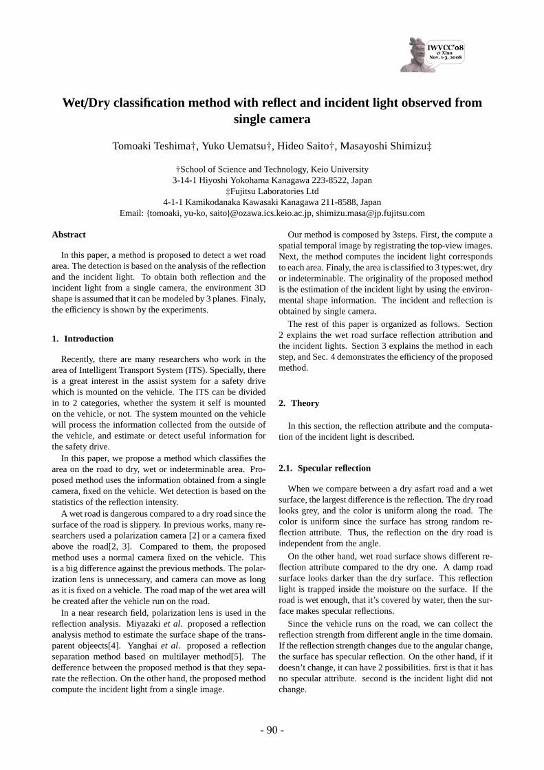
Figure 1: Draft image of the specular reflection and therandom reflection
2.2. Incident light
The classification between the dry area and the areawhich doesn’t have enought change in the incident lightrequires the observation of the incident light.
If the camera is heading along the direction of the vehi-cle, both road and the environment must be captured in 1image. If the distance between the camera and the environ-ment objects are known, The position where the incidentlights come from can be computed.
In sec. 3.2, we explain about the incident light computa-tion. In this paper, instead of estimating the environmentalshape, we assume that shape can be modeled by 3 planes.
3. Method
Proposed method is composed by 3 steps. First steptracks the points on the road to create a spatial temporalimage. The second step is the computation of the featurefrom the spatial temporal image. The third step is the clas-sification using 3 thresholds.
3.1. Tracking
For the tracking of the points on the road, we apply thetracking method proposed by Teshimaet al[6].
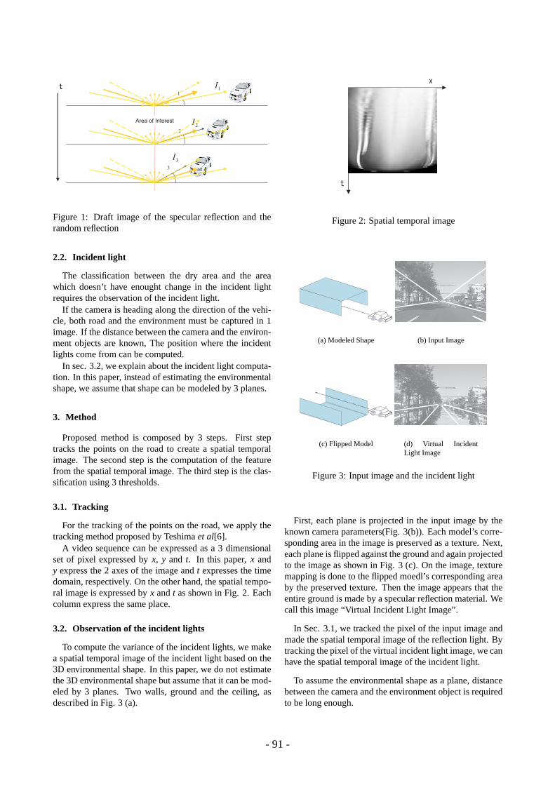
A video sequence can be expressed as a 3 dimensionalset of pixel expressed byx, y and t. In this paper,x andy express the 2 axes of the image andt expresses the timedomain, respectively. On the other hand, the spatial tempo-ral image is expressed byx andt as shown in Fig. 2. Eachcolumn express the same place.
3.2. Observation of the incident lights
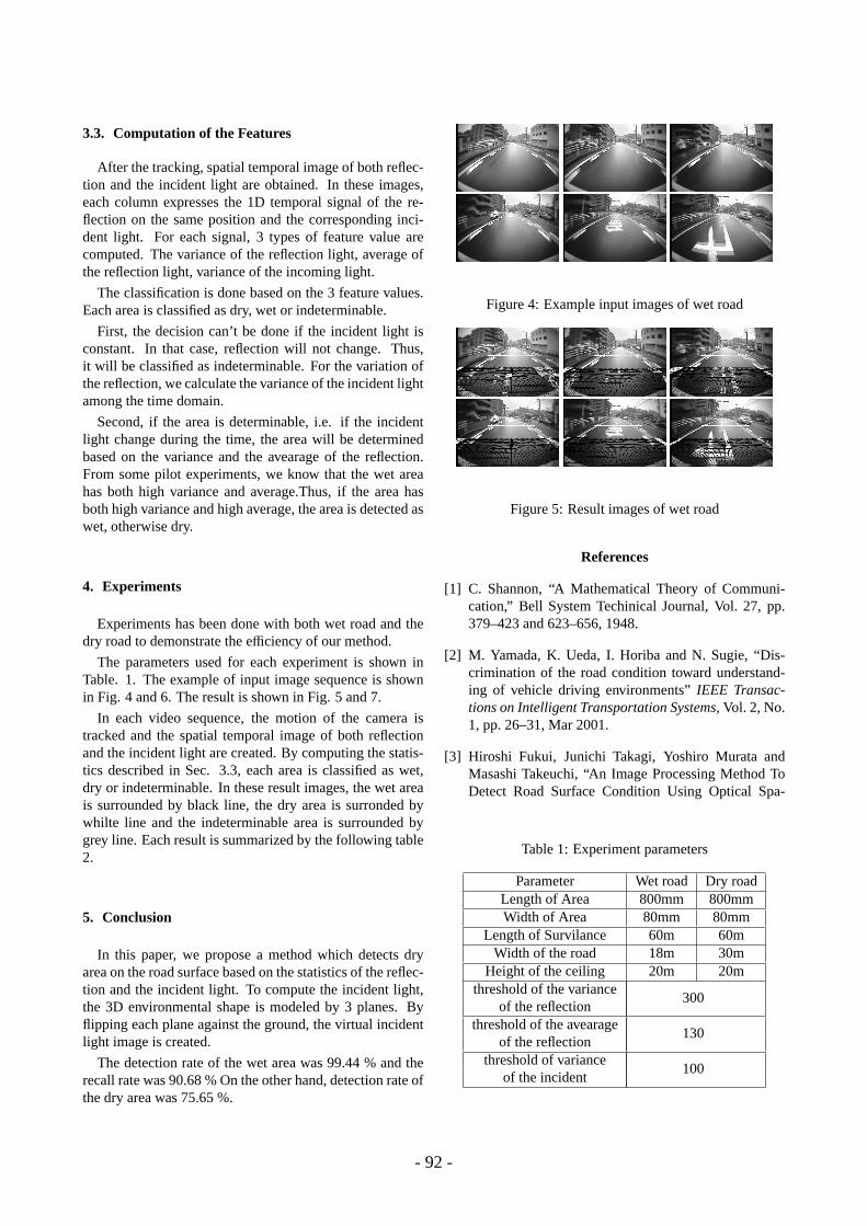
To compute the variance of the incident lights, we makea spatial temporal image of the incident light based on the3D environmental shape. In this paper, we do not estimatethe 3D environmental shape but assume that it can be mod-eled by 3 planes. Two walls, ground and the ceiling, asdescribed in Fig. 3 (a).
Figure 2: Spatial temporal image
Wall Left
Wall Right
Ceilin
g
(a) Modeled Shape
Wall Left Wall Right
Ceiling
(b) Input Image
Flipped Wall Left
Flipped Wall Right
Flippe
d
Ceilin
g
(c) Flipped Model
Flipped Wall Left
Flipped Ceiling
Flipped Wall Right
(d) Virtual IncidentLight Image
Figure 3: Input image and the incident light
First, each plane is projected in the input image by theknown camera parameters(Fig. 3(b)). Each model’s corre-sponding area in the image is preserved as a texture. Next,each plane is flipped against the ground and again projectedto the image as shown in Fig. 3 (c). On the image, texturemapping is done to the flipped moedl’s corresponding areaby the preserved texture. Then the image appears that theentire ground is made by a specular reflection material. Wecall this image “Virtual Incident Light Image”.
In Sec. 3.1, we tracked the pixel of the input image andmade the spatial temporal image of the reflection light. Bytracking the pixel of the virtual incident light image, we canhave the spatial temporal image of the incident light.
To assume the environmental shape as a plane, distancebetween the camera and the environment object is requiredto be long enough.
- 91 -
3.3. Computation of the Features
After the tracking, spatial temporal image of both reflec-tion and the incident light are obtained. In these images,each column expresses the 1D temporal signal of the re-flection on the same position and the corresponding inci-dent light. For each signal, 3 types of feature value arecomputed. The variance of the reflection light, average ofthe reflection light, variance of the incoming light.
The classification is done based on the 3 feature values.Each area is classified as dry, wet or indeterminable.
First, the decision can’t be done if the incident light isconstant. In that case, reflection will not change. Thus,it will be classified as indeterminable. For the variation ofthe reflection, we calculate the variance of the incident lightamong the time domain.
Second, if the area is determinable, i.e. if the incidentlight change during the time, the area will be determinedbased on the variance and the avearage of the reflection.From some pilot experiments, we know that the wet areahas both high variance and average.Thus, if the area hasboth high variance and high average, the area is detected aswet, otherwise dry.
4. Experiments
Experiments has been done with both wet road and thedry road to demonstrate the efficiency of our method.
The parameters used for each experiment is shown inTable. 1. The example of input image sequence is shownin Fig. 4 and 6. The result is shown in Fig. 5 and 7.
In each video sequence, the motion of the camera istracked and the spatial temporal image of both reflectionand the incident light are created. By computing the statis-tics described in Sec. 3.3, each area is classified as wet,dry or indeterminable. In these result images, the wet areais surrounded by black line, the dry area is surronded bywhilte line and the indeterminable area is surrounded bygrey line. Each result is summarized by the following table2.
5. Conclusion
In this paper, we propose a method which detects dryarea on the road surface based on the statistics of the reflec-tion and the incident light. To compute the incident light,the 3D environmental shape is modeled by 3 planes. Byflipping each plane against the ground, the virtual incidentlight image is created.
The detection rate of the wet area was 99.44 % and therecall rate was 90.68 % On the other hand, detection rate ofthe dry area was 75.65 %.
Figure 4: Example input images of wet road
Figure 5: Result images of wet road
References
[1] C. Shannon, “A Mathematical Theory of Communi-cation,” Bell System Techinical Journal, Vol. 27, pp.379–423 and 623–656, 1948.
[2] M. Yamada, K. Ueda, I. Horiba and N. Sugie, “Dis-crimination of the road condition toward understand-ing of vehicle driving environments”IEEE Transac-tions on Intelligent Transportation Systems, Vol. 2, No.1, pp. 26–31, Mar 2001.
Parameter Wet road Dry roadLength of Area 800mm 800mmWidth of Area 80mm 80mm
Length of Survilance 60m 60mWidth of the road 18m 30m
Height of the ceiling 20m 20mthreshold of the variance
300of the reflection
threshold of the avearage130
of the reflectionthreshold of variance
100of the incident
- 92 -
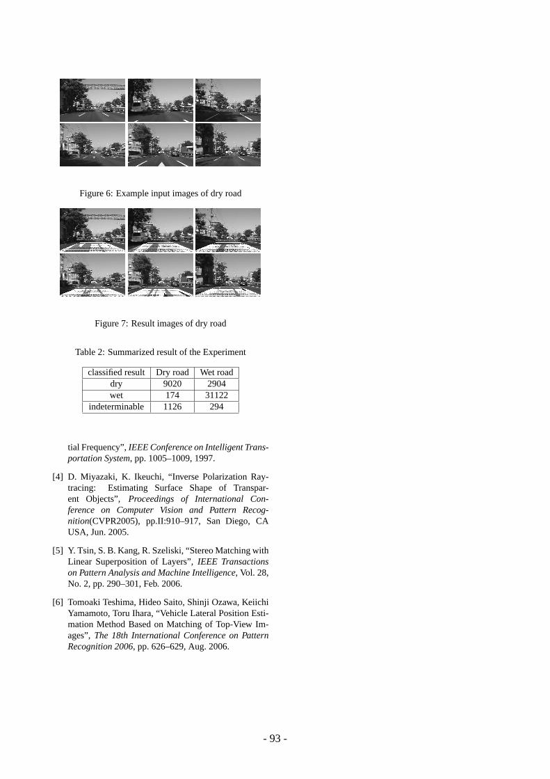
Figure 6: Example input images of dry road
Figure 7: Result images of dry road
Table 2: Summarized result of the Experiment
classified result Dry road Wet roaddry 9020 2904wet 174 31122
indeterminable 1126 294
tial Frequency”,IEEE Conference on Intelligent Trans-portation System, pp. 1005–1009, 1997.
[4] D. Miyazaki, K. Ikeuchi, “Inverse Polarization Ray-tracing: Estimating Surface Shape of Transpar-ent Objects”, Proceedings of International Con-ference on Computer Vision and Pattern Recog-nition(CVPR2005), pp.II:910–917, San Diego, CAUSA, Jun. 2005.
[5] Y. Tsin, S. B. Kang, R. Szeliski, “Stereo Matching withLinear Superposition of Layers”,IEEE Transactionson Pattern Analysis and Machine Intelligence, Vol. 28,No. 2, pp. 290–301, Feb. 2006.
[6] Tomoaki Teshima, Hideo Saito, Shinji Ozawa, KeiichiYamamoto, Toru Ihara, “Vehicle Lateral Position Esti-mation Method Based on Matching of Top-View Im-ages”,The 18th International Conference on PatternRecognition 2006, pp. 626–629, Aug. 2006.