Page 1
Wet etching technique for fabrication of GaSb based mid
infrared single lateral mode lasers
Seungyong Jung, Sergey Suchalkin, Leon Shterengas, Gela Kipshidze,
and Gregory Belenky
06.24.2011
Page 2
Outline
• Motivation
• Technology description
• Device fabrication
• Result and discussion
• Summary
Page 3
Applications of Mid IR Lasers
<Applications>- Gas detection- Free space communication- Medical diagnostics
<Schematic of the narrow ridge laser>
Absorption spectra of various gaseswithin Mid IR (2 ~ 5 µm) range
A. Krier et al, phys. stat. sol. (a) 205, No. 1, 129–143 (2008)
Page 4
Wide ridge vs. Narrow ridge lasers
Characteristics-Wide mesa width ~ 100 µm-High power -Lateral multimode operation-Relatively easy fabrication
Characteristics-Narrow mesa width < 10 µm-Low threshold-Lateral single mode operation-Relatively difficult fabrication-Necessary step for the longitudinal
single mode operation
Lateral direction
Transverse direction
< Wide ridge > < Narrow ridge >
Page 5
Crucial points to fabricate the narrow ridge
2. Etching depth control
1. WG width control
GaSb Substrate
Waveguide Cladding (p)AlGaAsSb
GradingCap: GaSb
Waveguide CoreInGaSb/AlGaAsSb
Waveguide Cladding (n)AlGaAsSb
< Typical GaSb based mid IR laser QW laser structure>
Lateral single mode requires the precise refractive index step (n1-n2) controltogether with the mesa width.0
n1n2 n2
Page 6
Fabrication of narrow ridge
<Dry etching>
Advantages Precise control of etching depth High degree of Directivity High degree of non-selective etching
Disadvantages High cost Low throughput
<Wet etching>
Advantages Cost effective High throughput Relatively easy implementationHigh degree of material selectivity
Disadvantages Low degree of directivity High degree of material selectivity
Could be preferred to industrial process.
Page 7
Implementation challenges using wet etching
Material selectivity Isotropic etching profile
< Etching test with Tartrate based solution>< Etching test with HCl based solution>
Fast etching rate for Al-rich material Fast etching rate for non Al-rich material
Al0.85GaAsSb
Al0.85GaAsSb
Page 8
Two major points of this technique
Etch Stopper
- Role:To control precise etching depth
- Requirement:1. Slow etching rate with HCl2. Need to minimize carrier
transport problem
Proper material selection
AlInGaAsSb
Complementary Etching
- Role:To compensate etching selectivitybetween the GaSb and AlGaAsSb layer.
- Procedure:1. Etching GaSb with Tartrate solution2. Etching AlGaAsSb with HCl solution
Page 9
Preliminary wet etching result
GaSb
AlGaAsSb
AlInGaAsSb(Stopper)
AlGaAsSb
<Etching test with the etch stopper>
Page 10
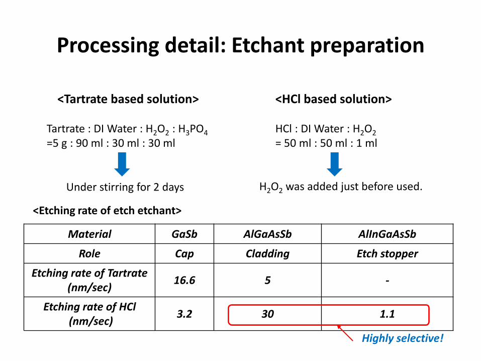
Processing detail: Etchant preparation
<Tartrate based solution>
Tartrate : DI Water : H2O2 : H3PO4
=5 g : 90 ml : 30 ml : 30 ml
Under stirring for 2 days
<HCl based solution>
HCl : DI Water : H2O2
= 50 ml : 50 ml : 1 ml
H2O2 was added just before used.
Material GaSb AlGaAsSb AlInGaAsSb
Role Cap Cladding Etch stopper
Etching rate of Tartrate (nm/sec)
16.6 5 -
Etching rate of HCl(nm/sec)
3.2 30 1.1
<Etching rate of etch etchant>
Highly selective!
Page 11
Processing detail: Etching Procedure
Etching cap+grading
Etchingthe p-clad
Metal layerGrading
GaSb
Cladding
Etch stop layer
<1. Metal deposition> <2. Etching with the Tartrate solution>
<3. Etching with the HCl solution><4. Photo-resist removal>
PR
PR
Page 12
Vertical wall narrow ridge with wet etching
Etch stopper
Si3N4
Metal alloyCap + Grading overhanging
1 µm
<Tartrate etching: 30 sec HCl etching: 30 sec>
< SEM image of the complete laser device>
Page 13
<4.2 um (12 μm) >
<2.4 μm (10 μm) > <0.5 μm (8 μm) >
Mesa width control
Various PR widthsPR
Page 14
Laser performance
RT cw power: ~70mW Far field at slow axis: ~8˚ (FWHM)
0.00 0.05 0.10 0.15 0.20 0.25 0.30 0.35 0.400
10
20
30
40
50
60
70
0.0
0.5
1.0
1.5
2.0
2.5
3.0
1.95 2.00 2.05 2.10
T=20oC, CW
730_S#1
coated(HR95%, AR5%)
L=2mm
Po
we
r (m
W)
Current (A)
Vo
lta
ge
(V
) Wavelength (m)
-20 -15 -10 -5 0 5 10 15 200.0
0.5
1.0
1.5
2.0
2.5
FWHM~9o
400mA
FWHM~8o
300mA
FWHM~7o
200mA
FWHM~7o
100mA
No
rma
lize
d I
nte
ns
ity
(a
. u
.)Angle(degree)
C730S#1, np5, AR/HR
6 m wide, 2mm long
7s, 10kHz, 20oC
Far field, slow axis
Page 15
Summary and Future work
<Summary>
• The lateral single mode laser has been fabricated by cost effective wet etching technique.
• Complementary etching with the etch stopper demonstrated effective mesa width and etching depth control.
• This technique can be used for sidewall smoothing, standing free 2D wire, etc. consisting of Al-rich and InGaAsSb sequential layers.
< Future work>
• Optimization of the etching process for precise etching control.
Sponsored by