Wet FGD Performance Upgrade Case Study at B.L. England Unit 2 Amy P. Evans Director of Technology Marsulex Environmental Technologies 200 North Seventh Street Lebanon, PA 17046 and Dennis Del Vecchio, PMP NAES Project Manager B.L. England Generating Station RC Cape May Holdings, LLC 900 North Shore Road Beesley’s Point, NJ 08223 and Gary M. Andes, P.E. Director, Air Quality Control WorleyParsons Group, Inc 2675 Morgantown Road Reading, Pennsylvania 19607 ABSTRACT RC Cape May Holdings LLC’s B.L. England Station Unit 2 was retrofitted with a limestone wet flue gas desulfurization system (FGD) that was placed in service in 1994 in order to comply with the 1990 Clean Air Act. An Administrative Consent Order (ACO) issued in 2006 by the New Jersey Department of Environmental Protection that required the SO 2 removal efficiency to be increased to 97% from the original performance level of ˜93% while firing the design 3.2% sulfur bituminous coal by May, 2010. WorleyParsons was retained as the plant’s architect engineer for the FGD upgrade project. After evaluation of various options, the technology selected to provide the performance upgrade
Transcript
Wet FGD Performance Upgrade Case Study at B.L. England Unit 2
Amy P. Evans Director of Technology
Marsulex Environmental Technologies 200 North Seventh Street
Lebanon, PA 17046 and
Dennis Del Vecchio, PMP NAES Project Manager
B.L. England Generating Station RC Cape May Holdings, LLC
900 North Shore Road Beesley’s Point, NJ 08223
and
Gary M. Andes, P.E. Director, Air Quality Control
WorleyParsons Group, Inc 2675 Morgantown Road
Reading, Pennsylvania 19607
ABSTRACT RC Cape May Holdings LLC’s B.L. England Station Unit 2 was retrofitted with a limestone wet flue gas desulfurization system (FGD) that was placed in service in 1994 in order to comply with the 1990 Clean Air Act. An Administrative Consent Order (ACO) issued in 2006 by the New Jersey Department of Environmental Protection that required the SO2 removal efficiency to be increased to 97% from the original performance level of ˜93% while firing the design 3.2% sulfur bituminous coal by May, 2010. WorleyParsons was retained as the plant’s architect engineer for the FGD upgrade project. After evaluation of various options, the technology selected to provide the performance upgrade
was the Absorber Liquid Redistribution Device (ALRD®), a patented and proprietary technology of Marsulex Environmental Technologies (MET), the OEM of the Unit 2 FGD system. In 2009, the project was initiated with the goal of meeting the more stringent SO2 emissions specified by the ACO of 0.150 lbs/MMBtu on a 30 day rolling average. This was accomplished without increasing slurry recirculation rate (L/G) and without adding noticeable FGD system pressure drop. The ALRD® technology is generally applicable to open spray tower wet FGD systems to mitigate the phenomena known as “sneakage” which represents a fractional part of the flue gas that passes only partially scrubbed near the FGD vessel wall, due to the physical limitations in the arrangement of the spray headers and nozzles near the circumference. Additionally, the ALRD® re-directs any absorber slurry that would otherwise to cling to, and run down, the tower wall back into the absorber spray zone, thus improving the usage of the re-circulated slurry. The modifications were incorporated into the Unit 2 FGD during two short outages in November 2009 and March 2010. This improvement was accomplished with a relatively simple retrofit having a negligible operational increase in pressure drop across the FGD tower. The results of the ALRD® installation at B.L. England exceeded expectations in improving SO2 removal efficiency over a broad range of operating conditions. This paper presents pertinent field data of the FGD from before and after the upgrade and reviews the implementation of the upgrade project. Introduction RC Cape May Holdings LLC (RCCMH) solicited proposals for a complete EPC package for the Unit 2 emissions control project in accordance with both the performance standards and schedule requirements of the Administrative Consent Order (ACO) issued by the New Jersey Department of Environmental Protection. The ACO required the reduction of SO2 to 0.150 lbs/MM Btu on a 30 day rolling average basis, and 0.250 lbs/MM Btu on a 24 hour emission rate by May 1, 2010. In order to meet the ACO SO2 limits, the existing scrubber SO2 removal efficiency had to be increased from the original 90-93% to 97% based on a 5.11 lb/mmBtu SO2 loading. RCCMH performed preliminary testing to determine the maximum efficiency that could be achieved by only revising the scrubber chemistry. The testing indicated that chemistry changes alone would not be sufficient to obtain the performance required. WorleyParsons, under contract to RCCMH, confirmed both physical and operational modifications would be necessary to achieve the specified reduction in SO2 emissions.
During the project feasibility stage, two options were explored prior to selecting the method to enhance SO2 removal. MET evaluated the ALRD technology as a candidate to improve the contact efficiency within the absorber, and WorleyParsons evaluated the more traditional approach of increasing the liquid in the “liquid to gas” equation by changing or modifying some system components. Increasing SO2 removal results in a higher sulfur inventory in the absorber reaction tank. A resulting design issue was how to maintain the necessary limestone dissolution, solids nucleation and crystal growth in the reaction tank with the additional SO2 processed by the absorber. MET and WorleyParsons agreed to utilize some of the reaction tank freeboard to allow an increase in reaction tank volume, and to also increase the slurry density (solids concentration) to subsequently increase the solids residence time without adding volume to the tank. WorleyParsons ran a process model to project the increase in liquid flow needed to achieve the lower SO2 emissions at maximum sulfur conditions. The options to increasing the liquid flow are to increase the existing pump capacity or operating more pumps at the expense of increasing absorber pressure drop. Upgrading the flow capacity of all four levels of recirculation pumps would have been expensive, incur a long lead time, a longer than desired outage time, and did not provide a sufficient increase in recirculation pump flow to reduce the SO2 emissions to the mandated levels while trying to reserve the fifth spray level as a spare. An alternate approach considered was to utilize all five absorber spray banks – including the spare level. This approach would increase the recycle flow by about 25%, as needed for reduced SO2 emissions. However, such a change in equipment redundancy would likely result in an unacceptable reduction in system availability. Load would have to be reduced in order to take individual pumps out of service for maintenance. Neither WorleyParsons or MET could recommend such a change in design basis and component/system operating philosophy. The first option of installing two ALRD levels was selected to meet the ACO requirements as the most cost and schedule effective approach for the matrix of operating conditions. Another benefit of this option was a negligible increase in system pressure drop, in contrast with the increased L/G option. The Unit 2 WFGD upgrade project was awarded to the team of WorleyParsons, MET and Nooter Construction Company in June 2009 based on installing the ALRD technology. WorleyParsons served as the architect engineer, MET served as the technology engineer/provider, and Nooter served as the erector. The project team reported to the B.L. England Project Manager.
Plant Description The RCCMH B.L. England Generating Station is located Upper Township, Cape May County, New Jersey, on the Great Egg Harbor River. The facility provides approximately 450 megawatts of generating capacity from three generating units. Two units burn coal and the third unit burns bunker C oil. Unit 2 is a balanced draft coal-fired boiler rated at 155 MW equipped with flue gas desulfurization, ESP, and NOx control. The primary fuel for the plant is eastern bituminous coal. The plant is currently operated by NAES Corporation, an independent O&M services provider located in Washington State. In 1994 Unit 2 was retrofitted with a carbon steel rubber lined wet FGD system. The flue gas from the boiler flows through induced draft fans and ductwork to a single open spray tower type absorber module. The treated gas is exhausted to atmosphere through a wet chimney. The system included a 100% capacity bypass duct for direct transfer of the flue gas from the ID fans to the chimney. . Performance Enhancements Design Basis The upgrade was designed to meet the reduced SO2 emissions of 0.15 lbs SO2/mmBtu. This emission rate translates to a removal efficiency requirement of 97 % removal at the design maximum inlet SO2 level of 5.11 lbs SO2/mmBtu. The performance coal is a 3.2 percent sulfur eastern bituminous coal with a heating value of 10,722 Btu/lb. Beyond the reduced SO2 emissions, other project technical requirements were to not adversely affect the particulate emissions or mist eliminator carryover from the absorber. Absorber Liquid Redistribution Device As shown in Illustration1 below, the ALRD technology is a device designed to modify the annular portion of the absorber total cross-sectional area near the absorber wall, and redirect the falling liquid film from the absorber wall back into the gas stream. This slight decrease in the cross-sectional area of the tower has a minimal effect on the flue gas pressure loss in the tower, but has a major effect on gas-liquid contact. One of the primary design criteria for achieving a desired level of SO2 reduction is the liquid-to-gas (L/G) ratio or the quantity of liquid sprayed relative to the volume of flue gas. Increasing the L/G ratio improves SO2 removal by exposing the gas to more absorbing liquor, but comes at the expense of higher power consumption. Installation of this device is an efficient method of improving the gas/liquid contact for an open spray tower. The ALRD technology was developed and patented (US Patent 6,550,751 B1) by MET in the 1990’s and is included in its OEM designs.
The ALRD technology additionally offsets the phenomena referred to as “sneakage” which represents the quantity of the flue gas that passes through the absorber partially untreated. Sneakage primarily occurs near the absorber wall due to the physical limitations in the arrangement of the spray headers and nozzles. This results in relatively low spray density concentrations at the circumference of the absorber.
Illustration 1: ALRD® Improvement in Gas-Liquid Contact near Absorber Wall
For new absorber tower designs, installation of the ALRD technology allows for a decrease in the number of spray levels in service for a given sulfur loading when compared to a design without the technology. This translates to a savings in both power consumption and materials through the decrease in the overall tower height, elimination of a spray level, and the associated absorber recycle pump. The ALRD technology has been commercially demonstrated in multiple FGD upgrades since 1997. Significant increases in SO2 removal efficiency have been achieved over a wide range of absorber diameters and geometries. Installed domestic upgrade capacity currently totals 18,674 MW at 26 installations including B.L. England.
Evaluation of Impacts to Process Equipment The B.L. England Unit 2 absorber was originally designed to operate with a recycle slurry density of 15 wt% solids. Under the revised operating conditions and improved SO2 removal efficiency, the concentration of solids in the recycle slurry increased to 18 - 20%, most of which is gypsum (CaSO4·2H2O). This density increase, together with the revised system inlet conditions and performance requirements could impact the duties of much of the existing process equipment. The evaluation of the existing equipment to meet the revised operating conditions indicated that none of the existing equipment required modification. The increase in the percentage of solids in the slurry and higher SO2 removal efficiency was within the capability of the absorber recycle pumps, absorber agitators, oxidation air compressors, bleed pumps, hydroclones and centrifuges. Implementation and Constructability Plan The implementation and constructability plan for the Absorber Liquid Re-Distribution (ALRD) Project presented several challenges. These challenges were mostly in the areas of communication and schedule constraints. The project needed to be completed during the scheduled maintenance outages. At BL England Generating Station there are typically two maintenance outages in a 12 month period. These are usually taken in the fall and spring months and last two and four weeks, respectively. Most Station maintenance work is scheduled for the spring outage and, hence, the longer time period. In addition, the success of the project depended largely on the communication and integration of work activities of seven separate entities. Figure 1 depicts the organization and reporting hierarchy for this project.
NAES/RCCMHBL England Station
Project ManagerDennis Del Vecchio
WorleyParsonsEngineering Design
Gary Andes
Nooter ConstructionEquipment Installation
ContractorTed GrunenwaldProject Manager
Marsulex EnvironmentalTechnologies
Equipment Supplier/Design SupportMike Hammer
Brand EnergyServices
Scaffold Contractors
BL England Generating StationALRD Installation
Project Organization Chart
ArboniteRubber Vulcanizing
Contractor
Figure 1
Local Union No. 28Boilermaker Workers
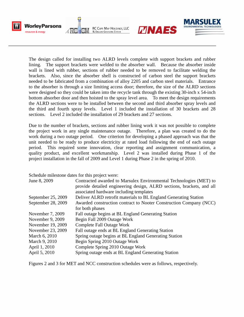
The design called for installing two ALRD levels complete with support brackets and rubber lining. The support brackets were welded to the absorber wall. Because the absorber inside wall is lined with rubber, sections of rubber needed to be removed to facilitate welding the brackets. Also, since the absorber shell is constructed of carbon steel the support brackets needed to be fabricated from a combination of alloy 2205 and carbon steel materials. Entrance to the absorber is through a size limiting access door; therefore, the size of the ALRD sections were designed so they could be taken into the recycle tank through the existing 30-inch x 54-inch bottom absorber door and then hoisted to the spray level area. To meet the design requirements the ALRD sections were to be installed between the second and third absorber spray levels and the third and fourth spray levels. Level 1 included the installation of 30 brackets and 28 sections. Level 2 included the installation of 29 brackets and 27 sections. Due to the number of brackets, sections and rubber lining work it was not possible to complete the project work in any single maintenance outage. Therefore, a plan was created to do the work during a two outage period. One criterion for developing a phased approach was that the unit needed to be ready to produce electricity at rated load following the end of each outage period. This required some innovation, clear reporting and assignment communication, a quality product, and excellent workmanship. Level 2 was installed during Phase 1 of the project installation in the fall of 2009 and Level 1 during Phase 2 in the spring of 2010. Schedule milestone dates for this project were: June 8, 2009 Contracted awarded to Marsulex Environmental Technologies (MET) to
provide detailed engineering design, ALRD sections, brackets, and all associated hardware including templates
September 25, 2009 Deliver ALRD retrofit materials to BL England Generating Station September 28, 2009 Awarded construction contract to Nooter Construction Company (NCC)
for both phases November 7, 2009 Fall outage begins at BL England Generating Station November 9, 2009 Begin Fall 2009 Outage Work November 19, 2009 Complete Fall Outage Work November 23, 2009 Fall outage ends at BL England Generating Station March 6, 2010 Spring outage begins at BL England Generating Station March 9, 2010 Begin Spring 2010 Outage Work April 1, 2010 Complete Spring 2010 Outage Work April 5, 2010 Spring outage ends at BL England Generating Station Figures 2 and 3 for MET and NCC construction schedules were as follows, respectively.
Figure 3, Nooter Construction Company Schedule for ALRD Implementation at B.L. England
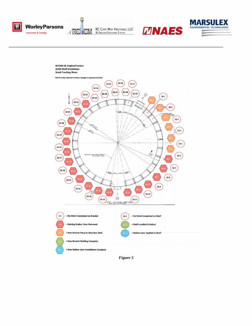
This project was completed in 10 months from initial contract award for material to closing the last man-way of the scrubber and ready to produce electricity. Due to the relatively short time period for completing each phase it was necessary for NCC to provide a daily report that efficiently describes the progress made each day. NCC needed to also show that the manpower they were employing was adequate to complete the work in the allotted time. Due to the confined space and the restrictions associated with working in a confined space there were manpower limitations; therefore, a perfect balance needed to be achieved. Figures 4, 5, 6, and 7 shows visually how the progress was recorded:
Figure 4
Figure 5
Figure 6
Figure 7
The reports were color coded to represent the level of achievement and also provided a quick reference illustration of work remaining to be completed. NCC provided this report daily. Although the referenced figures are for Phase 1 of the project the same tools were employed for Phase 2. Figures 8 and 9, following, were required of NCC to show the resource plan including number of skilled workers as well as a histogram of the work profile. BL England is a “Union Shop” and, therefore, all skilled labor was supported by the local union hall.
Figure 8
Figure 9
Another challenge of working in a confined space of an absorber is the care that had to be exercised in installing the scaffold. Structurally the spray nozzles at the two levels where the ALRD sections were to be installed were verified to be able to withstand the weight of scaffold and man loading. Since the absorber is exposed to highly caustic liquid vapors from the introduction of lime to the scrubber process all pipe headers and spray nozzles are rubber lined (as well as the entire inside of the absorber vessel). Installing the scaffold became a delicate activity because it was imperative that the headers the scaffold was secured to did not tear. The scaffold also needed to be placed in a way that allowed the ALRD sections to be installed without interference. In few instances some scaffold adjustment was required to permit access for welding. As previously mentioned some of the materials MET provided were three ALRD section templates. These were to be used as guides for trimming and cutting back the rubber for absorber wall access in the correct location for the brackets to be welded. The objective was to trim as little rubber as necessary. The brackets were pre-drilled, therefore, It was critical they were positioned correctly otherwise the bolt holes would not line up. These templates were constructed from stainless steel and weighed approximately 40 pounds. Handling to get them located in the proper position would have been cumbersome. This was especially true considering the confined work space. NCC recommended taking the templates to their fabricating facility to make exact replicas out of plywood. The weight was approximately 1/10 that of the stainless steel and made positioning and cutting much easier. This was an innovative approach and proved to save considerable time. The detailed execution plan for Phase 1 was developed after the milestones were provided to NCC by BL England. After review of these dates NCC proposed that one shift of five (5) days per week, working ten (10) hours per day would be sufficient to meet the fall 2009 milestones. However, it was considered that depending upon the productivity during the beginning of the fall 2009 outage, NCC may elect to work Saturday, November 14, 2009 or a periodic night shift. These provided a contingency plan should the risks associated with the installation and identified during the project risk assessment occur. For Phase 2 it was believed that the work could be accomplished with a single shift, five (5) days per week working eight (8) hours per day. For both Phases 1 and 2 the average direct boilermaker manpower was six (6) people. There was no issue acquiring qualified craftsmen for this project from the local union hall. During the fall 2009 outage, isolation and clean out of the absorber vessel was performed by BL England Plant Operations personnel on the first two (2) days of the outage. During this time NCC performed all their mobilization tasks, including site specific safety orientation, sign up, job set up, review Job Safety and Hazard Analyses (JSA and JHA), etc. When the vessel was ready the scaffold subcontractor Brand Energy Services, LLC began installing a perimeter work deck on the spray header at elevation 77’ – 1”. During Phase 1, twenty-nine (29) brackets and twenty-seven (27) ALRD sections were installed at this elevation. Structural calculations were performed to confirm the spray header was able to support the reaction load of the scaffold and
man loading. The scaffold was wired off in a manner that was safe yet would not harm the vessel rubber lining. The work area was lined with fire retardant blankets to ensure 100% spark containment. When the scaffold was complete the NCC Boilermakers “laid out” the removal of the rubber liner sections with Arbonite following right behind them and removing these sections. Arbonite Division of P & R Industries was the rubber vulcanizing subcontractor to NCC. All subcontractors were approved by the BL England Project Manager. As the liner sections were removed, NCC Boilermakers “laid out” on the vessel shell the location of the bracket attachments. To keep the work moving and in assembly line fashion the plan was to install the brackets while remaining layout work was performed. All shell to bracket welds was visually inspected by a Nooter certified weld inspector (CWI). Arbonite followed behind the NCC bracket installation to re-install the removed liner sections. During Phase 1 and due to the limited two week outage period, time did not permit Arbonite to compete vulcanizing the ALRD sections in the fall outage. This work was completed in the spring 2010 outage during Phase 2 of the project. Through Phase 1 all qualified control inspections were performed, NCC performed the final cleanout, the scaffold was removed and all man-ways were closed. Afterwards, the vessel was turned over to BL England Operations for startup. In the spring 2010 outage, isolation and cleanout of the absorber vessel was again provided by BL England Plant Operations personnel before the first days of the outage. As with Phase 1, this is the time NCC performed their mobilization tasks similar to those performed during Phase 1. BL England Project Manager and Plant personnel supported NCC as required and when needed. During this phase, scaffold was installed in a similar manner as with Phase 1 at the 72’-1” level. NCC Boilermakers installed thirty (30) brackets and twenty-eight (28) ALRD sections at this level. Because of their familiarity with the work and to maintain consistency Arbonite and Brand Energy Services were retained to perform the rubber vulcanizing work and scaffold installation. The same process was employed during Phase 2 of this project as was employed during Phase 1.
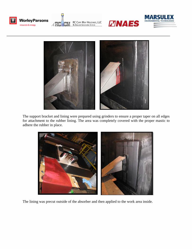
Installation Sequence The ALRD installation is detailed in the below photos.
The lay-out was marked on the existing rubber lining using a grease pencil and the rubber lining was stripped using a knife and an air hammer.
Once the rubber lining was removed from the interior of the absorber shell, the exposed carbon steel was cleaned with sanding wheels and the surface was prepped for welding. The support bracket was tack welded in place, fitted with one of the existing plates, and then final welded. Dilligent safety precautions included the use of fire blankets and a fire watch during the welding process.
The support bracket and lining were prepared using grinders to ensure a proper taper on all edges for attachment to the rubber lining. The area was completely covered with the proper mastic to adhere the rubber in place.
The lining was precut outside of the absorber and then applied to the work area inside.
All of the mounting brackets were installed before the rubber liner performed any vulcanizing work. The actual ALRD plate was used as a pattern to ensure a proper fit.
The plates were bolted in place before the top edge was vulcanized to the shell.
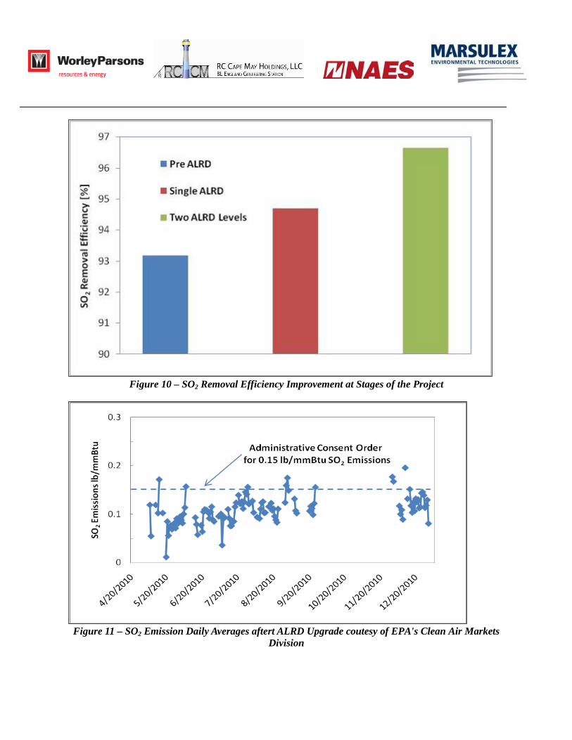
Installation Complete Performance Results Installation of the second level was completed several days before the May 1, 2010 deadline. With both levels in place, the system was able to successfully meet the state-required emissions limit. The system is now operated to maintain the required 0.15 lb SO2/mmBtu, instead of historical operation to maintain a system percentage removal efficiency. The system is capable of achieving 97%+ removal efficiency at the design 5.11 lb/mmBtu fuel; however, the system sulfur level is routinely less than the design level. The improvement in the SO2 removal efficiency measured over the span of the project is shown in Figure 10 based on data from the RCCMH Digital Control System (DCS). The removal efficiency after all the ALRD levels were installed is slightly less, on average, than 97% of the design as the system was operated to achieve the 0.15 SO2 lb/mmBtu requirement with lower than the design sulfur coal. The daily SO2 emissions data from the EPA's Clean Air Markets Division collected for the period after the ALRD installation shows that the Unit 2 emissions were typically less than the state-mandated level of 0.15 lb/mmBtu in Figure 11. Over the recorded period, the SO2 emissions averaged 0.11 lb/mmBtu and met the 30 day rolling average SO2 emissions ACO requirement of 0.150 lbs/MMBtu. The SO2 emissions trend contains periods when Unit 2 was off-line due to low power demand.
Figure 10 – SO2 Removal Efficiency Improvement at Stages of the Project
Figure 11 – SO2 Emission Daily Averages aftert ALRD Upgrade coutesy of EPA's Clean Air Markets
Division
Conclusions The installation of the ALRD technology at B.L. England successfully achieved the upgrade SO2 emissions target. The project implementation was well planned, well controlled and exhibited a well orchestrated effort by multiple suppliers. The plant was especially pleased that the 2,200+ hours of installation work, including welding in a rubber lined vessel, was completed without incident. Beyond the reduced SO2 emissions, other project technical requirements to not adversely affect the particulate emissions or mist eliminator carryover from the absorber were also met. The operating performance of the wet scrubber improvements at the B.L. England Station resulted in RCCMH waiving the performance tests. The ALRD installation has not impacted plant operation, maintenance, or availability nor has it had any measurable impact on the system pressure drop.


![[FGD I3M] Fgd pimnas + solusi](https://static.documents.pub/doc/80x56/558a2bccd8b42aca328b459a/fgd-i3m-fgd-pimnas-solusi.jpg)


