WG Dental Air Compressor William Green Operating instructions & Technical manual} WG Dental air compressor Page 1 of 18 Printed 24/10/2011, 12:21:03 PM Document Version 1.00 Operating Instructions & Technical manual WG Dental oil-less air compressor Document Version 1.01 – October 2100
Transcript
WG Dental Air Compressor
William Green Operating instructions & Technical manual} WG Dental air compressor
Page 1 of 18 Printed 24/10/2011, 12:21:03 PM Document Version 1.00
Operating Instructions & Technical manual WG Dental oil-less air compressor Document Version 1.01 – October 2100
WG Dental Air Compressor
William Green Operating instructions & Technical manual} WG Dental air compressor
Page 2 of 18 Printed 24/10/2011, 12:21:03 PM Document Version 1.00
Contents
1. Brief Introduction
2. Machine Structure
3. Main Technical Specification
4. Explanation of Marks
5. Transportation and Storage
6. Installation, Test and Operation
7. Maintenance
8. Notices
9. Troubleshooting
10. Accessories and Spare Parts
11. Electrical Circuit
12. Air Passage Drawing
13. The Drawing of The Compressor Structure (Version 1)
14. The Drawing of The Compressor Structure (Version 2)
15. The Drawing of The System
16. Appendix
WG Dental Air Compressor
William Green Operating instructions & Technical manual} WG Dental air compressor
Page 3 of 18 Printed 24/10/2011, 12:21:03 PM Document Version 1.00
1. Brief Introduction
WG air compressor features compact structure, stable performance, large flow rate, easy
operation and maintenance. Particularly the machine can be running without lubricant oil so
that the compressed air from the machine does not contain any oil fume; air can be obtained,
Because the air for dental apparatus must not contain any oil, this machine can be used as an
independent air supply machine for dental therapeutic apparatus; also can be used in other
areas such as medical care, scientific research, industrial production and daily life.
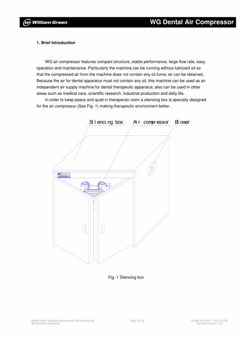
In order to keep peace and quiet in therapeutic room a silencing box is specially designed
for the air compressor (See Fig. 1) making therapeutic environment better.
3.请在消音箱两侧各留10cm空间,以保证消音箱内气流畅通。2.在使用过程中若遇到突然停电,应及时将压控开关切换至1.未接通消音箱排风扇电源,不得使用本空压机。注意Si l enci ng box Ai r compr essor Bl ower
Fig. 1 Silencing box
WG Dental Air Compressor
William Green Operating instructions & Technical manual} WG Dental air compressor
Page 4 of 18 Printed 24/10/2011, 12:21:03 PM Document Version 1.00
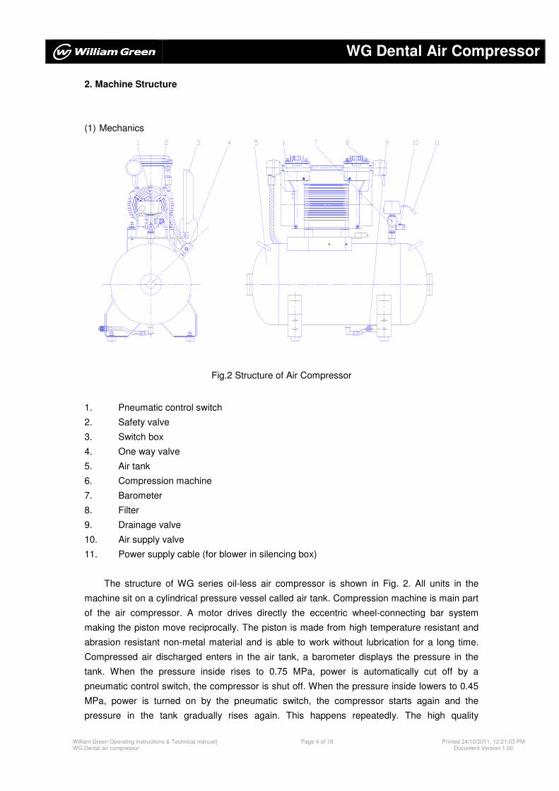
2. Machine Structure
(1) Mechanics
Fig.2 Structure of Air Compressor
1. Pneumatic control switch
2. Safety valve
3. Switch box
4. One way valve
5. Air tank
6. Compression machine
7. Barometer
8. Filter
9. Drainage valve
10. Air supply valve
11. Power supply cable (for blower in silencing box)
The structure of WG series oil-less air compressor is shown in Fig. 2. All units in the
machine sit on a cylindrical pressure vessel called air tank. Compression machine is main part
of the air compressor. A motor drives directly the eccentric wheel-connecting bar system
making the piston move reciprocally. The piston is made from high temperature resistant and
abrasion resistant non-metal material and is able to work without lubrication for a long time.
Compressed air discharged enters in the air tank, a barometer displays the pressure in the
tank. When the pressure inside rises to 0.75 MPa, power is automatically cut off by a
pneumatic control switch, the compressor is shut off. When the pressure inside lowers to 0.45
MPa, power is turned on by the pneumatic switch, the compressor starts again and the
pressure in the tank gradually rises again. This happens repeatedly. The high quality
WG Dental Air Compressor
William Green Operating instructions & Technical manual} WG Dental air compressor
Page 5 of 18 Printed 24/10/2011, 12:21:03 PM Document Version 1.00
compressed air can be supplied to dental therapeutic instrument. In addition air supply valve,
drainage valve, safety valve and electrical switch box are installed on the air tank.
WG series oil-less air compressor is classified as a single head. This compressor includes an
air drier in the machine.
The air passage in WG series air compressor is shown in Fig.8 (where dotted line is air-drying
system, it is an option and can be installed on request from customers).
(2) Electrical
WG series oil-less air compressor is equipped with switch box with starter inside. Each
head is equipped with one switch box. The electrical wiring for the functions like start
protection is shown in Fig. 7.
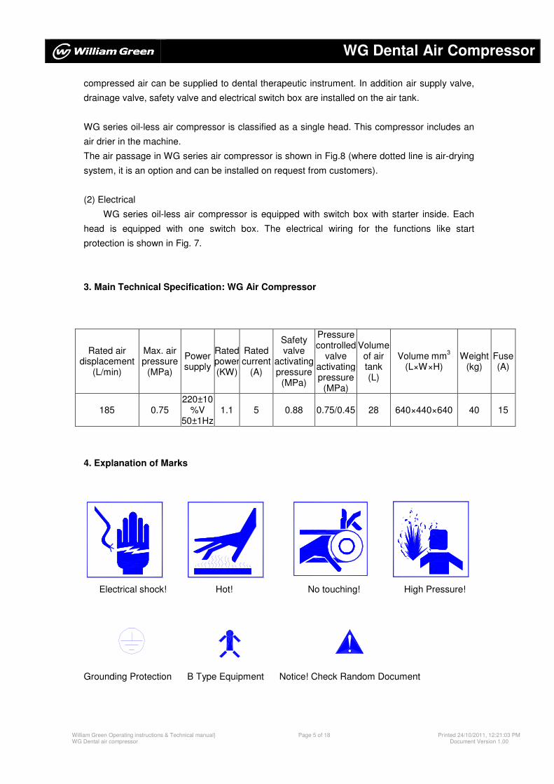
3. Main Technical Specification: WG Air Compressor
4. Explanation of Marks
Electrical shock! Hot! No touching! High Pressure!
Grounding Protection B Type Equipment Notice! Check Random Document
Rated air displacement
(L/min)
Max. air pressure
(MPa)
Power supply
Ratedpower (KW)
Rated current
(A)
Safety valve
activating pressure
(MPa)
Pressure controlled
valve activating pressure
(MPa)
Volume of air tank (L)
Volume mm3
(L×W×H) Weight
(kg) Fuse (A)
185 0.75 220±10
%V 50±1Hz
1.1 5 0.88 0.75/0.45 28 640×440×640 40 15
WG Dental Air Compressor
William Green Operating instructions & Technical manual} WG Dental air compressor
Page 6 of 18 Printed 24/10/2011, 12:21:03 PM Document Version 1.00
5. Transportation and Storage
The machine should be transported and stored in following condition:
Ambient temperature: -40�~55�
Relative humidity: ≤95%
Atmosphere pressure: 500HPa~1060HPa
6. Installation, Test and Operation
(1) Installation:
a. The machine should be operated in the room with temperature of 5~40 and relative
humidity of greater than 80% .Surrounding area of the machine should be clean, dry,
free of corrosive gas, well ventilated and no direct sunlight.
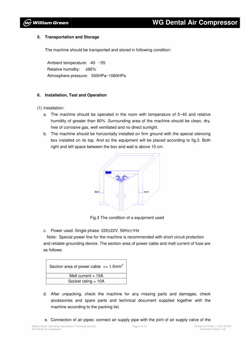
b. The machine should be horizontally installed on firm ground with the special silencing
box installed on its top. And so the equipment will be placed according to fig.3. Both
right and left space between the box and wall is above 10 cm. Not i ces 10cm10cm
Fig.3 The condition of a equipment used
c. Power used: Single phase: 220±22V, 50Hz±1Hz
Note: Special power line for the machine is recommended with short circuit protection
and reliable grounding device. The section area of power cable and melt current of fuse are
as follows:
Section area of power cable <= 1.5mm2
Melt current = 15A
Socket rating = 10A
d. After unpacking, check the machine for any missing parts and damages, check
accessories and spare parts and technical document supplied together with the
machine according to the packing list.
e. Connection of air pipes: connect air supply pipe with the joint of air supply valve of the
WG Dental Air Compressor
William Green Operating instructions & Technical manual} WG Dental air compressor
Page 7 of 18 Printed 24/10/2011, 12:21:03 PM Document Version 1.00
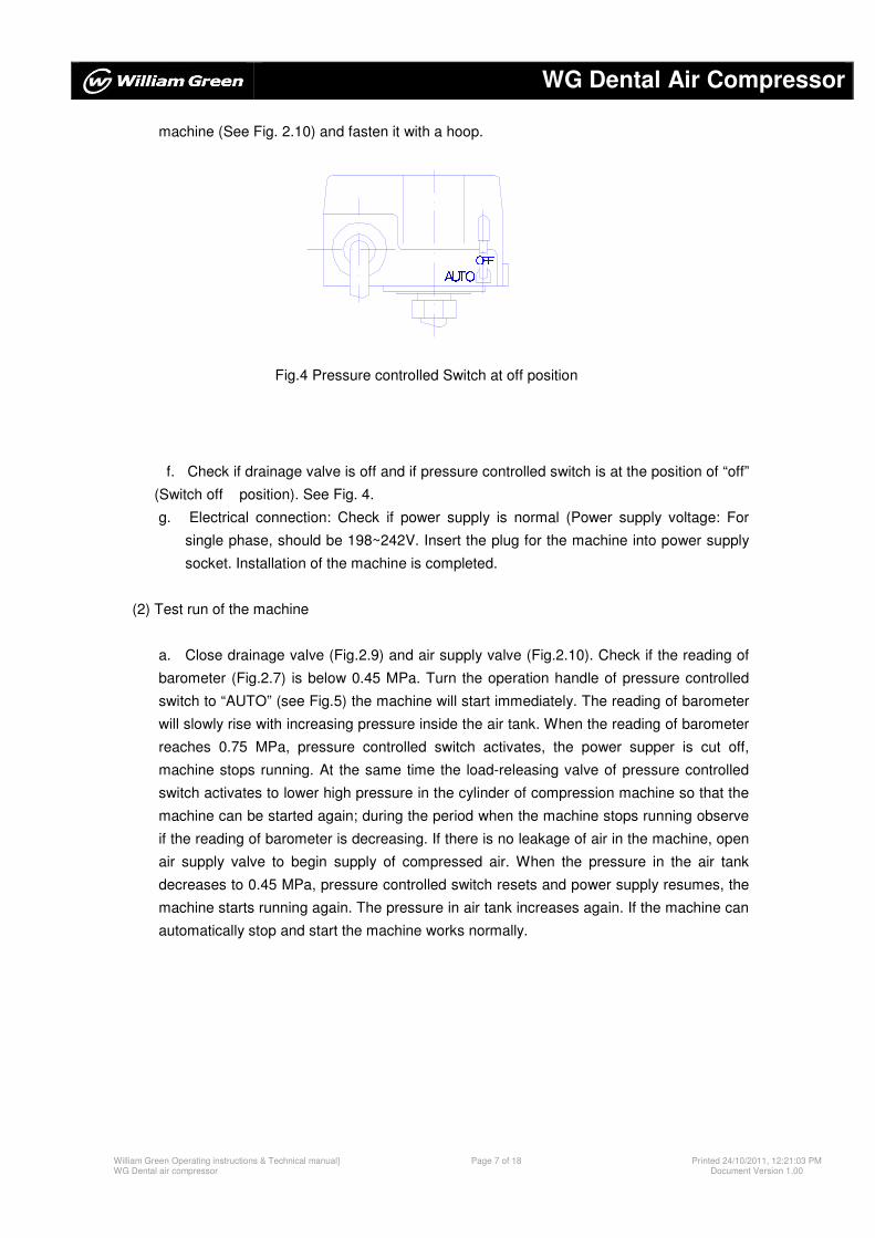
AUTOOFFmachine (See Fig. 2.10) and fasten it with a hoop.
Fig.4 Pressure controlled Switch at off position
f. Check if drainage valve is off and if pressure controlled switch is at the position of “off”
(Switch off position). See Fig. 4.
g. Electrical connection: Check if power supply is normal (Power supply voltage: For
single phase, should be 198~242V. Insert the plug for the machine into power supply
socket. Installation of the machine is completed.
(2) Test run of the machine
a. Close drainage valve (Fig.2.9) and air supply valve (Fig.2.10). Check if the reading of
barometer (Fig.2.7) is below 0.45 MPa. Turn the operation handle of pressure controlled
switch to “AUTO” (see Fig.5) the machine will start immediately. The reading of barometer
will slowly rise with increasing pressure inside the air tank. When the reading of barometer
reaches 0.75 MPa, pressure controlled switch activates, the power supper is cut off,
machine stops running. At the same time the load-releasing valve of pressure controlled
switch activates to lower high pressure in the cylinder of compression machine so that the
machine can be started again; during the period when the machine stops running observe
if the reading of barometer is decreasing. If there is no leakage of air in the machine, open
air supply valve to begin supply of compressed air. When the pressure in the air tank
decreases to 0.45 MPa, pressure controlled switch resets and power supply resumes, the
machine starts running again. The pressure in air tank increases again. If the machine can
automatically stop and start the machine works normally.
WG Dental Air Compressor
William Green Operating instructions & Technical manual} WG Dental air compressor
Page 8 of 18 Printed 24/10/2011, 12:21:03 PM Document Version 1.00
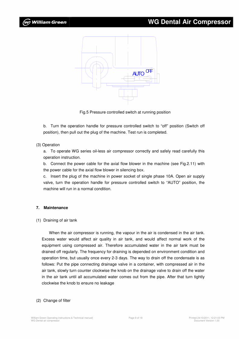
Fig.5 Pressure controlled switch at running position
b. Turn the operation handle for pressure controlled switch to “off” position (Switch off
position), then pull out the plug of the machine. Test run is completed.
(3) Operation
a. To operate WG series oil-less air compressor correctly and safely read carefully this
operation instruction.
b. Connect the power cable for the axial flow blower in the machine (see Fig.2.11) with
the power cable for the axial flow blower in silencing box.
c. Insert the plug of the machine in power socket of single phase 10A. Open air supply
valve, turn the operation handle for pressure controlled switch to “AUTO” position, the
machine will run in a normal condition.
7. Maintenance
(1) Draining of air tank
When the air compressor is running, the vapour in the air is condensed in the air tank.
Excess water would affect air quality in air tank, and would affect normal work of the
equipment using compressed air. Therefore accumulated water in the air tank must be
drained off regularly. The frequency for draining is depended on environment condition and
operation time, but usually once every 2-3 days. The way to drain off the condensate is as
follows: Put the pipe connecting drainage valve in a container, with compressed air in the
air tank, slowly turn counter clockwise the knob on the drainage valve to drain off the water
in the air tank until all accumulated water comes out from the pipe. After that turn tightly
clockwise the knob to ensure no leakage
(2) Change of filter
OFFAUTO
WG Dental Air Compressor
William Green Operating instructions & Technical manual} WG Dental air compressor
Page 9 of 18 Printed 24/10/2011, 12:21:03 PM Document Version 1.00
压力差设定 最高压力设定
增大 增大
An air filter is installed on air inlet of the air compressor (see Fig.2.8) to prevent the dust in the
air from entering the air compressor and reduce noise. After used for a period of time the filter
core in the air filter will get clogged. In a result sucking capacity of the air compressor will be
reduced, therefore the filter core must be replaced regularly. The way of replace is as follows:
open the lid on the air filter, take out the old filter core, put in a new one, then close the lid.
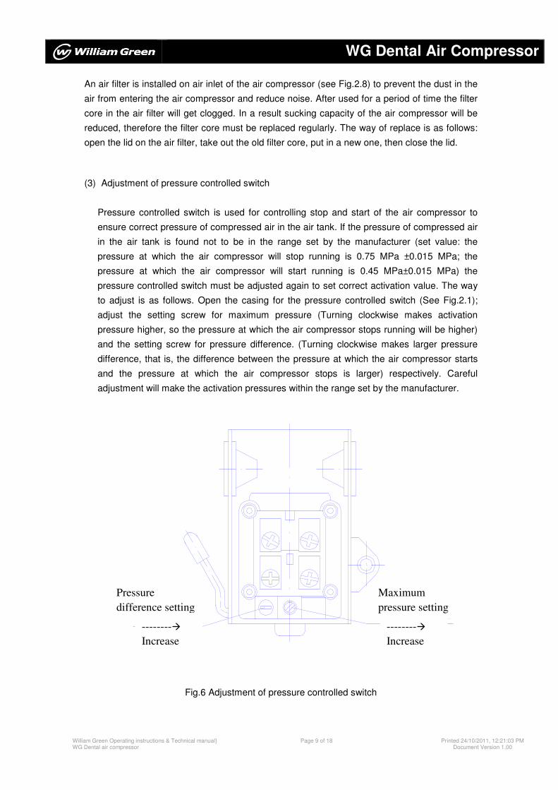
(3) Adjustment of pressure controlled switch
Pressure controlled switch is used for controlling stop and start of the air compressor to
ensure correct pressure of compressed air in the air tank. If the pressure of compressed air
in the air tank is found not to be in the range set by the manufacturer (set value: the
pressure at which the air compressor will stop running is 0.75 MPa ±0.015 MPa; the
pressure at which the air compressor will start running is 0.45 MPa±0.015 MPa) the
pressure controlled switch must be adjusted again to set correct activation value. The way
to adjust is as follows. Open the casing for the pressure controlled switch (See Fig.2.1);
adjust the setting screw for maximum pressure (Turning clockwise makes activation
pressure higher, so the pressure at which the air compressor stops running will be higher)
and the setting screw for pressure difference. (Turning clockwise makes larger pressure
difference, that is, the difference between the pressure at which the air compressor starts
and the pressure at which the air compressor stops is larger) respectively. Careful
adjustment will make the activation pressures within the range set by the manufacturer.
Fig.6 Adjustment of pressure controlled switch
Pressure
difference setting
--------�
Increase
Maximum
pressure setting
--------�
Increase
WG Dental Air Compressor
William Green Operating instructions & Technical manual} WG Dental air compressor
Page 10 of 18 Printed 24/10/2011, 12:21:03 PM Document Version 1.00
8. Notices
(1) The power supply for the machine is 220±22v and 50Hz single phase. To ensure the air
compressor working normally, for the machine using single phase power a voltage
stabiliser for single phase power must be provided.
(2) If power cut happens when the machine is running the operation handle of pressure
controlled switch should be turned to “off” position. When power supply resumes turn the
operation handle of the pressure controlled switch to “AUTO” position.
(3) Closely watch all safety mark to avoid injuries like scald, electrical shock etc.
(4) Drain off water in the air tank regularly and frequently brush off the dust on the radiator.
(5) Check the air filter regularly, replace filter core on time.
(6) Any trouble or failure should be checked and fixed by specialized technicians.
WG Dental Air Compressor
William Green Operating instructions & Technical manual} WG Dental air compressor
Page 11 of 18 Printed 24/10/2011, 12:21:03 PM Document Version 1.00
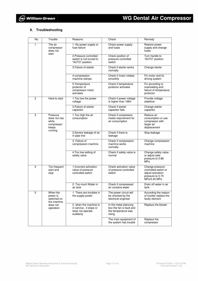
9. Troubleshooting
No. Trouble Reasons Check Remedy
1 The air compressor does not start
1. No power supply or fuse failure
Check power supply and fuses
Restore power supply and change fuses
2.Pressure controlled switch is not turned to “AUTO” position
Check position of pressure controlled switch
Turn handle to “AUTO” position
3.Failure of starter Check if starter works normally
Change starter
4.compression machine clamps
Check if motor rotates smoothly
Fix motor and its driving system
5.Temperature protector of compressor motor activates
Check if temperature protector activates
Fix according to overloading and failure of temperature protector
2 Hard to start 1.Too low the power voltage
Check if power voltage is higher than 198V
Provide voltage stabilizer
2.Failure of starter capacitor
Check if starter capacitor fails
Change starter capacitor
3 Pressure does not rise while compressor keeps running
1.Too high the air consumption
Check if compressor meets requirement for air consumption
Reduce air consumption or use compressor with larger air displacement
2.Severe leakage of air in pipe line
Check if there is leakage
Stop leakage
3. Failure of compression machine
Check if compression machine works normally
Change compression machine
4.Too low setting of safety valve
Check if safety valve is normal
Change safety value or adjust safe pressure to 0.88 MPa
4 Too frequent start and stop
1.Incorrect activation value of pressure controlled switch
Check activation value of pressure controlled switch
Change pressure controlled switch or adjust activation pressure to 0.75 MPa/0.45 MPa
2. Too much Water in air tank
Check if compressed air contains water
Drain off water in air tank
5 When the power is switched on the machine does not operation
1. There are troubles in the supply power
The power circuit will be checked by the electrical engineer
According the reason of trouble replace the faulty element
2. when the machine is in service , it stops or does not operate suddenly
In the metal silencing box the fan is fault and the temperature was rising
Replace the blower
The main equipment of the system has trouble
Replace the compressor
WG Dental Air Compressor
William Green Operating instructions & Technical manual} WG Dental air compressor
Page 12 of 18 Printed 24/10/2011, 12:21:03 PM Document Version 1.00
10. Accessories and Spare Parts
(1) Compressor system with single head
WG series φ8 PU pipe 3 (3m)
08-02 quick joint 1 set
φ8-G1/4 quick joint 1
G1/4�-G1/2 screw joint 1
(2) Fuses for WG 15A 2
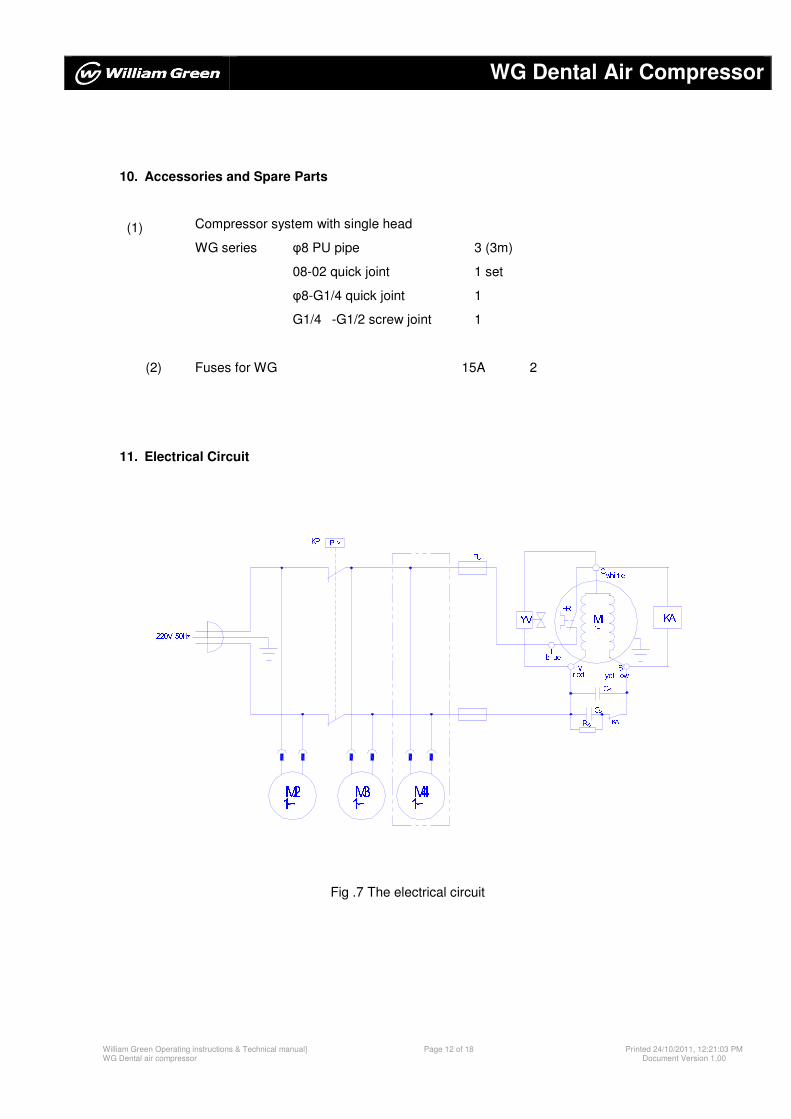
11. Electrical Circuit
1∽M2 1∽M3 ∽1M4220V 50HZ
PKP >RS SC KA
YVFU M1r ed Mbl ue L yel l ow RC S∽1FR Cwhi t e KA
Fig .7 The electrical circuit
WG Dental Air Compressor
William Green Operating instructions & Technical manual} WG Dental air compressor
Page 13 of 18 Printed 24/10/2011, 12:21:03 PM Document Version 1.00
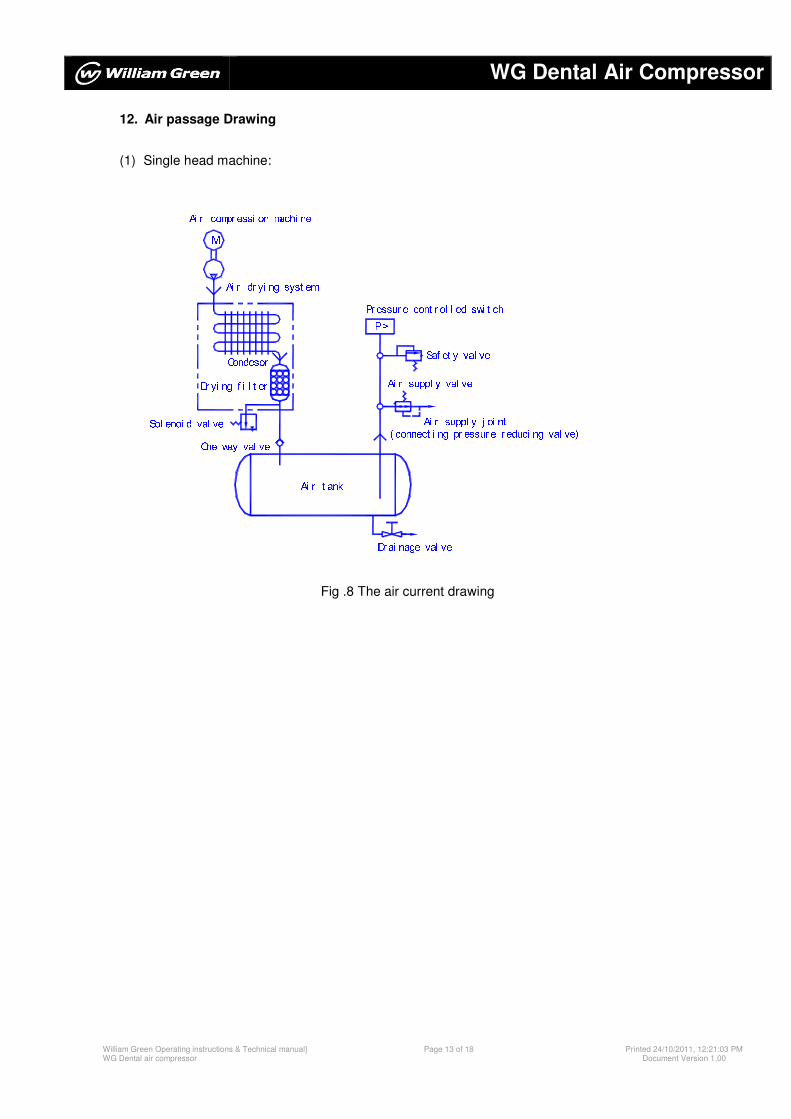
12. Air passage Drawing
(1) Single head machine:
One way val veDr ai nage val veAi r t ank
Ai r dr yi ng syst emDr yi ng f i l t erSol enoi d val ve Condesor
Ai r compr essi on machi neM Pr essur e cont r ol l ed swi t chSaf et y val ve( connect i ng pr essur e r educi ng val ve)Ai r suppl y j oi ntAi r suppl y val veP>
Fig .8 The air current drawing
WG Dental Air Compressor
William Green Operating instructions & Technical manual} WG Dental air compressor
Page 14 of 18 Printed 24/10/2011, 12:21:03 PM Document Version 1.00
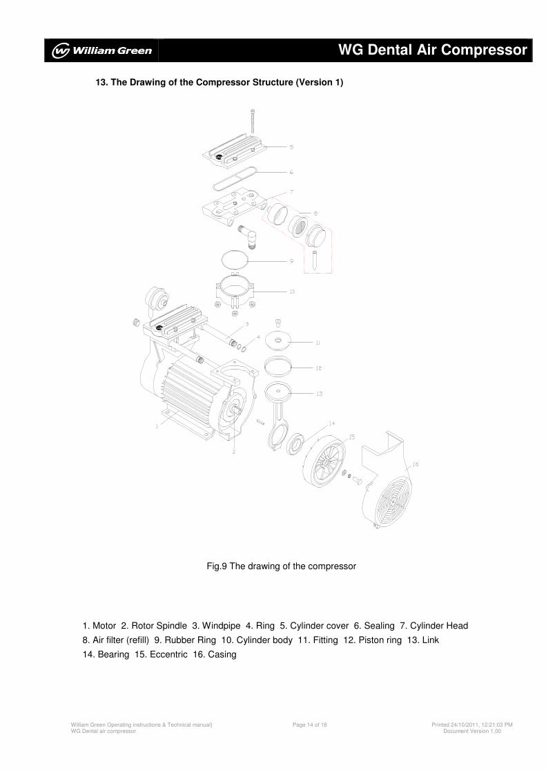
13. The Drawing of the Compressor Structure (Version 1)
Fig.9 The drawing of the compressor
1. Motor 2. Rotor Spindle 3. Windpipe 4. Ring 5. Cylinder cover 6. Sealing 7. Cylinder Head
8. Air filter (refill) 9. Rubber Ring 10. Cylinder body 11. Fitting 12. Piston ring 13. Link
14. Bearing 15. Eccentric 16. Casing
WG Dental Air Compressor
William Green Operating instructions & Technical manual} WG Dental air compressor
Page 15 of 18 Printed 24/10/2011, 12:21:03 PM Document Version 1.00
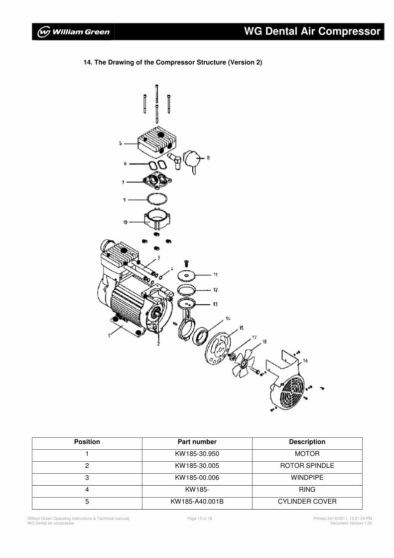
14. The Drawing of the Compressor Structure (Version 2)
Position Part number Description
1 KW185-30.950 MOTOR
2 KW185-30.005 ROTOR SPINDLE
3 KW185-00.006 WINDPIPE
4 KW185- RING
5 KW185-A40.001B CYLINDER COVER
WG Dental Air Compressor
William Green Operating instructions & Technical manual} WG Dental air compressor
Page 16 of 18 Printed 24/10/2011, 12:21:03 PM Document Version 1.00
6 KW185-A00.004 SEALING
7 KW185-A20.001 CYLINDER HEAD
8 KW185-00.008 AIR FILTER
9 KW185-00.003 RUBBER RING
10 KW185-00.005 CYLINDER BODY
11 KW185-10.001 FITTING
12 KW185-10.002 PISTON RING
13 KW185-10.003 LINK
14 KW185-NSK6009V BEARING
15 KW185-A00.001 ECCENTRIC
16 KW185-00.011 CASING
17 KW185-00.013 FAN CONNECT
18 KW185-00.012B FAN
WG Dental Air Compressor
William Green Operating instructions & Technical manual} WG Dental air compressor
Page 17 of 18 Printed 24/10/2011, 12:21:03 PM Document Version 1.00
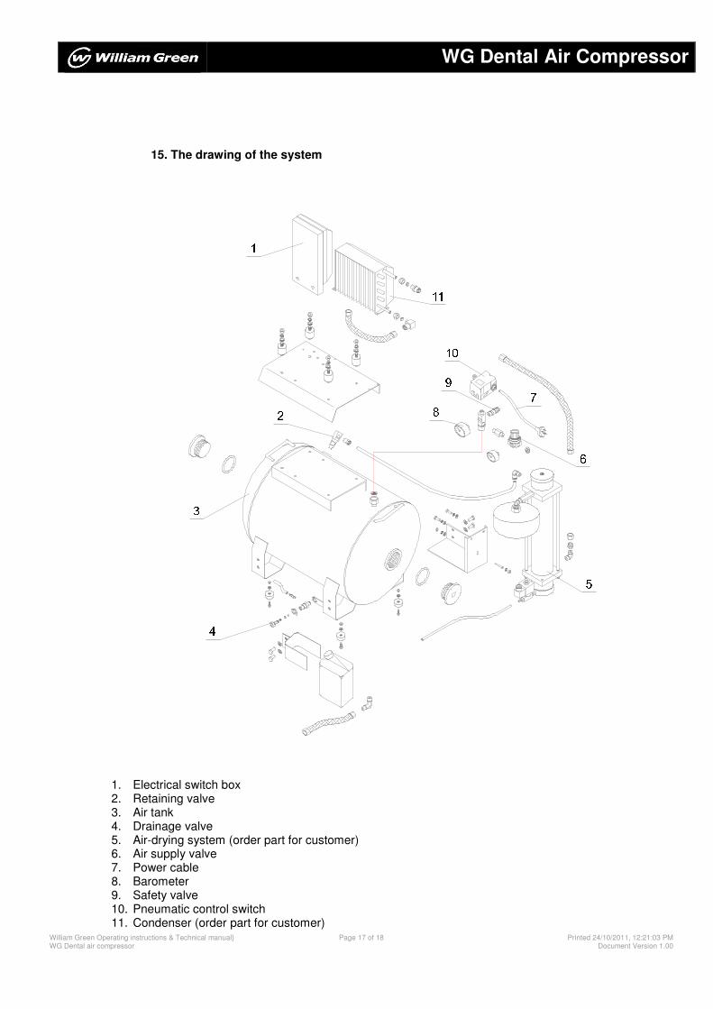
15. The drawing of the system
34 5
678 910111
2
1. Electrical switch box 2. Retaining valve 3. Air tank 4. Drainage valve 5. Air-drying system (order part for customer) 6. Air supply valve 7. Power cable 8. Barometer 9. Safety valve 10. Pneumatic control switch 11. Condenser (order part for customer)
WG Dental Air Compressor
William Green Operating instructions & Technical manual} WG Dental air compressor
Page 18 of 18 Printed 24/10/2011, 12:21:03 PM Document Version 1.00