12
®

®

What is a “Bubb-less Eliminator”?
The Bubb-less Eliminator will work effectively to remove bubbles from fluids in the following fluid samples: 1.Chemical Fluids
• Coating materials • Paint and ink • Chemical fluids • Polyethers, Polyvinyl alcohol, Ethylene glycol
2.Liquid foods 3.Industrial oils
• Engine oil • Gear oil • Turbine oil • Hydraulic oil
4.Biodegradable oil 5.Fire resistant oil
Answer: Bubbles cause various problems. “BUBB-less Eliminator”* can solve these problems.
Applications
*The Bubb-less Eliminator is manufactured by Opus Systems Inc., 3-25-20 Okusawa Seetagaya-ku, Tokyo 158-0083, Tokyo Japan.

Features (A) Installation of an Eliminator in the return line or processing line 1.Bubbles are removed from flowing fluids. 2.Various components, such as heaters, coolers, and filters can be incorporated in series. 3.The Eliminator can also be installed inside the reservoir to save space. (B) Installation in combination with a feed pump 1. If the flow system on the suction side of the pump is downstream of the Eliminator, then theoretically bubbles can be completely eliminated. By means of adjusting the rate of flow, the flow for the next processing flow for the next processing flow can be controlled. 2. If a throttle valve located on the pump suction side decreases the pressure between the throttle valve and pump, the capacity for the fluid may become over-saturated with dissolved gas. This will cause bubbles come out of the fluid on the pump suction side and flow into Eliminator where they can then be removed from the system. When the amount of dissolved gas is decreased, the rate of absorption of gas into the fluid will increase so that the fluid will adsorb more bubbles that dissolve into oil. (In some cases where chemical fluids are involved, this method may not suitable)
The Bubb-less Eliminator* is manufactured in four different configurations: standard type, in-line type, coater-type and the sanitary type designs to facilitate their installation and use in a wide variety of hydraulic circuits. These are illustrated in Figure 2 along with a schematic drawing of the inside geometry of each device.
Figure 1 – The Four Configurations of the “Bubble Eliminator” are A) standard, B) in-line, C) coater, and D) sanitary.
A B C D
*The Bubb-less Eliminator is manufactured by Opus Systems Inc., 3-25-20 Okusawa Seetagaya-ku, Tokyo 158-0083, Tokyo Japan.

Principles of Removing Bubbles
1) For given parameter for creating swirl, the Bubb-less Eliminator is consists of a tapered-tube that is designed such that a chamber of circular cross-section becomes smaller, then connected with a cylindrical straight tube chamber. Fluid containing bubbles flows tangentially into the tapered tube from an inlet port and generates a swirling flow that circulates the fluid through the flow passage.?
2) The swirling flow accelerates downstream, and the fluid pressure along the central axis decreases downstream. From the end of the tapered-tube, the swirl flow decelerates downstream and the pressure recovers toward the outlet.
3) There are certain position-dependent centrifugal forces created in all parts of the swirl flow, and the bubbles tend to move toward the central axis of the Eliminator due to the difference in centrifugal force. Small bubbles are trapped which makes an air column in the vicinity of central axis of the swirling flow near the area where the pressure is the lowest.
4) When back pressure is applied at the downstream side of the Bubb-less Eliminator, the collected bubbles will be ejected through the vent port.
There are certain position-dependent centrifugal forces created in all parts of the swirl flow, and the bubbles tend to move toward the central axis of the Bubble Eliminator due to the difference in centrifugal force. Small bubbles are trapped creating an air column in the vicinity of central axis of the swirling flow near the area where the pressure is the lowest. When backpressure is applied at the downstream side of the Bubble Eliminator, the collected bubbles will be ejected through the vent port. Figure 1 illustrates the air bubble removal ability of the Bubble Eliminator when used with a severely aerated hydraulic fluid.
Figure 2 – Example of air bubble removal, A) aerated fluid, B) de-aerated fluid.
A B
A schematic illustration of the operation of a Bubb-less Eliminator is produced in Figure 3.
Figure 3: Schematic illustration of the operation of a Bubb-less Eliminator
*The Bubb-less Eliminator is manufactured by Opus Systems Inc., 3-25-20 Okusawa Seetagaya-ku, Tokyo 158-0083, Tokyo Japan.

Standard Type Please note that these dimensions will be changed, in some cases, without previous notice. Dimensions will be confirmed before manufacturing by means of drawing for approval.
There is no upper limit for the flow rate.
Type Flow Rate l/min D H W
Port (Nominal mm)
Inlet Outlet Vent
BM- 10 10 49 135 35 15 15 6
BM- 30 30 76 200 52 25 20 8
BM- 60 60 76 220 58 32 25 8
BM-120 120 115 280 90 40 40 15
BM-180 180 140 300 100 50 50 15
BM-240 240 165 315 155 65 65 20
BM-330 330 165 315 155 65 65 20
BM-330 (Flow rate F330 l/min)
BC-16(left) (Material:Stainless Steel)
(Flow rate F16 l/min) BC-60(right)
(Material:Stainless Steel) (Flow rate F60 l/min)

There is no upper limit for the flow rate.
Type Flow Rate
(l/min) D L L 1 L 2 H W
Port (Nominal mm)
Inlet Outlet Vent
BM- 500 500 216 470 390 40 125 67 80 80 20
BM- 600 600 216 470 390 40 130 73 80 80 25
BM- 700 700 267 500 410 45 155 78 80 80 25
BM- 800 800 267 500 410 45 155 78 100 100 25
BM-1000 1000 267 500 410 45 155 78 100 100 25
BM-1200 1200 318 590 430 80 180 120 125 125 32
BM-1500 1500 318 590 430 80 180 120 150 150 32
BC-1500 (Material:Stainless Steel) (Flow rate� F1500 l/min)
In-Line Type Please note that these dimensions will be changed, in some cases, without previous notice. Dimensions will be confirmed before manufacturing by means of drawing for approval.
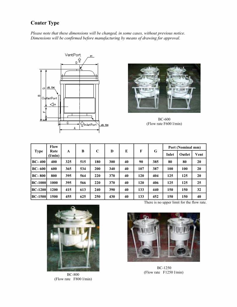
Coater Type Please note that these dimensions will be changed, in some cases, without previous notice. Dimensions will be confirmed before manufacturing by means of drawing for approval.
There is no upper limit for the flow rate.
Type Flow Rate
(l/min) A B C D E F G
Port (Nominal mm)
Inlet Outlet Vent
BC- 400 400 325 515 180 300 40 90 385 80 80 20
BC- 600 600 365 534 200 340 40 107 387 100 100 20
BC- 800 800 395 564 220 370 40 120 404 125 125 20
BC-1000 1000 395 566 220 370 40 120 406 125 125 25
BC-1200 1200 415 613 240 390 40 133 440 150 150 32
BC-1500 1500 455 625 250 430 40 133 452 150 150 40
BC-600 (Flow rate F600 l/min)
BC-800 (Flow rate� F800 l/min)
BC-1250 (Flow rate� F1250 l/min)
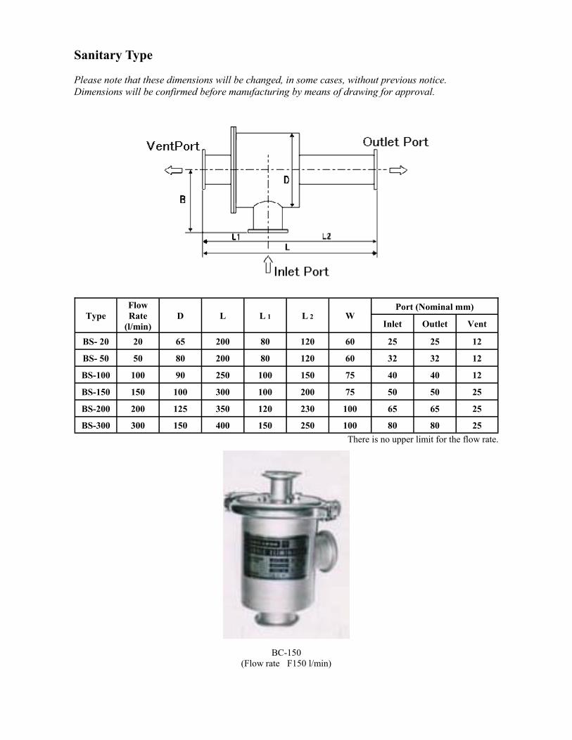
Sanitary Type Please note that these dimensions will be changed, in some cases, without previous notice. Dimensions will be confirmed before manufacturing by means of drawing for approval.
There is no upper limit for the flow rate.
Type Flow Rate
(l/min) D L L 1 L 2 W
Port (Nominal mm)
Inlet Outlet Vent
BS- 20 20 65 200 80 120 60 25 25 12
BS- 50 50 80 200 80 120 60 32 32 12
BS-100 100 90 250 100 150 75 40 40 12
BS-150 150 100 300 100 200 75 50 50 25
BS-200 200 125 350 120 230 100 65 65 25
BS-300 300 150 400 150 250 100 80 80 25
BC-150 (Flow rate� F150 l/min)

5 years ago, there was an air emulsion problem in the lubrication oil for turbo chargers of container carriers (tonnage 66,000 ton), newly designed and built by Mitsubishi Heavy industries. The lubrication oil became an air emulsion which was caused by the churning effect of bearing rotation. Bubbles in oil greatly influence the performance of lubrication system and may cause major problem such as degradation of lubrication, oil temperature rise, loss of oil and creation of sludge. Since then 25 Bubb-less Eliminators* (flow rate 660 L/min) have been used for the container carriers. The Bubb-less Eliminator* was installed in these circuits and the problem was solved by effectively removing the small bubbles from the fluid. (cf. Figure 4)
Due to the change of regulations in Japan, a manufacturer was requested to install various first-aid items to their fire engines with ladder. To create space in the fire engines for these items, they tried to use a smaller oil tank. If the oil does not reside in the tank long enough for the bubbles to reach the surface, the bubbles are drawn into the suction line and many problems occur. Then the Bubb-less Eliminator* was introduced to prevent air bubbles entrainment problem in the hydraulic oil systems. As a result bubble removed concrete benefits were obtained including, reduce oil temperature rise and noise reduction of the hydraulic pump. Seventeen Eliminators (flow rate 40-220 L/min) have been installed this for. The devices have been installed on the cover plate of oil tank to save space. (cf. Figure 5)
Case Histories
4
5 *The Bubb-less Eliminator is manufactured by Opus Systems Inc., 3-25-20 Okusawa Seetagaya-ku, Tokyo 158-0083, Tokyo Japan.
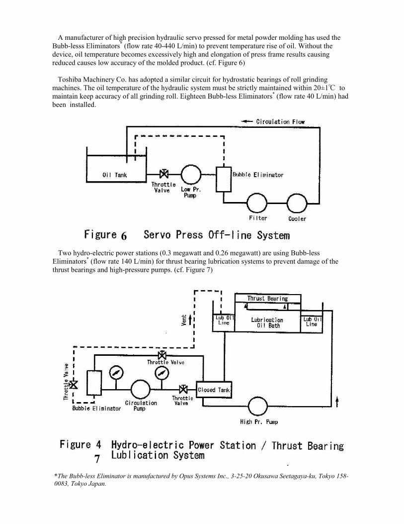
A manufacturer of high precision hydraulic servo pressed for metal powder molding has used the Bubb-lesss Eliminators* (flow rate 40-440 L/min) to prevent temperature rise of oil. Without the device, oil temperature becomes excessively high and elongation of press frame results causing reduced causes low accuracy of the molded product. (cf. Figure 6) Toshiba Machinery Co. has adopted a similar circuit for hydrostatic bearings of roll grinding machines. The oil temperature of the hydraulic system must be strictly maintained within 20±1℃ to maintain keep accuracy of all grinding roll. Eighteen Bubb-less Eliminators* (flow rate 40 L/min) had been installed.
Two hydro-electric power stations (0.3 megawatt and 0.26 megawatt) are using Bubb-less Eliminators* (flow rate 140 L/min) for thrust bearing lubrication systems to prevent damage of the thrust bearings and high-pressure pumps. (cf. Figure 7)
6
7 *The Bubb-less Eliminator is manufactured by Opus Systems Inc., 3-25-20 Okusawa Seetagaya-ku, Tokyo 158-0083, Tokyo Japan.

John Deere Product Engineering Center / Agricultural Engineering Hydraulic Core Technology evaluated the Bubb-less Eliminators*, and successful result was obtained. (cf. Figure 8)
Vickers Tedeco Division successfully evaluated the Bubb-less Eliminator (30 L/min) to the circuits shown in the Figure 9. Their deaeration performance data shows that the device is effective in removing entrained air from combined oil and air flows.
8
9 *The Bubb-less Eliminator is manufactured by Opus Systems Inc., 3-25-20 Okusawa Seetagaya-ku, Tokyo 158-0083, Tokyo Japan.

Figure 10 provides a basic circuit used by an oil hydraulic company in Japan for successfully evaluation of the Bubb-less Eliminators* for hydrostatic transmissions. (cf. Figure 10)
G.E. Totten & Associates, LLC P.O. Box 30108
Seattle, WA., 98103 U.S.A.
Tele: +1-206-788-0188 Fax: +1-815-461-7344
[email protected] www.getottenassociates.com
Please Contact G.E. Totten & Associates, LLC for more information on the Bubb-less Eliminator* Opus System’s at:
10
*The Bubb-less Eliminator is manufactured by Opus Systems Inc., 3-25-20 Okusawa Seetagaya-ku, Tokyo 158-0083, Tokyo Japan. Bubb-less Eliminator is a registered trademark of Opus Systems Inc. 3-25-20 Okusawa Sctagaya-ku, Tokyo 158-0083, Tokyo, Japan. Information contained in this publication is not to be taken as a warranty or representation for which G.E. Totten & Associates, LLC assumes legal responsibility. However, it remains at all times the responsibility of the customer to ensure that the materials described herein are suitable for the purpose for which they are intended by the customer. G.E. Totten & Associates, LLC accepts no liability whatsoever (except as otherwise provided by law) arising out of the use of the information supplied, the application, adaptation or processing of the products described herein.
Brochure design by DHx2 Media www.dhx2media.com


