12
BA receiver design Sonion Academy Introduction What is Balanced Armature Receiver Technology? November 2016 Rev_004

BA receiver design
Sonion Academy
Introduction
What is Balanced Armature Receiver Technology?
November 2016
Rev_004
Introduction to receivers
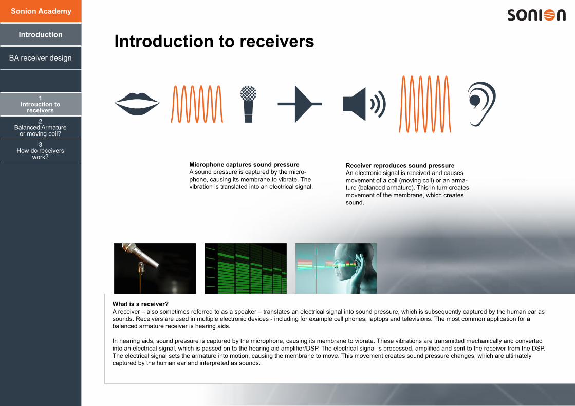
What is a receiver?A receiver – also sometimes referred to as a speaker – translates an electrical signal into sound pressure, which is subsequently captured by the human ear as sounds. Receivers are used in multiple electronic devices - including for example cell phones, laptops and televisions. The most common application for a balanced armature receiver is hearing aids.
In hearing aids, sound pressure is captured by the microphone, causing its membrane to vibrate. These vibrations are transmitted mechanically and converted into an electrical signal, which is passed on to the hearing aid amplifier/DSP. The electrical signal is processed, amplified and sent to the receiver from the DSP. The electrical signal sets the armature into motion, causing the membrane to move. This movement creates sound pressure changes, which are ultimately captured by the human ear and interpreted as sounds.
Receiver reproduces sound pressureAn electronic signal is received and causes movement of a coil (moving coil) or an arma-ture (balanced armature). This in turn creates movement of the membrane, which creates sound.
1Introuction to
receivers
3How do receivers
work?
2Balanced Armature
or moving coil?
BA receiver design
Introduction
Sonion Academy
Microphone captures sound pressureA sound pressure is captured by the micro-phone, causing its membrane to vibrate. The vibration is translated into an electrical signal.
1Introuction to
receivers
3How do receivers
work?
2Balanced Armature
or moving coil?
BA receiver design
Introduction
Sonion Academy
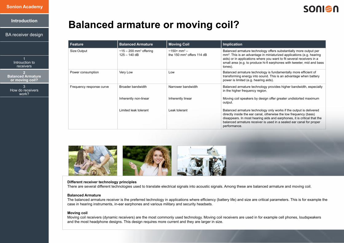
Feature Balanced Armature Moving Coil Implication
Size:Output ~15 – 200 mm3 offering 125 – 140 dB
~150+ mm3 – the 150 mm3 offers 114 dB
Balanced armature technology offers substantially more output per mm³. This is an advantage in miniaturized applications (e.g. hearing aids) or in applications where you want to fit several receivers in a small area (e.g. to produce hi-fi earphones with tweeter, mid and bass tones).
Power consumption Very Low Low Balanced armature technology is fundamentally more efficient of transforming energy into sound. This is an advantage when battery power is limited (e.g. hearing aids).
Frequency response curve Broader bandwidth
Inherently non-linear
Limited leak tolerant
Narrower bandwidth
Inherently linear
Leak tolerant
Balanced armature technology provides higher bandwidth, especially in the higher frequency region.
Moving coil speakers by design offer greater undistorted maximum output.
Balanced armature technology only works if the output is delivered directly inside the ear canal, otherwise the low frequency (bass) disappears. In most hearing aids and earphones, it is critical that the balanced armature receiver is used in a sealed ear canal for proper performance.
Balanced armature or moving coil?
Different receiver technology principlesThere are several different technologies used to translate electrical signals into acoustic signals. Among these are balanced armature and moving coil.
Balanced ArmatureThe balanced armature receiver is the preferred technology in applications where efficiency (battery life) and size are critical parameters. This is for example the case in hearing instruments, in-ear earphones and various military and security headsets.
Moving coilMoving coil receivers (dynamic receivers) are the most commonly used technology. Moving coil receivers are used in for example cell phones, loudspeakers and the most headphone designs. This design requires more current and they are larger in size.
2
3
4
1
1
5
6
Cover
Sound outlet
Membrane
Armature
Coil
Magnet house
Magnets
Drive pinCase
1Introuaction to
receivers
3How do receivers
work?
2Balanced Armature
or moving coil?
BA receiver design
Introduction
Sonion Academy
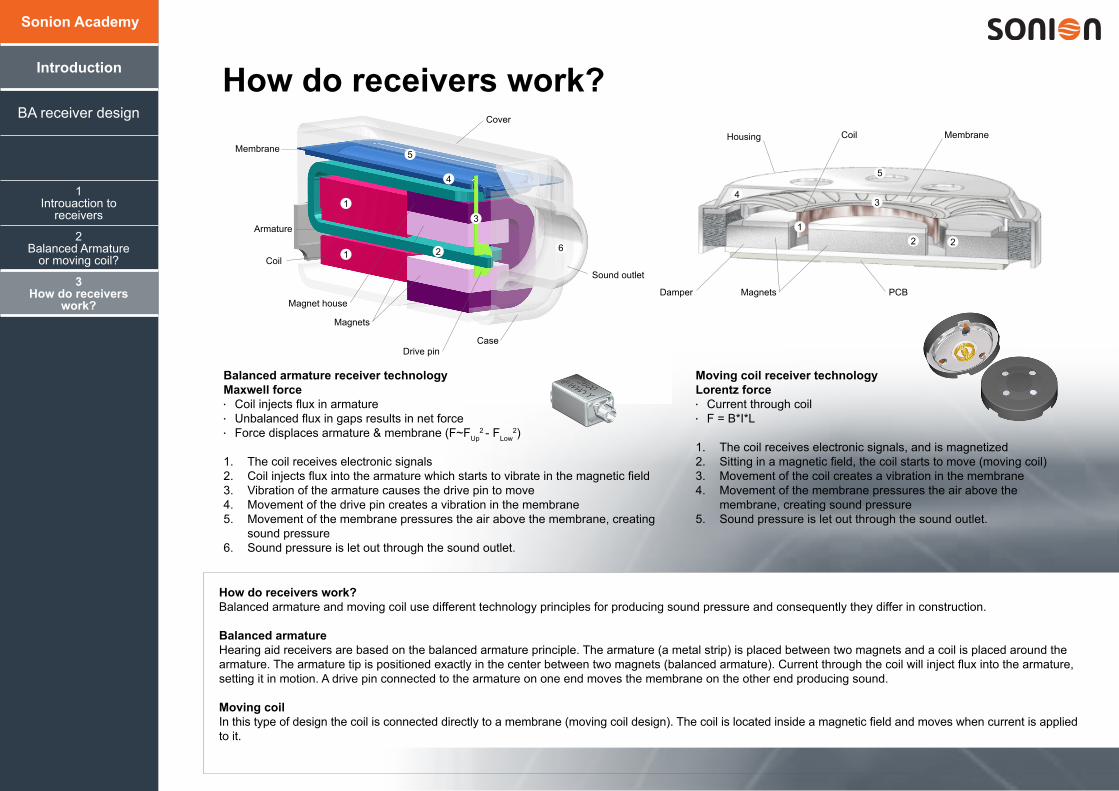
How do receivers work?
Moving coil receiver technologyLorentz force• Current through coil• F = B*I*L
1. The coil receives electronic signals, and is magnetized2. Sitting in a magnetic field, the coil starts to move (moving coil)3. Movement of the coil creates a vibration in the membrane4. Movement of the membrane pressures the air above the
membrane, creating sound pressure5. Sound pressure is let out through the sound outlet.
Balanced armature receiver technologyMaxwell force• Coil injects flux in armature• Unbalanced flux in gaps results in net force• Force displaces armature & membrane (F~FUp
2 - FLow2)
1. The coil receives electronic signals2. Coil injects flux into the armature which starts to vibrate in the magnetic field3. Vibration of the armature causes the drive pin to move4. Movement of the drive pin creates a vibration in the membrane5. Movement of the membrane pressures the air above the membrane, creating
sound pressure6. Sound pressure is let out through the sound outlet.
2 2
34
1
5
MembraneCoil
Magnets PCB
Housing
Damper
How do receivers work? Balanced armature and moving coil use different technology principles for producing sound pressure and consequently they differ in construction.
Balanced armatureHearing aid receivers are based on the balanced armature principle. The armature (a metal strip) is placed between two magnets and a coil is placed around the armature. The armature tip is positioned exactly in the center between two magnets (balanced armature). Current through the coil will inject flux into the armature, setting it in motion. A drive pin connected to the armature on one end moves the membrane on the other end producing sound.
Moving coilIn this type of design the coil is connected directly to a membrane (moving coil design). The coil is located inside a magnetic field and moves when current is applied to it.
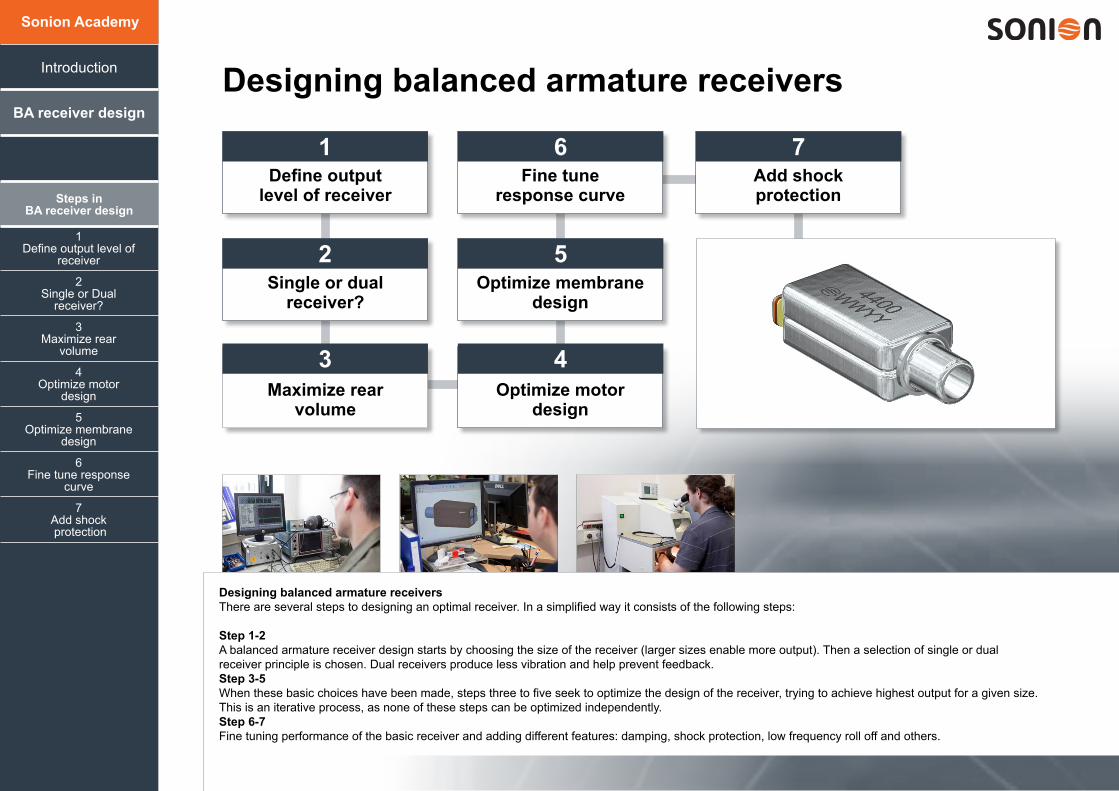
Designing balanced armature receivers
1Define output
level of receiver
1Fine tune
response curve
1Add shock protection
2Single or dual
receiver?
1Optimize membrane
design
3Maximize rear
volumeOptimize motor
design
1 6 7
2 5
3 4
1Define output level of
receiver
4Optimize motor
design
7Add shock protection
3Maximize rear
volume
6Fine tune response
curve
2Single or Dual
receiver?
5Optimize membrane
design
BA receiver design
Steps inBA receiver design
Introduction
Sonion Academy
Designing balanced armature receiversThere are several steps to designing an optimal receiver. In a simplified way it consists of the following steps:
Step 1-2 A balanced armature receiver design starts by choosing the size of the receiver (larger sizes enable more output). Then a selection of single or dual receiver principle is chosen. Dual receivers produce less vibration and help prevent feedback. Step 3-5 When these basic choices have been made, steps three to five seek to optimize the design of the receiver, trying to achieve highest output for a given size. This is an iterative process, as none of these steps can be optimized independently.Step 6-7 Fine tuning performance of the basic receiver and adding different features: damping, shock protection, low frequency roll off and others.
Step 1: Define target output
1Define output level of
receiver
4Optimize motor
design
7Add shock protection
3Maximize rear
volume
6Fine tune response
curve
2Single or Dual
receiver?
5Optimize membrane
design
BA receiver design
Introduction
Sonion Academy
95
100
105
110
115
120
125
130
135
10 100 1000Volume (mm3)
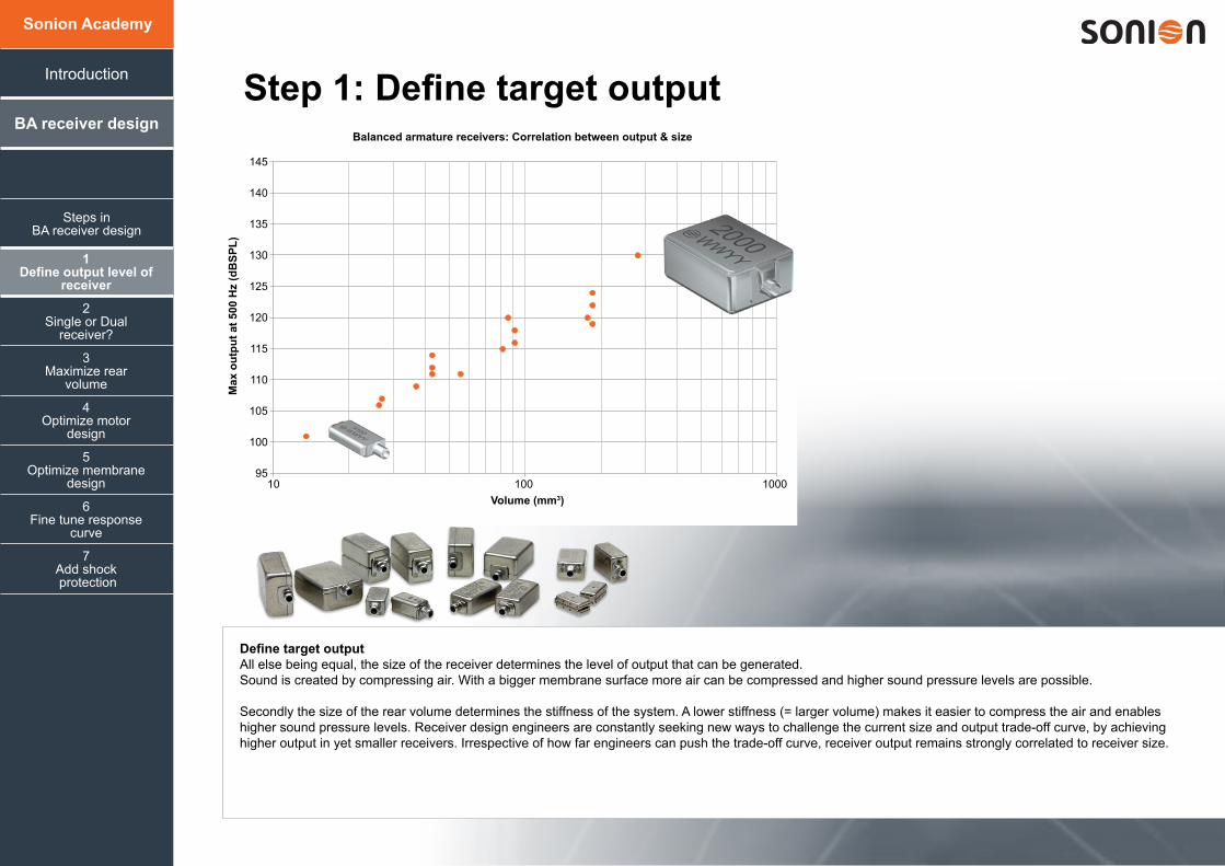
Balanced armature receivers: Correlation between output & size
Volume (mm3)
Max
out
put a
t 500
Hz
(dB
SPL)
10 100 1000
145
140
135
130
125
120
115
110
105
100
95
Steps inBA receiver design
Define target outputAll else being equal, the size of the receiver determines the level of output that can be generated. Sound is created by compressing air. With a bigger membrane surface more air can be compressed and higher sound pressure levels are possible.
Secondly the size of the rear volume determines the stiffness of the system. A lower stiffness (= larger volume) makes it easier to compress the air and enables higher sound pressure levels. Receiver design engineers are constantly seeking new ways to challenge the current size and output trade-off curve, by achieving higher output in yet smaller receivers. Irrespective of how far engineers can push the trade-off curve, receiver output remains strongly correlated to receiver size.
Step 2: Single or dual receiver?
1Define output level of
receiver
4Optimize motor
design
7Add shock protection
3Maximize rear
volume
6Fine tune response
curve
2Single or Dual
receiver?
5Optimize membrane
design
BA receiver design
Sonion Academy
Introduction
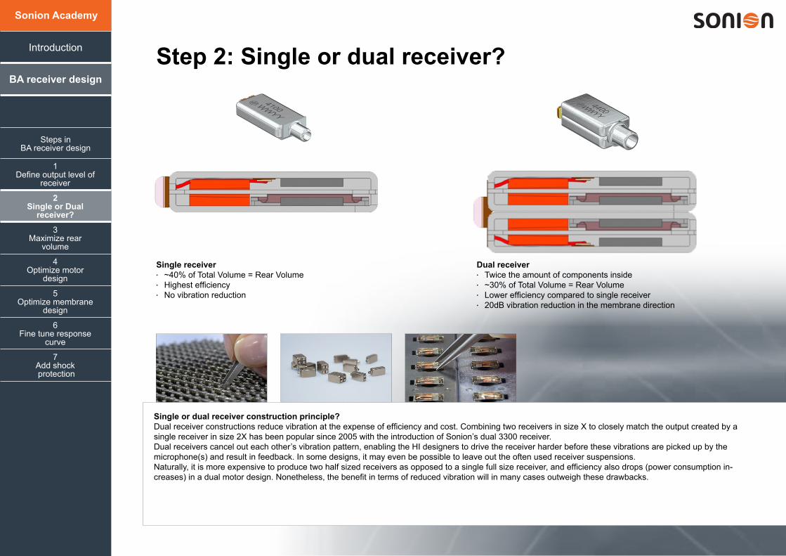
Single receiver• ~40% of Total Volume = Rear Volume • Highest efficiency• No vibration reduction
Dual receiver• Twice the amount of components inside• ~30% of Total Volume = Rear Volume• Lower efficiency compared to single receiver• 20dB vibration reduction in the membrane direction
Steps inBA receiver design
Single or dual receiver construction principle?Dual receiver constructions reduce vibration at the expense of efficiency and cost. Combining two receivers in size X to closely match the output created by a single receiver in size 2X has been popular since 2005 with the introduction of Sonion’s dual 3300 receiver. Dual receivers cancel out each other’s vibration pattern, enabling the HI designers to drive the receiver harder before these vibrations are picked up by the microphone(s) and result in feedback. In some designs, it may even be possible to leave out the often used receiver suspensions.Naturally, it is more expensive to produce two half sized receivers as opposed to a single full size receiver, and efficiency also drops (power consumption in-creases) in a dual motor design. Nonetheless, the benefit in terms of reduced vibration will in many cases outweigh these drawbacks.
70,0
80,0
90,0
100,0
110,0
120,0
130,0
100,0 1000,0 10000,0
Out
put (
dBSP
L)
Frequency (Hz)
Step 3: Maximize Rear Volume
1Define output level of
receiver
7Add shock protection
3Maximize rear
volume
6Fine tune response
curve
2Single or Dual
Receiver?
5Optimize membrane
design
BA Receiver Design
Introduction
Sonion Academy
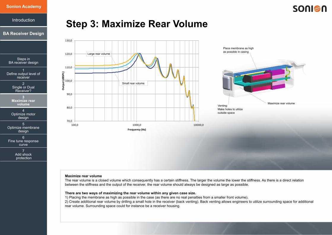
Place membrane as high as possible in casing
Venting: Make holes to utilize outside space
Maximize rear volume
Steps inBA receiver design
Large rear volume
Small rear volume
Maximize rear volumeThe rear volume is a closed volume which consequently has a certain stiffness. The larger the volume the lower the stiffness. As there is a direct relation between the stiffness and the output of the receiver, the rear volume should always be designed as large as possible.
There are two ways of maximizing the rear volume within any given case size.1) Placing the membrane as high as possible in the case (as there are no real penalties from a smaller front volume).2) Create additional rear volume by drilling a small hole in the receiver (back venting). Back venting allows engineers to utilize surrounding space for additional rear volume. Surrounding space could for instance be a receiver housing.
4Optimize motor
design
1Define output level of
receiver
4Optimize motor
design
7Add shock protection
3Maximize rear
volume
6Fine tune response
curve
2Single or Dual
receiver?
5Optimize membrane
design
BA receiver design
Introduction
Sonion Academy
Step 4: Optimize motor design - armature
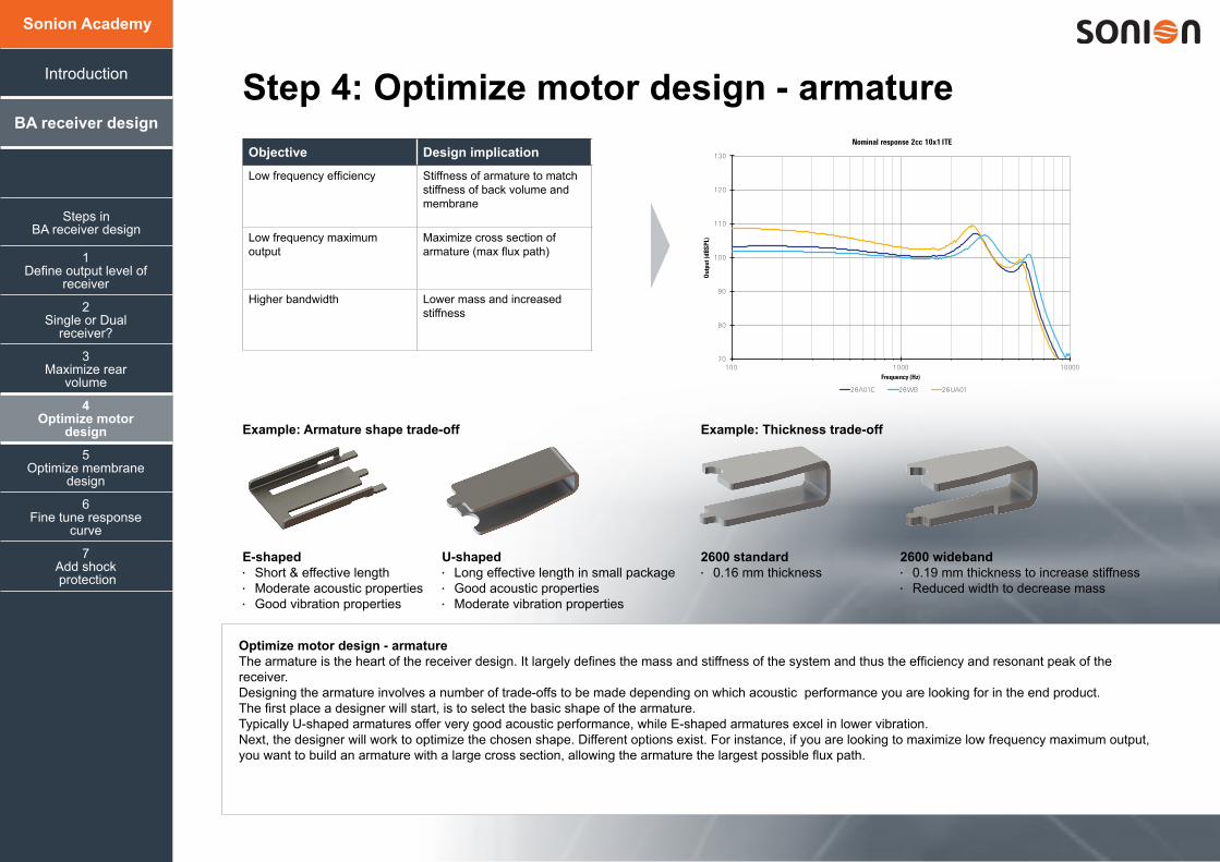
E-shaped• Short & effective length• Moderate acoustic properties• Good vibration properties
2600 standard• 0.16 mm thickness
U-shaped• Long effective length in small package• Good acoustic properties• Moderate vibration properties
2600 wideband• 0.19 mm thickness to increase stiffness• Reduced width to decrease mass
Example: Armature shape trade-off Example: Thickness trade-off
Steps inBA receiver design
Objective Design implication
Low frequency efficiency Stiffness of armature to match stiffness of back volume and membrane
Low frequency maximum output
Maximize cross section of armature (max flux path)
Higher bandwidth Lower mass and increased stiffness
Optimize motor design - armatureThe armature is the heart of the receiver design. It largely defines the mass and stiffness of the system and thus the efficiency and resonant peak of the receiver.Designing the armature involves a number of trade-offs to be made depending on which acoustic performance you are looking for in the end product. The first place a designer will start, is to select the basic shape of the armature. Typically U-shaped armatures offer very good acoustic performance, while E-shaped armatures excel in lower vibration. Next, the designer will work to optimize the chosen shape. Different options exist. For instance, if you are looking to maximize low frequency maximum output, you want to build an armature with a large cross section, allowing the armature the largest possible flux path.
70
80
90
100
110
120
130
100 1000 10000
Out
put (
dBSP
L)
Frequency (Hz)
Nominal response 2cc 10x1 ITE
26A01C 26WB 26UA01

1Define output level of
receiver
4Optimize motor
design
7Add shock protection
3Maximize rear
volume
6Fine tune response
curve
2Single or Dual
receiver?
5Optimize membrane
design
BA receiver design
Introduction
Sonion Academy
Step 5: Optimize membrane design
Placement Size Stiffness and mass Compensation gap(s)
Dividing front and back volume. Placement high in the casing will maximize back volume
Low frequency output.Larger size will move more air and consequently results in more output
High frequency output.With stiffness and mass the resonance peaks are deter-mined. Those could be optimized for use in ITE or BTE applications
Low frequency roll-off and damping of the second peak is created by adding compen-sation holes in membrane.
Steps inBA receiver design
Optimizing the membrane designThe membrane divides the front and the back volume of the receiver. It is the movement of the membrane which creates the pressure in the front volume, that ultimately generates sound.Apart from these basic functionalities, the membrane characteristics will also impact the ultimate sound performance of the receiver. While the size of the membrane determines the low frequency output of the receiver, the stiffness and mass determine the high frequency output. Compensation holes in the membrane determine the low frequency roll off.

Type I damping Type II damping Type III damping
Step 6: Fine tune response curve
1Define output level of
receiver
4Optimize motor
design
7Add shock protection
3Maximize rear
volume
6Fine tune response
curve
2Single or Dual
receiver?
5Optimize membrane
design
BA receiver design
Introduction
Sonion Academy
Compensation holes Compensation holes
Steps inBA receiver design
Damping screen Damping screen
80
85
90
95
100
105
110
115
100 1000 10000
Out
put (
dB S
PL)
Frequency (Hz)
2600 - standard response2600 - Type II damping
80
85
90
95
100
105
110
115
100 1000 10000
Out
put (
dB S
PL)
Frequency (Hz)
2600 - standard response2600 - Type III damping
80
85
90
95
100
105
110
115
100 1000 10000
Out
put (
dB S
PL)
Frequency (Hz)
2600 - standard response2600 - Type I damping
80
85
90
95
100
105
110
115
100 1000 10000O
utpu
t (dB
SPL
)Frequency (Hz)
2600 - standard response2600 - Type II damping
80
85
90
95
100
105
110
115
100 1000 10000
Out
put (
dB S
PL)
Frequency (Hz)
2600 - standard response2600 - Type III damping
80
85
90
95
100
105
110
115
100 1000 10000
Out
put (
dB S
PL)
Frequency (Hz)
2600 - standard response2600 - Type I damping 80
85
90
95
100
105
110
115
100 1000 10000
Out
put (
dB S
PL)
Frequency (Hz)
2600 - standard response2600 - Type II damping
80
85
90
95
100
105
110
115
100 1000 10000
Out
put (
dB S
PL)
Frequency (Hz)
2600 - standard response2600 - Type III damping
80
85
90
95
100
105
110
115
100 1000 10000
Out
put (
dB S
PL)
Frequency (Hz)
2600 - standard response2600 - Type I damping
Fine tune response curveBalanced armature receiver technology has a non-flat response curve. There are different ways of modifying the response curve in the final receiver design.The response curve of a receiver can be mechanically modified.Designers of hearing aids are interested in modifying the response curve because of the need to reduce feedback problems in the 4-6 kHz range. These modifications smooth the frequency response in these areas.Modifications are typically done internally or externally to the receiver. Internal modifications include adding compensation holes to the membrane, resulting in damping of the second peak. External modifications include a damping screen in the spout, resulting in damping of the first peak.
Step 7: Add shock protection
1Define output level of
receiver
4Optimize motor
design
3Maximize rear
volume
6Fine tune response
curve
2Single or Dual
receiver?
5Optimize membrane
design
BA receiver design
Introduction
Sonion Academy
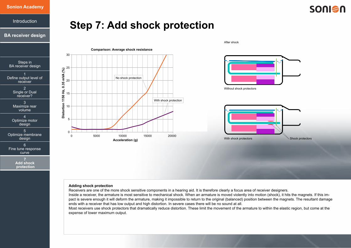
After shock
Without shock protectors
With shock protectors
7Add shock protection
0
5
10
15
20
25
30
0 5000 10000
Dis
torti
on 1
150H
z, 0
.35m
VA (%
)
Acceleration (g)
30
25
20
15
10
5
0
Comparison: Average shock resistance
Dis
tort
ion
1150
Hz,
0.3
5 m
VA (%
)
Acceleration (g)0 5000 10000 15000 20000
With shock protection
Shock protectors
No shock protection
Steps inBA receiver design
Adding shock protectionReceivers are one of the more shock sensitive components in a hearing aid. It is therefore clearly a focus area of receiver designers.Inside a receiver, the armature is most sensitive to mechanical shock. When an armature is moved violently into motion (shock), it hits the magnets. If this im-pact is severe enough it will deform the armature, making it impossible to return to the original (balanced) position between the magnets. The resultant damage ends with a receiver that has low output and high distortion. In severe cases there will be no sound at all. Most receivers use shock protectors that dramatically reduce distortion. These limit the movement of the armature to within the elastic region, but come at the expense of lower maximum output.


