48
Focused. Innovative. Responsive. What is Carbon Black? Focused. Innovative. Responsive. What is Carbon Black?

F o c u s e d. I n n o v a t i v e. R e s p o n s i v e.
What is Carbon Black?
F o c u s e d. I n n o v a t i v e. R e s p o n s i v e.
What is Carbon Black?


Contents
3
1 Introduction 4
1.1 About Orion Engineered Carbons 4
1.2 What is Carbon Black 7
2 Manufacturing Process 10
2.1 Raw Materials 12
2.2 Thermal-Oxidative Processes 14
2.2.1 Furnace Black Process 14
2.2.2 Degussa Gas Black Process 18
2.2.3 Lamp Black Process 19
2.2.4 Channel Black Process (historical) 20
2.3 Thermal Decomposition Processes 21
2.3.1 Thermal Black Process 21
2.3.2 Acetylene Black Process 22
2.4 Carbon Black Dispersions, Compounds,
Plastic and Rubber Masterbatches 23
3 Properties of Carbon Black 24
3.1 General Physical and Chemical Properties 25
3.2 Definition of Carbon Black 27
3.3 Test Methods, Chemical and Physical Data 28
3.3.1 Determination of Surface Area 32
3.3.2 Determination of Structure 33
3.3.3 Colorimetric Characterization 33
3.3.4 Chemical and Physical Measurements 34
3.3.5 Physical Appearance and Handling Properties 34
3.4 Specifications and Quality Assurance 35
3.5 Characteristic Data of various Production Processes 36
4 Handling 38
5 Product Safety 40
5.1 Toxicology 40
5.2 Safety-Related Properties 41
6 Applications 42
6.1 Rubber Carbon Blacks 42
6.2 Specialty Carbon Blacks 44
3
1 Introduction
Who We Are?
Orion Engineered Carbons (OEC) is one of the world’s leading suppliers of Carbon Black. We off er standard and high-performance products for coatings, printing inks, polymers, rubber and other applications. Our high-quality Gas Blacks, Furnace Blacks and Specialty Carbon Blacks tint, colorize and enhance the perfor-mance of plastics, paints and coatings, inks and toners, adhesives and sealants, tires, and manufactured rubber goods such as automotive belts and hoses.
With 1,360 employees worldwide, Orion Engineered Carbons runs 14 global production sites and 4 Applied Technology Centers, focusing on quality supply and collaborative partnerships with customers. Common shares of Orion Engineered Carbons are traded on the New York Stock Exchange under the symbol OEC.
Operational ExcellenceMarket and Technology-
Driven Product PortfolioReliable Partner Grow with Customers
Key Figures
Sales 2014 1.3 billion Euro
Number of Production Sites 14
Number of Technical Innovation Centers 4
Employees 1,360
Active in over 100 countries
Production Capacitiy p.a. 1.4 million t
Strategic Elements of our Mission
Our Vision
“We are the premium supplier of Carbon Black.
We generate long-term benefi ts for stakeholders while remaining committed to responsible
business practices with a focus on team culture, reliability and sustainability.”
1.1 About Orion Engineered Carbons
4

Locations
1) USA, Borger
Orion Engineered Carbons LLC9440 FM 1559, Hwy 136Borger, TX 79007, USA
2) USA, Kingwood (Regional Headquarters)
Orion Engineered Carbons LLC4501 Magnolia Cove DriveSuite 106Kingwood, TX 77345, USA
3) USA, Orange
Orion Engineered Carbons LLC1513 Echo RoadOrange, TX 77632, USA
4) USA, Belpre (Plant)
Orion Engineered Carbons LLC11135 State Route 7Belpre, OH 45714-9496, USA
4) USA, Belpre (Technical Center)
Orion Engineered Carbons LLC2730 Washington Blvd. Suite 2Belpre, OH 45714, USA
5) USA, Ivanhoe
Orion Engineered Carbons LLC7095 Highway 83Franklin, LA 70538, USA
6) Brazil, Paulínia
Orion Engineered Carbons Ltda.Av. Antonio Fadin, 1300Paulínia, SP, CEP 13147-030, Brazil
7) Brazil, São Paulo
Orion Engineered Carbons Ltda.R. Maestro Cardin, 1293São Paulo, SP, 01323-001, Brazil
8) Luxembourg
(Global Corporate Headquarters)
Orion Engineered Carbons S.A.6 Route de Trèves2633 Senningerberg, Luxembourg
9) France, Ambès
Orion Engineered Carbons SASLieu Dit Saint VincentBP 3, 33810 Ambès, France
10) Germany, Frankfurt (Global Operational
and Administrative Headquarters)
Orion Engineered Carbons GmbHHahnstraße 4960528 Frankfurt a.M., Germany
11) Germany, Cologne
(Plant and Technical Center)
Orion Engineered Carbons GmbHHarry-Kloepfer-Straße 150997 Cologne, Germany
12) Germany, Dortmund
Deutsche Gasrußwerke GmbH & Co KGWeidenstraße 70-7244147 Dortmund, Germany
13) Sweden, Malmö
Norcarb Engineered Carbons ABKusthamnsgatan 1211 24 Malmö, Sweden
14) Poland, Jaslo
Orion Engineered Carbons Sp. z o.o.83 3-go Maja Street38-200 Jaslo, Poland
15) Italy, Ravenna
Orion Engineered Carbons S.r.l.Via Baiona 17048123 Ravenna, Italy
16) South Africa, Port Elizabeth
Orion Engineered Carbons PTY (LTD)John Tallant Road6000 Port Elizabeth, South Africa
17) Korea, Bupyeong
(Plant and Technical Center)
Orion Engineered Carbons Co., Ltd.94, Galsan 1-Dong, Bupyeong-guIncheon, 403-081, South Korea
18) Korea, Yeosu
Orion Engineered Carbons Korea Co., Ltd.350, Wollae-dongYeosu-si, Jeollanam-do, 555-260, South Korea
19) Japan, Tokyo
Orion Engineered Carbons KKHolland Hills Mori Tower 16F5-11-2, Toranomon, Minato-Ku,Tokyo 105-0001, Japan
20) China, Shanghai
(Regional Headquarters)
Orion Engineered Carbons Trading (Shanghai) Co., Ltd.Room 3701-3702BM Intercontinental Business Centre100 Yutong Road200070 Shanghai, China
20) China, Shanghai (Technical Center)
Orion Engineered Carbons MaterialTechnology (Shanghai) Co., Ltd. Room 501-503 Building 1, Shanghai Juke Biotech Park No. 466 Yindu Road, Xuhui District200231 Shanghai, China
5

July 2014Common shares of Orion Engineered
Carbons are traded on the New York Stock Exchange under the symbol OEC
2011 - 2014 Orion Engineered
Carbons Operates as Standalone
Business
2013Orion completes conversion of lines at
Malmö (Sweden) and Belpre (Ohio, USA) to Specialty Carbon Black production
2013Orion installs a new Rubber Carbon Black
production line in Yeosu (South Korea)
September 2012Orion begins reorganization and refocusing
of R & D and product development to ex-pand its position as a leader in innovation
2010Evonik converts rubber lines into mainly
Specialty Carbon Black production at Belpre (Ohio, USA) and Malmö (Sweden)
2009Evonik converts rubber line into Specialty
Carbon Black
2011Evonik aquires full ownership of Algorax
Port Elizabeth (South Africa) Joint Venture
2007Evonik buys out Engineered Carbons Joint
Venture partner in North America
2002Degussa forms a Joint Venture with
Engineered Carbons in the USA, adding three plants in Texas, USA (Baytown,
Borger and Orange). Paulinia plant (greenfi eld) in Brazil starts
operations
1994Degussa forms the fi rst Western/Chinese Joint venture in the fi eld of Carbon Black
in Jiaozhou (China)
1988Plants acquired in Ivanhoe (Louisiana,
USA), Aransas Pass (Texas, USA) and Belpre (Ohio, USA)
1958Start of Furnace Black process in Cologne
(Germany)
1956German Joint Venture starts using the
Furnace Black process
1932Degussa enters the Carbon Black business
through the acquisition of a signifi cant share in August Wegelin AG
December 2013Orion ceases production in Sinès (Portugal)
to concentrate European production into fewer, more effi cient facilities
May 2013Orion completes rollout of single instance SAP platform worldwide to improve effi ci-
ency and standardize processes
2008Evonik installs two oxidation units for Spe-
cialty Gas Black at Cologne (Germany)
2002Evonik installs new Specialty Gas Black unit
at the German Joint Venture
1986Plants acquired in Ambès (France), Botlek (Netherlands), Malmö (Sweden), Ravenna
(Italy) and Port Elizabeth (South Africa)
1938Degussa acquires the remaining shares in August Wegelin AG. German Joint Venture
starts using the Gas Black process
July 2014Conversion of line at Borger (Texas, USA) to
Specialty Carbon Black production
December 2013Orion consolidates all German R & D acti-
vities in a single facility (Cologne), thereby creating a global center of excellence
July 2011Separation of Evonik`s Carbon Black busi-
ness into a new standalone business called „Orion Engineered Carbons“
2000Degussa acquires plant in Jaslo (Poland)
1999Degussa acquires plants in Bupyeong
(Korea) and Yeosu (Korea)
1997Degussa aquires plant in Sines (Portugal)
1936Degussa forms a Joint Venture with Deut-
sche Gasrußwerke GmbH & Co. KG (the „German Joint Venture“) with German tire
producers
2011 - 2014 Established as
Standalone Business
1998 - 2010 Repositioning
TowardsSpecialty Carbon
Black
1986 - 2002
International Expansion
1932 - 1958
Historical Backdrop
Acquisitions
Management Initiatives / Joint Ventures Capacity
Expansions / Conversions
1 Introduction
History of Orion Engineered Carbons
6

Small particle size Carbon Blacks fulfi ll these require-ments. Coarser Carbon Blacks, which off er a more brownish undertone, are commonly used for tinting and are indispensable for obtaining a desired gray shade or color hue.
In the polymer industry, fi ne particle Carbon Black is used to obtain a deep jet black color. A major attribute of Carbon Black is its ability to absorb detrimental UV light and convert it into heat, thereby making poly-mers, such as polypropylene and polyethylene, more resistant to degradation by UV radiation from sunlight. Specialty Carbon Black is also used in polymer insula-tion for wires and cables. Specialty Carbon Black also improves the insulation properties of polystyrene, which is widely used in construction.
In the printing industry, Carbon Black is not only used as pigment but also to achieve the required viscosity for optimum print quality. Post-treating Carbon Black permits eff ective use of binding agents in ink for opti-mum system properties. New Specialty Carbon Blacks are being developed on an ongoing basis and contrib-ute to the pace of innovation in non-impact printing.
Carbon Black is a commercial form of solid carbon that is manufactured in highly controlled processes to produce specifi cally engineered aggregates of carbon particles that vary in particle size, aggregate size, shape, porosity and surface chemistry. Carbon Black typically contains more than 95 % pure carbon with minimal quantities of oxygen, hydrogen and nitrogen. In the manufacturing process, Carbon Black particles are for-med that range from 10 nm to approximately 500 nm in size. These fuse into chain-like aggregates, which defi ne the structure of individual Carbon Black grades.
Carbon Black is used in a diverse group of materials in order to enhance their physical, electrical and optical properties. Its largest volume use is as a reinforce-ment and performance additive in rubber products. In rubber compounding, natural and synthetic elas-tomers are blended with Carbon Black, elemental sulfur, processing oils and various organic processing chemicals, and then heated to produce a wide range of vulcanized rubber products. In these applications, Carbon Black provides reinforcement and improves resilience, tear-strength, conductivity and other physi-cal properties. Carbon Black is the most widely used and cost-eff ective rubber reinforcing agent (typically called Rubber Carbon Black) in tire components (such as treads, sidewalls and inner liners), in mechanical rub-ber goods (“MRG”), including industrial rubber goods, membrane roofi ng, automotive rubber parts (such as sealing systems, hoses and anti-vibration parts) and in general rubber goods (such as hoses, belts, gaskets and seals).
Besides rubber reinforcement, Carbon Black is used as black pigment and as an additive to enhance material performance, including conductivity, viscosity, static charge control and UV protection. This type of Carbon Black (typically called Specialty Carbon Black) is used in a variety of applications in the coatings, polymers and printing industries, as well as in various other special applications.
In the coatings industry, treated fi ne particle Carbon Black is the key to deep jet black paints. The automo-tive industry requires the highest jetness of black pig-ments and a bluish undertones.
1.2 What is Carbon Black?
7

Ancient civilizations in China and Egypt mixed soot into resins,
vegetable oils or tar to create colors and inks. Allowing a fl ame,
usually from an oil lamp, to come in contact with a cooled
surface causes soot to accumulate on the cooled surface. The
soot could then be scraped off and collected as a powder. This
process, referred to as the impingement process, that involves
using the fl ame from an oil lamp was a precursor to today´s
Lamp Black process. However it is also the basis of the Channel
and Gas Black processes, which utilize gas fl ames impinging on
cool cast iron channels or rotating cooled cylinders.
Later on, both the Greeks and the Romans had a predilection
for black to decorate walls, resulting in a great need for soot
(Figure 1). In what has become a standard work of antiquity,
“De Architectura,“ Roman master builder Vitruvius describes in
painstaking detail a technical method in which resin is fi red in
a brick-lined furnace and Carbon Black is precipitated in large
quantities in a special chamber (Figure 2).
History of Carbon Black
2a)
The variety of Carbon Blacks, its production methods and possible applications show that “soot” has come a long way. Much has been published about the subject in technical journals, textbooks, reference works and product brochures. This brochure will reveal the many interesting facets of Carbon Black - a product that is both simple and sophisticated. Indeed, many of the things we take for granted in our everyday lives would not be possible without Carbon Black.
With a yearly production volume exceeding ten mil-lion metric tons, the most important Carbon Black manufacturing process is the Furnace Black method. More than 98 % of the world’s annual Carbon Black production is manufactured through this process. Nevertheless, other manufacturing methods are also used in the commercial production of Carbon Black, e.g., for fabrication of Gas Blacks, Lamp Blacks, Thermal Blacks and Acetylene Blacks.
Figure 1:
Roman Fresco, Pompeii
1 Introduction
8

Marcus Vitruvius Pollio Ten Books on Architecture (Volume VII, Chapter 10)Black Pigments
Now I come to the pigments, which are converted in such a way that they take on the characteristics of color pigments only when mixed correctly with other materials and when certain (chemical) processes are employed. First, I want to present the black pigment, the use of which is indispensable in construction. The techniques required to produce the correct mixtures must be known so that these mixtures can be prepared by skilled workers under appropriate conditions.
First, a vaulted chamber is built in the form of a (Roman) steam bath, lined carefully on the inside with marble stucco, and smooth. In front of this chamber a small combustion chamber, and with the inlet opening closed exactly far enough so that the flame does not shoot out.
Pine resin is now placed in the furnace. During burning, carbon black develops from the resin because of the great heat: this carbon black, passes through the outlet openings into the separation chamber, and is precipi-tated on the rounded sections of the chamber and of the vaulted ceiling. The carbon black is then collected, with the largest amount of it incorporated into gum Arabic in order to produce black ink. The remainder is mixed with glue by stucco workers, and is used as wall coating.
However, when there is no supply on hand, another procedure must be employed if the work is not to be postponed due to the delay that must be expected. In such a case, pine brushwood and pine chips must be fed into the fire; when the brushwood and chips have been converted to charcoal and extinguished, they can be ground with glue in the mortar. In this way, a black color is derived which is highly esteemed by stucco workers.
In addition, a black coloring agent is produced from wine yeast when this yeast is dried, heated in the furnace, and when the charcoal developed is then ground with glue; when applied to the wall, this coloring agent results in an unsurpassed, pleasant coloration. Finally, when yeast from finer types of wine is used, it is not only possible to produce a black pigment, but also the blue color of the indigo can even be imitated.
Figure 2:
Description of Carbon Black production process in “De Architectura” by Vitruvius a) Medieval manuscript b) Latin textc) English translation
2b)
2c)
Table 1:
Major Carbon Black applications
Area Application
Rubber Reinforcing filler in tires and mechanical rubber components, conductivity
Printing Inks Pigmentation, rheology, tinting
Coatings Black and grey pigmentation, tinting
Plastics Black and grey pigmentation, tinting, UV protection, conductivity, conductor coating
Fibers Pigmentation
Paper Black and grey pigmentation, conductivity, decorative and photo-protective papers
Construction Cement and concrete pigmentation, conductivity
Power Carbon brushes, electrodes, battery cells
Metal Reduction Compounds Metal smelting, friction compound
Metal Carbide Reduction compound, carbon source
Fireproofing Reduction of mineral porosity
Insulation Graphite furnaces, polystyrene and PU foam
9

Pine resin proved an ideal raw material for Carbon Black used in
printing inks, and Germany’s Black Forest region soon became
the epicenter of a thriving industry. Special settling chambers
made it possible to conveniently produce large quantities of
Carbon Black (Figure 5).
Figure 4:
Ancient Lamp Black process as described in Diderot’s “Encyclopédie” (Paris 1770/80)
In answering the question “What is Carbon Black?” the impact of the production method on the properties of the end product suggests that we should first focus on the available methods before describing the various properties of the resulting products.
That is because the properties are defined at the earli-est stage of the manufacturing process, regardless of whether the Carbon Black is intended for use in the rubber and plastics industry, the printing industry or
for conductivity applications.
2 Manufacturing Process
Figure 3:
Excerpt from CORNUPIAE, a Latin-German dictionary published in 1780
The process has essentially remained the same since Vitruvius
fi rst described it. Centuries later, the invention of the letter
press would create an even greater demand for Carbon Black,
as writing inks, having water like consistencies, had to be
replaced with more viscous printing inks (Figure 3). As a result,
manufacturing Carbon Black became a trade, with many entre-
preneurs setting up shops with a furnace to produce Lamp
Black. Figure 4 shows a furnace such as those in use during the
18th century.
History of Carbon Black
10

The basic raw material for the production of Carbon Black consists of hydrocarbons that are split into their constituent elements, carbon and hydrogen, by either a thermal or thermal-oxidative (partial combustion) process. Economically, the thermal-oxidative decom-position has become the predominant method, with the hydrocarbons taking on a double role since they serve both as a source of heat and of carbon.
A burning candle easily demonstrates how this works. The outermost zone of the flame is where some of the hydrocarbons can burn as there is ample supply of oxygen nearby to feed the combustion process.
Table 2:
Production methods and raw materials
Figure 5:
Processing pine resin to create pitch, tar and Carbon Black
This in turn generates the heat required to melt and vaporize the wax. The dark area surrounding the bur-ning wick is in fact wax being transformed into vapor. In the inner, luminous zone, there is a deficiency of oxygen and it is in this region that soot forms, visible as the thin black trail that floats up from the tip of the flame. It can be collected by bringing the reacting gases into contact with a cooled surface.
Every Carbon Black production method is based on the two fundamental elements of heat and decompo-sition; how these stages are arranged is what defines the difference between the production processes.
Chemical Process Manufacturing Method Main Raw Materials
Thermal-Oxidative Decomposition
Furnace Black process Degussa Gas Black processLamp Black process
Aromatic oils on coal tar basis or mineral oil, natural gas
Coal tar distillatesAromatic oils on coal tar basis or mineral oil
Thermal Decomposition Thermal Black process Acetylene Black process
Natural gas (or mineral oils) Acetylene
11

2 Manufacturing Process
History of Carbon Black
2.1 Raw Materials
The preferred feedstock for most Carbon Black production processes, especially the Furnace Black process, is heavy oil with a high content of aro-matic hydrocarbons. The aromatic form of carbon gives the greatest carbon-to-hydrogen ratio, thus maximizing the available carbon, and is the most effi cient in terms of Carbon Black yields. Theoreti-cally, the greater the aromaticity the more effi cient the process is. Unfortunately, as the number of combined rings increases the substances move from viscous liquids to solid pitches.
The industrial revolution eventually
took Carbon Black production to higher
volumes by making coal tar available in
large quantities. The Lamp Black process
was also perfected to include a labyrinth
collection chamber. Even though yield
was substantially increased, Carbon Black
was only incompletely precipitated.
Lamp Black chambers based on this
design remained in operation until the
middle of the 19th century before they
were gradually replaced by more envi-
ronmentally-friendly fi lter systems.
Towards the end of the 19th century, the
Carbon Black industry on the other side
of the Atlantic had developed a process
with natural gas as the feedstock. The
main reason was the ample supply of this
inexpensive resource and the realiza-
tion that the fi ring process produced a
special type of Carbon Black. The fi ring
plants were designed in such a way that
they could easily be moved to another
site once a well was depleted. This so-
called Channel Black quickly experienced
growing demand when its reinforcing
properties became clear to the rubber
industry – properties which Lamp Black
did not off er. The fi ner particles obtained
from Channel Black made it possible to
increase tire longevity to several tens
of thousands of miles. In retrospect, the
automobile industry owes much of its
rapid growth to the discovery and refi ne-
ment of Channel Black production.
In Europe, the scarcity of natural gas led
to the development of an analogous
method based on coal tar. By 1935,
Degussa’s Gas Black system (Figure 6)
proved a viable alternative to the Ameri-
can Channel Black method. Until after
World War II the whole tire industry was
dominated by the Channel Black method
in the US and the Gas Black method in
Germany.
Figure 6:
Gas Black manufacturing apparatus as depicted in German patent application DRP 29261
Therefore, in reality the most suitable oils are those in which the majority of the carbon is in the form of substances comprising three- or four-membered rings.
Distillates from coal tar (carbo-chemical oils) or residual oils that are created by catalytic cracking of mineral oil fractions and olefi nes manufactured by the thermal cracking of naphta or gasoil (petro-chemical oil) also qualify as a source of raw material.
12

As early as the 19th century (Figure 7 a,
b), and more intensively from the 1920s
onwards, attempts were made to pro-
duce Carbon Black in a completely closed
system with mineral oil as the feedstock.
Alhough the gas furnace process played
a role in the US, the oil furnace method
– fi rst commercialized in 1943 – eventually
became the method of choice. Figure 7:
a) Furnace Black reactor, German patent DRP 50605 of 1899
b) Furnace Black reactor, US patent 1,438,032 of 1922
a)
b)
The yield of Carbon Black depends on the aromati-city of the feedstock. It was commonly measured by BMCI (Bureau of Mines Correlation Index) value. However, BMCI is only applicable to feedstocks derived from petroleum. In the case of carbochemical-oils the BMCI may not refl ect the true aromaticity of the product. For this reason the carbon-to-hydrogen ratio is favored for carbochemical products. However, as this measurement is also superior to BMCI, even for petrochemical products, the carbon-to-hydrogen ratio and the carbon content are becoming the pre-ferred criteria for all Carbon Black feedstocks.
Additional quality requirements involve impurities from foreign matter. Alkaline metals, for instance, are important because they have a direct eff ect on a specifi c Carbon Black property. The sulfur content of the oil can also play a signifi cant role in production operations since in many countries production sites have to meet strict environmental standards. Sulfur emissions from combustion processes are restricted by law. Furthermore, Carbon Blacks with high sulfur contents might be prohibitive for certain applications. As we look at the various production methods, we will also address the diff erent raw materials that can be used to produce Carbon Black.
13

2 Manufacturing Process
Figure 8:
Scheme of a Furnace Black reactor
The incorporation of these pellets in a polymer matrix requires substantial shear forces, mostly applied by internal mixers in the rubber industry.
Specialty Carbon Blacks that are produced by the Furnace Black process are either loosely densifi ed and packaged as powder Carbon Blacks or are transformed to easily dispersible pellets by application of the dry-pelletizing process (Figure 11).
Oil-pelletized Carbon Blacks, used primarily in the pig-ment industry, are an additional variant that utilizes mineral oils in the pelletization process. Because of the light oil coating, these Carbon Blacks are character-ized by even easier dispersion and virtually dust-free handling.
The Furnace Black method off ers environmental and work safety benefi ts. The fully closed installation keeps the emission of process gases and dust to a minimum.
Besides its environmental, economic and technical advantages it also allows greater fl exibility because it is capable of manufacturing more diff erent grades of Carbon Black than any other process currently being used. All raw materials are precisely specifi ed in terms of quality, type and quantity. This makes it possible to produce a broad range of Carbon Blacks, which are suitable for use in various applications without funda-mentally changing the process for each product variant. For instance, particle size or specifi c surface area can easily be defi ned at the outset by setting the appro-priate process parameters. The Furnace Black process
2.2 Thermal-Oxidative Processes
2.2.1 Furnace Black Process
The most recently developed process, the Furnace Black method (Figure 8) has become the most com-mon in large scale Carbon Black manufacturing. The Furnace Black method is continuous and uses liquid and gaseous hydrocarbons as feedstock and as heat source respectively. When natural gas is available, the liquid feedstock is sprayed into a heat source that is generated by the combustion of the natural gas and pre-heated air. Because it occurs at a very high tem-perature, the reaction is confi ned to a refractory-lined furnace, hence the name (Figure 10). After the Carbon Black is formed, the process mixture is quenched by injecting water. This also prevents any unwanted sec-ondary reactions. The Carbon Black loaded gas then passes through a heat exchanger for further cooling, while simultaneously heating up the required process air. A bag fi lter system separates the Carbon Black particles from the gas stream. The gases produced by the reaction are combustible and, in most cases, are fed into an afterburning stage where the heat is used to dry the Carbon Black, or are burnt in a boiler to gen-erate steam. The Carbon Black collected by the fi lter has a very low bulk density and, depending on the application, is usually pelletized or further densifi ed to facilitate onward handling.
The wet-pelletizing process uses water and a binding agent in a specially designed wet pellet or “pin” mixer, which transforms the Carbon Black into spherical pel-lets. The Carbon Black pellets are then dried in rotary dryers. The binding agent ensures that the product is resistant to attrition and is easy to process and trans-port (Figure 9).
14

also permits the manufacturer to control particle aggregation, the so-called Carbon Black structure, by adding small quantities of an alkaline metal salt.
The Furnace Black method creates Carbon Black with primary particle sizes ranging from 10 to 80 nm. The primary particle size is mentioned to indicate the appli-cation properties of a given product. Free primary par-ticles do not exist as they are strongly fused together and form so-called aggregates. Examples of Furnace Blacks with diff erent particle sizes and structures are illustrated by the electron microscopic images that are presented on the next page (Figure 12).
However, it has not yet been possible to replicate the unique properties of Gas and Lamp Blacks with the Furnace Black method.
Figure 9:
Furnace Black production installation
Furnace Black production installation: Carbon Black created from gas and oil in a reactor with pre-heated combustion air is passed through a filtering stage and separated from other emissions. The product is then wet-pelletized, dried in a rotary drier and fed into a storage silo. The gaseous emissions and heat resulting from the process are used to generate steam in a boiler.
Figure 10:
Furnace Black reactor (section)
15

2 Manufacturing Process
Figure 11:
1) Powder Carbon Black 2) Dry-Pelletized Carbon Black 3) Wet-Pelletized Carbon Black
16

1) Furnace Black, fine primary particle size 2) Furnace Black, coarse primary particle size
3) High-structure Furnace Black 4) Low-structure Furnace Black
Figure 13:
OEC Carbon Black plant in Cologne (Kalscheuren)
Figure 12: Furnace Blacks of varying particle size and structure.
* see 3.1
17

2 Manufacturing Process
2.2.2 Degussa Gas Black Process
The Gas Black method developed by Degussa in the mid-1930s is closely related to the Channel Black process developed in the US based on natural gas as the feed-stock. As this resource was much scarcer in Europe, the Degussa Gas Black method was developed to use coal tar distillates as raw material instead.
In contrast to the Channel Black process, which poses a substantial burden on the environment, gas black plants are at the cutting edge of environmental tech-nology. The facilities are continuously vacuum-cleaned and the Carbon Black is collected in sealed fi lter systems that exceed offi cial emission standards by a signifi cant margin.
The Gas Black process uses oil instead of natural gas as the feedstock. The oil is heated in a vaporizer and the resultant vapors are carried by a hydrogen-rich gas into a gas tube that is fi tted with a multiplicity of burn-ers. The individual fl ames impinge on the surface of a water-cooled drum (Figure 14). A portion of the Car-bon Black that is generated is deposited on the roller while the rest enters the fi lter system. In the next stage the two Carbon Black streams are combined. Onward processing is then similar to the Furnace Black process.
While it is possible to control the raw material fed by the carrier gas stream, the air has free access. However, despite this restriction, the Gas Black method allows the production of Carbon Black with primary particle sizes ranging from 10 to 30 nm. The tradeoff is less fl exibility in defi ning the structure. However, this is not necessarily a disadvantage as Gas Blacks are inherently characterized by a loose structure and exceptional dispersibility.
Figure 14:
Scheme of Gas Black production process
While in the past these types of Carbon Black were used predominantly in tire tread formulations, they are now used almost exclusively in pigment applica-tions where the fi ne-particle Gas Blacks are of particu-lar importance (Figure 15).
As a result of contact with oxygen at high temperatures, acidic oxides form on the surface of the Carbon Black particles. In contrast to Furnace Blacks, Gas Blacks undergo an acidic reaction when suspended in water.
Oxidative post-treatment using nitrogen dioxide, ozone or other oxidants also make it possible to further in -crease the acidic surface groups signifi cantly. These treated Carbon Blacks are used mostly in the Specialty Carbon Black sector, e.g. in the coating and ink industries. The majority of Gas Blacks are re-treated oxidatively.
Figure 15:
Electron microscope view of Gas Black particles (COLOUR BLACK FW 285)
18

2.2.3 Lamp Black Process
The Lamp Black process is the oldest commercial Carbon Black production process. However, today’s Lamp Black production units have very little in com-mon with the ancient Carbon Black ovens. Smoking chimneys and settlement chambers have long since given way to highly sophisticated fi ltering systems.
The Lamp Black apparatus consists of a cast-iron pan that holds the liquid feedstock, which is surmounted by a fi re-proof fl ue hood that is lined with refractory bricks. The air gap between the pan and the hood, as well as the vacuum present in the system, help regu-late the air supply and thus enable the manufacturer to fi ne tune the Carbon Black’s ultimate properties. Although the radiated heat from the hood causes the raw material to vaporize and partially combust, most of it is converted to Carbon Black (Figure 16).
Figure 17:
Electron microscope view of Lamp Black particles
Figure 16:
Scheme of Lamp Black production process
In order to separate the solids, process gases contain-ing Carbon Black are passed through a fi lter after the cooling stage. Onward processing is similar to that of the Furnace Black method described in section 2.2.1.
Although diff erent types of Lamp Blacks were produced in the past, the method was eventually standardized to yield only one type of Specialty Carbon Black and one type of Rubber Carbon Black. These Carbon Blacks are characterized by a broad primary particle size distribution ranging from approximately 60 to over 200 nm (Figure 17) and are widely used in special applications.
19
2 Manufacturing Process
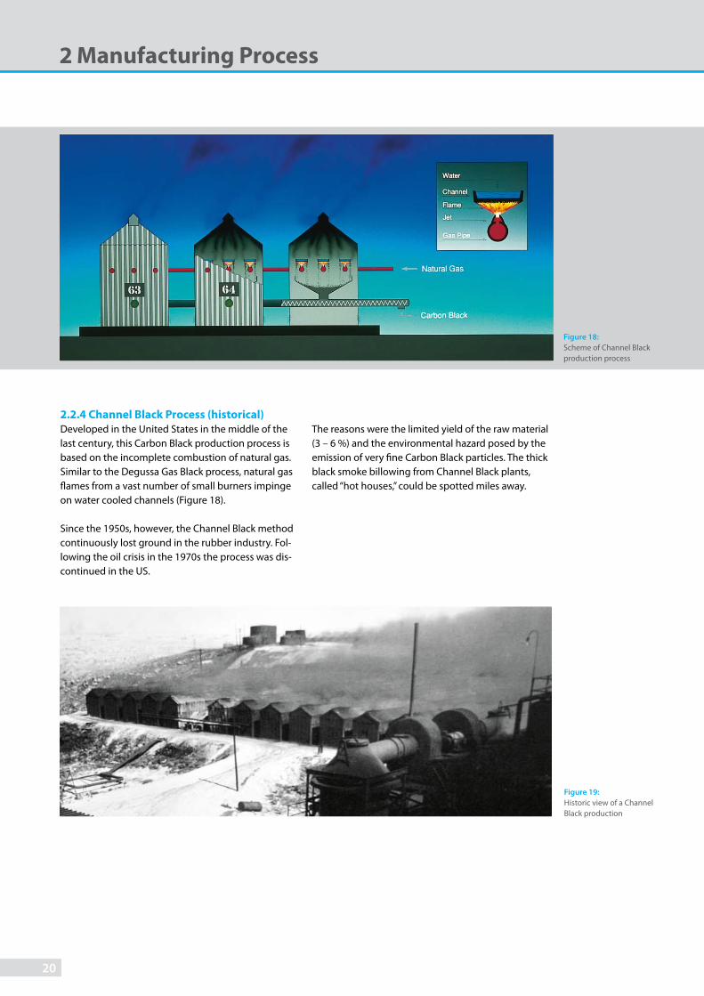
2.2.4 Channel Black Process (historical)
Developed in the United States in the middle of the last century, this Carbon Black production process is based on the incomplete combustion of natural gas. Similar to the Degussa Gas Black process, natural gas fl ames from a vast number of small burners impinge on water cooled channels (Figure 18).
Since the 1950s, however, the Channel Black method continuously lost ground in the rubber industry. Fol-lowing the oil crisis in the 1970s the process was dis-continued in the US.
Figure 18:
Scheme of Channel Black production process
The reasons were the limited yield of the raw material (3 – 6 %) and the environmental hazard posed by the emission of very fi ne Carbon Black particles. The thick black smoke billowing from Channel Black plants, called “hot houses,” could be spotted miles away.
Figure 19:
Historic view of a Channel Black production
20

2.3.1 Thermal Black Process
This method of producing Carbon Black is a non-continuous or cyclic process, with natural gas as the most commonly used feedstock, although higher grade hydrocarbon oils are also used. A Thermal Black plant delivers maximum effi ciency when operated in a tandem mode. It consists of two reactors operating alternately in cycles lasting fi ve to eight minutes. One of which is heated with a natural gas or oil/air mix-ture while the other is fed with pure feedstock which undergoes thermal decomposition (Figure 20).
One could also include the Thermal Black method in the group of thermal-oxidative processes, with the distinction that the energy generation and the decom-position reaction are not simultaneous. However, the fact that the actual Carbon Black formation occurs in the absence of oxygen and at decreasing temperature, results in Carbon Black properties that are markedly diff erent from those achieved by thermal-oxidative processes.
2.3 Thermal Decomposition Processes
Figure 21:
Electron microscopeview of Thermal Black particles
Figure 20:
Scheme of Thermal Black production process
Thermal Blacks form relatively slowly, resulting in coarse primary particle sizes ranging from 300 to 500 nm (Figure 21), referred to as medium thermal. However, formerly when using only natural gas as feedstock it was possible to dilute it with inert gases which would produce a Thermal Black composed of primary parti-cles in the range from 120 to 200 nm. This was referred to as fi ne thermal, the latter has virtually disappeared from the market.
21

2.3.2 Acetylene Black Process
At higher temperatures, exothermic decomposition of acetylene yields carbon and hydrogen, forming the basis of the Acetylene Black process. Hydrocarbons are usually added to acetylene in order to prevent reactor temperatures from rising due to the exothermic reac-tion. Once the reaction mixture has cooled down, the Carbon Black is separated from the hydrogen.
Figure 22:
Electron microscope view of Acetylene Black particles
2 Manufacturing Process
The way Acetylene Blacks are created markedly distinguishes them from thermal-oxidative Carbon Blacks. Although the median primary particle size of Acetylene Black is in the same range as that of some Furnace Blacks (30 to 40 nm), the structure diverges noticeably from the spherical form (Figure 22).
22

Carbon Blacks can also be delivered to the customer in the form of dispersions, which are used to address special dispersibility issues at the customer’s site and also keep pollution levels as low as possible during onward processing. Here a Carbon Black is dispersed in a variety of liquid and solid media in a wide range
Table 3:
Carbon Black compounds
2.4 Carbon Black Dispersions, Compounds, Plastic
and Rubber Masterbatches
Carbon Black Compounds Properties
Aqueous Dispersions Liquid to paste-like products
Pre-Dispersions Powdery products containing water, solvents, wetting agents or softeners
Pastes Paste-like products containing resins, softeners, wetting agents, etc.
Chips Solids, e. g. Carbon Black/nitrocellulose compounds
Plastic Masterbatches Granulated concentrates with up to 50 % Carbon Black content
Rubber Masterbatches Carbon black-filled rubber, also in powder form
Oil Pellets Oil-containing granules for printing inks
of concentrations. The type of Carbon Black and base media are usually specifi ed by the customer leading to a variety of products referred to as Carbon Black preparations. These compounds are classifi ed based on their external appearance (Table 3).
23

The obvious property of Carbon Black is the
deep black color, which is included in the
designation in many languages. Carbon
Black is classified as a solid and is initially
formed as an aerosol or free-floating par-
ticles. This is why just-formed Carbon Black
has a flaky appearance and is referred to as
fluffy Carbon Black at this stage.
3 Properties of Carbon Black
Particle Surface
O
O
O
O
O
OO
O
O
O
OH
O
OH
OH
OO
Carboxyl
Phenol
AnhydrideQuinone
Lactone
Ether
Peroxide
Hemiacetal
Ketone
acidic alkaline
As shown by chemical analysis, non-treated Carbon Black consists of almost pure carbon. Nevertheless, using the periodic table designator “C” to describe the product would be misleading and therefore not par-ticularly helpful.
To characterize Carbon Black, several physical and chemical properties have to be taken into account. Further insights are only possible after incorporating the various types of Carbon Black into the mediums chosen for its possible applications.
Figure 23:
The surface of Carbon Black can bind oxygen in the form of acidic or alkaline functional groups.
24

The composition described below refers to all Carbon Black grades, regardless of the production method used. Process-related variations have already been addressed in the description of the various methods in use today for obtaining Carbon Black. Without the use of photographic image analysis the primary particles of Carbon Black cannot be seen with the naked eye. It takes the tremendous magnifying power of a scan-ning electron microscope (SEM) to show that Carbon Black consists of chain-like clusters composed of spherical particles, the so-called primary particles. The product is not supplied in the form of isolated primary particles, but as larger, tightly bonded aggregates which form the primary building blocks. The primary particles vary in size and shape to impart specifi c application properties. The primary particle size is mentioned to indicate the application properties of a given product. The aggregates typically form micro-scale agglomerates during production, present in the supplied powders or pellets.
Figure 24 depicts an SEM view of a single particle. The formation of spherical, branched aggregates, where the primary particle can have diameters between 10 and 500 nm, is typical of products that develop from the gaseous phase. As we cannot see and measure primary particles without involving expensive equip-ment and time consuming methods this form of Car-bon Black has led to the defi nition of two properties
3.1 General Physical and Chemical Properties
Element Content (% of wt.)
Carbon 96 – 99.5
Hydrogen 0.2 – 1.3
Oxygen 0.2 – 0.5
Nitrogen 0 – 0.7
Sulfur 0.1 – 1.0
Residual Ash < 1
Table 4:
Typical elemental Carbon Black composition
Figure 24:
Scanning electron microscope view of a Carbon Black aggregate consisting of fused primary particles (magnification: x 120,000)
that are of primary signifi cance when it comes to char-acterizing Carbon Blacks and defi ning their suitability for specifi c applications:
• The specifi c surface area (m2/g) of Carbon Black is a function of primary particle size. Looking at geo-metric proportions, we can determine that smaller Carbon Black primary particles have a higher specifi c surface area.
• The structure designates the three-dimensional arrangement of primary particles in the aggregate. Extensive interlinking or branching characterizes a “high structure”, whereas less pronounced inter- linking or branching indicates a “low structure”.
Electron microscopy combined with X-ray structural micro-analysis, shows that these primary particles consist of concentrically arranged, graphite-like crys-tallites. By partially fusing together, the graphite layers are often twisted into each other, exhibiting a disor-dered state. A single primary particle can contain up to 1,500 of such crystallites.
25

3 Properties of Carbon Black
Figure 25:
Specific volume resistance curves for filled HD poly-ethylene samples relative to Carbon Black content
Carbon Black can thus be considered as a highly dis-ordered form of graphitic carbon. By heating the sub-stance to 3,000°C under inert conditions it develops into an ordered graphitic formation.
Turning back to chemical analysis, we see that, besides carbon the elementary analysis of normal Carbon Black also yields minute quantities of oxygen, hydro-gen, nitrogen and sulfur (Table 4). Most of these ele-ments are concentrated on the surface of the Carbon Black. The removal of traces of organic elements is possible with the use of special solvents. The Carbon Black extraction based on toluene mostly results in values less than 0.1 %.
Partially, the element of hydrogen is directly fused to the carbon element. However, together with oxygen, another portion forms surface-bound functional groups that can be identifi ed by analysis, both quali-tatively and quantitatively. Carbonyl, carboxyl, pyrone, phenol, quinone, lactol and ether groups have been identifi ed as the oxygen-containing groups that may be bound to the surface of the Carbon Black particle. Heating the substance up to 950°C, in the absence of oxygen, results in separation. This explains their des-ignation as “volatile matter”.
Oxygen containing functional groups on the Carbon Black surface can also be created through specifi c oxi-dative post-treatment. Oxygen content levels of 15 % and higher are possible. These Carbon Black types are especially suitable for treatment with polar binders.
Sulfur is present in a variety of forms: in its elementary form, as a bound molecule and in an oxidized state. High sulfur contents import a certain acidity to the Carbon Black.
Table 5:
Typical concentrations of trace metals
Nitrogen, when present, is usually contained in the graphite grid. Sulfur and nitrogen contents are contin-gent upon feedstock type and quality.
Carbon Black also contains traces of metals. The amounts and types depend on the feedstock used. Table 5 provides an overview of the metals and their relative content based on OEC`s Rubber and Specialty Carbon Blacks.
Metals Present in Carbon Black
Element Content in ppm
Antimony < 10
Arsenic < 10
Barium < 10
Cadmium < 1
Chrome < 5
Cobalt < 5
Copper < 5
Lead < 10
Nickel < 10
Mercury < 1
Selenium < 10
Zinc < 10
Among the physical properties of Carbon Black, the following two are important:
Density: According to literature and depending on the method used, it may vary from 1.7 to 1.9 g/cm3.
Electrical Conductivity: This aspect is usually not measured in the Carbon Black itself but in the com-pound containing the Carbon Black, i.e., a polymer or binding agent. Conductivity of a fi lled polymer in creases with the specifi c surface area and the struc-ture of the incorporated Carbon Black. It is also depen-dent on the Carbon Black concentration and disper-sion as well as on the type of polymer or binding agent used (Figure 25).
1018
1016
1014
1012
1010
108
106
104
102
100
501 01 52 0
Carbon Black Content [% by wt.]
PRINTEX® 45PRINTEX® LPRINTEX® XE 2
26

3.2 Definition of Carbon Black
Having described the various processes for obtaining Carbon Black and the resulting product properties, we can summarize the defi nition of Carbon Black as follows:
Carbon Blacks are chemically and physically
defi ned products obtained under controlled
conditions. Insofar as they are not treated
oxidatively, they consist of more than 96 %
pure carbon particles and minute quantities
of oxygen, hydrogen, nitrogen and sulfur.
The negligible amount of organic substances
on the surface of the Carbon Black particle
(mostly less than 0.1 %) can be extracted
using toluene. Metal concentrations are like-
wise negligible. Primary Carbon Black parti-
cles, ranging from 10 to approx. 500 nm, fuse
into chain like aggregates. This defi nes the
structure of individual Carbon Blacks.
Carbon Blacks that are treated oxidatively
diff er from those that are not, in the sense
that they may contain up to, and sometimes
exceeding, 15 % oxygen.
On the other hand, soot (chimney soot and diesel exhaust soot) is a by-product of the uncontrolled combustion of hydrocarbons. Obtaining precise data on the composition of soot is virtually impossible because the conditions under which it is created are fl uctuating, precluding any consistency in terms of
quality and properties. Soot can be diff erentiated from Carbon Black based on inorganic and organic impu-rity contents. Chimney soot, for instance, may have a carbon content of less than 50 %, an extract content of more than 15 % and an ash content of more than 20 %.
27

3 Properties of Carbon Black
For a long time, characterizing Carbon Blacks was a question of determining diff erent shades of black with the human eye. Precise data on reinforcing eff ects was available only to a limited degree. What exactly the characteristics of a particular Carbon Black were and what it could be used for were questions that could not easily be answered. In many cases, the develop-ment of new Carbon Black grades happened before the characterization of their properties, very much a “hit-and-miss”-situation.
Following the introduction of the Furnace Black meth-od, initially there were only a few basic grades listed. In the mid-1960s it was discovered that the addition of alkaline metal salts during the production process could be used to infl uence the Carbon Black structure. This was the fi rst major advancement which led to a broader typology of Furnace Blacks.
For the application to tire treads, high-structure Carbon Blacks were introduced in the rubber industry in the 1960s to improve abrasion resistance. To determine their structure a quick test method had to be developed.
3.3 Test Methods, Chemical and Physical Data
1950
Furnace Black History
1960 1970 2000
2nd stage
3rd stage
4th stage
1st stage
Iodine number specific surface area
Furn
ace
Bla
ck P
erf
orm
an
ce
DBP absorption-“structure”
“New technology Blacks”
“ECORAX® Blacks”
Figure 26a:
Furnace Black history
Following a series of comparative tests, DBP (dibutyl phthalate) absorption ultimately became the pre-ferred tool for determining Carbon Black structure.
Diffi culties arose in the early 1970s when advances in technology led to a new category of reinforcing Carbon Blacks in Furnace Black production. Compared to the standard grades available at the time these so-called new technology or improved blacks showed improved abrasion resistance without any apparent change in the iodine number. The diff erences between these new technology blacks and standard Carbon Blacks were not easily detectable with the methods available at the time. Therefore, physical and chemi-cal characterization methods had to be developed in order to establish production parameters, which ensured that the correct Carbon Black characteristics were achieved. One of these new methods focused on the determination of the Carbon Black surface area (CTAB adsorption cf. p. 32).
28

Further development and refi nement of Orion’s CarbonBlacks for the rubber industry has led to specifi cally surface structured blacks (ECORAX® grades), which were fi rst introduced at the beginning of the millen-nium. These Carbon Blacks feature a rougher micro-surface in the nanometer range and deliver improved dynamic properties in vulcanized rubber compounds versus comparable ASTM Carbon Blacks.
The development of PUREX® Carbon Blacks was another step towards more sophisticated and product orientated Carbon Blacks. These Carbon Blacks address the needs of the rubber industry for clean and easily dispersible soft blacks, especially those used in the production of mechanical rubber goods for the auto-motive industry.
With hindsight, we can say that the development of the electron microscope in the 1940s proved a major milestone in terms of analyzing Carbon Black and specifying diff erent grades for diff erent applications. Where empirical methods used to be the only option for characterizing Carbon Blacks, this new technology made it possible to conduct scientifi c analyses based on particle diameter, particle aggregation and even particle classifi cation in terms of shape and surface details. The research showed that virtually no two Carbon Black particles are exactly alike.
Figure 26b:
Scanning tunneling microscopy (STM)
Higher surface roughness for ECORAX® black due to smaller crystal-lites and more disordered arrangement of crystallites
Conventional Furnace Blacks
29

3 Properties of Carbon Black
All Carbon Black characterization methods existing today are used to defi ne collective properties, which are based on the sum of properties determined for the individual particles. This means that we are dealing with a maximum variation of particle properties in a range with statistical maximum. It is up to the skilled technician to adjust the peak of the distribution curve at a specifi c value and defi ne the width of the curve. As long as geometric data is what is being processed and analyzed, the electron microscope is a helpful tool in determining the distribution curve. Other param-eters, like conductivity, cannot be determined for the individual particles.
As already pointed out, the average primary particle size and the average aggregate size form the primary characteristic data. However, the particle size distribu-tion and the aggregate size distribution are at least as important. As an alternative to lengthy electron microscope analysis a number of methods have been developed to enable a quicker characterization and allow conclusions to be drawn for subsequent Carbon Black applications. While various surface characterization methods have gradually replaced those for particle size determination, the aggregate size distribution is now determined via specialized methods such as sedi-mentation, ultra-centrifugation and light refraction.
De facto there are various characterization methods in use today, which indicate that a general characteriza-tion of Carbon Black is impossible. It is necessary to specifi cally adapt identifying methodologies to the various areas of application.
Most Carbon Black properties are determined based on industry standards, which have been developed by the German Institute of Standardization (Deutsches Institut für Normung e.V. - DIN), the International Organization for Standardization (ISO) and the ASTM International (formerly known as the American Society for Testing and Materials). These standards are not only used as a measure by which Carbon Blacks are characterized, but also as a quality assurance tool for the production process (Table 6).
In addition to these Carbon Black reference profi les, a number of more practical testing methods are used today, especially for testing Rubber Carbon Blacks in relation to their end use segments. These tests may be conducted in standard rubber formulations and are used to establish characteristic and consistent profi le data on the impact of the Carbon Black in the rubber compound.
Obviously, these methods off er only a glimpse of the comprehensive systems available for testing and eval-uating Rubber Carbon Blacks. Special testing methods also exist for Carbon Black applications in the plastics, coatings and printing inks industries. However, we will not expand on them any further here.
In the following chapters the main measurement methods are described in more detail.
1) Determination of toluene extract
Figure 27:
Test methods
2) Measurement of nitrogen surface area/STSA
30

Table 6:
Carbon Black test methods. *) DIN EN ISO method**) DIN ISO method
3) Measurement of oil absorption capability (OAN)
Standardized Carbon Black Test Methods
Description ISO ASTM DIN
Surface Area
Iodine Adsorption Nitrogen Surface Area/STSA
1304 4652/18852
D 1510 D 6556
66132
Structure/Rheology
OAN COAN Oil Absorption
4656 4656 787/5
D 2414 D 3493
*)
Colorimetry
JetnessTint Strength 5435 D 3265
55979
Chemical Analyses
Volatile Components Ash Residue Moisture Sieve ResidueNon-Dispersible MatterToluene Extract Transmittance of Toluene Extract pH
1125 787/2 787/18
6209 3858 787/9
D 1506 D 1509 D 1514D 7724D 4527 D 1618 D 1512
53552 53586 *) *)
*)
External Appearance/Texture and Handling
Properties
Pour Density Individual Pellet Hardness Pellet Size Distribution
1306
8511
D 1513 D 3313/D 5230 D 1511
**)
4) Measurement of iodine adsorption
Figure 27:
Test methods
31

3 Properties of Carbon Black
3.3.1 Determination of Surface Area
The specifi c surface area of a Carbon Black is mainly derived from the particle geometry using adsorption methods. Iodine adsorption, measured in mg/g, is the most common technique.
Iodine adsorption is a quick test method for dry Car-bon Black. Surface groups and adsorbed substances infl uence this specifi cation method. For the iodine number to refl ect the real surface area, it is important that neither increased amounts of volatile matter nor higher toluene extracts disturb the measurement. This in turn limits this method to Furnace Blacks with low toluene extractions and Lamp Blacks. Furnace Blacks with high contents of solvent extractable material, Gas Blacks and treated Carbon Blacks cannot be analyzed using this method. That is mainly why this parameter is usually not stated when dealing with Specialty Car-bon Blacks.
CTAB adsorption, introduced primarily for the char-acterization of improved Carbon Blacks, comes closest to an accurate determination of the geometric surface, i.e., not including the pores. That is because cetyl trimethyl ammonium bromide (CTAB) has a greater space requirement than nitrogen. This is also why the CTAB number correlates well with particle size, allow-ing for meaningful predictions on Carbon Black prop-erties and behavior in the application environment.
More modern methods to measure the surface area are the BET multipoint nitrogen absorption and the associated STSA (Statistical Thickness Surface Area). It has always been recognized that the multipoint nitrogen surface area was the most accurate way of measuring the total surface area of the primary par-ticle. However, limitations in equipment, did not allow this to become a standard. With the introduction of new automated test equipment it became possible to receive the results of the BET multipoint and the STSA with minimum eff orts and in a much shorter testing time. It is generally accepted that a combina-tion of these two measurements more clearly defi nes the surface area of a Carbon Black. This allows better process control and gives values, which relate to the Carbon Black´s performance potential. Today STSA has basically replaced CTAB surface area.
Conversely, the particle size itself can be used to deter-mine the geometric surface. This value is obtained from electron microscope photographs, which make it possible to measure the particle size, determine the distribution curves and calculate the surface area values. Although it is a very important tool in the Car-bon Black industry, the method is too time-consuming and complex and the equipment is too expensive for obtaining profi le data for everyday use.
32

Figure 28:
Primary particle size and jetness
3.3.2 Determination of Structure
The structure of Carbon Black aggregates can only be determined indirectly.
The most commonly accepted method is based on oil absorption. In this test, paraffi n oil (formerly dibutyl phthalate, DBP) is added by means of a constant-rate burette to a sample of the Carbon Black in the mixer chamber of an absorptometer. As the sample absorbs the oil the mixture changes from a free-fl owing pow-der to a semi-plastic continuous mass. This leads to a sharp increase in viscosity, which is transmitted to the torque-sensing system of the absorptometer. The end-point of the test is given by a pre-defi ned torque level. The result is expressed as the oil absorption number (OAN), in ml/100 g. A high OAN number corresponds to a high structure, i.e. a high degree of branching and clustering of the aggregates.
Mechanical stress can be applied to destroy agglomer-ates. This eff ect is used for determining the structure based on the oil absorption of a compressed sample (COAN). Following four repeated applications of pres-sure at predefi ned levels, the oil absorption of the mechanically stressed Carbon Black is measured by the conventional oil absorption method. As a general rule, COAN values are lower than OAN values.
Another parameter, Carbon Black oil absorption according to ISO 787/5, is measured using the so-called fl owpoint method. The fl owpoint registers the maximum quantity of oil (usually linseed oil) that can be added to Carbon Black and still allow for a non-deli-quescent cone to form from the mixture. Although the method is not the most accurate, oil absorption is an important indicator in coating applications because a high oil absorption level points to a high binding agent requirement. The Carbon Black structure and particle size, but most of all density and surface chem-istry, all have an eff ect on oil absorption.
3.3.3 Colorimetric Characterization
Jetness refers to the intensity of blackness that is achievable. The most accurate instrument for mea-suring what are often very minute diff erences is the trained eye which can diff erentiate between up to 100 diff erent shades of black. A method for measuring residual refl ection (<0.5 %), invented by OEC, became a standard known as DIN Norm 55979. A Carbon Black sample mixed with linseed oil and measured with a spectral photometer results in an MY value. The fi ner the Carbon Black particle is, the higher the MY value would be (Figure 28).
A refi ned version of the paste method described above consists of determining the MY factor in an alkyde/melamine resin lacquer. The jetness achieved is mapped against various group standards and is indicated as a relative blackness value fi gure MYr for optimum reproducibility and consistency.
Tint strength refers to a colorimetric parameter: it is the coloring ability of a Carbon Black as measured against a white pigment (zinc oxide). However, tint strength is infl uenced by the particle size and struc-ture but also, to some extent, by the particle size distribution. The fi ner the Carbon Black particles are, the greater the tint strength is, an indirect indicator of surface or particle size specifi cation. On the other hand, a lower structure causes greater tint strength. Thus, tint strength by itself can often lead to a serious misinterpretation of the reinforcing capability of a Carbon Black and should therefore always be viewed in relation to both structure and surface area.
The tint strength as well as the relative Grey Value GYr (based on a polymer-coating system) will be given as a percentage relative to a standard of Specialty Carbon Black.
290
280
270
260
250
2401510 20 25
Primary particle size [nm]
Blackness value MY
Gas Black treatedGas Black
33

3 Properties of Carbon Black
Figure 29:
Control room of a Carbon Black plant
3.3.4 Chemical and Physical Measurements
The volatile matter content gives an indication of the Carbon Black’s oxygen concentration and is deter-mined by heating the Carbon Black up to 950°C. This parameter is especially important for testing Carbon Blacks that have been post-treated.
The ash content points to the level of inorganic impurities coming primarily from the feedstock - iron, calcium and silicon are among the most common. Gas and Acetylene Blacks are characterized by a very low ash content due to their production process.
The sieve residue provides information on particulate impurities which may contain metal or ceramic particles originating from the production unit or coke particles formed during the production process.
As a result of their high adsorbency, moisture is an issue when storing Carbon Black. High-structure Car-bon Blacks, and in particular oxidatively post-treated Carbon Blacks, are more likely to have elevated mois-ture content levels.
The pH of a Carbon Black is measured in an aqueous suspension. Untreated Carbon Blacks have a diff erent pH depending on the process used: Gas Blacks are always acidic because of their oxidized surface. Fur-nace Blacks, on the other hand, are generally alkaline because small quantities of basic oxides are present on the surface. Lamp Blacks, Thermal Blacks and in some cases also Acetylene Blacks are characterized by alkaline to neutral reactions.
3.3.5 Physical Appearance and Handling
Properties
To determine the space requirement of powder and pelletized Carbon Blacks either the bulk or pour den-
sity, or the compacted or tapped density, is measured. The structure is refl ected by pour density. High-struc-ture Carbon Blacks show a lower bulk density than low-structure Carbon Blacks.
In the case of pelletized Carbon Blacks, the pellet
hardness is a signifi cant quality parameter as it gives an indication of pellet fragility and hence of the resis-tance to attrition rate. This resistance is characterized by pellets being destroyed and ultimately ground to dust by friction. While softer pellets make for better dispersion, their inherent propensity towards fi nesse may create handling issues. The pellet size distribu-
tion is a parameter that aff ects the fl ow characteristics of pelletized Carbon Blacks. A uniform pellet size means a lower bulk density, hence ensuring optimum fl ow behavior.
34

Some of the parameters described above are part of the Carbon Black specifi cations decided on jointly between the customer and the manufacturer. Although these mainly concern surface and structure specifi cations, they may also address specifi c require-ments as they relate to the Carbon Black application.
Key parameters are checked at regular intervals during the production process as part of production control activities.
One aspect which is important to both manufacturers and users of Carbon Black is the continued consistency in type and quality. This is a direct function of the production process and process control (Figure 29). Quality assurance, in terms of product uniformity and reproducibility, is as important as meeting the cus-tomer’s individual specifi cations.
3.4 Specifications and Quality Assurance
Figure 30:
Process control chart
Most manufacturers therefore incorporate statistical process control (SPC) in the Carbon Black production process. SPC is a system that builds on universally accepted specifi cations and guidelines for quality assurance.
The most important target values for individual rubber blacks, to ensure optimum production processes, were laid down by ASTM International (ASTM D 1765), e.g., parameters for iodine adsorption and OAN absorption (Figure 30).
These parameters are determined at regular intervals throughout the production process. They not only ensure a smooth production process, but also help achieve optimum consistency in terms of end product quality. The “Capability lndices”, Cp and Cpk, give an indication of parameter variances and their deviation from target values.
105
102
99
96
93
Time
OA
N [
ml/
10
0g
]
35
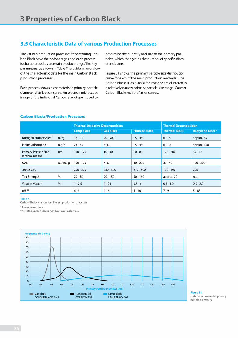
Figure 31:
Distribution curves for primary particle diameters
3.5 Characteristic Data of various Production Processes
The various production processes for obtaining Car-bon Black have their advantages and each process is characterized by a certain product range. The key parameters, as shown in Table 7, provide an overview of the characteristic data for the main Carbon Black production processes.
Each process shows a characteristic primary particle diameter distribution curve. An electron microscope image of the individual Carbon Black type is used to
determine the quantity and size of the primary par-ticles, which then yields the number of specifi c diam-eter clusters.
Figure 31 shows the primary particle size distribution curve for each of the main production methods. Fine Carbon Blacks (Gas Blacks) for instance are clustered in a relatively narrow primary particle size range. Coarser Carbon Blacks exhibit fl atter curves.
Carbon Blacks/Production Processes
Thermal-Oxidative Decomposition Thermal Decomposition
Lamp Black Gas Black Furnace Black Thermal Black Acetylene Black*
Nitrogen Surface Area m2/g 16 – 24 90 – 500 15 – 450 6 – 15 approx. 65
Iodine Adsorption mg/g 23 – 33 n. a. 15 – 450 6 – 10 approx. 100
Primary Particle Size (arithm. mean)
nm 110 – 120 10 – 30 10 – 80 120 – 500 32 – 42
OAN ml/100 g 100 – 120 n. a. 40 – 200 37 – 43 150 – 200
Jetness MY 200 – 220 230 – 300 210 – 300 170 – 190 225
Tint Strength % 20 – 35 90 – 150 50 – 160 approx. 20 n. a.
Volatile Matter % 1 – 2.5 4 – 24 0.5 – 6 0.5 – 1.0 0.5 – 2,0
pH ** 6 – 9 4 – 6 6 – 10 7 – 9 5 – 8*
Table 7:
Carbon Black variances for different production processes
* Pressureless process** Treated Carbon Blacks may have a pH as low as 2
3 Properties of Carbon Black
80
90
70
60
50
40
30
20
10
01002 03 04 05 06 07 08 09 0 100 110 120 130 140
Frequency (% by wt.)
Primary Particle Diameter (nm)
Lamp Black LAMP BLACK 101
Furnace Black CORAX® N 339
Gas BlackCOLOUR BLACK FW 1
36

37

Significant advances have been made in the area
of handling and shipping granulated and powdery
goods in recent years. New systems for perfectly
sealed storage and transportation in particular have
greatly benefitted the Carbon Black industry. Carbon
Blacks are marketed in the form of powder Carbon
Black (Specialty Carbon Blacks) and pelletized Car-
bon Black (Specialty Carbon Blacks and Rubber Car-
bon Blacks). The handling systems differ substantially
depending on the type of Carbon Black for which
they are designed.
4 Handling
Figure 32:
Carbon Black packaging
1) FIBC 2) Paper bags
Depending on their type, powder Carbon Blacks can more or less easily be fl uidized pneumatically. This makes it possible to convey them in large quantities over relatively long distances using high air volumes. Screw conveyors are used mainly for shorter distances.
Due to their low bulk density and relatively poor fl ow characteristics, powder Carbon Blacks are not usually shipped in rigid vessels or silos, but rather packaged in bags or FIBCs (Flexible Intermediate Bulk Container) as shown in Figure 32.
38

Pelletized Carbon Blacks, on the other hand, are much easier to handle. Despite their signifi cantly bet-ter fl ow and conveying properties, the pellet forms require special precautions to prevent the pellets from being crushed during transport. Otherwise, fl ow char-acteristics and onward handling may be signifi cantly degraded, which could possibly lead to production downtime and equipment failure due to clogging. That is why conveyor belts and bucket elevators are still commonly used for intra-plant Carbon Black trans-fers. When pneumatic systems are used it is important to employ low velocity conveying systems (Figure 33).
One aspect to keep in mind is that wet-pelletized Car-bon Black is usually characterized by a greater pellet hardness than dry-pelletized or oil-pelletized Carbon Black. The appropriate conveying system must be chosen depending on the pellet hardness, considering the strength of the pellets against the applied forces.
Dense-phase conveying systems off er the gentlest conveying of such materials while dilute-phase conveying and even dune-phase conveying are not recommended because the resulting damage to the pellets during transportation is too high. Short dis-tances are best bridged using screw conveyors, fl uid channels or vibratory feeders.
The transportation of Carbon Black in 25 kg bags is by far the least common. About 85 % of the global Carbon Black is delivered in bulk (road and rail cars) and semi-bulk containers such as FIBCs or customer owned IBCs (Intermediate Bulk Containers, so-called bins).
Figure 33:
Carbon Black handling and shipping
1) Pneumatic conveyor system for Carbon Blacks 2) Truck containers
39
5 Product Safety
5.1 Toxicology
Human Experience
In decades of Carbon Black production and processing using a variety of methods, no signifi cant hazardous eff ects have been registered.
Acute Toxicity
Carbon Black has an acute (oral) toxicity LD50 of > 8000 mg/kg bw. Carbon Black applied on the intact skin and to the eye of the rabbit does not cause irritat-ing or corrosive eff ects. Carbon Black did not induce skin sensitisation eff ects in guinea pigs (OECD guide-line 406). In humans, no cases of skin or respiratory allergies have been reported.
Repeated Dose Toxicity
Carbon Black has a NOAEL of 1 mg/m3 (respirable) after repeated inhalation of rats for 13 weeks. Based on human data, a NOAEL can be estimated at 2 mg/m3 (inhalable).
Chronic Toxicity
In the early 1990s, extended long-term inhalation studies with rats showed lung fi brosis and tumor development in the case where the lungs were over-loaded with Carbon Black particles. Mice and hamsters did not develop lung tumors under similar testing conditions. Although the signifi cance of eff ects seen in rats under overload conditions for human risk assess-ment is today still controversially discussed.
In October 1995, the International Agency for Research on Cancer (IARC) had evaluated available data on Carbon Black and amended its initial overall rating of Carbon Black from Category 3 to Category 2B (“possible human carcinogen”) based on two long-term inhalation studies performed in rats under condi-tions of lung overload. Based on human (epidemiolog-ical) data, IARC concluded that there was “inadequate evidence” linking exposure to Carbon Black to cancer development in humans. In subsequent evaluations of Carbon Black in 2006 and 2010, IARC upheld its previ-ous rating. As a consequence of the IARC evaluation, Carbon Black is now included in the Danish cancer list and classifi ed as a D2 A substance (poisonous and infectious material) and in the Canadian Workplace Hazardous Materials Identifi cation System (WHMIS) under the Canadian Environmental Protection Act (CEPA). The German MAK Commission reviewed Carbon Black in 1998. The overall rating of this commission is Category 3B (“possible human carcinogen”) also based on the long-term inhalation studies on rats under conditions of lung overload.
Based on fi ndings by the National Toxicology Program (NTP/USA) as well as the European (excluding Den-mark) and American legislation regarding chemicals (OSHA), Rubber Carbon Blacks and Specialty Carbon Blacks do not exhibit Carbon a mutagenic, teratogenic or carcinogenic risk.
40

5.2 Safety-Related Properties
Under normal application conditions Carbon Black does not pose a potential explosive hazard. How-ever, in the presence of signifi cant igniting energy, e.g., a welding torch, Carbon Black/air mixtures may explode. For this reason, Carbon Black sources must be removed or hermetically sealed prior to equipment repairs in the vicinity of welding processes or equip-ment generating high operating temperatures.
Carbon monoxide build-up is possible in sealed con-tainers such as silos or in unventilated storage facilities. Due to the toxic and extremely fl ammable properties of carbon monoxide, ignition sources should be removed and self-contained air supply systems should be used.
Carbon Black should be stored under dry conditions. During activities where the workplace limit value valid for Carbon Black are exceeded, an air suction system should be in operation or work personnel be required to wear protective dust masks. For most countries the general dust exposure limit applies for Carbon Black. The country-specifi c OEL for Carbon Black can be obtained from our safety data sheets which are obtainable from our website. To prevent Carbon Black emissions and dust build-up, implementation of good engineering and housekeeping practices as well as eff ective dust removal systems are recommended.
Further details regarding safe handling of Carbon Blacks are described in the relevant safety data sheet (SDS).
Ecotoxicology
Carbon Black is an inorganic water insoluble sub-stance. For this reason its bioavailability for aquatic organisms is very low. In acute tests according to OECD test guidelines with fi sh, daphnia and algae, nominal concentrations of 1.00 mg/l showed no eff ects. Based on the physicochemical and acute toxicological data, no chronic eff ects and no bioaccu-mulation are to be expected in aquatic organisms. The
general guidelines for the examination of the biode-gradability of substances (OECD, EEC-guidelines) can be used only for organic substances. Carbon Black is an inert inorganic substance with the structural for-mula “C” and is not biodegradable by microorganisms. The German commission for the evaluation of water polluting substances has classifi ed Carbon Black as a “not water endangering” substance (KBwS-No: 1742).
Special Requirements
Many Carbon Blacks fulfi ll the governmental stan-dards for additives that are used in articles that come into contact with food, drinking water and toys. For more detailed information, please contact the Product Stewardship and Health Department:
Orion Engineered Carbons GmbHHahnstraße 4960528 Frankfurt am MainGermany
phone +49 69 36 50 54 - 165fax +49 69 36 50 54 - [email protected]
41

Once you consider its possible uses you will find that
there are many answers to the question
“What is Carbon Black?”.
Indeed, the physical and chemical properties dis-
cussed so far hint at a broad spectrum of applications.
The high degree of light absorption, for instance, is
one aspect that makes Carbon Black so useful in the
coatings, plastics and printing industries.
6 Applications
6.1 Rubber Carbon Blacks
The primary particle size, the aggregate formation and the surface activity have all led to the important appli-cation of Carbon Black as a reinforcing agent in rubber applications. These Carbon Blacks are most commonly referred to as Rubber Carbon Blacks.
The reinforcing eff ect of Carbon Black was discovered by accident rather than intentionally shortly after the turn of the 19th century. Until then zinc oxide was the substance of choice for eliminating the inherent sticki-ness of rubber. The discovery of the reinforcing prop-erties of Carbon Black represented a new dawn for the Carbon Black, tire and automotive industries. Now tires with improved textile cord could be produced to last longer if Carbon Black is used as a fi ller in the rub-ber compound instead of zinc oxide.
However, it took until the early 1920s before Carbon Black was generally used to reinforce tire rubber and other rubber products. Soon it also became clear that
there were signifi cant diff erences between the various types of Carbon Black, and that these distinctions evolved from processing characteristics and their eff ect on rubber properties. As a result, new typologies, such as MPC = Medium Processing Channel Black or HAF = High Abrasion Furnace Black, were established.
The demand for reduced rolling resistance and sub-sequently the labeling of tires steered the industry toward a solution for the truck and passenger car sector. The idea to use a suitable fi ller to achieve a lower rolling resistance inspired OEC to develop a new generation of Rubber Carbon Blacks under the brand name ECORAX®.
In the area of technical rubber components, the main criteria for modern Carbon Blacks are excellent dispersibility, processing reliability and quality consis-tency. The PUREX® family of Carbon Blacks developed by OEC for the MRG industry addresses these needs.
42

The following widely acknowledged typology of Car-bon Blacks based on reinforcing properties has stood the test of time:
Hard Blacks:
High reinforcing capability, fi ne Carbon Blacks, tire tread blacks (primary particle size: 1 – 30 nm)
Soft Blacks:
Semi-reinforcing capability, carcass Carbon Blacks (primary particle size: 31 – 200 nm)
Thermal Blacks:
Minor reinforcing capability, high fi lling rates (primary particle size: >200 nm)
Today a classifi cation according to ASTM D 1765 is widely used.
The fi rst character in the nomenclature system for Rubber Carbon Blacks indicates the eff ect of the CarbonBlack on the cure rate of a typical rubber compound containing the Carbon Black. The letter “N” is used to indicate a normal curing rate of typical Furnace Blacks that have received no special modifi cation to alter their infl uence on the curing rate of rubber. The letter “S” is used for Channel Blacks or for Furnace Blacks that have been usually modifi ed by oxydative methods, to
eff ectively reduce the curing rate of rubber. Channel Blacks characteristically impart a slower curing rate to rubber compounds. Thus, the letter “S” designates a slow cure rate. Carbon Blacks may vary considerably in curing rate within each of the two letter classifi cations.
A 3-digit number follows the fi rst character in the nomenclature system. The fi rst digit designates the average surface area of the Carbon Black as measured by nitrogen surface area. The surface area range of Carbon Black has been divided into 6 arbitrary groups. Each has been assigned a digit to describe that group (Table 8). The digits 2 and 3 have no connotative meaning.
The N300 series is characterized by a wide variety of Rubber Carbon Blacks, covering no fewer than 10 diff erent types. As mentioned above, fi ne-particle Carbon Blacks are used for rubber com-ponents that need to withstand signifi cant levels of mechanical stress, e.g. tire treads.
Soft blacks, on the other hand, are used in the tire car cass but also in technical rubber components, from windscreen seals to door seals and fl oor mats. More than 90 % of the world’s Carbon Black output is used in the rubber industry, hence the dominant role of Rubber Carbon Blacks.
Table 8:
ASTM Rubber Carbon Black typology (excerpt)
Rubber Carbon Blacks
Designation Nitrogen Surface Area (m2/g)
N100 121 – 150
N200 100 – 120
N300 70 – 99
N500 40 – 49
N600 33 – 39
N700 21 – 32
N900 < 10
43

6 Applications
In the coatings sector, treated, fi ne particle Carbon Blacks are the key to deep jet black paints. On the other hand, coarse Carbon Blacks, the so-called tinting blacks, are indispensable for obtaining a desired grey shade or color hue.
Carbon Black applications abound in the plastics in dustry. As in the coatings industry, fi ne-particle types are used for obtaining a deep jet black color. Its ability to absorb detrimental UV light and con-vert it into heat, makes plastics such as polyolefi nes, and especially polyethylene, more resistant to UV radiation. Anti-static treatment is also an important application area, as the related fi eld of compounds for power cables. The plastics sector also covers the black pigmentation of synthetic fi bers.
The paper industry uses Carbon Blacks with medium-sized particles mainly for decorative and photo-pro-tective products. Relatively coarse particles charac-terize the Carbon Blacks utilized in the construction industry.
Other special application areas, though not focused on the pigmentation properties of these Carbon Blacks, are also included here e.g., the production of carbon brushes and electrodes, as well as metal, metal oxide reduction and molten metal covering systems. All of these are most suitable for Lamp Blacks.
Though the list of applications is far from being exhausted, the uses described here give a good idea of the impact of Carbon Black in the world around us.
Carbon Black is one of the basic substances that is indispensable to industry and technology. It comes in many varieties, each tailored to applications in the most diverse areas. Indeed, Carbon Black has come a long way and who would have thought that Carbon Black would have such a bright future?
6.2 Specialty Carbon Blacks
Specialty Carbon Blacks have a number of advantages compared to black organic dyes:
• Color stability • Solvent resistance • Acid and alkaline resistance • Thermal stability • High hiding power
These Carbon Blacks are used for a variety of applica-tions in the printing, paints, coatings, plastics, fi ber, paper and construction industries. Here also the industry works with a widely accepted typology based on particle size. Although not considered an inter-national standard, it serves as the main reference for most manufacturers.
The classifi cation system identifi es four groups: High Color (HC), Medium Color (MC), Regular Color (RC) and Low Color (LC). The third letter refers to the manufacturing process: (F) for Furnace Black and (G) for Channel or Gas Black. Treatment is indicated by the suffi x (o).
New Specialty Carbon Blacks developed on an ongo-ing basis, are sustaining and driving the pace of inno-vation in the area of non-impact printing methods. Today, the Specialty Carbon Black manufactured according to the Degussa Gas Black method is at the forefront of the industry.
Table 9:
Specialty Carbon Black classification
Specialty Carbon Blacks
Designation Range of Median
Primary Particle Size*
(nm)Gas Blacks Furnace Blacks
HCG HCF 10 – 15
MCG MCF 16 – 24
RCG RCF 25 – 35
LCF > 36
Gas Blacks (treated)
HCG (o) 10 – 17
MCG (o) 18 – 24
RCG (o) > 25
44

Without Carbon Black ...
... the tires on your car would not provide that extra measure of durability and safety.
... your morning newspaper would never make it to the breakfast table on time.
... photocopiers might still be mimeograph machines.
... books would simply fade away.
... fashion would miss out on the elegance of a touch of black.
... grand pianos would only come in lighter shades.
... stretch limos would all be white.
... your car would miss the sealings which protect you from getting wet inside.
... there would be no anti-vibration measures and car rides could be quite bumpy.
45

6 Applications
46


OEC-06/2015
F o c u s e d. I n n o v a t i v e. R e s p o n s i v e.
All information and statements contained herein are believed to be accurate, however Orion Engineered Carbons GmbH (as well as all other Orion Engineered Carbons group companies including Orion Engineered Carbons SA), its agents and/or affi liates give no warranty with respect thereto, including but not limited to any results to be obtained or the non-infringement of any proprietary right. Use or application of such information or statements or the material or systems described herein is at user’s sole discretion and risk, and consequently user acknowledges that Orion Engineered Carbons GmbH (as well as all other Orion Engineered Carbons group companies including Orion Engineered Carbons SA), its agents and/or affi liates shall bear no responsibility or liability for same.Nothing herein shall be construed as a license of or recommendation for use, especially with concern to the potential infringement of any proprietary right. All sales are subject to the respective Standard Terms & Conditions of Sale issued by Orion Engineered Carbons GmbH or - as the case may be - another Orion Engineered Carbons group company, including but not limited to the Limited Warranty clauses contained therein.
© 2015 Orion Engineered Carbons GmbH
Global Corporate Headquarters
Orion Engineered Carbons S.A., 6 Route de Trèves, L-2633 Senningerberg, Luxembourg, Phone +352 27 04 80 60
The Americas
Orion Engineered Carbons LLC4501 Magnolia Cove Drive, Suite 106Kingwood, TX 77345USAPhone +1 832 445 3300
Europe/ Middle East/ Africa
Orion Engineered Carbons GmbHHahnstraße 4960528 Frankfurt am MainGermanyPhone +49 69 36 50 54 100
Asia Pacif ic
Orion Engineered Carbons Trading (Shanghai) Co., Ltd.BM Intercontinental Business Centre, Room 3701-3702100 Yutong Road200070 Shanghai, ChinaPhone +86 21 6107 0895
www.orioncarbons.com


