What Is New in Autodesk® Simulation CFD 2013? Ryan Arnaudin – Autodesk SM3215 Join us for an introduction to the new features and tools in Autodesk Simulation CFD 2013 software (formerly CFdesign®). In this class, we will provide an overview of improvements in the areas of ease of use, product interoperability, and performance. You will get an introduction to the new 2013 ribbon interface and options for customizing the user interface to suit your needs, and you will learn how repetitive tasks can be automated more easily. We will demonstrate improved CAD connections and simulation prep commands and show you how to use new tools to generate high-resolution renderings of your simulation results. Finally, we will review the new physics models and highlight improvements in both meshing and solver performance. Learning Objectives At the end of this class, you will be able to: Use and customize the new ribbon interface to set up CFD simulations with efficiency Describe new tools and features that assist with the automation of repetitive tasks Identify new physics models and areas of improvement in the mesher and solver Identify new and improved product interoperability workflows from CAD to CFD and from CFD to rendering About the Speaker Ryan is a User Experience Designer for Autodesk Simulation with an expertise in CFD. He holds a B.S. in Aerospace Engineering from Virginia Tech and, prior to his current position with Autodesk, acted in roles ranging from technical support to QA to product design at Blue Ridge Numerics, makers of CFdesign, which was acquired by Autodesk in March of 2011. Ryan is driven to understand simulation users and design tools that enable them to be more confident, efficient, and informed in the design process. Email: [email protected]Twitter: @arnaudin
Transcript
What Is New in Autodesk® Simulation CFD 2013? Ryan Arnaudin – Autodesk
SM3215
Join us for an introduction to the new features and tools in Autodesk Simulation CFD 2013 software (formerly CFdesign®). In this class, we will provide an overview of improvements in the areas of ease of use, product interoperability, and performance. You will get an introduction to the new 2013 ribbon interface and options for customizing the user interface to suit your needs, and you will learn how repetitive tasks can be automated more easily. We will demonstrate improved CAD connections and simulation prep commands and show you how to use new tools to generate high-resolution renderings of your simulation results. Finally, we will review the new physics models and highlight improvements in both meshing and solver performance.
Learning Objectives
At the end of this class, you will be able to:
Use and customize the new ribbon interface to set up CFD simulations with efficiency
Describe new tools and features that assist with the automation of repetitive tasks
Identify new physics models and areas of improvement in the mesher and solver
Identify new and improved product interoperability workflows from CAD to CFD and from CFD to rendering
About the Speaker
Ryan is a User Experience Designer for Autodesk Simulation with an expertise in CFD. He holds a B.S. in Aerospace Engineering from Virginia Tech and, prior to his current position with Autodesk, acted in roles ranging from technical support to QA to product design at Blue Ridge Numerics, makers of CFdesign, which was acquired by Autodesk in March of 2011. Ryan is driven to understand simulation users and design tools that enable them to be more confident, efficient, and informed in the design process.
CFD is short for computational fluid dynamics. This is a process in which numerical methods are applied to CAD and BIM models to simulate fluid flow and heat transfer. CFD simulation is often used for virtual prototyping as well as validation. Applications include, but are not limited to: consumer and military electronics, pumps and turbomachinery, valves, data centers, HVAC, automotive, and aerospace.
Simulation CFD is Autodesk’s full-feature CFD offering. Prior to acquisition in 2011 it was known as CFdesign.
IntroducingtheNewInterface
The Simulation CFD interface has been revamped and modernized for the 2013 release. The new layout includes the addition of an Application Menu, ribbon, Quick Access Toolbar, and InfoCenter that will be familiar to existing Autodesk customers.
ApplicationMenu
The Application Menu is accessed via the large “SCFD” button in the upper left corner of the window and provides access to file related operations.
Create a new design
Open existing design studies
Save the current design study
Save As – save the current design study with a different name
Save Share File – save a compressed version of the design study for sharing and archiving
Export the mesh and/or results from the current design study in a number of formats
Print the current view
Recent Documents – Recently opened design studies can be directly accessed in this column. Items can be pinned for persistent access and the list can be sorted a few different ways.
Application options and preferences
What Is New in Autodesk® Simulation CFD 2013?
3
Ribbon
TheBasics
The ribbon is built on a basic hierarchical structure:
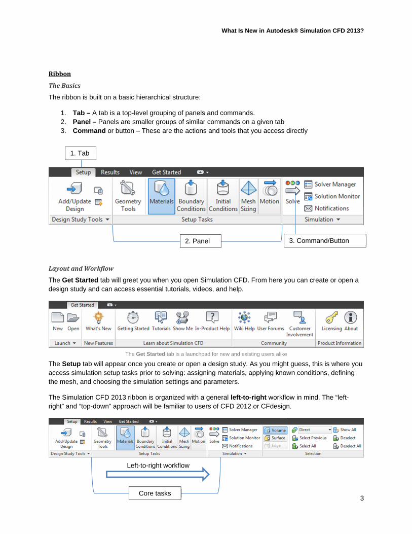
1. Tab – A tab is a top-level grouping of panels and commands. 2. Panel – Panels are smaller groups of similar commands on a given tab 3. Command or button – These are the actions and tools that you access directly
LayoutandWorkflow
The Get Started tab will greet you when you open Simulation CFD. From here you can create or open a design study and can access essential tutorials, videos, and help.
The Get Started tab is a launchpad for new and existing users alike
The Setup tab will appear once you create or open a design study. As you might guess, this is where you access simulation setup tasks prior to solving: assigning materials, applying known conditions, defining the mesh, and choosing the simulation settings and parameters.
The Simulation CFD 2013 ribbon is organized with a general left-to-right workflow in mind. The “left-right” and “top-down” approach will be familiar to users of CFD 2012 or CFdesign.
1. Tab
2. Panel 3. Command/Button
Core tasks
Left-to-right workflow
What Is New in Autodesk® Simulation CFD 2013?
4
The Results tab will become active once you solve the simulation.
The Setup and Results tabs are your home base. They are organized with the core tasks easily accessible at the center of the ribbon with secondary tasks and tools flanking them to either side.
A Context Panel (also called a merged panel) will show to the rightmost of the ribbon when any setup or results task is active. These panels can be identified by the colored title bar and their task-specific commands. Examples are shown below; note the commands are contextual to the selected task mode.
Context panels are shown to the rightmost of the ribbon.
Edit materials from the “Materials” context panel.
Add, remove, and customize results visualizations from the “Iso Surfaces” context panel.
The View tab provides access to model appearance, window display, and navigation commands. This tab is available in both setup and results for customizing appearance and window behavior. This is also where you can save and apply view settings.
The View tab is available in both setup and results mode
Core tasks
What Is New in Autodesk® Simulation CFD 2013?
5
TipsandTricks
Navigate the ribbon using keyboard shortcuts by tapping the Alt key. This will reveal “keytips” that can be used to navigate through ribbon commands using only a keyboard.
Tap the Alt key to reveal keytips. Then type the corresponding letter(s) to activate a command.
Some panels may also have panel drop-down menus that house less-used commands. Access these by clicking on the down arrow in the bottom corner of the panel title bar.
Look for the drop-down arrow on ribbon panels for additional, less-used functionality
QuickAccessToolbar
In the Simulation CFD title bar, directly adjacent to the App Menu, is the Quick Access Toolbar (QAT).
The QAT is found in the title bar and contains many of the most common commands.
The QAT is always visible and contains frequent commands like file operations, selection mode, visual style, the Decision Center, and the Selection List. This toolbar can be customized, as described below.
InfoCenter
The InfoCenter is located at the opposite end of the Simulation CFD title bar beside the window controls. This is your connection to Autodesk resources for all kinds of information and news:
Search and access help Access subscription services Product-related updates and announcements Autodesk Exchange Apps
What Is New in Autodesk® Simulation CFD 2013?
6
The InfoCenter can also be found in the title bar.
CustomizingtheInterface
While the default interface is designed to be easy and efficient out-of-the-box, you may wish to customize certain aspects. This can be useful for both advanced and novice users.
RibbonCustomization
MinimizetheRibbon
The ribbon can be minimized to increase available screen space. Cycle through the options by clicking on the arrow button in the tab title bar. You can also double click in an empty area of the dark grey title bar. To jump directly to a minimized option, click the dropdown menu beside the arrow button.
There are four options available:
Full ribbon, always visible
The full ribbon. Click the arrow to cycle through display styles
Minimize to tabs – Only the tab titles are shown. When you click on a title that ribbon tab is temporarily displayed while you select a command.
In this mode, only the tab titles are shown. Click a title to see its content.
Minimize to panel titles – The tab titles and panel titles are both shown. When you hover over a panel title its contents are displayed.
In this mode, both tab and panel titles are shown. Hover over a panel to see its content.
What Is New in Autodesk® Simulation CFD 2013?
7
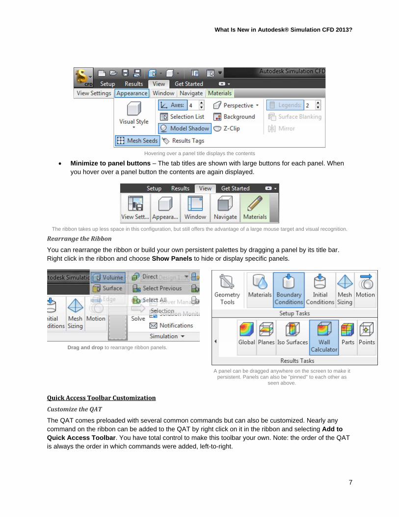
Hovering over a panel title displays the contents
Minimize to panel buttons – The tab titles are shown with large buttons for each panel. When you hover over a panel button the contents are again displayed.
The ribbon takes up less space in this configuration, but still offers the advantage of a large mouse target and visual recognition.
RearrangetheRibbon
You can rearrange the ribbon or build your own persistent palettes by dragging a panel by its title bar. Right click in the ribbon and choose Show Panels to hide or display specific panels.
Drag and drop to rearrange ribbon panels.
A panel can be dragged anywhere on the screen to make it persistent. Panels can also be "pinned" to each other as
seen above.
QuickAccessToolbarCustomization
CustomizetheQAT
The QAT comes preloaded with several common commands but can also be customized. Nearly any command on the ribbon can be added to the QAT by right click on it in the ribbon and selecting Add to Quick Access Toolbar. You have total control to make this toolbar your own. Note: the order of the QAT is always the order in which commands were added, left-to-right.
What Is New in Autodesk® Simulation CFD 2013?
8
Right click on a ribbon command to add it to the Quick Access Toolbar.
Remove commands by right clicking in the QAT and selecting Remove from Quick Access Toolbar.
To organize groups of content, right click on the QAT and choose Add Separator.
MovetheQAT
The QAT is located above the ribbon by default, but can also be displayed below the ribbon, similar to a traditional toolbar. Right click in the QAT and choose Show Quick Access Toolbar below the Ribbon.
The QAT has been moved below the ribbon to function more like a traditional toolbar.
SelectionList
The selection list is no longer enabled by default but can be accessed from the Quick Access Toolbar or the view tab.
The Selection List can be toggled on and off from the QAT button.
ClassicMode
To ease the transition from Simulation CFD 2012 to 2013, a “classic mode” is still offered in the user preferences that will revert from the ribbon-style interface to a classic CFdesign toolbar configuration.
What Is New in Autodesk® Simulation CFD 2013?
9
NewPhysicsandPerformanceImprovements
HPCAccelerant®Solver
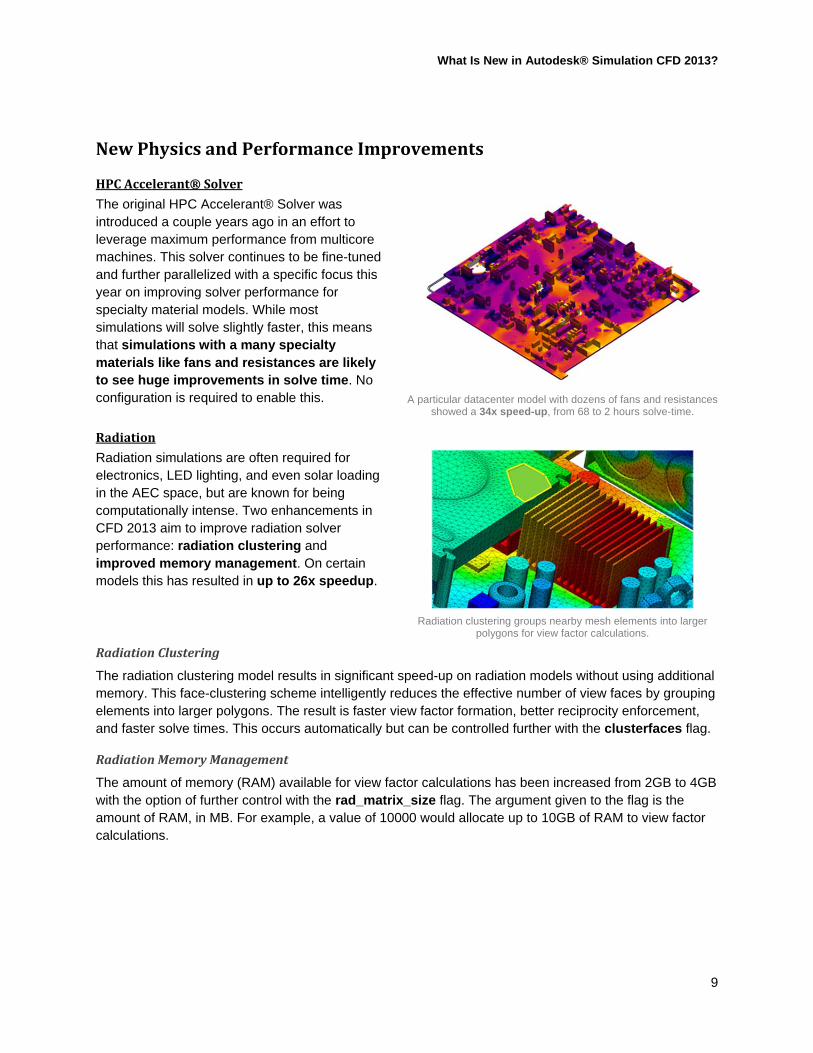
The original HPC Accelerant® Solver was introduced a couple years ago in an effort to leverage maximum performance from multicore machines. This solver continues to be fine-tuned and further parallelized with a specific focus this year on improving solver performance for specialty material models. While most simulations will solve slightly faster, this means that simulations with a many specialty materials like fans and resistances are likely to see huge improvements in solve time. No configuration is required to enable this.
A particular datacenter model with dozens of fans and resistances showed a 34x speed-up, from 68 to 2 hours solve-time.
Radiation
Radiation simulations are often required for electronics, LED lighting, and even solar loading in the AEC space, but are known for being computationally intense. Two enhancements in CFD 2013 aim to improve radiation solver performance: radiation clustering and improved memory management. On certain models this has resulted in up to 26x speedup.
Radiation clustering groups nearby mesh elements into larger polygons for view factor calculations.
RadiationClustering
The radiation clustering model results in significant speed-up on radiation models without using additional memory. This face-clustering scheme intelligently reduces the effective number of view faces by grouping elements into larger polygons. The result is faster view factor formation, better reciprocity enforcement, and faster solve times. This occurs automatically but can be controlled further with the clusterfaces flag.
RadiationMemoryManagement
The amount of memory (RAM) available for view factor calculations has been increased from 2GB to 4GB with the option of further control with the rad_matrix_size flag. The argument given to the flag is the amount of RAM, in MB. For example, a value of 10000 would allocate up to 10GB of RAM to view factor calculations.
What Is New in Autodesk® Simulation CFD 2013?
10
HeatExchangerModel
A new material model has been introduced for simulating several types of heat exchangers commonly found in AEC, data center, and other architectural applications. This model can be used to approximate:
Heater or a chiller devices in HVAC, AEC, and architectural environments Computer Room Air Conditioner (CRAC) units Computer Room Air Handler (CRAH) Computer Air Conditioner (CAC) Air to Air coolers Liquid Coolers Air Conditioners
The complex physics of these devices can now be represented with a simple geometric model along with a few flow and thermal parameters that are defined in the CFD material properties.
UsingaHeatExchanger
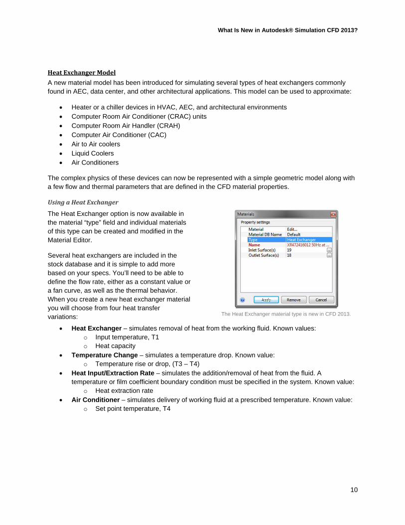
The Heat Exchanger option is now available in the material “type” field and individual materials of this type can be created and modified in the Material Editor.
Several heat exchangers are included in the stock database and it is simple to add more based on your specs. You’ll need to be able to define the flow rate, either as a constant value or a fan curve, as well as the thermal behavior. When you create a new heat exchanger material you will choose from four heat transfer variations:
The Heat Exchanger material type is new in CFD 2013.
Heat Exchanger – simulates removal of heat from the working fluid. Known values: o Input temperature, T1 o Heat capacity
Temperature Change – simulates a temperature drop. Known value: o Temperature rise or drop, (T3 – T4)
Heat Input/Extraction Rate – simulates the addition/removal of heat from the fluid. A temperature or film coefficient boundary condition must be specified in the system. Known value:
o Heat extraction rate Air Conditioner – simulates delivery of working fluid at a prescribed temperature. Known value:
o Set point temperature, T4
What Is New in Autodesk® Simulation CFD 2013?
11
HeatExchangerGuidelines
If there are multiple heat exchangers in your simulation assign each one individually Do not assign boundary conditions to the heat exchanger part The heat exchanger should be connected to the system only by its inlets and outlets The heat exchanger inlet and outlets should be separately selectable planar surfaces If it is not feasible to build the heat exchanger outside of the system, place the heat exchanger
model inside the actual [CRAC] unit and suppress the body around it such that the heat exchanger, when meshed, is only contacting the surrounding system through the inlet and outlet.
This model is not intended to simulate open-loop systems A uniform pressure condition is automatically applied to the heat exchanger inlet. This can result
in non-physical behavior if the heat exchanger must be located in a pressurized area. In this case try the inlet_is_vol_flow_bc flag.
An example of a heat exchanger setup in CFD 2013. Note the air extensions as heat exchanger inlet and outlet.
T3
T2
q
T4
T1
SYSTEM
HEAT
EXCHANGER
HX Inlet/System Outlet
HX Outlet/System Inlet
HEAT EXCHANGER
SYSTEM
What Is New in Autodesk® Simulation CFD 2013?
12
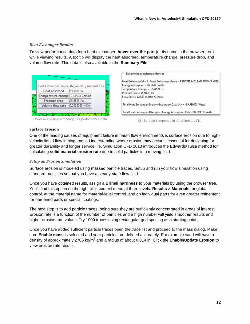
HeatExchangerResults
To view performance data for a heat exchanger, hover over the part (or its name in the browser tree) while viewing results. A tooltip will display the heat absorbed, temperature change, pressure drop, and volume flow rate. This data is also available in the Summary File.
Hover over a heat exchanger for performance data. Similar data is reported in the Summary File.
SurfaceErosion
One of the leading causes of equipment failure in harsh flow environments is surface erosion due to high-velocity liquid flow impingement. Understanding where erosion may occur is essential for designing for greater durability and longer service life. Simulation CFD 2013 introduces the Edwards/Tulsa method for calculating solid material erosion rate due to solid particles in a moving fluid.
SetupanErosionSimulation
Surface erosion is modeled using massed particle traces. Setup and run your flow simulation using standard practices so that you have a steady-state flow field.
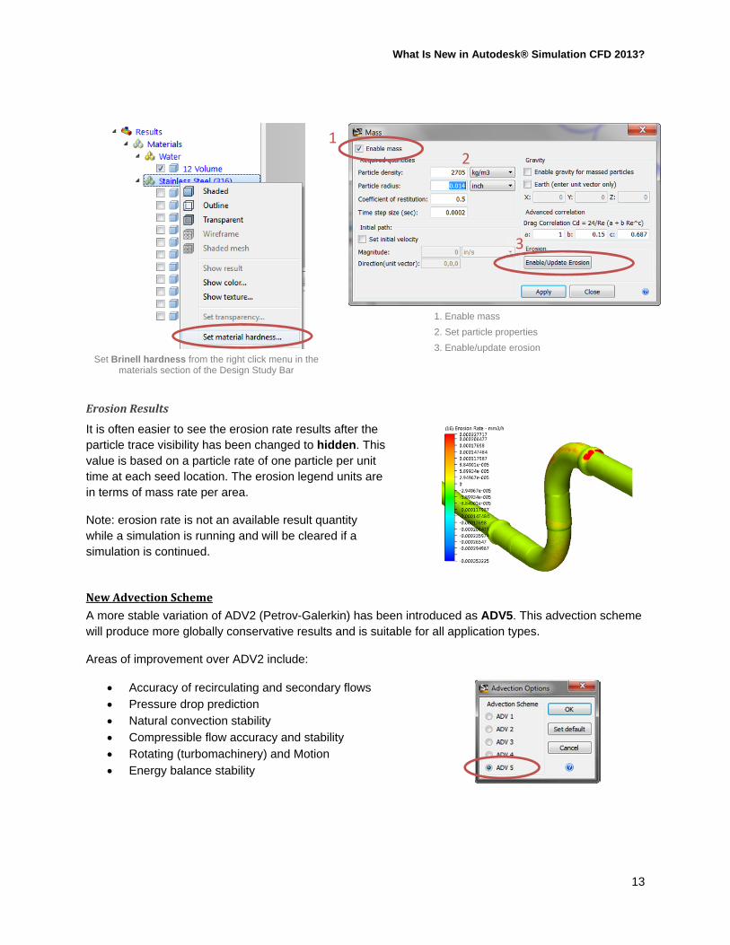
Once you have obtained results, assign a Brinell hardness to your materials by using the browser tree. You’ll find this option on the right click context menu at three levels: Results > Materials for global control, at the material name for material-level control, and on individual parts for even greater refinement for hardened parts or special coatings.
The next step is to add particle traces, being sure they are sufficiently concentrated in areas of interest. Erosion rate is a function of the number of particles and a high number will yield smoother results and higher erosion rate values. Try 1000 traces using rectangular grid spacing as a starting point.
Once you have added sufficient particle traces open the trace list and proceed to the mass dialog. Make sure Enable mass is selected and your particles are defined accurately. For example sand will have a density of approximately 2705 kg/m3 and a radius of about 0.014 in. Click the Enable/Update Erosion to view erosion rate results.
What Is New in Autodesk® Simulation CFD 2013?
13
Set Brinell hardness from the right click menu in the materials section of the Design Study Bar
1. Enable mass
2. Set particle properties
3. Enable/update erosion
ErosionResults
It is often easier to see the erosion rate results after the particle trace visibility has been changed to hidden. This value is based on a particle rate of one particle per unit time at each seed location. The erosion legend units are in terms of mass rate per area.
Note: erosion rate is not an available result quantity while a simulation is running and will be cleared if a simulation is continued.
NewAdvectionScheme
A more stable variation of ADV2 (Petrov-Galerkin) has been introduced as ADV5. This advection scheme will produce more globally conservative results and is suitable for all application types.
Areas of improvement over ADV2 include:
Accuracy of recirculating and secondary flows Pressure drop prediction Natural convection stability Compressible flow accuracy and stability Rotating (turbomachinery) and Motion Energy balance stability
2
3
1
What Is New in Autodesk® Simulation CFD 2013?
14
FullyDevelopedBoundaryConditionProfile
A new boundary condition option for velocity and volume flow rate has been introduced to simulate fully developed flow at an inlet. Previously these boundary conditions were always given a uniform flow profile. The fully developed profile is generally more physically realistic and eliminates the need to add extensions upstream of the inlet for developing the flow (they still may be needed for other reasons).
The fully developed flow option is available for circular, triangular, and quadrilateral planar surfaces.
Enable fully developed flow on the Boundary Condition quick edit dialog
For a circular inlet, fully developed flow profile (left) vs. uniform flow profile (right).
Multi‐threadedMeshing
While still somewhat experimental, groundwork has been laid for multithreaded meshing in order to take better advantage of multi-core machines. This functionality is enabled with the mesh_multicore flag; the argument given to the flag will specify the max number of cores to be used by the mesher.
This is not without limitation. Multi-threaded meshing will not work for models launched from Pro/Engineer with the Mechanica option. It also does not support “volume growth rate” and “boundary layer blending” options from the advanced control dialog. Extruded elements will continue to be generated serially.
Test models, like the valve above, exhibit ~2x speedup using standard engineering desktop computers.
What Is New in Autodesk® Simulation CFD 2013?
15
AutomationofRepetitiveTasks
MeshAdaptation
Mesh adaptation represents the next advance in meshing technology for Simulation CFD. When this option is enabled, simulation results are used to iteratively improve the mesh definition resulting in a more appropriate mesh for the unique physics of a given system. In other words, the simulation will run multiple successive cycles using the results from the previous cycle to selectively refine the mesh in the following cycle in areas of high velocity, pressure, and temperature gradients.
To enable mesh adaptation, simply navigate to the adaptation tab of the solve dialog and check the box. Here you can also select the number of cycles to run in addition to the baseline, which defaults to three (for a total of four runs). Each cycle will run the prescribed number of iterations, or to convergence; we recommend 300 iterations for most applications.
Enabling save cycles will cause the scenario to be cloned at the conclusion of each cycle, preserving the mesh and results in a separate scenarios; this makes it easy to inspect the iterative mesh and result progression using the Decision Center.
It’s also worth noting that by default the mesh will only be refined by mesh adaptation. The allow coarsening option is self-explanatory and can be used to prevent
the mesh from growing too large by coarsening areas that have been over-meshed in the baseline scenario.
Enable adaptation from the solve dialog.
Limitations
Mesh adaptation is not an excuse to slack on the baseline mesh setup and hope the computer will spit out something good. Standard best practices should still be employed to ensure a good starting point that captures the characteristic behavior of the system. Also note that since multiple cycles are being run serially this approach will take longer than a scenario run without adaptation – the element count will also increase based on the nature of the adaptation process.
The following scenarios cannot be adapted in CFD 2013:
Transient simulations Quick convection simulations 2D simulations 3D simulations containing 2D surface parts Extruded meshes Pro/Engineer Mechanica-launched models Certain specialty materials: distributed resistances, internal fan, centrifugal pump, check valve,
rotating region, compact thermal model (CTM), thermoelectric device (TEC), and LEDs.
What Is New in Autodesk® Simulation CFD 2013?
16
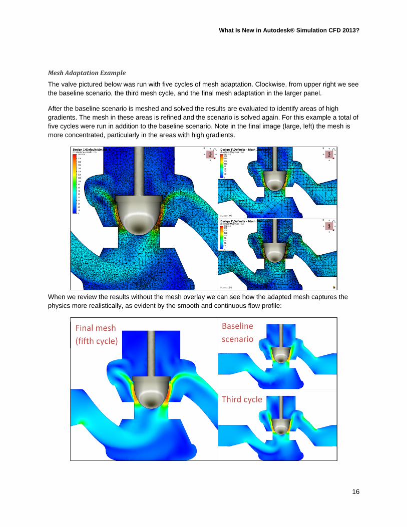
MeshAdaptationExample
The valve pictured below was run with five cycles of mesh adaptation. Clockwise, from upper right we see the baseline scenario, the third mesh cycle, and the final mesh adaptation in the larger panel.
After the baseline scenario is meshed and solved the results are evaluated to identify areas of high gradients. The mesh in these areas is refined and the scenario is solved again. For this example a total of five cycles were run in addition to the baseline scenario. Note in the final image (large, left) the mesh is more concentrated, particularly in the areas with high gradients.
When we review the results without the mesh overlay we can see how the adapted mesh captures the physics more realistically, as evident by the smooth and continuous flow profile:
Baseline
scenario
Third cycle
Final mesh
(fifth cycle)
What Is New in Autodesk® Simulation CFD 2013?
17
We can further plot critical values for each scenario to ensure that as the adaptation progresses we are approaching mesh independence. Starting with the baseline scenario (“Mesh 1”) we can see that the results are quite mesh dependent and unstable for the first two cycles, but begin to converge around 0.31 psi as the adaptation progresses. Depending on other criteria we may consider running only three or four adaptations for similar valve setups in the future since our critical pressure achieves mesh independence around this point:
Critical pressure plotted as a summary point for a mesh adaptation run.
Baseline scenario
Final M
esh
What Is New in Autodesk® Simulation CFD 2013?
18
MeshHistory
Now when you define your mesh setup the steps are tracked automatically in the Design Study Bar.
This not only increases the visibility of actions for future reference, but makes updates and changes to the mesh definition a snap. Changing a refinement, for example, is as simple as entering a new refinement factor and rebuilding the definition – the other steps in the process are automatically preserved. Steps can also be excluded simply by unchecking them.
You’re likely to see big gains from this feature when you have multiple designs and want to recreate the same or similar mesh on a different model. It can also be leveraged in mesh independence studies for quickly varying critical refinements.
RefinementRegionParameters
Prior to CFD 2013 the setup of mesh regions was approximate. Now location and size parameters are fully exposed for exact and repeatable placement. This is also coupled with the mesh history to enable exact modification of refinement regions after initial assignment.
ParticleTraceSeeding
To assist in particle trace seeding a new use grid spacing option has been added to the rectangular grid method. This option allows the vector density grid to define the particle seed points.
1 - Refine vector grid spacing to desired density on the plane settings dialog
2 - Enable "use grid spacing" for rectangular seeding method
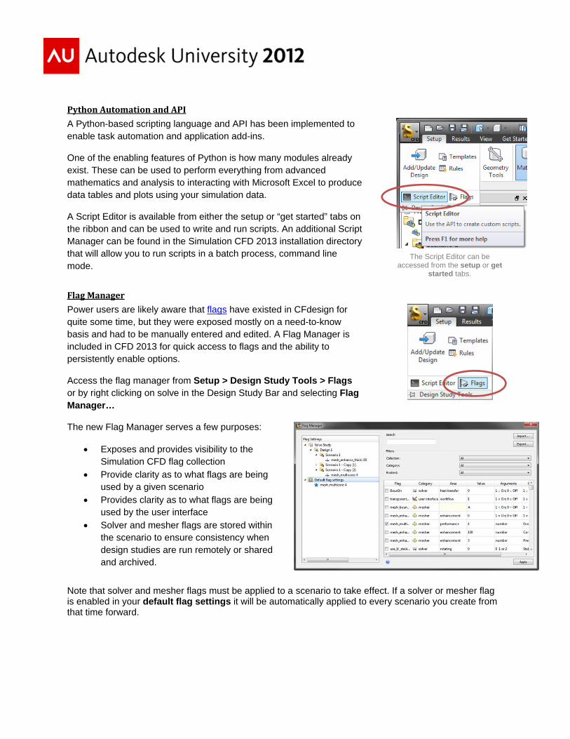
PythonAutomationandAPI
A Python-based scripting language and API has been implemented to enable task automation and application add-ins.
One of the enabling features of Python is how many modules already exist. These can be used to perform everything from advanced mathematics and analysis to interacting with Microsoft Excel to produce data tables and plots using your simulation data.
A Script Editor is available from either the setup or “get started” tabs on the ribbon and can be used to write and run scripts. An additional Script Manager can be found in the Simulation CFD 2013 installation directory that will allow you to run scripts in a batch process, command line mode.
The Script Editor can be accessed from the setup or get
started tabs.
FlagManager
Power users are likely aware that flags have existed in CFdesign for quite some time, but they were exposed mostly on a need-to-know basis and had to be manually entered and edited. A Flag Manager is included in CFD 2013 for quick access to flags and the ability to persistently enable options.
Access the flag manager from Setup > Design Study Tools > Flags or by right clicking on solve in the Design Study Bar and selecting Flag Manager…
The new Flag Manager serves a few purposes:
Exposes and provides visibility to the Simulation CFD flag collection
Provide clarity as to what flags are being used by a given scenario
Provides clarity as to what flags are being used by the user interface
Solver and mesher flags are stored within the scenario to ensure consistency when design studies are run remotely or shared and archived.
Note that solver and mesher flags must be applied to a scenario to take effect. If a solver or mesher flag is enabled in your default flag settings it will be automatically applied to every scenario you create from that time forward.
What Is New in Autodesk® Simulation CFD 2013?
20
Interoperability
RevitConnection
Models imported from Revit will now preserve family information as well as parametric associativity. This applies to Revit Architecture and MEP.
You will now find that when you import a Revit model into Simulation CFD 2013 that family categories, family names, and types will be preserved as part names in CFD. Aside from making things more recognizable and consistent between the two environments this also enables the use of rules in CFD to automatically assign of materials and conditions to components as models are imported.
Family information is now imported directly from the Revit model allowing the use of rules in Simulation CFD.
Additionally, improved parametric associativity means that settings are maintained more reliably when geometry is changed and updated in design studies. This leads to less “lost” materials and boundary conditions.
FusionConnection
The Inventor Fusion connection has been updated with the release of Simulation CFD 2013 to include simulation simplification and setup tools, and also to support model associativity. Like the improvements for Revit, this means settings are maintained more reliably when geometry is changed and updated.
The following tools will assist with simulation model simplification and setup:
Interference detection – the interference command analyzes a set of components for interferences that can be troublesome downstream in simulation. Interferences often lead to meshing errors and at a minimum can unnecessarily increase element counts.
Model simplification– use these tools to remove small features from CAD models that cause unnecessary complexity in the simulation model. Fusion now has options to remove fillets, chamfers, and holes within a given size threshold. These features often have little to no effect on simulation results, but cause the solve time to increase due to the additional elements required to capture them.
Fluid volume tool – this tool allows you to create the internal fluid volume that is necessary for flow simulations. This can still also be done within Simulation CFD but Fusion adds the option to create the fluid volume quickly and easily in CAD for greater modeling control.
What Is New in Autodesk® Simulation CFD 2013?
21
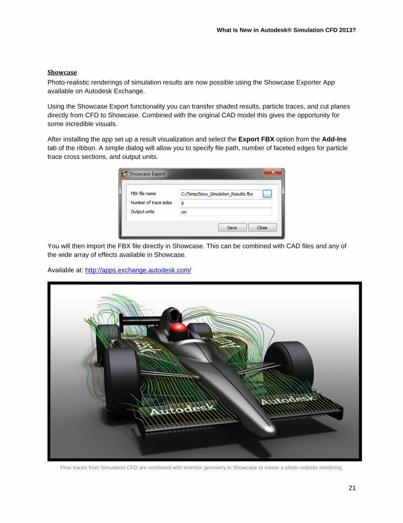
Showcase
Photo-realistic renderings of simulation results are now possible using the Showcase Exporter App available on Autodesk Exchange.
Using the Showcase Export functionality you can transfer shaded results, particle traces, and cut planes directly from CFD to Showcase. Combined with the original CAD model this gives the opportunity for some incredible visuals.
After installing the app set up a result visualization and select the Export FBX option from the Add-Ins tab of the ribbon. A simple dialog will allow you to specify file path, number of faceted edges for particle trace cross sections, and output units.
You will then import the FBX file directly in Showcase. This can be combined with CAD files and any of the wide array of effects available in Showcase.
Available at: http://apps.exchange.autodesk.com/
Flow traces from Simulation CFD are combined with Inventor geometry in Showcase to create a photo-realistic rendering.