Operating Mode Buttons o Introduction of additional operation mode “TEST”
Engine Start Stop Buttons
“Home” Button functionality
Base Models
EG3200XT-P1 (EG3100XT-P1)
EG3500XT-P1 (EG3400XT-P1)
EG3500XT-P2 (EG3400XT-P2)
Low temperature (-40°C) display versions are available
Terminals
The phoenix plugs remain mainly the same with some slightly changes: o The 100V AC measurement is connected on the 400V connection (the 100V AC
connection does not exist anymore)
Version 1.0 w w w . w o o d w a r d . c o m 3
o The analog outputs 1 & 2 are supported with two terminals now (the shunt for voltage output is internally populated)
o The engine ground is moved now from terminal 62 to terminal 15
The 9-pin D-sub connectors are replaced by phoenix plugs with screw terminals
I/O Features
The DC analog inputs 1-3 supporting as restive input now senders within 0-2 kOhms. (The current easYgen 500 Ohms)
The DC analog inputs 1-3 supporting additionally 0-1V senders. (An use case would be for example the shunting of mains CTs outside and measure the voltage over the shunt)
CT inputs: 1A and 5A secondary are provided by one P/N
CT inputs: The maximum power consumption is reduced under 0.1VA (The current easYgen 0.15VA)
Discrete Inputs: The minimum delay time of DIs on board are now 20ms (The current easYgen supports 80ms)
The DC analog output 2: The output is equipped with a higher isolation capability against ground. (preferred for AVR biasing)
EG3500XT: The AC voltage measurement is expanded to 690 Vrated
EG3500XT-P2: 6 DC analog outputs are provided (The current easYgen 3500P2 supports 5 DC AO)
EG3500XT-P2: The busbar measurement is provided with 3 AC voltages
Communication Interfaces
The RS232 is removed by USB (slave) connection
Additional 1 Ethernet connection A is provided
EG3500XT: additional 2 other Ethernet connections B,C (redundant Ethernet) is provided
Version 1.0 w w w . w o o d w a r d . c o m 4
Functionality
Measurement
The AC voltage measurement is increased to 0.5% (class 0.5)
The AC current measurement is increased to 0.5% (class 0.5)
The AC power measurement is increased to 1% (class 1)
EG3500XT: The AC Measurement up to 690V rated is supported
EG3500XT-P2: The busbar measurement can be executed with all three phases o Dead busbar recognition of 3 phases o Phase rotation detection of busbar o 3 phase monitoring busbar
HMI
The “Home Screen” Button guides you always back to the overview starting point.
Version 1.0 w w w . w o o d w a r d . c o m 5
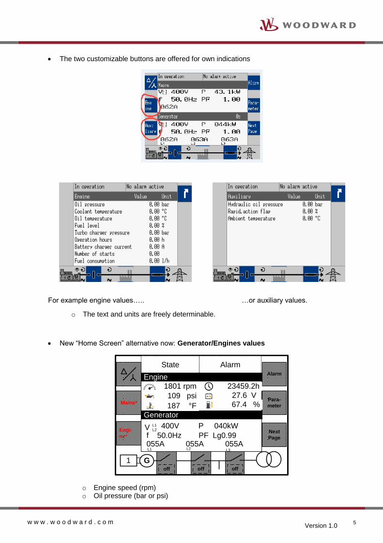
The two customizable buttons are offered for own indications
For example engine values….. …or auxiliary values.
o The text and units are freely determinable.
New “Home Screen” alternative now: Generator/Engines values
Mains*
Engi-
ne*
Alarm
Para-
meter
Next
Page
State Alarm
G1off offoff
Generator
1801 rpm
109 psi
f 50.0Hz PF Lg0.99055A 055A 055A
400V P 040kWV L1
L2
L3L1 L2
187 °F
23459.2h
67.4 %
27.6 V
Engine
o Engine speed (rpm) o Oil pressure (bar or psi)
Version 1.0 w w w . w o o d w a r d . c o m 6
o Water temperature (°C or °F) o Operating hours (h) o Battery voltage o Fuel level (%)
The engine values indication layout is fixed. The sources of the values (e.g. AI or J1939)
are configurable by AnalogManager.
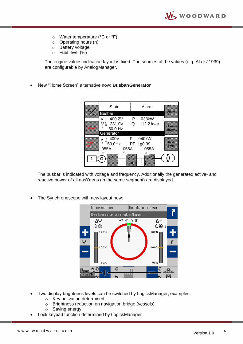
New “Home Screen” alternative now: Busbar/Generator
Mains*
Engi-
ne*
Alarm
Para-
meter
Next
Page
State Alarm
G1off offoff
Busbar
Generator
400.2V P 038kW
231.0V Q -12.2 kvar
f 50.0 Hz
f 50.0Hz PF Lg0.99
055A 055A 055A
V L
L
400V P 040kWV L1
L2
L3L1 L2
V L
N
The busbar is indicated with voltage and frequency. Additionally the generated active- and
reactive power of all easYgens (in the same segment) are displayed.
The Synchronoscope with new layout now:
Two display brightness levels can be switched by LogicsManager, examples: o Key activation determined o Brightness reduction on navigation bridge (vessels) o Saving energy
Lock keypad function determined by LogicsManager
Version 1.0 w w w . w o o d w a r d . c o m 7
Operation Modes
The easYgen3000XT provides now additionally a “TEST” mode:
The TEST mode
The TEST mode shall give the operator the opportunity to test the genset. Different modes are
configurable:
o Off o Test Run without load, not time restricted o Test Run without load, time restricted o Test Run with load, not time restricted o Test Run with load, time restricted o Test Run with breaker access, not time restricted
When the Test Run is time restricted, the remaining time is displayed on HMI.
A time restricted Test mode can be configured so that the device changes its operating mode after
execution the TEST run.
In TEST mode the breakers are operated like in the application mode configured.
In Test mode the momentarily activated AUTOMATIC setpoints are used.
Version 1.0 w w w . w o o d w a r d . c o m 8
The emergency run (AMF) and the sprinkler run is fully supported, if configured.
Load Dependent Start Stop (LDSS)
The LDSS provides now with the parameter "ID5755 Fit operating hours" another enumeration:
o Off o Equal maintenance o Staggered maintenance o Period of use hours
The period of use hours is a dedicated operating hour counter. This counter can be
individually set and reset and is independent on the engine operating hours counter.
With choosing the mode “Period of use hours” the engines are started and stopped in
regards to this counter. The maintenance counter has here no influence anymore.
Switchable Reserve power: o 2 configurable reserve power settings in mains parallel mode o 2 configurable reserve power settings in isolated operation mode
The switching over from one reserve power level to the other is done by
LogicsManager equations.
Introduction of a new parameter: LDSS sort priority always Yes/No: This setting determines whether the engines shall be always sorted in case of
operation time group, priorities and device number or to do this only in cases when a
load situation is causing an engine change anyway.
No: The sorting in regards of operation time groups, priority and device number is
executed only, if the load situation causes a new engine constellation anyway.
Yes: The sorting in regards of operation time groups, priority and device number is
executed always.
Engine Control
The speed and firing speed detection is now individually configurable:
In the current easYgen the firing speed and the speed detection is always determined
by the electrical frequency measurement. This cannot be influenced.
In the easYgen3000XT the firing speed and the speed detection is now managed by
LogicsManager equations named “Firing speed detection” and “Speed detection”. The
Version 1.0 w w w . w o o d w a r d . c o m 9
default setting of them is doing the same like the current easYgen. The advantage now
is to have more flexibility to arrange different sources to determine speed and firing
speed.
Engine Monitoring
Operating Range Monitoring: The different cases for operating range failures are displayed with an Error Code (001,
002, …). The failure cases are to complicate to explain it in a 20 character alarm
prompt. The operating manual clearly explains what is wrong.
Load share mismatch Monitoring: Like in the easYgen3000 marine the active and reactive load sharing can be
individually monitored.
Engine Period of use hours
The unit provides an additional counter for operating hours independent on the
actually operating hour counter of the engine. This counter is usable for additional
functions, like for rental or LDSS purposes.
The displayed format is 000000.00 h. The counter is available as AnalogManager
variable, can be displayed in the HMI and is available on interface protocol. The
counter can be set and reset.
Load sharing
The load sharing is supported in different ways:
o CAN: All easYgens communicating over CAN. (easYgen3200XT CAN1; easYgen3500XT CAN3)
o Ethernet A: All easYgens communicating over Ethernet A o Ethernet B/C: EG3500XT: The easYgens communicating over Ethernet B and
C the redundancy and its monitoring is incorporated.
Generator Monitoring
Sync Check Relay Function:
The easYgen provides an independent Synchronize Check Relay Generator <->
Busbar. The criteria are the same like for the active synchronizer without breaker
related closing time compensation. The function is usable over a LogicsManager
command flag.
Version 1.0 w w w . w o o d w a r d . c o m 10
Busbar Monitoring
Busbar Monitoring in Voltage and Frequency: The Busbar monitoring compares the actual voltage and frequency of the busbar with
the configured generator operating ranges. If this protective function is triggered, the
display indicates "Busbar v/f not ok".
This monitoring function can be taken to monitor and alert, if the operating range of the
generator does not match with the busbar measurement. This is interesting in
application where the condition of the busbar has a high priority and fast actions must
be performed to avoid black outs of the system.
Busbar Phase Sequence (Phase Rotation): EG3500XT-P2: To prevent miss-wired connections in mobile applications the busbar
phase sequencing can be detected to induce according actions.
Version 1.0 w w w . w o o d w a r d . c o m 11
Breaker Operation
EG3500XT: The Generator Group Breaker (GGB) is operate-able now by soft-key:
The GGB can be operated by soft-key
EG3500XT-P2: Phase rotation mismatch diagnostic
G3~
GCBPhase Rotation
MismatcheasYgen3500
P2
MCBPhase Rotation
Mismatch
Through the capability measure the phase rotation of the busbar in the
easYgen3500XT-P2 a sophisticated phase rotation diagnostic can be executed
between mains and busbar as between busbar and generator to induce according
actions.
Version 1.0 w w w . w o o d w a r d . c o m 12
General Monitoring Features
The parameter “Delayed by engine speed” Yes/No is now replaced by the parameter “Enabled” in each monitoring configuration.
The parameter “Enabled” determines when the monitoring is enabled. Two settings
are possible:
- Always: The monitoring is always enabled
- 87.70 LM:Eng.mon: The monitoring is executed, if the LogicsManager “Release
engine monitoring” is TRUE and the monitoring delay time
is expired.
The default setting of the LogicsManager “Release Engine Monitoring” is executed
according to the “Delayed by engine speed” configuration.
The introduction of this method seems to be a little bit confusing but it follows a clear
rule and should be easy to learn. The advantage of this method is now that it offers
more flexibility in the future. So it is planned to introduce soon other enumerations for
the “Enabled” setting.
Version 1.0 w w w . w o o d w a r d . c o m 13
Expanded List of events for the data logger o TEST mode o Mains failure o GGB open o GGB close o Open command GCB o Close command GCB o Open command MCB o Close command MCB o Open command GGB o Close command GGB o Test without load o Test with load o Engine Idle run
The entries maintenance days exceeded and maintenance hours exceeded are not
longer treated as fixed entries. Their entry depends on the alarm management.
Introduction of 16 freely configurable alarms The easYgen offers from now on 16 freely configurable alarms, with:
o Alarm text o LogicsManager activation o Alarm class o Self acknowledge o Enabled o Delay time
Flexible thresholds The threshold and hysteresis entry is executable in an expansion format between
-21000.00e3 … 21000.00e3
This setting range enables to handle all float variables coming from the
AnalogManager system.
Version 1.0 w w w . w o o d w a r d . c o m 14
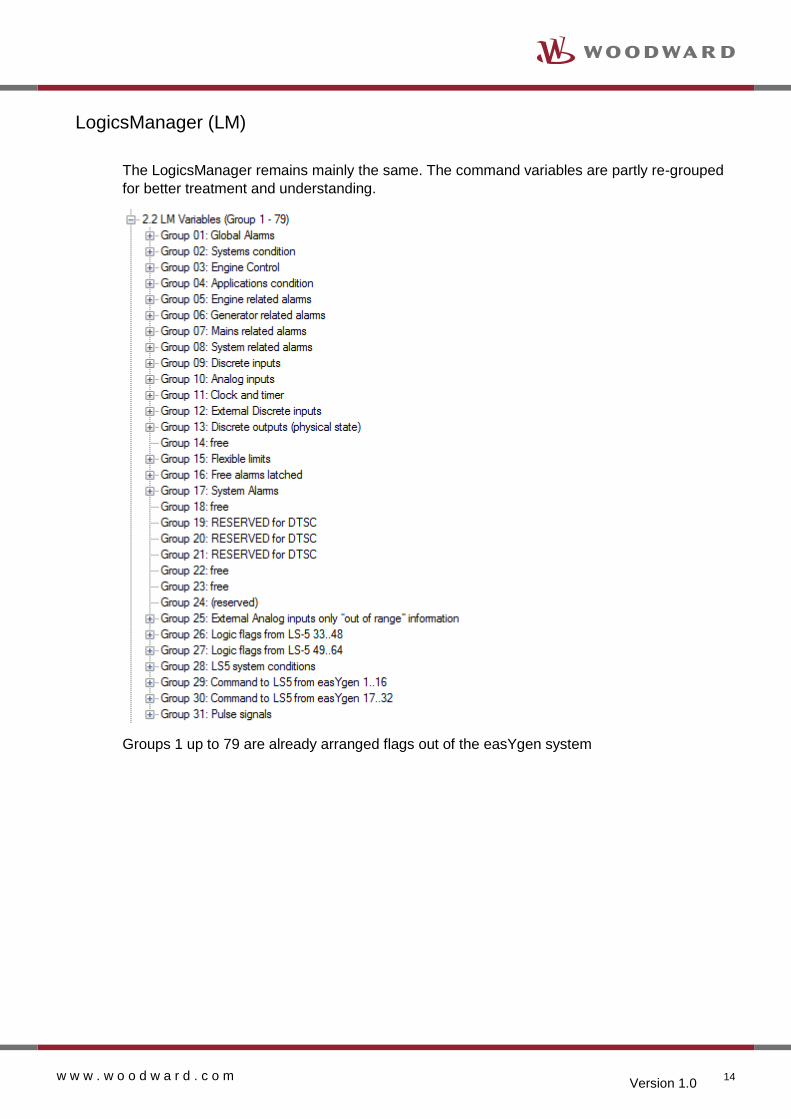
LogicsManager (LM)
The LogicsManager remains mainly the same. The command variables are partly re-grouped
for better treatment and understanding.
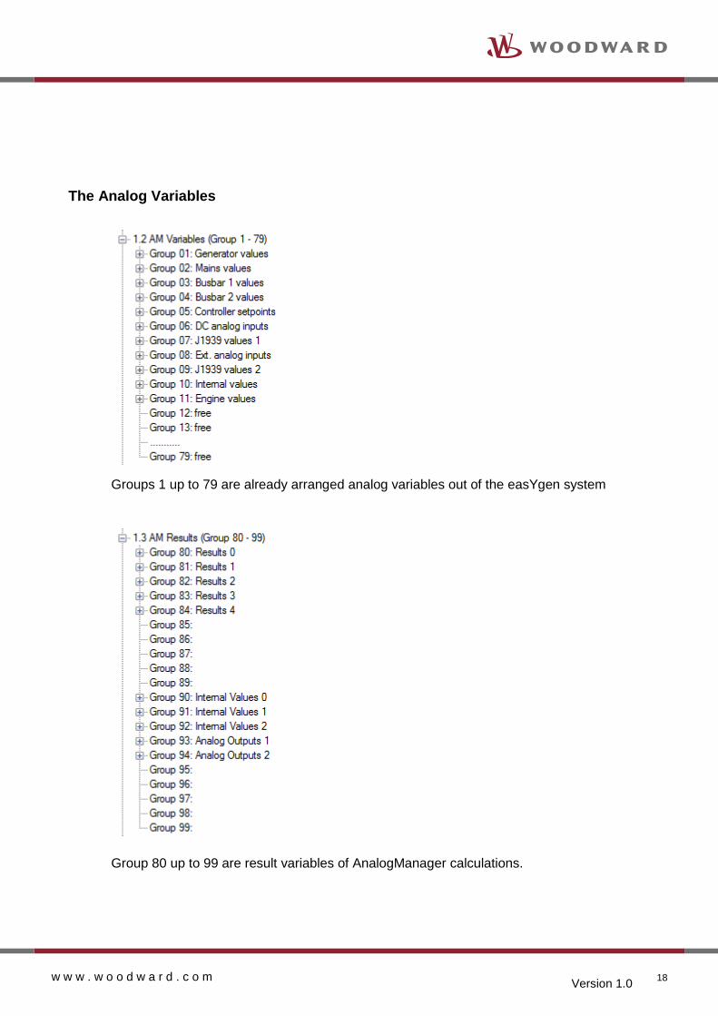
Groups 1 up to 79 are already arranged flags out of the easYgen system
Version 1.0 w w w . w o o d w a r d . c o m 15
Group 80 up to 99 are containing flags, which are results of LogicsManager equation or
AnalogManager calculations.
AnalogManager (AM)
General
Example: Calculating with an AnalogManager
Version 1.0 w w w . w o o d w a r d . c o m 16
Example: Incrementing and compare with an AnalogManager
The AnalogManager can be fed with up to 2 analog variables in conjunction with 2
Boolean information and a direct configurable constant. Out of this, together with a
deposited function, the AM provides a result in form of an analog value and a Boolean.
If it is a freely usable AM, the analog result is accessible via the AnalogManager
command variable pool.
If it is a dedicated AM, the analog result is directly accepted by an according function
(e.g. AO1) and additionally accessible via the AnalogManager command variable pool.
The resulting Boolean is accessible via the LogicsManager command variable pool.
Operations
Pass through
Constant
Summation
Subtraction
Limit Switch
Compare with delay on
Multiply Type A
Multiply Type B
Multiply Type C
Divide
Switch
Maximum
Minimum
In Band
Ramp
Filter
Increment
Latch
Timer
Maxtrack
Mintrack
Delay Type A
Delay Type B
Toggle
One Shot
Version 1.0 w w w . w o o d w a r d . c o m 17
The Operation Bitmaps
3. Summation5. Limit
Switch4. Subtraction1. Pass Through 2. Constant
Res
Limit
Switch
Mode
Hyst
A1-A2
A1
A2
F1
B1
B2
6. Compare
with Delay On7. Multiply
Type A
8. Multiply
Type B
11. Switch 12. Maximum 13. Minimum 14. In Band 15. Ramp
USB connection substitutes the former RS232 connection
Version 1.0 w w w . w o o d w a r d . c o m 20
The easYgen3500XT offers 3 Ethernet ports A, B, C:
CAN #2CAN Bus Engine
Level
Toolkit
USB
Genset Control
EG3500XT
Ethernet #A
PLC
Mo
db
us /
TC
P
Toolkit
Se
rvlin
k /T
CP
Remote
Panel
CAN #1
PLC
RS485
PLC
ECU
I/O
Modules
CAN #3
LS-5
Ethernet #B Ethernet #C
Load Share Information
Load Share Information
Redundant Load share Lines
EG3200XT – Interface arrangement
Ethernet port A supports: Remote Panel Connection PLC Connection (Modbus TCP) Load share Connection Toolkit Connection
Ethernet port B and C support: Redundant Load share Connection PLC Connection (Modbus TCP)
USB connection substitutes the former RS232 connection
Version 1.0 w w w . w o o d w a r d . c o m 21
Protocols
The Software protocols 5003, 5004, 5005, 5010 and 5011 are still offered and are the same like in the current easYgen3000 device. Because of compatibility reasons their contents is not changed nor is something added.
A new protocol 5014 is introduced. o It is based on the 5003 with a restricted set of ECU J1939 contents o It is accessible by CANopen and Modbus commands o It contains additional values in regards to the EG3000XT new feature set o The CANopen repeat rate for a 20ms TPDO is 1.5 seconds.
RS485
The RS485 Modbus RTU connection is now supported in a 20ms time frame. Large latency
periods (up to 1.2 seconds in the current easYgen) are not possible anymore.
CAN3
The CAN3 bus supports now ToolKit connection. This gives now the capability to connect
Toolkit on the CAN3 load share bus and enables one Toolkit Access point for all controls (LS-5
and easYgen) at one connection point.
ToolKit
easYgen3500XT
IXXAT
USB to CAN
CAN3
LS-5
One connection point for Toolkit on the CAN3 bus makes the commissioning more
comfortable.
Version 1.0 w w w . w o o d w a r d . c o m 22
Communication Management
General
The easYgen3000XT provides now a load share communication management which cares
about the communication functionality (sustainability) in regards to the whole system.
The easYgen3000XT monitors the system communication network so that the operator is
informed, if the network is not running properly. In failure cases where no communication
redundancy is available proper actions can be triggered immediately (e.g. “Missing member
failure” leads to a droop function).
The monitoring of the system communication network is easily adaptable to the intended
system by a "system update" order.
The operator shall be able to teach the whole system for the new topology (I.e. a control is
powered off).
The easYgen provides an overview screen to check the system communication. It helps to
detect as good as possible where the failure is located (the root cause).
The communication management is usable for different system busses and is activated on the
current configured load share bus:
Load share on CAN1 network
Load share and LS-5 on CAN3 network (EG3500XT)
Load share on Ethernet A network
Load share on Ethernet B,C network (EG3500XT)
The System Update Procedure
The system update procedure is teaching all connected easYgens on the network to accept
the momentary bus constellation as the “health” condition. This procedure is executed by an
operator (or commissioner) who has the overview over the whole network. The easYgens are
supporting him by indicating all recognized member in the display.
The System update process is started by energizing either the LM "System update" or by
using an On/Off parameter in ToolKit and HMI (Located in the System Overview page).
The device at which the system update is initiated sends a System update request for 30
seconds to all members on the system bus.
During this time all members disable its member monitoring function and listen which
members are momentarily actively participating. This condition will be fixed within of this 30
second period and the current number of members will be stored for the missing member
monitor in each control.
After this 30 seconds the member monitoring is enabled again.
The number of accepted easYgens is displayed for evaluating in the overview screens of HMI
and Toolkit. A PLC can access on this number also.
Version 1.0 w w w . w o o d w a r d . c o m 23
The update process includes the LS-5 units as well. The overview screens in the HMI and
Toolkit treating easYgens and LS-5s separately.
The number of accepted LS-5 devices is displayed for evaluating in the according overview
screens of HMI and Toolkit.
I/O Expansion Boards
The full expansion board capability (same like EG3200P2 and EG3500P1) is now included in all easYgen3000XT models.
J1939 devices
The J1939 devices like for example ECU or I/O boards (Axiomatic) are now separately monitored. Up to 4 devices can be supervised now with independent delay times and alarm classes.
“THE INFORMATION CONTAINED IN THIS DOCUMENT IS PROVIDED AS IS WITHOUT REPRESENTATIONS OR WARRANTIES OF
ANY KIND EXPRESSED OR IMPLIED. THE ADHERENCE TO THE INFORMATION CONTAINED IN THIS DOCUMENT SHALL BE AT
THE USER’S OWN RISK. WOODWARD EXPRESSLY DISCLAIMS ANY REPRESENTATIONS OR WARRANTIES CONCERNING
WHETHER THE DELIVERABLES, OR SOFTWARE WILL PRODUCE ANY SPECIFIC RESULT OR PERFORM ANY PARTICULAR
FUNCTION. WOODWARD FURTHER EXPRESSLY DISCLAIMS ANY LIABILITY FOR DAMAGES, LOSSES, COSTS OR EXPENSES
ARISING DIRECTLY OR INDIRECTLY FROM THE USE OF THIS DOCUMENT, UNLESS WOODWARD HAS PROVABLY ACTED WITH