15
Version 7.0 19.11.2012 www.consteelsoftware.com WHAT’S NEW IN CONSTEEL 7

Version 7.0
19.11.2012
www.consteelsoftware.com
WHAT’S NEW IN CONSTEEL 7

W H A T ’ S N E W I N C O N S T E E L 7
1 W W W . C O N S T E E L S O F T W A R E . C O M
Content
1. Structural input ............................................................................................................................ 2
1.1 New macro section types ................................................................................................... 2
1.2 Easy positioning of the eccentric loads and supports ........................................................ 3
1.3 New portions and storeys manager ................................................................................... 3
1.4 Improved joint placing ....................................................................................................... 4
2. Load input and analysis ................................................................................................................ 5
2.1 Wind load generation for connected flat roofs ................................................................. 5
2.2 Notional load ...................................................................................................................... 5
2.3 Complete revision of earthquake analysis. Consideration of accidental torsional effect . 6
2.4 Animation of the dynamic shapes ...................................................................................... 6
2.5 Buckling sensitivity analysis – new features in stability design ......................................... 6
3. Standard design ............................................................................................................................ 7
3.1 Parameters of the earthquake design are handled by the EuroCode national annexes ... 7
3.2 New EuroCode national annexes ....................................................................................... 8
3.3 New national standards ..................................................................................................... 8
4. Documentation and model export ............................................................................................... 9
4.1 Picture manager ................................................................................................................. 9
4.2 Documentation template ................................................................................................. 10
4.3 Export to Tekla Structures 18 ........................................................................................... 10
5. csJoint joint module ................................................................................................................... 11
5.1 Beam spliceplate .............................................................................................................. 11
5.2 Fin plate ............................................................................................................................ 12
5.3 Hollow section multiplanar KK joint ................................................................................. 13
5.4 Splice plate component .................................................................................................... 14

W H A T ’ S N E W I N C O N S T E E L 7
2 W W W . C O N S T E E L S O F T W A R E . C O M
1. STRUCTURAL INPUT
1.1 NEW MACRO SECTION TYPES
Buckling restrained brace
StarSeismic POWERCAT
Welded T
WQ section
Cold formed L profile
2 C profile

W H A T ’ S N E W I N C O N S T E E L 7
3 W W W . C O N S T E E L S O F T W A R E . C O M
1.2 EASY POSITIONING OF THE ECCENTRIC LOADS AND SUPPORTS
Point, line loads and supports can be placed eccentric easily by the new function. Loads and
supports can be placed according to the one of the typical points of the section geometry (1-9).
In case of section changing the position of placed loads and supports are modified according to
the new section size.
1.3 NEW PORTIONS AND STOREYS MANAGER
To help faster model handling, the portions manager was redesigned. New features for the
portions modification: add selected elements to portion; remove selected elements from
portion; assign only selected elements to portion.
The function of the storey manager also placed on the Portions manager tab. To create a new
storey, give the level of the storey. Elements of the storey are added automatically to the
storey.

W H A T ’ S N E W I N C O N S T E E L 7
4 W W W . C O N S T E E L S O F T W A R E . C O M
1.4 IMPROVED JOINT PLACING
Thanks to the new feature it is not necessary to divide every member to place a previously
defined joint. For example: in case of moment end-plate connection, main girder does not have
to be divided in the joint.

W H A T ’ S N E W I N C O N S T E E L 7
5 W W W . C O N S T E E L S O F T W A R E . C O M
2. LOAD INPUT AND ANALYSIS
2.1 WIND LOAD GENERATION FOR CONNECTED FLAT ROOFS
Flat roof wind surface can be placed on connected flat roof (roof angle under 5°), and wind load
can be generated according to the EuroCode.
2.2 NOTIONAL LOAD
Initial imperfections can be taken into account by the application of notional loads.
On the basis of the selected load groups, the notional loads are generated automatically in the
selected load combinations. Direction of the notional loads can be defined automatically or can
be set for every load combinations.
W H A T ’ S N E W I N C O N S T E E L 7
6 W W W . C O N S T E E L S O F T W A R E . C O M
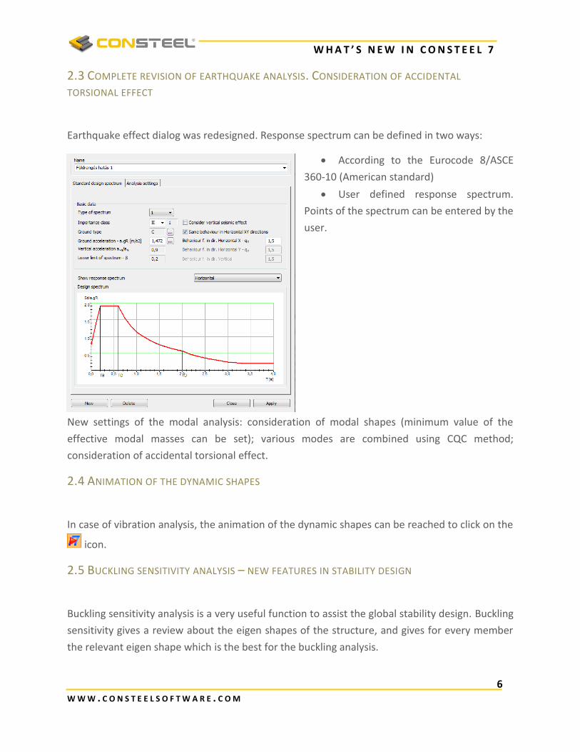
2.3 COMPLETE REVISION OF EARTHQUAKE ANALYSIS. CONSIDERATION OF ACCIDENTAL
TORSIONAL EFFECT
Earthquake effect dialog was redesigned. Response spectrum can be defined in two ways:
According to the Eurocode 8/ASCE
360-10 (American standard)
User defined response spectrum.
Points of the spectrum can be entered by the
user.
New settings of the modal analysis: consideration of modal shapes (minimum value of the
effective modal masses can be set); various modes are combined using CQC method;
consideration of accidental torsional effect.
2.4 ANIMATION OF THE DYNAMIC SHAPES
In case of vibration analysis, the animation of the dynamic shapes can be reached to click on the
icon.
2.5 BUCKLING SENSITIVITY ANALYSIS – NEW FEATURES IN STABILITY DESIGN
Buckling sensitivity analysis is a very useful function to assist the global stability design. Buckling
sensitivity gives a review about the eigen shapes of the structure, and gives for every member
the relevant eigen shape which is the best for the buckling analysis.

W H A T ’ S N E W I N C O N S T E E L 7
7 W W W . C O N S T E E L S O F T W A R E . C O M
As a new function, the upper limit of relevant buckling eigen values can be given.
3. STANDARD DESIGN
3.1 PARAMETERS OF THE EARTHQUAKE DESIGN ARE HANDLED BY THE EUROCODE NATIONAL
ANNEXES
Parameters of the EuroCode 8 can be review on the standard dialog in case of every national
annexes.

W H A T ’ S N E W I N C O N S T E E L 7
8 W W W . C O N S T E E L S O F T W A R E . C O M
3.2 NEW EUROCODE NATIONAL ANNEXES
Two more national annexes can be used to standard design:
Austrian national annex
Swedish national annex
3.3 NEW NATIONAL STANDARDS
Two more national standards can be used to standard design:
Spanish national standards: EAE and SE-AE.
The following features can reached according to the Spanish standards: automatic load
combinations and wind load generations; complete steel structure design
American national standards: ASCE 7-10 and AISC 360-10
The following features can reached according to the American standards: automatic
load combinations generation; earthquake effect; complete steel structure design

W H A T ’ S N E W I N C O N S T E E L 7
9 W W W . C O N S T E E L S O F T W A R E . C O M
4. DOCUMENTATION AND MODEL EXPORT
4.1 PICTURE MANAGER
New features on the picture manager dialog: preview of the saved pictures can be seen;
multiple selected pictures can be saved and deleted at the same time.
Screenshot can be printed directly from the create snapshot dialog.

W H A T ’ S N E W I N C O N S T E E L 7
1 0 W W W . C O N S T E E L S O F T W A R E . C O M
4.2 DOCUMENTATION TEMPLATE
Documentation templates can be saved. Most used documentation structures can be saved as
templates. Based on the templates, documentation can be created with one click.
4.3 EXPORT TO TEKLA STRUCTURES 18
Model export available to Tekla Structures 18. ConSteel supports only the 32bit versions.

W H A T ’ S N E W I N C O N S T E E L 7
1 1 W W W . C O N S T E E L S O F T W A R E . C O M
5. CSJOINT JOINT MODULE
5.1 BEAM SPLICEPLATE
Splice plate connection can be created and checked for same size beams. Number of the bolt
rows and columns can be changed. Plate on the flange could be on one side or both side.
W H A T ’ S N E W I N C O N S T E E L 7
1 2 W W W . C O N S T E E L S O F T W A R E . C O M
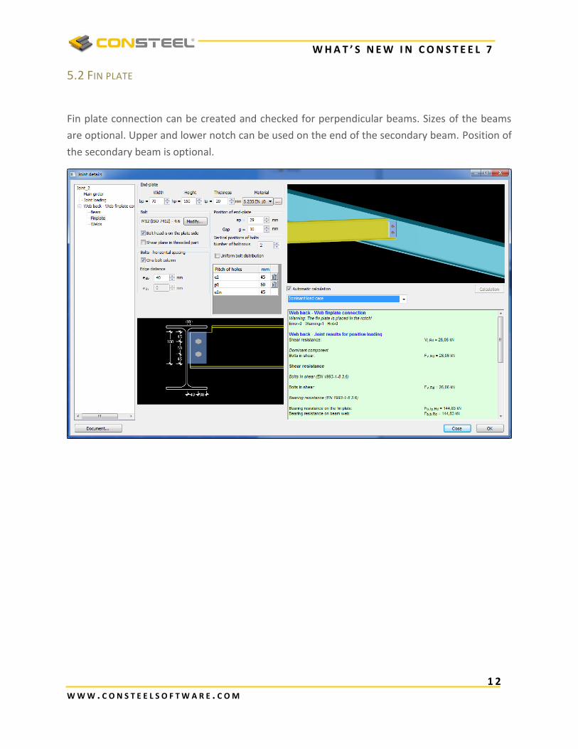
5.2 FIN PLATE
Fin plate connection can be created and checked for perpendicular beams. Sizes of the beams
are optional. Upper and lower notch can be used on the end of the secondary beam. Position of
the secondary beam is optional.

W H A T ’ S N E W I N C O N S T E E L 7
1 3 W W W . C O N S T E E L S O F T W A R E . C O M
5.3 HOLLOW SECTION MULTIPLANAR KK JOINT
Multiplanar KK joint can be created and checked. Angle between the two truss plane and the
angle of braces can be changed.

W H A T ’ S N E W I N C O N S T E E L 7
1 4 W W W . C O N S T E E L S O F T W A R E . C O M
5.4 SPLICE PLATE COMPONENT
Splice plate component can be created and checked.
4 types of components can be created:
one side, simple splice plate
one side, double splice plate
two side, double splice plate
two side, simple splice plate
Number of the bolt rows and columns can be changed. Moment resistance can be also checked.


