21
What’s with Scheduling? (Queues, Delays & Throughput) G. Mustafa © 11|21|2016
| Date post: | 14-Jan-2017 |
| Category: |
Documents |
| Upload: | ghulam-mustafa-ph-d |
| View: | 13 times |
| Download: | 0 times |
What’s with Scheduling? (Queues, Delays & Throughput)
G. Mustafa ©
11|21|2016

PART I : Erik’s Deli – Customer Flow

Erik’s Deli – The Lunch Scene
Erik’s Lunch Scene Erik’s lunch menu consists of cold cuts
and hot food. Customers, upon entrance
choose between cold or hot food, and
form queues, one for the cold, the other
for hot. In addition, each customer is
attributed with patience (low to high).
Those with low patience will leave the
queue, after a pre-assigned time and is
lost business. Customers wait in
respective queues to be served by
servers, attributed by service time –
some are slower. After customers are
served, they proceed to form a queue at
the cash register. The cashiers charge
them – these are also characterized by
their service time. Customers leave
Erik’s Deli with their food.
Erik plans to include a dinning area to
entice customers to stay longer and
hopefully order more food.
Co
ld F
oo
d H
ot Fo
od
Menu
Cashier
Customers Enter
Customers Exit
Customers Leaving
G. Mustafa©| 2016

Erik’s Deli Open for Lunch
Customers come in (exponentially distributed mean arrival time 1)
They randomly choose between cold and hot food (with 50% probability)
Customers are assigned serve time (exp. 5 mean)
They are handed menus (Assigned attributes)
Hostess routes them to cold or hot counters
Hot food queue
Cold cut queue
Hot Food servers
Cold Food servers
G. Mustafa©| 2016

Erik’s Deli Customer Flow Diagram
Customers Enter
Assigned Number
Handed Menu
Cold or Hot Cold Queue Hot Queue
Cold Counter Hot Counter
Cold Cus.
Served
Hot Cus.
Served
Checkout
Queue
Checkout
Cashier
G. Mustafa©| 2016

Erik’s Deli Customer Flow Model
Customers come in (exponentially distributed mean arrival time 1)
They randomly choose between cold and hot food (with 50% probability)
Customers are assigned serve time (exp. 5 mean)
They are handed menus (Assigned attributes)
Hostess routes them to cold or hot counters
Cold food queue
Hot food queue
Cold food queue length
Hot food queue length
Cold food serve counter
Hot Food counter
Cold food served
Cold food average wait
Hot Food served
Hot Food average wait
Served Customers
G. Mustafa©| 2016

Erik’s Deli Customer Flow Simulation
Cold Food Queue Hot Food Queue
Hot Food Wait Cold Food Wait
G. Mustafa©| 2016

Traffic on N85 @ Almedan Expressway (6-9am)
1
1
2
2
3
3
4
4
5
5
6
7
8
7
6
8
Average wait @ Almedan
Queue @ Almedan
G. Mustafa©| 2016

PART II : Cluster Tool Scheduling
G. Mustafa©| 2016

Input
Output
Process
Module A
Process
Module B
Wafer
Handling
Robot
Tool Architecture A wafer processing tool comprises
of two process modules. A single
wafer handling robot serves process
modules. Incoming wafers are
sorted and put in FOUPS of given
capacity. Once inside FOUPS, wafers
are transferred to process models A
or B. After the wafers are
processed, they are moved by the
Tool Architecture & Wafer Sequence
FOUP
A
FOUP
B
G. Mustafa©| 2016

Tool Architecture & Wafer Sequence
Wafer Process Sequence A wafer processing tool consists of two
process modules. Wafers, as they arrive,
are assigned a process A or B, and form
two queues, one for A, the other for B.
In addition, each wafer is attributed
with pre-process qualification metric
(process time etc). The wafers wait in
their respective queues (FOUPS) to be
served by process modules, that are
endowed with some process time with some
variability. After the wafers have been
processed, they proceed to form a queue
at the tool output. Wafers depart the
tool.
It has been determined that wafer handing
presents a major bottleneck. There are
plans to improve robot designs and motion
profiles. Tool architecture also needs
improvement (multiple process modules,
process time reduction, etc.) The
baseline architecture, as described,
needs to be evaluated for throughput to
prioritize design options.
Incoming wafers
FOUP A
Robot
Process
A Process
B
Outgoing wafers
Inspection
Queue
FOUP B
G. Mustafa©| 2016

Create discrete wafers
can be timed, random
or event based Assign attributes to wafers
They can be characteristics
Process time type, quality
Rout wafers
Based on attributes
Provide Process Modules
Define process characteristics
(constraints, timeouts, queue length)
System Model
process, wafer handling
Retire wafers
System Output
Bottlenecks
Efficiency
Utilization
Uptime
Downtime
Failure Rate
Statistics
Statistics Statistics
Statistics Statistics
System Optimization
Cluster Tool Discrete Event Model
G. Mustafa©| 2016

Cluster Tool Model
Incoming wafers FOUP
A
FOUP
B
Process
A
Process
B
Robot
Wafers come in at regular
Intervals, based on an
event Or randomly
Wafers are sorted based
on Attributes,
characteristics, process
Wafers are moved based
on motion profile or
robot characteristics
Wafers are processed
according to attributes.
Modules are assigned
process times, process
steps, etc.
G. Mustafa©| 2016
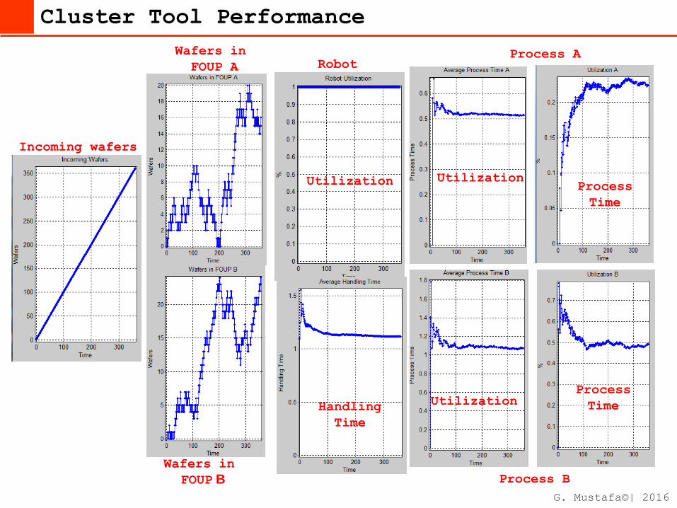
Cluster Tool Performance
Incoming wafers
Wafers in
FOUP B
Robot
Process B
Process A Wafers in
FOUP A
Utilization
Handling
Time
Utilization
Utilization Process
Time
Process
Time
G. Mustafa©| 2016

Wafer Sorter (2 POD)
A1 A2
B1 B2 R
A1 A2
B1 B2
R
Fast Robotics Slow Robotics
Wafer Sorting
Two type of wafers are to be sorted (A, B) and transported from input FOUPS
(A1, B2) to output FOUPS (A2, B2). Wafer handling is carried out by a wafer
handling robot that can move one wafer at a time from input to output. Sorting
is done according to FIFO. G. Mustafa©| 2016

PART II : Tool Design Optimization
G. Mustafa©| 2016

Throughput Improvement
Wafer Process Sequence A wafer processing tool consists of two
process modules. Wafers, as they arrive,
are assigned a process A or B, and form
two queues, one for A, the other for B.
In addition, each wafer is attributed
with pre-process qualification metric (low
to high). Those with low will leave the
queue. This amounts to productivity loss.
The wafers wait in their respective queues
to be served by process modules, that are
with some process time with some
variability – some are slower. After the
wafers have been processed, they proceed
to form a queue at the tool output for
inspection – these are also characterized
by their inspection time. Wafers depart
the tool.
There are plans to include a storage area
to improve wafer flow bottleneck; wafer
handling robots and process modules. The
baseline architecture, as described, needs
to be evaluated for throughput to
prioritize design options.
G. Mustafa©| 2016

PART III : Tool Architectures
G. Mustafa©| 2016

Sorters, Buffers and Clusters
G. Mustafa©| 2016

Cluster Tool Architectures
Robotics
G. Mustafa©| 2016

Cluster Tool Architectures
G. Mustafa©| 2016


![Whats Possible With Educational Technology With Notes2 Distributed [Autosaved]](https://static.documents.pub/doc/80x56/5462e6bab1af9f92238b51d9/whats-possible-with-educational-technology-with-notes2-distributed-autosaved.jpg)


