Wheel Truing Technology Development and Innovation Simmons Machine Tool Corporation David William Davis, President & COO Chris Johnson, Manufacturing Engineer Jason Steven Murphy, Marketing Specialist Brandon Teal, Product Manager, Wheel Truing/Reprofiling Wheel reprofiling machines have been in service since early in the history of railroading. During the steam era, the machines were initially configured in an above-floor installation, which required worn wheel sets be removed from a vehicle. Steam locomotives contained substantial moving parts that required a higher frequency of repair and maintenance while the wheel sets required less frequent service. As diesel locomotives became the primary source of motive power, a significant jump in productivity occurred in 1949, when the first pit-mounted, or underfloor, wheel truing machine was installed. Eliminating the time needed to remove the wheel set from a vehicle and then return it to the locomotive after reprofiling decreased the time required for the maintenance process. Since then, wheel truing machines have been installed in freight and transit maintenance facilities throughout North America. However, cycle times have remained largely the same since that first underfloor installation: approximately 40 minutes under normal wheel wear conditions. An underfloor wheel truing machine installation The railway industry has seen a revolution in the last decade in terms of leveraging new technologies to move products and people more efficiently, faster, and safer.
Transcript
Wheel Truing Technology Development and Innovation
Simmons Machine Tool Corporation David William Davis, President & COO Chris Johnson, Manufacturing Engineer
Jason Steven Murphy, Marketing Specialist Brandon Teal, Product Manager, Wheel Truing/Reprofiling
Wheel reprofiling machines have been in service since early in the history of railroading. During the steam era, the machines were initially configured in an above-floor installation, which required worn wheel sets be removed from a vehicle. Steam locomotives contained substantial moving parts that required a higher frequency of repair and maintenance while the wheel sets required less frequent service. As diesel locomotives became the primary source of motive power, a significant jump in productivity occurred in 1949, when the first pit-mounted, or underfloor, wheel truing machine was installed. Eliminating the time needed to remove the wheel set from a vehicle and then return it to the locomotive after reprofiling decreased the time required for the maintenance process. Since then, wheel truing machines have been installed in freight and transit maintenance facilities throughout North America. However, cycle times have remained largely the same since that first underfloor installation: approximately 40 minutes under normal wheel wear conditions.
An underfloor wheel truing machine installation
The railway industry has seen a revolution in the last decade in terms of leveraging new technologies to move products and people more efficiently, faster, and safer.
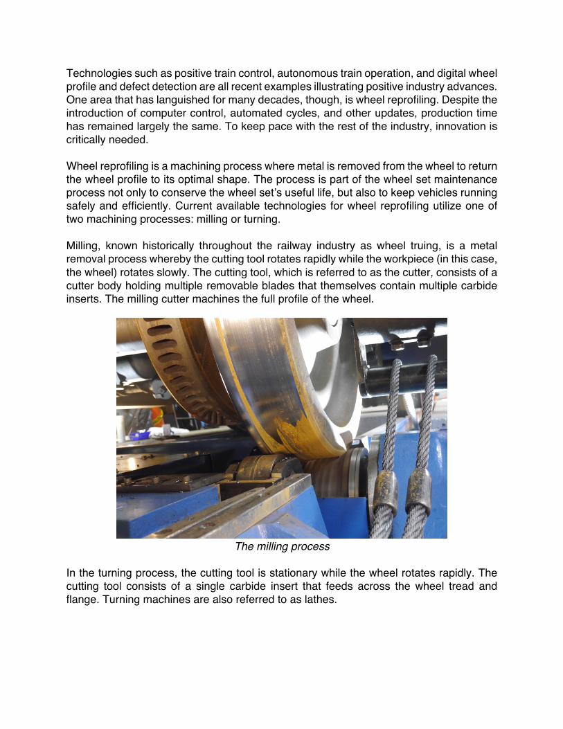
Technologies such as positive train control, autonomous train operation, and digital wheel profile and defect detection are all recent examples illustrating positive industry advances. One area that has languished for many decades, though, is wheel reprofiling. Despite the introduction of computer control, automated cycles, and other updates, production time has remained largely the same. To keep pace with the rest of the industry, innovation is critically needed. Wheel reprofiling is a machining process where metal is removed from the wheel to return the wheel profile to its optimal shape. The process is part of the wheel set maintenance process not only to conserve the wheel set’s useful life, but also to keep vehicles running safely and efficiently. Current available technologies for wheel reprofiling utilize one of two machining processes: milling or turning. Milling, known historically throughout the railway industry as wheel truing, is a metal removal process whereby the cutting tool rotates rapidly while the workpiece (in this case, the wheel) rotates slowly. The cutting tool, which is referred to as the cutter, consists of a cutter body holding multiple removable blades that themselves contain multiple carbide inserts. The milling cutter machines the full profile of the wheel.
The milling process
In the turning process, the cutting tool is stationary while the wheel rotates rapidly. The cutting tool consists of a single carbide insert that feeds across the wheel tread and flange. Turning machines are also referred to as lathes.
The turning process
This paper will focus on the development and innovations related to the milling process, and will demonstrate that milling offers more opportunities for productivity growth and other advantages. The paper will further discuss how the turning process has reached its maximum production capability. The only way to radically increase productivity is to rotate the wheel faster. Doing so amplifies the issues inherent in the turning process: the single point cutting tool cannot withstand machining wheel wear without risk of damage. Decreasing the feed rate allows for a safer process and a deeper depth of cut, but it produces longer “stringers” (which are difficult to control and process). It also increases cycle time, negating any productivity gains. The current proven way to increase productivity is to install more lathes running in tandem or larger groups, which requires a larger footprint for the system and substantially higher capital investment.
Turning limitations: feed rate versus depth of cut
Through extensive research and experience with both reprofiling processes, we propose that milling is the technology that has additional opportunity for cost effective innovations. The process is ideally suited for railway wheel set maintenance operations. The full-profile milling process manages wheel wear conditions with limited operator intervention. Milling permits machining through wheel defects such as flat spots and shelling without decreasing workpiece rotational speed or changing cutter feed rates. There’s also no need to undercut these wheel defects as required in the turning process, which means less service metal is removed. The slower rotational speed of the workpiece produces a more stable machining process by not inducing into the machining process dynamic forces caused by the large rotating mass of the wheel set. The milling process does not require substantive operator set-up and lends itself to considerable process automation. The chips created by the milling material removal process are small, facilitating simple containment and collection. The milling cutter was designed several decades ago and has not kept pace with innovations in the larger non-railway/general purpose machining industry. In the last eight years, advanced digital manufacturing techniques such as CAD/CAM (Computer Aided Design/Computer Aided Manufacturing) and 5-axis machining have been deployed to improve quality, performance, and cost. The wheel truing machine has historically relied on manual, external measurement tools to identify how much metal must be removed from the wheel. Measurement data from these tools can vary between operators based on simple human error. And while there have been some digital measurement tools introduced, they are still external to the machine.
Minimum Material Removed, StringersWasted Service Life, No Stringers
The current method by which the wheel set is held captive during the machining process, which is called clamping, is achieved by accessing the axle centers and applying significant pressure (6600 pounds / 3000 kg). This operation requires a large steel machine structure to withstand the forces generated between the machine’s centers (horizontal) and the machine’s cutters (vertical).
Wheel truing machine clamping process
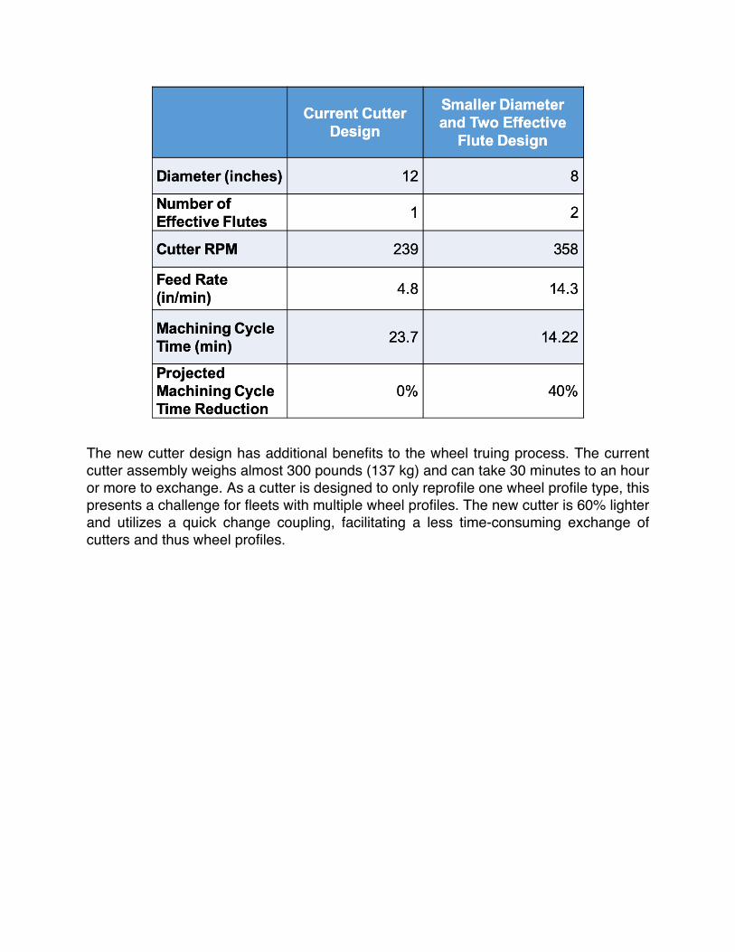
Currently, milling technology has only been applied to an underfloor machine configuration. While it is possible to process a range of vehicles or even loose wheel sets in this configuration, the most prevalent use is for reprofiling wheel sets of locomotives while on the vehicle. By deploying digital manufacturing techniques, a new milling cutter design has been developed with two effective flutes or double helix. The double helix design permits twice as much material removal per revolution, which allows for an increased feed rate. The outer diameter of the cutter has also decreased from 12 inches (305 mm) to 8 inches (203 mm). This change allows for an increased cutter RPM. When both of these design changes are implemented, the projected cycle time reduction is expected to be 40% (see attached table). A productivity increase of this amount would substantially reduce dwell or out of service time for locomotives with little additional capital investment.
The new cutter design has additional benefits to the wheel truing process. The current cutter assembly weighs almost 300 pounds (137 kg) and can take 30 minutes to an hour or more to exchange. As a cutter is designed to only reprofile one wheel profile type, this presents a challenge for fleets with multiple wheel profiles. The new cutter is 60% lighter and utilizes a quick change coupling, facilitating a less time-consuming exchange of cutters and thus wheel profiles.
Older milling cutter next to new smaller cutter
The new cutter design is further updated by placing the indexable carbide cutting inserts directly onto the cutter body as opposed to on removable blades. This change means less vibration is created throughout the tool during the machining process, creating a stiffer, stronger interface that extends the useable life of the inserts. The enhanced insert geometry as well as modern computer solid modeling lay-out tools also produce a more optimal wheel surface finish. While the modifications to the milling cutter design appear to be the most transformative, there are other developments taking place in the wheel truing machine’s design. One would be the wheel set clamping method. The current underfloor wheel lathe design offers the ability to reprofile a wheel set without accessing the axle centers. This operation requires the lathe to force the wheel set’s center line to be held at exactly the same place in space during the reprofiling process. This requires an immense amount of force, generally involving complex hydraulics and CNC systems, as well as a large machine structure to facilitate the operation. The new wheel truing milling machine design allows the wheel set center line to move while reprofiling. Instead of using heavy machine centers to clamp and hold the wheel set, a following probe monitors movement of the wheel set center line, and a closed loop servo system to keep the cutter at the correct radius. The axle centerline moves primarily vertically, but somewhat horizontally, as the wheel set rotates due to initial out-of-round condition, surface defects, a freshly cut surface contacting only one roller, etc. Our analysis shows that the horizontal movement has a negligible impact on the overall process. The newly integrated measurement system is used to find the initial location of axle center line with respect to cutter position. The cutter is then moved to the desired distance from axle centerline. If that centerline moves, the cutter moves with it,
maintaining a constant distance. The process is therefore centerless (not requiring machine to physically reference the axle centers) and completely independent of the condition (roundness) of the incoming wheels. Furthermore, this process will take an out of round wheel and ensure that it is trued round. Integrated measurement has also been introduced to the updated wheel truing machine design. As found throughout the railway industry, access to consistent and accurate measurement data has numerous benefits. The measurement data is collected pre-machining to influence a more precise reprofiling process. Parameters measured include wheel location (for cutter alignment), wheel diameter and width, the condition of the profile, flange height and width, wheel set back-to-back, and radial and axial runout. These parameters are also measured post-machining to confirm the wheel set has been trued to its target diameter. All of this data can be stored and evaluated later to better assess not just the state of the wheel truing machine, but also the state of the fleet’s wheel sets. This data would prove invaluable when looking to implement a preventive maintenance program.
Wheel measurement system
As mentioned earlier, wheel truing machines have historically been limited to underfloor installations. While the new wheel truing machine will continue to be available in that configuration, the milling technology is being applied to above-floor installations as well. Currently being tested is an above-floor wheel truing machine to maintain loose wheel sets, bogies, and locomotive combo units. The centerless design means a smaller and lighter machine which requires no pit.
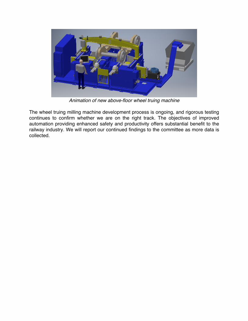
Animation of new above-floor wheel truing machine
The wheel truing milling machine development process is ongoing, and rigorous testing continues to confirm whether we are on the right track. The objectives of improved automation providing enhanced safety and productivity offers substantial benefit to the railway industry. We will report our continued findings to the committee as more data is collected.