16


IntroductionIntroduction
Products that don't performlike they should can be veryinconvenient, as depicted byour dedicated engineer on thecover. Although fixing the flattire is his immediate concern,avoiding the situation altogetherthrough improved productdesign is smarter. Our dedicatedengineer ponders the designand analysis considerations ofmodeling advanced productslike a tire, hoping to never bestuck without knowing whichway to go. Join our engineeron his journey as he searchesfor a fix for his tire problem,and discovers that F ≠ Ku istypically the rule, not theexception.
F = Ku
Analysis in structural ormechanical engineering meansthe application of an acceptableanalytical procedure based onengineering principles.Analysis is used to verify thestructural or thermal integrityof a design. Sometimes, thiscan be done using handbookformulas for simple structures.More often, however, thisanalysis is performed usingcomputers in order to predictproduct performance. The pre-dominant type of engineeringsoftware used in these analysesis based on the finite elementmethod, and this type ofanalysis is therefore calledfinite element analysis (FEA).
In the past 40 years, FEA hasbeen successfully applied in all
major industries, including:aerospace, automotive, energy, manufacturing, chemical, electronics, consumer, and medical industries. FEA is indeed oneof the major breakthroughs ofmodern engineering.
The origins of mechanics goback to early scientists such asIsaac Newton and RobertHooke. All freshmen physicsstudents learn Hooke's Law, asillustrated by simple spring,with stiffness K (N/m) loadedat the free end by a force F(N):
Hooke discovered a simple linear relationship betweenforce and deflection, F = Ku.
Thus, the deflection u can beeasily calculated by dividing Fby K, (This law is valid as longas the spring remains linearelastic, and the deflections aresuch that they do not causethe spring to yield or break.)If one applies twice the force,the spring will deflect twice asmuch. Simple - but not allproblems exhibit this simplebehavior, for example, ourdedicated engineer's tire.
FEA History
In the mid-fifties, Americanand British aeronautical engineers independently developed the finite elementmethod to analyze airplanestructures.
· Introduction 1
· How do I spot a nonlinear problem? 2
· When should I use nonlinear? 3
· What is the solution procedure? 4
· What are material nonlinearities? 5-6
· What are geometric nonlinearities? 7
· How do I model boundaries? - Contact! 8
· What about dynamics? 9
· What are the benefits of FEA? 10
· The world is full of nonlinear problems! 11-12
· What else does MSC.Software offer? 13
Let us take you on aNonlinear Journey
1

A structure can be idealized ascomposed of many small, discrete pieces called finiteelements. These engineersextended Hooke's basic ideainto large structures involvingthousands of simultaneousequations, and were able tosolve these equations using thefirst generation of computers.
Since linear FEA theory wasformulated first, these earlystructural analyses were linear.In the sixties, researchersstarted applying the finite element method to other fieldsin engineering science, such asfluid mechanics, heat transfer,electromagnetic wave propagation, and other fieldproblems. Applied mathematicians proved thatthe method converges to thecorrect results. Researchersalso started applying FEA tononlinear problems.
How to Spot a NonlinearProblem
Some everyday situations arenonlinear, and you probablydon't even recognize them:pressing your finger against aballoon to see a dimple; flexing a paper clip back andforth; crushing an aluminumcan so that it buckles; and hitting a pothole in the road.These cases all exhibit largedeformations, and sometimes,inelastic material behavior.
The three major types of nonlinearities are as follows:
· Material Nonlinearity(plasticity, creep, viscoelasticity)
· Geometric Nonlinearity(large deformations, largestrains, snap-through buckling)
· Boundary Nonlinearity(opening/closing of gaps, contact, follower force)
You can, of course, have combinations of any of these.To find evidence of possiblenonlinear behavior, look for:permanent deformations andany gross changes in geometry,cracks, necking, thinning, distortions in open sectionbeams, crippling, buckling,stress values which exceed theelastic limits of the materials,evidence of local yielding,shear bands, and temperaturesabove 30% of the melting temperature. In these cases,the stress is no longer proportional to the strain.
Typical force-displacementcurves are shown for linear(Hookean) and nonlinear material, as well as nonlinearstress-strain curve:
How about our Tire?
Tires are complex productsthat have high performancedemands. They must have adequate traction, and acceptable wear.
“How do I spot a nonlinear problem?”“How do I spot a nonlinear problem?”
Linear Force-Displacement
Nonlinear Force-Displacement
Nonlinear Stress-Strain
2
“When should I use nonlinear?”“When should I use nonlinear?”They should have low rollingresistance, for fuel economy.They must not debond ordelaminate. They should rollquietly. They should nothydroplane under wet conditions, and ultimately,they should not blowout or getflat, leaving you stranded inthe middle of the desert!
Effects due to friction, temperature and dynamics areimportant, which is why majortire manufacturers around theworld use nonlinear FEAcapabilities to improve tiredesigns, ride comfort and service life. A tire analysis caninvolve every type of nonlinearity.
To properly design a tire, arealistic model must be created, and designs optimized.The more designs you can turnaround and optimize in a virtual environment, the moreyou will save on costly physicalprototyping and testing. Sowhat's involved? Let's look atnonlinear problems in generalfirst.
Nonlinear FEA Concepts
You should recognize at theoutset that nonlinear problemsare inherently more complexto analyze than linear problems. And, the "principleof superposition" (which statesthat the resultant deflection,stress, or strain in a systemdue to several forces is thealgebraic sum of their effectswhen separately applied) no longer applies.
Finite element analysis is anapproximate analysis methodwhich is only as accurate as:
· the quality of the model· the material properties used
(and their assumptions)· representation of the loads
and boundary conditions· the solution algorithm.
The analyst's experience andjudgement therefore becomecritical to the success of a nonlinear analysis because ofthe decisions that must bemade. In nonlinear FEA, thefollowing relationships (whichare assumed to be linear in linear FEA) may be violated:
1. The strain is no longersmall.
Most metallic materials are nolonger useful when the strainexceeds one or two percent.However, some materials,notably rubbers, elastomers,and plastics, can be strained tohundreds of a percent and willtherefore require finite (large)strain analysis.
2. The strain-displacementrelationship is no longer linear.
This is true if the rotationsbecome large even though thestrains are still small. Thechanges in the deformed shapecan no longer be ignored. Thephysics of buckling, rubberanalysis, metal forming, amongothers, requires that either aquadratic relationship exitsbetween the strain and displacement (Green-Strain) ora logarithmic relationshipexists. Engineering stress is nolonger appropriate because ofgeometric changes and the truestress or Cauchy stress shouldbe used.
3

3. The stress-strain law maybecome nonlinear.
Even within the useful stressrange of the material. Thisbehavior is typical of mostmetals, rubbers and elastomers, and certain composite materials whoseproperties are unequal in tension and compression.
4. The original equilibriumequations (relating stress toloads) may have to be updated.
Due to the geometricalchanges in the shape of thestructure. These relationsmean that, in nonlinear FEA,the load is no longer proportional to the displacement, that is, F≠Ku.
Incremental SolutionProcedures
FEA is an approximate technique, and there existmany methods to solve thebasic equations. In nonlinearFEA, two popular incrementalequilibrium equations are: fullNewton-Raphson and modifiedNewton-Raphson.
The full Newton-Raphson (N-R)method assembles and solvesthe stiffness matrix every iteration. It has quadratic convergence properties, whichmeans in subsequent iterationsthe relative error decreasesquadratically. It gives goodresults for most nonlinearproblems.
In addition, other solution procedures offered in nonlinearFEA codes include:· Modified Newton Raphson· Strain Correction Method· Secant Method· Direct Substitution Method· Quasi-Newton Methods
“What is the solution procedure?”“What is the solution procedure?”
4

When stresses go beyond thelinear elastic range, materialbehavior can be broadlydivided into two classes:
· Time-independent behavior(plasticity-applicable to mostductile metals; nonlinear elasticity-applicable to rubber,elastomers)
· Time-dependent behavior (creep, viscoplasticity-applicableto high-temperature applications, concrete; viscoelasticity-applicable toelastomers, glass, plastics).
Here we'll give you a briefintroduction to these concepts(many of which are quite complex and are the subjectsof textbooks). An elastic-plastic material may bedefined as a material, which,upon reaching a certain stressstate, undergoes deformation,which is irreversible. Thisresults in a behavior, which ispath-dependent. A basicassumption in elastic-plasticanalysis is that deformationcan be divided into an elasticpart and in an elastic (plastic)part.
Yield Conditions
The yield stress is a measuredvalue that separates the elastic and inelastic behaviorof a material. Its magnitude isusually obtained from a uniaxialtest. However, stresses in astructure are multiaxial, and ameasure of yielding in a multiaxial state of stress is
called the "yield condition" or"yield criterion."
The most widely used yieldcondition is the Von Mises,which states that yieldingoccurs when effective (orequivalent) stress equals theyield stress as measured in auniaxial test. This yield condition agrees fairly wellwith the observed behavior ofductile metals such as low-carbon steels and aluminum.
Another yield condition is theTresca, which states that yielding occurs when the maximum shear stress reachesthe value it has when yieldingoccurs in the tensile test.
A third yield condition is theDrucker-Prager (or Mohr-Coulomb), which is based on ayield surface that exhibitshydrostatic stress dependence.Such behavior is observed inmaterials such as certain soils,rock-like materials, and ice.
Many advanced yield criteriahave been formulated eitherfor specific materials orobserved phenomena.
This includes Gurson model fordamage, Shima for powdermaterials, and Cam-Clay forsoils to name but a few.
Work Hardening Rules
In a uniaxial test, the workhardening slope is defined asthe slope of the stress-plasticstrain curve. It relates theincremental stress to incremental plastic strain inthe inelastic region and dictates the conditions of subsequent yielding.
The isotropic hardening ruleassumes that the center of theyield surface remains stationary in the stress space,but the size (radius) of theyield surface expands due tostrain hardening. It is considered suitable for problems in which the plasticstraining far exceeds the incipient yield state. It istherefore widely used for manufacturing processes andlarge-motion dynamic problems.The kinematic-hardening ruleassumes that the Von Misesyield surface does not changein size or shape, but the center of the yield surfaceshifts in stress space.
“What are material nonlinearities?”“What are material nonlinearities?”
5

Straining in one directionreduces the yield stress in theopposite direction. It is used incases where it is important tomodel the Bauschinger effect.
Creep
Creep is continued deformationunder constant load, and is atype of time-dependent inelasticbehavior, which can occur atany stress level. It is an important consideration for elevated-temperature stressanalysis (e.g., in nuclear reactors) and in materials suchas concrete. Creep behaviorcan be characterized in threestages: primary, secondary, andtertiary.
Creep is generally representedby a Maxwell model, whichconsists of a spring and a viscous dashpot in series.For materials that undergocreep, with the passing of timethe load decrease for a constantdeformation. This phenomenonis termed relaxation.
Viscoelasticity andViscoplasticity
Viscoelasticity, as its nameimplies, is a generalization ofelasticity and viscosity. It isoften represented by a Kelvinmodel, which assumes a springand dashpot in parallel.Examples of viscoelastic materials are glass and plastics.
A viscoplastic material exhibitsthe effects of both creep andplasticity, and can be represented by a creep(Maxwell) model modified toinclude a plastic element.
Such a material behaves like aviscous fluid when it is in theplastic state.
Tire Material Modeling
Tires can use the generalized Mooney, Ogden, Arruda-Boyceand Gent models, or you can define your own model throughuser-routines.
Rubber and Elastomers
An elastomer is a natural orsynthetic polymeric materialwith rubberlike properties ofhigh extensibility and flexibility.Elastomers show nonlinearelastic stress-strain behavior,which means that uponunloading the stress-straincurve is retraced and there isno permanent deformation.
6

Rubber and elastomers arenearly incompressible, whichmeans zero volumetric changeunder load and a Poisson's ratioof nearly equal to one-half.This incompressibility constraint means that FEAcodes can handle these typesof materials only if they have certain special element formulations (for instance,"Herrmann elements" or"mixed/hybrid formulations").FEA codes with this nonlinear elastic capabilitygenerally offer one or morehyper-elastic material models(strain energy functions), suchas the two-constant Mooney-Rivlin model, one-constantNeo-Hookean model, and thefive-constant, third-orderJames-Green-Simpson model.Material constant for thesemodels are obtained fromexperimental data.
Large Deformations
In implicit analysis, using theNewton Raphson procedure,the relationship betweenincremental load ∆F and displacement ∆u is called atangent stiffness KT.
This stiffness has three components: the material stiffness, the initial stress stiffness, and the geometricstiffness. The material stiffnessmay be the same elastic stiffnessas that used in linear FEA.
The second term representsthe resistance to load causedby realigning the current internalstresses when displacementsoccur. The third term representsthe additional stiffness due tothe nonlinear strain-displacementrelationship.
In solving this type of problem,the load is increased in smallincrements, the incrementaldisplacement ∆u is found andthe next value of the tangentstiffness is found, and so on.There are three approachesavailable to solve these typesof problems:
· Total Lagrangian methodwhich refers everything to theoriginal undeformed geometry,and is applicable to problemsexhibiting large deflectionsand large rotations (but withsmall strains), such as thermalstress, creep, and civil engineering structures. It isalso used in rubber analysiswhere large elastic strains arepossible.
· Updated Lagrangian methodwhere the mesh coordinatesare updated after each increment, and is applied toproblems featuring largeinelastic strains such as metalforming.
· Eulerian methodwhere the mesh is fixed inspace and the material flowsthrough the mesh, and is suitable for steady-state problems such as extrusion andfluid mechanics problems.
Tire Deformations
“What are geometric nonlinearities?”“What are geometric nonlinearities?”
Tires can be modeled using a large strain viscoelasticity modelwith damage effects, such as the Mullins and Miehe models.
7
Contact, by nature, is a nonlinear boundary value problem. During contact,mechanical loads and perhapsheat are transmitted acrossthe area of contact. If frictionis present, shear forces arealso transmitted. Contact canbe achieved in various ways.One way is in MSC.Marc. InMSC.Marc, areas of potentialcontact do not need to beknown prior to the analysis. Ifthe code used interface elements instead, you wouldhave to know where all contact will occur in advance.
Both deformable-to-rigid anddeformable-to-deformablecontact situations are allowedin MSC.Marc. You need only toidentify bodies which arepotential candidates for contactduring the analysis. Self-contact,common in rubber problems, isalso permitted. The bodies canbe either rigid or deformable,and the algorithm tracks variable contact conditionsautomatically. Rigid surfacesmay be directly imported from aCAD system, and their exactmathematical form is used inthe calculations. For adeformable body, the geometryis normally represented by theedges of the element, butMSC.Marc can improve upon thisby fitting a curve or surfacethrough the boundary. Thisimproves the accuracy of thesolution by representing thegeometry better than the discrete finite elements. This isimportant for concentric shaftsor rolling simulation.
Using MSC.Marc, you no longerneed to worry about the location and open/close statuschecks of “gap elements,” orabout “master-slave” relationships. Also, coupledthermo-mechanical contactproblems (for example, rolling,casting, extrusion, car tire)and dynamic contact problems can be treated.
Friction
MSC.Marc offers two classicalfriction models: Coulomb friction and shear friction. Inaddition, a user subroutine isavailable in MSC.Marc, permitting you to constantlymonitor the interface conditionsand modify the friction effect if necessary.
In this way, friction can bemade to vary arbitrarily- as afunction of location, pressure,temperature, amount of sliding,and other variables. In order toreduce numerical instabilities inthe transition between stickingand slipping, a regularizationprocedure is applied.
Sometimes, the physics of deformation dictates modelingthe regions of sticking fairlyaccurately (for example, driverpulley transferring torquethrough the belt to a driven pulley). For such cases, a stick-slip friction model basedon Coulomb is also available.Because friction generates heat,a coupled thermo-mechanicalanalysis is often required in rubber contact problems.
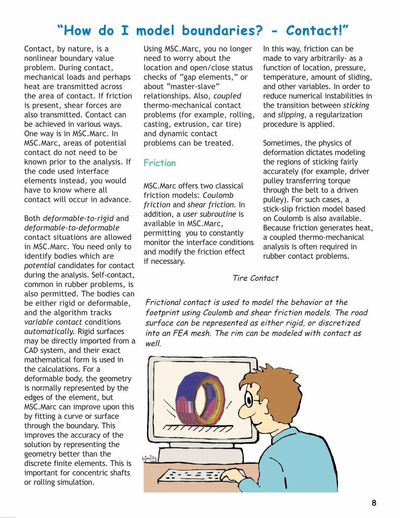
Frictional contact is used to model the behavior at the footprint using Coulomb and shear friction models. The roadsurface can be represented as either rigid, or discretizedinto an FEA mesh. The rim can be modeled with contact aswell.
Tire Contact
“How do I model boundaries? - Contact!”“How do I model boundaries? - Contact!”
8

Nonlinear DynamicAnalysis
An important FEA application isin the area of nonlineardynamics, for example, in pipewhip, impact, and other intermittent contact problems.To solve the matrix equationsof motion numerically, mostcodes offer either implicitdirection integration schemesor explicit schemes.
Implicit
An implicit operator solves amatrix system, one or moretimes per step, to advance thesolution. It is appealing for alinear transient problem,because it allows a larger time
step and has almost no numerical stability problems.Treatment of boundary nonlinearities must occur within a step, and this factalong with the solution of largesystems of equations make thecoding more complicated thanan explicit one.Examples of implicit operatorsinclude: Newmark-beta (themost popular), Wilson-theta,Hilber-Hughes-Taylor, andHoubolt. Some of these operators have been shown byresearchers to exhibit numerical damping problems,sensitivity to time step size, orstability problems, and theuser must be extremely carefulin their use.
Explicit
An explicit operator advancesa solution without forming astiffness matrix, a fact thatmakes the coding much simpler. An example of anexplicit scheme is the centraldifference operator, which isconditionally stable. For agiven time step size, an explicit formulation requiresfewer computations per timestep than an implicit one.Complicated boundary conditions are handled easily,because nonlinearities are handled after a step has beentaken. The disadvantage of anexplicit method is the existenceof a definite stability limit,which means very small timesteps are required and often,higher computer costs areincurred.
Implicit vs Explicit
The choice of whether to useimplicit or explicit time integrationv schemes is verysubtle and depends on: thenature of the dynamic problem; the type of finiteelements which make up themodel; the size of the model;and the velocities of the problem compared to thespeed of sound in the material.
“What about dynamics?”“What about dynamics?”
Tire Dynamics
Noise due to sidewall vibrations and standing waves require acoupled structural acoustics transient analysis. FEA can handle this as well as thermo-mechanical coupling of eithersteady state or transient analyses.
9

Virtual Manufacturing
Virtual Manufacturing involvesthe use of a computer to simulate a product and theprocesses involved in its fabrication. Simulation technology enables companiesto optimize key factors directly affecting the profitability of their manufactured products. Theseinclude manufacturability, finalshape, residual stress levels,and product durability.Profitability is improved byreducing costs of production,material usage, and warrantyliabilities.
At the core of VirtualManufacturing lies nonlinearFEA technology. The technologyhas enabled companies to simulate fabrication and testing in a more realisticmanner than ever before.
Virtual Manufacturing reducesthe cost of tooling, eliminatesthe need for multiple physicalprototypes, resulting inreduced material waste.Because you can "get it rightthe first time" it provides manufacturers with the confidence of knowing thatthey can deliver quality products to market on timeand within budget.
From a business perspective, itis clear. Small improvements inmanufacturing have dramaticand profound effects in termsof cost and quality.
Return on Investment calculations have shown thatsmall savings in material usagedeliver enormous returns in a manufacturing environment.For example, an automotivecustomer found that eachounce of material saved in aforged car engine componentsaves many hundreds of thousands of dollars of material costs each year. Calculations are simple thanksto the large manufacturingruns, however the same customer went on to calculatethe impact on customer satisfaction from the extrapower available to the engineand reduced running costs ofthe final vehicle.
Nonlinear FEA allows you tosimulate the behavior of yourproduct and based on theinformation obtained from thesimulation, apply engineeringjudgment to optimize thedesign. To summarize, some ofthe advantages of thisenhanced design processachieved:· Improved performance and
quality of finished product
· Verification of designs before prototyping
· Elimination of costly manufacturing iterations
· Reduced material waste
· Reduced time-to-market
· Competitive advantage over Competitors
Improving YourCompetitive Advantage
The design of products typically is carried out in atrial and error fashion, relyingheavily on manufacturing experience, as well as costlyshop floor trials. A viable alternative for reducing thesedesign costs and increasingyour competitiveness is theuse of Virtual Manufacturing.
The primary benefit of Virtual Manufacturing isreduced product developmentand manufacturing costs,achieved by improved designs.Using computer simulation,designers can quickly eliminatefaulty designs and optimize thedesign before manufacture.
While such Virtual Prototypingtechniques and processes arestill evolving, it is by no meansmerely a concept or theoreticalconstruct; it is already a dawning reality and is fullyimplemented in the form ofMSC.Marc, MSC.SuperForm,MSC.SuperForge, andMSC.Dytran.
“What are the benefits of FEA?”“What are the benefits of FEA?”
10

Disc Brake
Head GasketBiomedical Stents
Isolation Bearing
Our enlightened engineer clearly sees many problems requiring nonlinear solutions.
11

Biomedical Stent
Stents are used at various locations throughout thehuman body, but some of themost intensive work involvescoronary arteries, where stentsare used to maintain the opening in the vessels supplying blood directly to theheart muscle.
"Biomedical applications represent some of the mostdemanding of all work done inFEA. Projects often requiremodeling of systems consistingof multiple components withnonlinear materials, complex3D geometries and surface-to- surface contacts as well ascoupled conditions that mayinvolve simultaneous mechanicalthermal, electromagnetic loading and fluid-structureinteraction." (Dr. SvennBorgersen, BIOSMulations Inc.,Eagan, MN)
Biomedical applications havehigh safety requirements andthus require extensive nonlinearanalyses.
Head Gasket
The manufacture of an enginegasket includes a number ofnonlinearities. A FEA simulationof tightening the head boltsdeforms the gasket's headaround the cylinders into theplastic range. The simulationlets you visualize the deformation of the head anddetermine how well the seal is made.
This analysis improved the gasket’s wear, performance,and warranty costs.
Disc Brake
A nonlinear FEA simulationdetermines the temperaturedistribution with time as thebrake pads are applied to the disc. A contour plot oftemperature on the discdisplays the peak temperaturesand lets you verify the disc's performance.
Isolation Bearing
Seismic Isolation Bearings areused for earthquake protectionof structures. They are composed of an elastomericcompound layered betweenthin steel shims. Nonlinear\FEA verifies the bearingsaxial and shear stiffness, aswell as the internal stresses in the material under earthquake loading.
These are just a few of the many opportunities youwill find to use nonlinearFEA. Remember, “Nature
is Nonlinear.”
“The world is full of nonlinear problems!”“The world is full of nonlinear problems!”
12

MSC.Software
MSC.Software is the worldleader in nonlinear and coupled physics simulation.Our technology has evolvedand matured through constantdevelopment and worldwideuse by thousands of engineers.Our manufacturing tools havehelped users save hundreds ofmillions of dollars since inception, and to this day, continue to catapult profitsand slash manufacturing costs.To find out how MSC.Software'smany capabilities will enableyou to solve your most difficultengineering challenges, contact us online at www.mscsoftware.com or bytelephone at (800) 642-7437ext. 2500.
MSC.visualNastranEnterprise
MSC.visualNastran Enterpriseproducts are built for professional analysts and engineers who need directaccess to the full power ofMSC.Software's simulationtechnology. The family includesMSC.Nastran, MSC.Patran,MSC.Marc, MSC.Dytran,MSC.Mvision and MSC.Fatigue,as well as MSC.Software’srenowned industry specificapplications. This software ishighly functional and is able tobe integrated with a widerange of other enterprise software including CAD, PDM,test software and other CAE software.
MSC.Marc
MSC.Marc is an advanced finiteelement system focused onnonlinear design and analysisas well as the process modeling community. In addition to a unique ability tosolve very large problems inparallel using the domaindecomposition technique,MSC.Marc is known for greatdepth in solution procedures,material models, and elementtechnology. Whether yourdesign is of steel, rubber, plastic, glass, or concrete,MSC.Marc can be used to solvethe problem.
MSC.SuperForm
MSC.Marc SuperForm is a comprehensive manufacturingprocess simulation programbased on the MSC.Marc technology. It is used by engineering analysts to simulate a wide variety offorming operations, includingforging, bending, extrusion,rolling and cogging.
MSC.Dytran
MSC.Dytran is an advancedfinite element program capableof simulating many commonforming processes, includingthe forming of complex sheetmetal parts such as automobilehood, fenders, and side panels,as well as forming of householdand industrial containers likeplastic bottles.
MSC.SuperForge
MSC.SuperForge is a Windowsbased application customdeveloped for forging processsimulation. Its object orientedprocess modeling, forgingprocess terminology, and"meshless" technology make itan ideal simulation tool forforging process design engineersand shop floor technicians.
MSC.visualNastranDesktop
MSC.visualNastran Desktopproducts have been developedto support the many designengineers at large or smallcompanies who need to verifythe functionality of theirdesign concepts without extensive simulation support.This family includes the popu-lar CAD integrated versions ofMSC.visualNastran 4D, theleading PC based motion simulation package. Programmanagement as well asMarketing professionals willbenefit from sophisticated simulation work through theuse of MSC.visualNastranStudio. Highly advanced visualization and animationcapabilities provide the insight required to makedesign intuitive.
“What else does MSC.Software offer?”“What else does MSC.Software offer?”
13

14
“Thanks MSC.Software!”“Thanks MSC.Software!”
Brochure produced by Marlene Hoctor and Ludi Billings

MSC.Software provides the industry's most comprehensivesupport system with over 50 offices worldwide to providelocal and centralized support. Investing in MSC.Softwaregives you access to extensive client support through comprehensive documentation, direct technical expertise,and customized training classes.
To find your local MSC.Software office or tolearn more about our company and our prod-ucts, please contact:
Corporate:MSC.Software Corporation2 MacArthur PlaceSanta Ana, California 92707 USA
1 714 540.8900Fax: 1 714 784.4056
Information Center:1 800 642.7437 ext. 2500 (U.S. only)1 978 453.5310 ext. 2500 (International)
Worldwide Web - www.mscsoftware.comOn-line Purchases - www.engineering-e.comOn-line Simulation - www.simulationcenter.com
Europe:MSC.Software GmbHAm Moosfeld 1381829 Munich, Germany
49 89 43 19 87 0Fax: 49 89 43 61 71 6
Asia-Pacific:MSC Japan Ltd.Entsuji-Gadelius Bldg.2-39,Akasaka 5-chomeMinato-ku, Tokyo 107-0052 Japan
81 3 3505 0266Fax: 81 3 3505 0914
MSC, Marc and Patran are registered trademarks of MSC.Software Corporation. Nastran is a registeredtrademark of NASA. MSC.visualNastran, MSC.Nastran, MSC.Patran, MSC.Dytran, MSC.Marc,MSC.SuperForm, MSC.SuperForge, MSC.Fatigue, and MSC.Mvision are trademarks of MSC.SoftwareCorporation All other trademarks are the property of their registered owners. All specifications are subjectto change without notice.
©2001 MSC.Software Corporation


