94
® Where Tradition and In- novation Meet Eagle Folding Camping Trailer Owner’s Manual
| Date post: | 13-Mar-2018 |
| Category: |
Documents |
| Upload: | dangkhuong |
| View: | 217 times |
| Download: | 2 times |

®
Where Tradition and In-novation Meet
EagleFolding Camping
TrailerOwner’s Manual

© 1997 Jayco, Inc. LITHO U.S.A. 01-2 PART NO. 0152076
This manual has been provided by Jayco, Inc. for the solepurpose of providing instructions concerning the operation andmaintenance of this vehicle and its components. Nothing in thismanual creates any warranty, either expressed or implied. The onlywarranty offered by Jayco, Inc. is as set forth in the limited warrantyapplicable to this vehicle.
The owner’s failure to provide required service and/ormaintenance could result in the loss of warranty. The owner shouldreview Jayco’s limited warranty and the limited warranties of allother manufacturers offering them that are applicable to this vehicle.
Instructions are included in the manual for operating variouscomponents which are optional on some vehicles. In addition, theowner should refer to individual manufacturer’s operating instructionscontained in the owner’s packet.
CAUTION: Read all instructions prior to using camper.
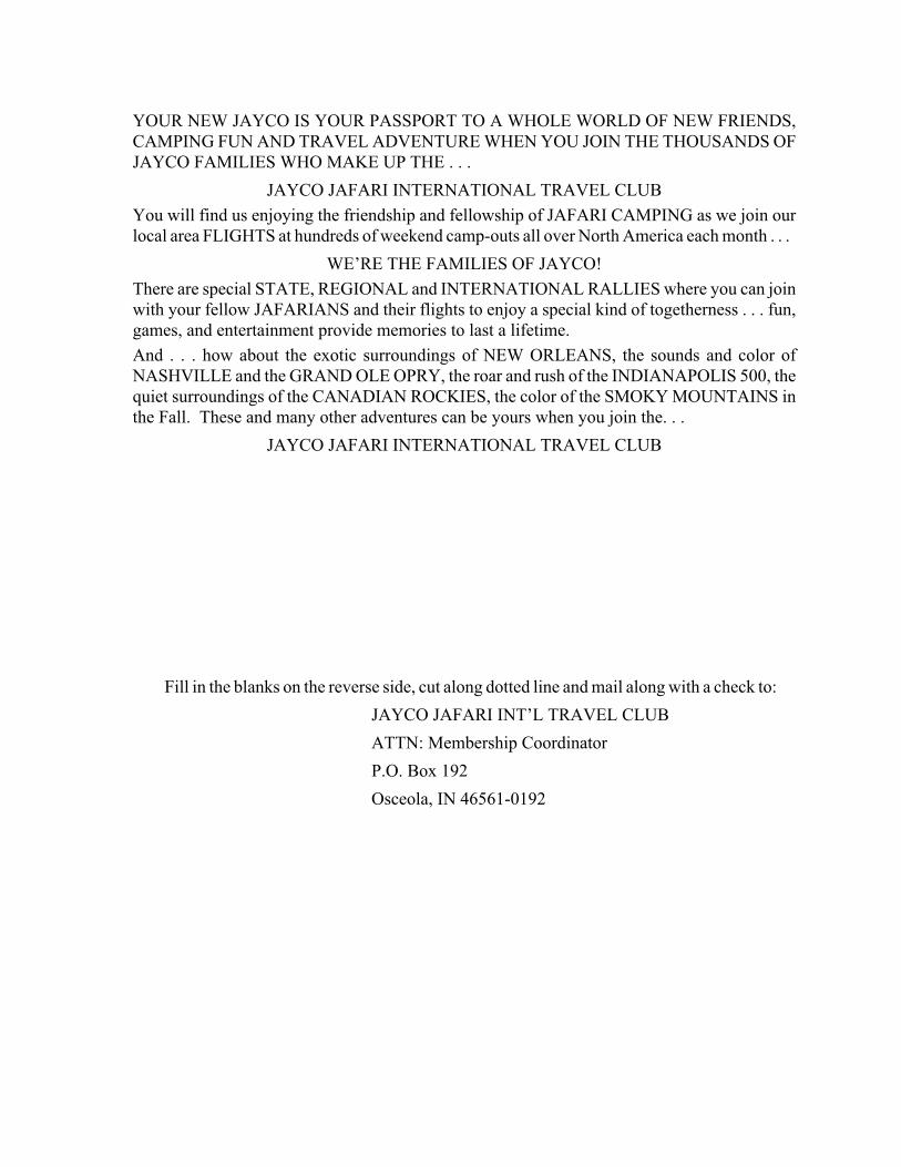
YOUR NEW JAYCO IS YOUR PASSPORT TO A WHOLE WORLD OF NEW FRIENDS,CAMPING FUN AND TRAVEL ADVENTURE WHEN YOU JOIN THE THOUSANDS OFJAYCO FAMILIES WHO MAKE UP THE . . .
JAYCO JAFARI INTERNATIONAL TRAVEL CLUB
You will find us enjoying the friendship and fellowship of JAFARI CAMPING as we join ourlocal area FLIGHTS at hundreds of weekend camp-outs all over North America each month . . .
WE’RE THE FAMILIES OF JAYCO!
There are special STATE, REGIONAL and INTERNATIONAL RALLIES where you can joinwith your fellow JAFARIANS and their flights to enjoy a special kind of togetherness . . . fun,games, and entertainment provide memories to last a lifetime.
And . . . how about the exotic surroundings of NEW ORLEANS, the sounds and color ofNASHVILLE and the GRAND OLE OPRY, the roar and rush of the INDIANAPOLIS 500, thequiet surroundings of the CANADIAN ROCKIES, the color of the SMOKY MOUNTAINS inthe Fall. These and many other adventures can be yours when you join the. . .
JAYCO JAFARI INTERNATIONAL TRAVEL CLUB
Fill in the blanks on the reverse side, cut along dotted line and mail along with a check to:
JAYCO JAFARI INT’L TRAVEL CLUB
ATTN: Membership Coordinator
P.O. Box 192
Osceola, IN 46561-0192

Yes, it’s for everyone with a JAYCO RV; young couples just starting out, families spending quality timetogether, the young at heart expanding their life experiences. Whether you belong to another campingclub, have always traveled alone, or are just starting, don’t miss out on one of the most priceless benefitsof being an RV family . . . meet new friends and spend a bit of your camping life with some of the finestpeople you will ever have the opportunity to share a campfire or treasure a moment of golden living witha . . FIFTH-WHEEL TRAVEL TRAILER. . .SPORT UTILITY TRAILER . . . CONVENTIONALTRAVEL TRAILER . . . TYPE C MOTORHOME . . . FOLDING CAMPING TRAILER . . . it doesn’tmatter. If you are a JAYCO RV FAMILY, then you are eligible to become a Jayco Jafari Member.
YOU WILL NEVER BE SORRY YOU MADE THE DECISION!
Your membership entitles you to:• Special international decals for your unit.• The Hitch newsletter with schedules of upcoming events and activities.• A membership roster - containing the names and addresses of current members of the club will
be sent bi-yearly.• Discount Cards for several national theme parks including Six Flags and Busch Corp. Parks.• A special price is available on Wheeler’s Campground Guides.• Discounts with Hertz Rental Car.• Discounts with Coach Net, an emergency roadside service.• Farm & City Insurance has RV insurance available at discounted rates to current Jayco Jafari
International Club members.• All of this, plus the joy of meeting new friends and enjoy Jafari adventures around the country.
Start with the first phase of your camping life...just complete the following application and forward it tothe Jayco Jafari International Travel Club office. Your membership application may also be completedonline, by visiting our website at www.jaycorvclub.com. If you have further questions, contact the cluboffice direct at the website or by calling 800-262-5178. Localcalls can be made to 574-258-0571.
WELCOME TO THE JAFARI FAMILY!
TO: Membership Coordinator for the Jayco Jafari International Travel Club
Please enroll us as members in the Jayco Travel Club. We are ready to roll to where the “friends we justhaven’t met yet” have the coffee on the fire and are waiting for us to arrive: We are ...
Name: Spouse:
Address: Phone:
City: State: Zip:
Email:
Ages of Children at Home:
Our JAYCO is a: Our Dealer(type & size)
Membership Dues:One year $25.00 Amount enclosed. $Two years: $45.00 Check #:Three years: $65.00
(signature) (date)
�
i
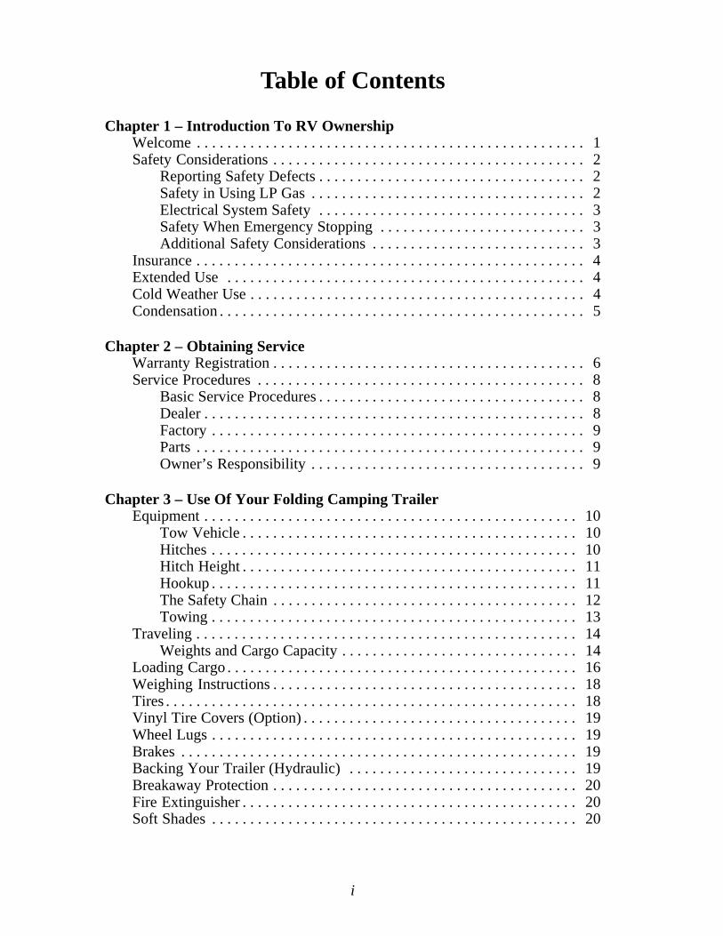
Table of Contents
Chapter 1 – Introduction To RV OwnershipWelcome . . . . . . . . . . . . . . . . . . . . . . . . . . . . . . . . . . . . . . . . . . . . . . . . . . . 1Safety Considerations . . . . . . . . . . . . . . . . . . . . . . . . . . . . . . . . . . . . . . . . . 2
Reporting Safety Defects . . . . . . . . . . . . . . . . . . . . . . . . . . . . . . . . . . . 2Safety in Using LP Gas . . . . . . . . . . . . . . . . . . . . . . . . . . . . . . . . . . . . 2Electrical System Safety . . . . . . . . . . . . . . . . . . . . . . . . . . . . . . . . . . . 3Safety When Emergency Stopping . . . . . . . . . . . . . . . . . . . . . . . . . . . 3Additional Safety Considerations . . . . . . . . . . . . . . . . . . . . . . . . . . . . 3
Insurance . . . . . . . . . . . . . . . . . . . . . . . . . . . . . . . . . . . . . . . . . . . . . . . . . . . 4Extended Use . . . . . . . . . . . . . . . . . . . . . . . . . . . . . . . . . . . . . . . . . . . . . . . 4Cold Weather Use . . . . . . . . . . . . . . . . . . . . . . . . . . . . . . . . . . . . . . . . . . . . 4Condensation . . . . . . . . . . . . . . . . . . . . . . . . . . . . . . . . . . . . . . . . . . . . . . . . 5
Chapter 2 – Obtaining ServiceWarranty Registration . . . . . . . . . . . . . . . . . . . . . . . . . . . . . . . . . . . . . . . . . 6Service Procedures . . . . . . . . . . . . . . . . . . . . . . . . . . . . . . . . . . . . . . . . . . . 8
Basic Service Procedures . . . . . . . . . . . . . . . . . . . . . . . . . . . . . . . . . . . 8Dealer . . . . . . . . . . . . . . . . . . . . . . . . . . . . . . . . . . . . . . . . . . . . . . . . . . 8Factory . . . . . . . . . . . . . . . . . . . . . . . . . . . . . . . . . . . . . . . . . . . . . . . . . 9Parts . . . . . . . . . . . . . . . . . . . . . . . . . . . . . . . . . . . . . . . . . . . . . . . . . . . 9Owner’s Responsibility . . . . . . . . . . . . . . . . . . . . . . . . . . . . . . . . . . . . 9
Chapter 3 – Use Of Your Folding Camping TrailerEquipment . . . . . . . . . . . . . . . . . . . . . . . . . . . . . . . . . . . . . . . . . . . . . . . . . 10
Tow Vehicle . . . . . . . . . . . . . . . . . . . . . . . . . . . . . . . . . . . . . . . . . . . . 10Hitches . . . . . . . . . . . . . . . . . . . . . . . . . . . . . . . . . . . . . . . . . . . . . . . . 10Hitch Height . . . . . . . . . . . . . . . . . . . . . . . . . . . . . . . . . . . . . . . . . . . . 11Hookup . . . . . . . . . . . . . . . . . . . . . . . . . . . . . . . . . . . . . . . . . . . . . . . . 11The Safety Chain . . . . . . . . . . . . . . . . . . . . . . . . . . . . . . . . . . . . . . . . 12Towing . . . . . . . . . . . . . . . . . . . . . . . . . . . . . . . . . . . . . . . . . . . . . . . . 13
Traveling . . . . . . . . . . . . . . . . . . . . . . . . . . . . . . . . . . . . . . . . . . . . . . . . . . 14Weights and Cargo Capacity . . . . . . . . . . . . . . . . . . . . . . . . . . . . . . . 14
Loading Cargo . . . . . . . . . . . . . . . . . . . . . . . . . . . . . . . . . . . . . . . . . . . . . . 16Weighing Instructions . . . . . . . . . . . . . . . . . . . . . . . . . . . . . . . . . . . . . . . . 18Tires . . . . . . . . . . . . . . . . . . . . . . . . . . . . . . . . . . . . . . . . . . . . . . . . . . . . . . 18Vinyl Tire Covers (Option) . . . . . . . . . . . . . . . . . . . . . . . . . . . . . . . . . . . . 19Wheel Lugs . . . . . . . . . . . . . . . . . . . . . . . . . . . . . . . . . . . . . . . . . . . . . . . . 19Brakes . . . . . . . . . . . . . . . . . . . . . . . . . . . . . . . . . . . . . . . . . . . . . . . . . . . . 19Backing Your Trailer (Hydraulic) . . . . . . . . . . . . . . . . . . . . . . . . . . . . . . 19Breakaway Protection . . . . . . . . . . . . . . . . . . . . . . . . . . . . . . . . . . . . . . . . 20Fire Extinguisher . . . . . . . . . . . . . . . . . . . . . . . . . . . . . . . . . . . . . . . . . . . . 20Soft Shades . . . . . . . . . . . . . . . . . . . . . . . . . . . . . . . . . . . . . . . . . . . . . . . . 20

ii
Setting Up Your Camping Trailer . . . . . . . . . . . . . . . . . . . . . . . . . . . . . . . 21Opening Your Camper . . . . . . . . . . . . . . . . . . . . . . . . . . . . . . . . . . . . 21
For models with slideout . . . . . . . . . . . . . . . . . . . . . . . . . . . . . . 22To Install Door . . . . . . . . . . . . . . . . . . . . . . . . . . . . . . . . . . . . . . 22For Inside/Outside Galley (Model 12MK only) . . . . . . . . . . . . . 24
Closing Camper for Travel . . . . . . . . . . . . . . . . . . . . . . . . . . . . . . . . 25Canopy Setup . . . . . . . . . . . . . . . . . . . . . . . . . . . . . . . . . . . . . . . . . . . . . . 27Screen Room Setup . . . . . . . . . . . . . . . . . . . . . . . . . . . . . . . . . . . . . . . . . . 28
Chapter 4 – The SystemsPlumbing System. . . . . . . . . . . . . . . . . . . . . . . . . . . . . . . . . . . . . . . . . . . . 29
Fresh Water . . . . . . . . . . . . . . . . . . . . . . . . . . . . . . . . . . . . . . . . . . . . 29Water Pressure Regulator . . . . . . . . . . . . . . . . . . . . . . . . . . . . . . 30Optional Outside Shower . . . . . . . . . . . . . . . . . . . . . . . . . . . . . . 30Sanitizing Potable Water Systems . . . . . . . . . . . . . . . . . . . . . . . 30Drainage - Fresh Water . . . . . . . . . . . . . . . . . . . . . . . . . . . . . . . . 30Drainage - Waste Water . . . . . . . . . . . . . . . . . . . . . . . . . . . . . . . 31Gray Water Holding Tank - option . . . . . . . . . . . . . . . . . . . . . . . 31
Cassette Toilet (Option) . . . . . . . . . . . . . . . . . . . . . . . . . . . . . . . . . . . 32Shower System (Option on Some Models) . . . . . . . . . . . . . . . . . . . . 34Winterizing Camping Trailer . . . . . . . . . . . . . . . . . . . . . . . . . . . . . . . 34
Non-Power Supply Systems . . . . . . . . . . . . . . . . . . . . . . . . . . . . 34Demand or Power Plumbing Systems . . . . . . . . . . . . . . . . . . . . 34Drain Traps . . . . . . . . . . . . . . . . . . . . . . . . . . . . . . . . . . . . . . . . . 35Optional Thetford Cassette Toilet . . . . . . . . . . . . . . . . . . . . . . . 35
Electrical System . . . . . . . . . . . . . . . . . . . . . . . . . . . . . . . . . . . . . . . . . . . . 36Changes, Modifications and Additions . . . . . . . . . . . . . . . . . . . . . . . 36120-Volt AC System . . . . . . . . . . . . . . . . . . . . . . . . . . . . . . . . . . . . . 36GFCI . . . . . . . . . . . . . . . . . . . . . . . . . . . . . . . . . . . . . . . . . . . . . . . . . . 37Testing Instructions GFCI . . . . . . . . . . . . . . . . . . . . . . . . . . . . . . . . . 37Air Conditioner (Option) . . . . . . . . . . . . . . . . . . . . . . . . . . . . . . . . . . 3812-Volt DC System . . . . . . . . . . . . . . . . . . . . . . . . . . . . . . . . . . . . . . 39
Converter . . . . . . . . . . . . . . . . . . . . . . . . . . . . . . . . . . . . . . . . . . 39Interior . . . . . . . . . . . . . . . . . . . . . . . . . . . . . . . . . . . . . . . . . . . . . . . . 39Batteries (Option) . . . . . . . . . . . . . . . . . . . . . . . . . . . . . . . . . . . . . . . 39Battery Charger . . . . . . . . . . . . . . . . . . . . . . . . . . . . . . . . . . . . . . . . . 40Trailer Hitch Plug . . . . . . . . . . . . . . . . . . . . . . . . . . . . . . . . . . . . . . . 40Fuse and Bulb Chart . . . . . . . . . . . . . . . . . . . . . . . . . . . . . . . . . . . . . 41
LP Fuel System . . . . . . . . . . . . . . . . . . . . . . . . . . . . . . . . . . . . . . . . . . . . . 41LP Container . . . . . . . . . . . . . . . . . . . . . . . . . . . . . . . . . . . . . . . . . . . 41Servicing and Filling LP Containers . . . . . . . . . . . . . . . . . . . . . . . . . 42Installing LP Containers . . . . . . . . . . . . . . . . . . . . . . . . . . . . . . . . . . 43OPD Overfill Protection . . . . . . . . . . . . . . . . . . . . . . . . . . . . . . . . . . 44
Single Cylinder Mounted on A-Frame . . . . . . . . . . . . . . . . . . . . 44Double Cylinder Mounted on A-Frame . . . . . . . . . . . . . . . . . . . 44
Main Supply Hose . . . . . . . . . . . . . . . . . . . . . . . . . . . . . . . . . . . . . . . 45Regulator . . . . . . . . . . . . . . . . . . . . . . . . . . . . . . . . . . . . . . . . . . . . . . 45
iii
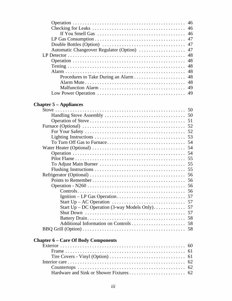
Operation . . . . . . . . . . . . . . . . . . . . . . . . . . . . . . . . . . . . . . . . . . . . . . 46Checking for Leaks . . . . . . . . . . . . . . . . . . . . . . . . . . . . . . . . . . . . . . 46
If You Smell Gas . . . . . . . . . . . . . . . . . . . . . . . . . . . . . . . . . . . . 46LP Gas Consumption . . . . . . . . . . . . . . . . . . . . . . . . . . . . . . . . . . . . . 47Double Bottles (Option) . . . . . . . . . . . . . . . . . . . . . . . . . . . . . . . . . . 47Automatic Changeover Regulator (Option) . . . . . . . . . . . . . . . . . . . 47
LP Detector . . . . . . . . . . . . . . . . . . . . . . . . . . . . . . . . . . . . . . . . . . . . . . . . 48Operation . . . . . . . . . . . . . . . . . . . . . . . . . . . . . . . . . . . . . . . . . . . . . . 48Testing . . . . . . . . . . . . . . . . . . . . . . . . . . . . . . . . . . . . . . . . . . . . . . . . 48Alarm . . . . . . . . . . . . . . . . . . . . . . . . . . . . . . . . . . . . . . . . . . . . . . . . . 48
Procedures to Take During an Alarm . . . . . . . . . . . . . . . . . . . . . 48Alarm Mute . . . . . . . . . . . . . . . . . . . . . . . . . . . . . . . . . . . . . . . . . 48Malfunction Alarm . . . . . . . . . . . . . . . . . . . . . . . . . . . . . . . . . . . 49
Low Power Operation . . . . . . . . . . . . . . . . . . . . . . . . . . . . . . . . . . . . 49
Chapter 5 – AppliancesStove . . . . . . . . . . . . . . . . . . . . . . . . . . . . . . . . . . . . . . . . . . . . . . . . . . . . . 50
Handling Stove Assembly . . . . . . . . . . . . . . . . . . . . . . . . . . . . . . . . . 50Operation of Stove . . . . . . . . . . . . . . . . . . . . . . . . . . . . . . . . . . . . . . . 51
Furnace (Optional) . . . . . . . . . . . . . . . . . . . . . . . . . . . . . . . . . . . . . . . . . . 52For Your Safety . . . . . . . . . . . . . . . . . . . . . . . . . . . . . . . . . . . . . . . . . 52Lighting Instructions . . . . . . . . . . . . . . . . . . . . . . . . . . . . . . . . . . . . . 53To Turn Off Gas to Furnace . . . . . . . . . . . . . . . . . . . . . . . . . . . . . . . . 54
Water Heater (Optional) . . . . . . . . . . . . . . . . . . . . . . . . . . . . . . . . . . . . . . 54Operation . . . . . . . . . . . . . . . . . . . . . . . . . . . . . . . . . . . . . . . . . . . . . . 54Pilot Flame . . . . . . . . . . . . . . . . . . . . . . . . . . . . . . . . . . . . . . . . . . . . . 55To Adjust Main Burner . . . . . . . . . . . . . . . . . . . . . . . . . . . . . . . . . . . 55Flushing Instructions . . . . . . . . . . . . . . . . . . . . . . . . . . . . . . . . . . . . . 55
Refrigerator (Optional) . . . . . . . . . . . . . . . . . . . . . . . . . . . . . . . . . . . . . . . 56Points to Remember . . . . . . . . . . . . . . . . . . . . . . . . . . . . . . . . . . . . . . 56Operation - N260 . . . . . . . . . . . . . . . . . . . . . . . . . . . . . . . . . . . . . . . . 56
Controls . . . . . . . . . . . . . . . . . . . . . . . . . . . . . . . . . . . . . . . . . . . . 56Ignition – LP Gas Operation . . . . . . . . . . . . . . . . . . . . . . . . . . . . 57Start Up – AC Operation . . . . . . . . . . . . . . . . . . . . . . . . . . . . . . 57Start Up – DC Operation (3-way Models Only) . . . . . . . . . . . . . 57Shut Down . . . . . . . . . . . . . . . . . . . . . . . . . . . . . . . . . . . . . . . . . 57Battery Drain . . . . . . . . . . . . . . . . . . . . . . . . . . . . . . . . . . . . . . . . 58Additional Information on Controls . . . . . . . . . . . . . . . . . . . . . . 58
BBQ Grill (Option) . . . . . . . . . . . . . . . . . . . . . . . . . . . . . . . . . . . . . . . . . . 58
Chapter 6 – Care Of Body ComponentsExterior . . . . . . . . . . . . . . . . . . . . . . . . . . . . . . . . . . . . . . . . . . . . . . . . . . . 60
Frame . . . . . . . . . . . . . . . . . . . . . . . . . . . . . . . . . . . . . . . . . . . . . . . . . 61Tire Covers - Vinyl (Option) . . . . . . . . . . . . . . . . . . . . . . . . . . . . . . . 61
Interior care . . . . . . . . . . . . . . . . . . . . . . . . . . . . . . . . . . . . . . . . . . . . . . . . 62Countertops . . . . . . . . . . . . . . . . . . . . . . . . . . . . . . . . . . . . . . . . . . . . 62Hardware and Sink or Shower Fixtures . . . . . . . . . . . . . . . . . . . . . . . 62

iv
Paneling . . . . . . . . . . . . . . . . . . . . . . . . . . . . . . . . . . . . . . . . . . . . . . . . . . . 62Floor . . . . . . . . . . . . . . . . . . . . . . . . . . . . . . . . . . . . . . . . . . . . . . . . . . . . . 62Fabric Components . . . . . . . . . . . . . . . . . . . . . . . . . . . . . . . . . . . . . . . . . . 63
Definitions . . . . . . . . . . . . . . . . . . . . . . . . . . . . . . . . . . . . . . . . . . . . . 63Interior . . . . . . . . . . . . . . . . . . . . . . . . . . . . . . . . . . . . . . . . . . . . 63Exterior . . . . . . . . . . . . . . . . . . . . . . . . . . . . . . . . . . . . . . . . . . . . 63
Fabric Care . . . . . . . . . . . . . . . . . . . . . . . . . . . . . . . . . . . . . . . . . . . . . . . . 64Cushions/Bed Mats . . . . . . . . . . . . . . . . . . . . . . . . . . . . . . . . . . . . . . 64SoftShades™ . . . . . . . . . . . . . . . . . . . . . . . . . . . . . . . . . . . . . . . . . . . 64NapSak™ . . . . . . . . . . . . . . . . . . . . . . . . . . . . . . . . . . . . . . . . . . . . . . 64Tents . . . . . . . . . . . . . . . . . . . . . . . . . . . . . . . . . . . . . . . . . . . . . . . . . . 64Exterior . . . . . . . . . . . . . . . . . . . . . . . . . . . . . . . . . . . . . . . . . . . . . . . 64Interior . . . . . . . . . . . . . . . . . . . . . . . . . . . . . . . . . . . . . . . . . . . . . . . . 65Canopy . . . . . . . . . . . . . . . . . . . . . . . . . . . . . . . . . . . . . . . . . . . . . . . . 66
Chapter 7 – Maintenance/StorageChanging The Tire . . . . . . . . . . . . . . . . . . . . . . . . . . . . . . . . . . . . . . . . . . 68Brake Maintenance & Lubrication . . . . . . . . . . . . . . . . . . . . . . . . . . . . . . 69LP Gas Bottles . . . . . . . . . . . . . . . . . . . . . . . . . . . . . . . . . . . . . . . . . . . . . . 69Storage . . . . . . . . . . . . . . . . . . . . . . . . . . . . . . . . . . . . . . . . . . . . . . . . . . . . 70Maintenance Chart . . . . . . . . . . . . . . . . . . . . . . . . . . . . . . . . . . . . . . . . . . 71Maintenance Checklist . . . . . . . . . . . . . . . . . . . . . . . . . . . . . . . . . . . . . . . 76Extended Transferable Limited Warranty . . . . . . . . . . . . . . . . . . . . . . . . . 79Towable Transferable Limited Warranty . . . . . . . . . . . . . . . . . . . . . . . . . 81Limited Warranty Transfer Application . . . . . . . . . . . . . . . . . . . . . . . . . . 83

1
CHAPTER 1INTRODUCTION TO RV OWNERSHIP
WELCOMEThank you for purchasing your Jayco Recreational Vehicle and welcome to the world ofrecreational vehicle travel. Your purchase of a Jayco RV allows you to enter this uniqueworld of camping and leisure in a grand style. Your Jayco RV has been designed andengineered to offer you many comforts of home that will make your campingexperience as enjoyable as possible. Jayco recreational vehicles are designed, con-structed and intended to be used as temporary living quarters for recreational,camping and travel uses, all as defined in the bylaws of the Recreation VehicleIndustry Association. Our recreational vehicles are not intended for the hauling ofcargo.
This owner’s manual was prepared to assist you in understanding the proper use andoperation of various containment systems, servicing and maintenance of componentparts, and explanation of your warranty protection. If you are a newcomer to RV travel,you will especially appreciate the suggestions and “shop talk” information to be foundthroughout this manual to help you obtain the most pleasure from the use of yourvehicle.
The information in this manual reflects the most current available to us at the time ofpublication. If you find the components in your recreational vehicle vary significantlyfrom what is described in this manual, please disregard that section and follow theinstructions provided by that particular component manufacturer. You should carefullyread and understand this owner’s manual which is a supplement to various otherinstructions supplied by the manufacturers of separately warranted products.
Keep this owner’s manual in your recreational vehicle for handy reference. Get to knowyour new vehicle and how it operates. You should carefully read and understand theseinstructions and information supplied by manufacturers of separately warranted products,since they contain important operating, safety, and maintenance instructions. If you havequestions that are not adequately answered by this manual or other booklets, consult yourdealer. If he cannot satisfactorily answer your questions, he will call our staff or referyou to us for help.
Every effort has been made to provide you with a safe, dependable product. Your vehiclecomplies with applicable requirements of Federal Motor Vehicle Safety Standards, StateRegulations, Canadian Standards Associations (CSA) where applicable, and complieswith requirements of ANSI Standard A119.2, the nationally recognized “Standard ForRecreational Vehicles – Installation of Plumbing, Heating and Electrical Systems.” TheRecreational Vehicle Industry Association (RVIA) and Canadian Standards Association(CSA) periodically inspect our production line and assist us in maintaining strict compli-ance with installation and safety standards for those systems. Your follow-up withperiodic safety inspections and a program of preventive maintenance is importantfor the continuation of safe and trouble-free operation.
Camping is a great way to relax and enjoy the outdoors with your friends and family.Please remember to tread lightly on our beautiful land and leave only your footprints sothat others may enjoy nature as much as you did.
The Jayco FamilyJayco, Inc.
2
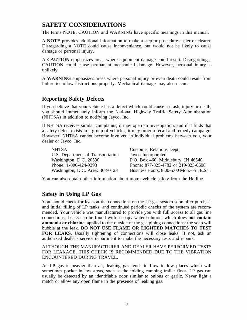
SAFETY CONSIDERATIONSThe terms NOTE, CAUTION and WARNING have specific meanings in this manual.
A NOTE provides additional information to make a step or procedure easier or clearer.Disregarding a NOTE could cause inconvenience, but would not be likely to causedamage or personal injury.
A CAUTION emphasizes areas where equipment damage could result. Disregarding aCAUTION could cause permanent mechanical damage. However, personal injury isunlikely.
A WARNING emphasizes areas where personal injury or even death could result fromfailure to follow instructions properly. Mechanical damage may also occur.
Reporting Safety DefectsIf you believe that your vehicle has a defect which could cause a crash, injury or death,you should immediately inform the National Highway Traffic Safety Administration(NHTSA) in addition to notifying Jayco, Inc.
If NHTSA receives similar complaints, it may open an investigation, and if it finds thata safety defect exists in a group of vehicles, it may order a recall and remedy campaign.However, NHTSA cannot become involved in individual problems between you, yourdealer or Jayco, Inc.
NHTSA Customer Relations Dept.U.S. Department of Transportation Jayco IncorporatedWashington, D.C. 20590 P.O. Box 460, Middlebury, IN 46540Phone: 1-800-424-9393 Phone: 877-825-4782 or 219-825-0608Washington, D.C. Area: 368-0123 Business Hours: 8:00-5:00 Mon.–Fri. E.S.T.
You can also obtain other information about motor vehicle safety from the Hotline.
Safety in Using LP GasYou should check for leaks at the connections on the LP gas system soon after purchaseand initial filling of LP tanks, and continued periodic checks of the system are recom-mended. Your vehicle was manufactured to provide you with full access to all gas lineconnections. Leaks can be found with a soapy water solution, which does not containammonia or chlorine, applied to the outside of the gas piping connections: the soap willbubble at the leak. DO NOT USE FLAME OR LIGHTED MATCHES TO TESTFOR LEAKS. Usually tightening of connections will close leaks. If not, ask anauthorized dealer’s service department to make the necessary tests and repairs.
ALTHOUGH THE MANUFACTURER AND DEALER HAVE PERFORMED TESTSFOR LEAKAGE, THIS CHECK IS RECOMMENDED DUE TO THE VIBRATIONENCOUNTERED DURING TRAVEL.
As LP gas is heavier than air, leaking gas tends to flow to low places which willsometimes pocket in low areas, such as the folding camping trailer floor. LP gas canusually be detected by an identifiable odor similar to onions or garlic. Never light amatch or allow any open flame in the presence of leaking gas.

3
It is very important to have the LP gas turned off during refueling of tow vehicles. Somestates prohibit gas appliances to be operated during travel, especially in undergroundtunnels.
Never allow gas containers to be filled above the liquid capacity indicated on thecontainer. If a container is overfilled, liquid gas may flow through the regulator causingit to freeze and/or introduce a dangerous excessive gas pressure into the lines. Inaddition, an overfilled container placed in hot sunlight may expel excess gas through therelief valve and be susceptible to ignition by any nearby open flame.
Electrical System SafetyCircuit breakers and fuses are installed to protect electrical circuits from overloading. Donot make unauthorized changes to circuitry or add on fixed appliances yourself. If youwish to make changes, consult your dealer and he will assist you in obtaining a safeinstallation.
An approved power supply cord has been supplied with the vehicle. Always use this cordfor hook-up to the 120-volt source. Note that the cord has a three pin plug, whichprovides proper grounding through the third (round) pin. Grounding is your personalprotection from electrical shock.
WARNING: Do not use an adapter, cheater, or extension cord that will breakthe continuity of the grounding circuit connected to the third pin. NEVERremove the grounding pin to connect a non-grounded, two-prong receptacle.Any deviation from this will potentially cause a fire from overheating.
Safety When Emergency StoppingPull off the roadway as far as possible for emergency situations and turn on the vehicularhazard warning flashers. If necessary, display your road flags and/or reflective triangularhighway warning devices.
NOTE: Always carry road flags and/or reflective triangular highway warning devicesto be displayed when necessary.
Additional Safety Considerations
WARNING: For traveling safety, it is extremely important to read andunderstand the towing, hitching and loading cargo information provided inChapter 3. If you do not understand the information provided, please consultyour dealer or Jayco owner representative.
• Sanitize the fresh water supply system periodically (see sanitizing instructions).• Prevent water connection fittings from coming in contact with the ground or drain hose
to reduce chance of contamination.• Enlist services of a qualified or certified RV technician to repair and maintain gas or
electrical appliances.• Carefully read the loading section under Chapter 3 related to your respective trailer.

4
• Ensure that tires are in good condition and properly inflated. Proper inflation should bemonitored closely. Neglecting to do so could result in overheating of a tire, which couldresult in a blowout.
• Check and tighten wheel lugs after the first 10 miles, 25 miles and then again after 50miles. Check periodically thereafter.
• Check brakes in a safe area - not while traveling a busy highway.• Always block trailer wheels solidly before unhitching.• Before leaving a camp area with a trailer in tow, insure that the safety pin or locking
lever is seated, breakaway wire is attached to tow vehicle, the jack is raised so that itcannot touch the ground, the dolly wheel removed, 120-volt electrical cord properlystored, safety chains are connected, and all interior lights are off.
• Observe the warning labels attached to your vehicle concerning LP gas, water, electricityand loading.
• Observe the maintenance chart in Chapter 7 related to your respective unit.
INSURANCEAs with your automobile, it is important that you protect yourself and others withinsurance coverages for personal liability, theft, collision, property damage, etc. Yourdealer will assist you in obtaining appropriate insurance for your protection or you maycheck with the company which provides your automobile insurance.
EXTENDED USEThis folding camping trailer has been built for enjoyment in a recreational manner. It isnot intended to be used as full-time living quarters.
CAUTION: Continuous living in your folding camping trailer could cause accel-erated wear and damage to components.
COLD WEATHER USEFolding camping trailers have no provisions for cold weather use.
• Winter use is NOT recommended due to the inability to adequately insulate the tentfabric.
• Proper care should be taken with the fresh water and draining systems to avoid freez-ing problems. Consult your local dealer or RV supply house for additional material.
• Adequate gas and electrical supply is needed along with protection from possible freeze-ups on the gas regulator.
• During cold weather usage, ventilation or the addition of a dehumidifier may be requiredto reduce condensation. Reference “Condensation.”
5
CONDENSATIONCondensation is a natural phenomenon. The amount of condensation will vary with theclimate conditions, particularly the relative humidity. Condensation occurs because thereis water vapor present in the air, which each of us adds by breathing, bathing andcooking. The water vapor collects where there is available air space, and when thetemperature reaches the ‘dew point’ the water vapor in the air condenses and changes toliquid form. Most people have experienced a similar phenomenon when moisture formson kitchen windows and bathroom mirrors during cool weather.
Proper ventilation and, if needed, the use of a dehumidifier will assist in controlling thecondensation. Many RV and marine dealers carry small dehumidifiers especially sizedfor recreation use. Condensation causes dampness, mildew, staining and if allowed tocontinue at high levels, damage to the tent, paneling and wood structures.
6
CHAPTER 2OBTAINING SERVICE
WARRANTY REGISTRATION

7
8
SERVICE PROCEDURES
Basic Service ProceduresWe are interested in your satisfaction. Only by having your complete confidence andsatisfaction with our product and its service can we assure our continued success asmanufacturers of recreation vehicles. We have found that continuing a pleasant andeffective relationship through our dealers is equally as important as maintaining thetechnical excellence of our product. Your authorized dealer will cordially assist you inproviding service maintenance, selection of options and instructions concerning theoperation of your vehicle.
Should you have a problem with service, please follow these instructions in sequence.
1. Contact your selling dealer’s service department for an appointment. Describe to thebest of your knowledge the nature of the problem.
2. Contact the owner or General Manager of the dealership should the initial attemptfail with the service department.
3. If further assistance is needed contact:Customer Relations Dept.Jayco IncorporatedP.O. Box 460Middlebury, IN 46540Phone: 877-825-4782 or 219-825-0608Business Hours: Monday – Friday 8:00 – 5:00 EST
Give all the above information as requested along with the serial number of the unit inquestion and we will make every attempt to resolve your problem.
Please bear in mind that most problems arise from misunderstandings concerningwarranty coverage and service. In most instances, you will be referred to the dealer leveland problems will be resolved with the dealer’s facilities and personnel.
DealerYour authorized Jayco dealer has inspected and serviced your new Jayco RV. He isauthorized to service and maintain your folding camping trailer as needed. All warrantyrepairs are to be performed by the selling dealer unless Jayco gives prior approval.
Some RV dealers may be authorized service centers for certain manufacturers ofproducts warranted separately. Check with your dealer before contacting others to reducedelays. If your Jayco dealer is not an authorized service center for the product inquestion, he can assist you in obtaining authorized service.

9
FactoryA factory service department is operated at our Middlebury, Indiana, manufacturingfacility. Should your Jayco RV be in need of repairs and your dealer recommends thatthe factory make the necessary repairs, it may be returned to our plant upon followingthese procedures:
A. You or your dealer must make an appointment prior to returning it to the factoryservice department.
B. All transportation costs are the responsibility of the owner. You may need toarrange for alternative accommodations for some types of repairs. Please be pre-pared accordingly.
PartsParts are available at most Jayco dealerships or your dealer can order parts for you asneeded. Should you be unable to find a dealer in your local area, contact our CustomerService Department at 877-825-4782 or 219-825-0608. We will assist you in providingparts through an authorized dealer or from Jay Parr Supply, our parts department locatedin Middlebury, Indiana.
Owner’s ResponsibilityAs a new owner of a Jayco recreation vehicle, you are responsible for regular andproper maintenance. This will help you prevent conditions arising from neglect thatare not covered by your Jayco Limited Warranty.
Maintenance service should be performed in accordance with this owner’s manual andany other applicable manuals.
As the owner, it is your responsibility and obligation to return the RV to an authorizeddealer for repairs and service. Reference your Limited Warranty for additional informa-tion. Because the authorized dealer where you purchased your RV is responsible for itsservicing before delivery and has an interest in your continued satisfaction, we recom-mend that inspection, warranty and maintenance services be performed by the dealership.
If you are traveling and are unable to locate an authorized Jayco dealer, or an authorizeddealer for the component needing service, please call our customer service office at877-825-4782 or 219-825-0608 or contact your selling dealer for assistance.
NOTE: Service at a non-authorized Jayco dealer should have prior authorization.You will be asked to return any mechanical parts replaced before reimburse-ment consideration is made. Unauthorized or improper repairs may void thewarranty on that component.
Please keep your owner’s manual, your copy of your warranty registration form and anyother related papers in your RV.

10
CHAPTER 3USE OF YOUR FOLDING CAMPING TRAILER
In this chapter you will find helpful information to assist you in preparing, traveling andusing your folding camping trailer.
EQUIPMENT
Tow VehicleBegin your camping experiences by using a tow vehicle that will adequately transportyour folding camping trailer to and from your destinations. You must use the GrossVehicle Weight Rating (GVWR) factor as a measuring tool to cross match the capabilityof your selected tow vehicle. Ford, Chrysler-Daimler and Chevrolet provide trailertowing guides for their products, as do most auto and truck manufacturers. Ask yourlocal automotive dealer for a copy or contact the factory’s customer assistance forinformation. Most tow vehicles have towing packages available as an option and theseshould be given serious consideration. Tow vehicles with longer wheel bases performbetter and are more stable than short wheel bases, such as those on most SUV’s. Thecondition of the suspension system in your tow vehicle is also important and will affectyour trailer’s handling. Become familiar with and understand how to properly distributeloads in your trailer and tow vehicle and never overload either unit. Make sure your towvehicle is in good mechanical condition and maintenance is up to date. When you tow aRV, you must drive differently than you do when driving a single vehicle. Practicehooking up, driving, backing up and braking in a safe environment (with vehicles fullyloaded as if for normal travel is possible) or seek out professional instruction. Obey allposted speed limits. Be prepared to drive slower and if you must pass, do so with utmostcare, particularly in strong winds. When being passed by or when passing semi-trailers orlarge buses, be prepared for displaced air, as it can be severe enough to cause trailersway. Understand how trailer brakes, tow vehicle brakes, acceleration can affect yourcontrol of the trailer when you experience trailer sway as well as proper hitches and swaycontrols.
There are many excellent publications about traveling with a RV. We strongly recom-mend you make use of available resources at your local library, the internet or bookstore.
HitchesAfter choosing your tow vehicle, it is very important to install a hitch system with weightdistributing bars to accommodate your coach. This weight selection and installationshould be performed by a professional hitch service which may or may not be yourselling dealer.
Class II or III hitches are suggested. With the Class III, 350# equalizing bars can be usedif installed correctly with the surge brakes. The very equipment which sometimes givesautos, trucks and sport utility vehicles a softer ride can accentuate swaying when pullinga trailer. Conversely, too stiff a suspension can increase vibration, bounce and acceleratewear of your tow vehicle and trailer. It is important that your trailer be level whenhitched to your tow vehicle. Educate yourself to protect you, your family and othermotorists. An anti-sway device may be needed with some tow vehicle/trailer combina-tions. Short wheel bases on tow vehicles can contribute to sway.

11
CAUTIONS:• Using an oversized or undersized hitch can cause damage to the frame of your
folding camping trailer.• Jayco, Inc. cannot be responsible for the suspension system of the tow vehicle. The
final ball height after the coach is completely hooked up is a factor to be consid-ered when towing a trailer. To avoid overloading your RV axles and minimizepossible handling difficulties, your RV should tow level when hooked to your towvehicle.
• Do not overload your tow vehicle
Hitch HeightThe correct hitch ball height is listed on the chart below for your folding camping trailer.It is measured with the unit in a level position, measuring from the top of the ball toground level.
Jayco Incorporated cannot be responsible for the suspension system of any tow vehicle.There are a variety of suspension systems available on tow vehicles today which willeffect the ball height, stability and levelness of the RV when hooked up to the vehicle.Make certain your dealer is aware of the type of tow vehicle that will be used so acompatible hook-up can be achieved.
SpecificationsAll Models . . . . . . . . . . . . . . . . . . . . . . . . . . . . 17"
The ball size on all folding camping trailers is 2 inches.
HookupHooking up a camper is not difficult and will become easier with practice. The followingprocedure will help you until you become more experienced.
1. When closing your folding camping trailer to depart from the campsite (beforeremoving the crank for storage), be sure to place slight tension on the cables of thelifter system by turning the crank in the “UP” movement to make it taut takingcaution not to overtighten. Make sure that you have carefully read and understandall of the instructions for closing your camper.
CAUTION: It is very important to place tension on the cable system to preventthem from becoming tangled. If the cables become tangled, it could lead tobreakage of the lifter cables when the roof is raised.
2. Turn the crank on the jack to raise the tongue of camping trailer above the hitch ballon the tow vehicle hitch.
3. Open coupler latch.4. Back tow vehicle into proper position.5. Turn crank on jack to lower coupler onto ball hitch.6. Close coupler latch after completely seated.7. Install weight distributing bars (equalizers) as per recommendations from hitch
supplier, when required.

12
8. Remove dolly wheel and retract tongue jack to its maximum height.9. Attach breakaway cable to the tow vehicle.
10. Connect safety chains as shown in Figure 3-1.11. The following items should be inspected prior to your journey:
• All lights should be in working order.• Stabilizer jacks should be in the retracted position.• Entrance steps should be in the retracted position.• Refrigerator door should be closed and locked.• All loose items should be secured.• Brakes should be tested for operation prior to entering roadway.• Tire pressure should be checked and maintained per the tire pressure stamped on
the tire sidewall.
The Safety ChainThere are different safety chain requirements determined by the various state laws. Yourvehicle is equipped with chains to meet SAE standard requirements for maximum grosstrailer weight. Always have the safety chains attached when towing. Install them asshown below so they do not restrict sharp turns, but tight enough so they do not drag onthe ground.
Figure 3-1

13
TowingWhile towing your Jayco folding camping trailer you need to be aware of the extraweight behind your vehicle. The following lists some pointers to remember whiletraveling.
• With the trailer attached you will have slower acceleration and need more distance tostop.
• Ensure you have enough area at corners when turning, as wider turns are necessary.Utilize your turn signals for your own safety.
• When passing or changing lanes, take into consideration the overall length of your RVand allow ample distance and time.
• Use your rearview mirrors frequently to observe your trailer and traffic conditions.• When being passed by a large truck or bus, be prepared for displaced air as it may cause
you to sway slightly.• Upon climbing steep, long grades and again descending, use lower gears even before
it seems necessary. Use your brakes smoothly and evenly.• Decrease your speed for safety! Most states require cars pulling trailers to maintain
slower speeds, usually the same as truck traffic.• Drive slowly during wet and icy conditions to ensure better control of your vehicle.• Check all exterior lights before each trip.• Obey traffic laws, allow extra time for stopping and decrease speed when visibility is
limited or roads are wet.• Have a safe and wonderful trip.If towing a trailer is new for you, please take time to practice towing, parking andbacking skills prior to traveling. Your dealer can answer many of your questions, butnothing replaces practice. We recommend you find a large and quiet parking lot topractice your skills.
14
TRAVELINGWeights and Cargo CapacityFor safety reasons, it is very important to provide RV owners with the most accurateweight information available. The “Federal Certification” label, located on the roadsidefront corner of the travel trailer is shown here. The weight terms an owner needs tounderstand when operating a towable recreation vehicle are defined on the “TrailerWeight Information” label, which will be found inside the trailer.
The weight provided in the Jayco literature for your travel trailer is based on standardequipment on that particular model and is “dry” (i.e. no liquids or cargo). Remember thatany options or personal cargo added must be subtracted from the available cargocapacity. Never exceed the gross vehicle weight rating of your travel trailer.
WARNING: Do not add accessories or components that are not safe andappropriate for this product. Jayco DOES NOT provide warranty coveragefor equipment installed by dearer or owner for such modifications or additions.Any such modifications effect weight specifications, AND CAN ADVERSELYAFFECT HANDLING AND STABILITY OF THE UNIT, AS WELL ASACCELERATE WEAR TO OTHER COMPONENTS.

15
TRAILER WEIGHT INFORMATION
VIN or SERIAL NUMBER _________________________________
MODEL ________________________________________________
GVWR (Gross Vehicle Weight Rating) is the maximum permissibleweight of this trailer when separated from the tow vehicle.
UVW (Unloaded Vehicle Weight) is the total weight of this trailer asmanufactured at the factory when separated from the tow vehicle. Ifapplicable, it includes full generator fuel, engine oil, and coolants.
CCC (Cargo Carrying Capacity) is equal to GVWR minus each of thefollowing: UVW, full fresh (potable) water weight (including the waterheater), full LP-gas weight.
GCWR (Gross Combination Weight Rating) means the value specifiedby the trailer manufacturer as the maximum allowable weight of thistrailer with its towed trailer or towed vehicle.
**The GCWR of this trailer is: ∅
CARGO CARRYING CAPACITY (CCC) COMPUTATION
Pounds / Kilograms (kg.)GVWR .................................................................................Minus UVW ........................................................................Minus fresh water weight of __gallons @ 8.33 Lbs./gal. ...Minus LP-gas weight of ____ gallons @ 4.24 Lbs./gal. .....CCC for this trailer* ............................................................
*Dealer installed equipment will reduce the CCC.
**This trailer is not recommended or intended to be used to tow anyother vehicle or trailer.
CONSULT OWNER MANUAL(S) FOR SPECIFIC WEIGHINGINSTRUCTIONS AND TOWING GUIDELINES.

16
LOADING CARGOPacking camping gear in your folding camping trailer requires serious consideration. Allcargo should be distributed evenly with the heaviest items stored in the lower cabinets.Heavy items must be secured to prevent weight shifts while traveling. Additional weightbehind the axle should be kept to a minimum.
Observe capacity rating to avoid problems.
WARNING: The rear bumper on a folding camping trailer is not designedto carry additional weight. Never add items such as generators, motorcycleracks, heavy tool boxes, etc. to the back of your folding camping trailer.Channel bumpers can twist, flex, develop metal fatigue and weld stress.Weight behind the axle lightens the hitch weight and will magnify any swaythat occurs when passing trucks or driving in gusty winds. Excess weight maycause a severe sway that you may not be able to control. Damage to yourproperty can occur and also endanger vehicles following your camper duringtravel and could possibly cause an accident.
CAUTION: Damage from add-on equipment or improper loading is not coveredby your Jayco Limited Warranty.
Your Jayco folding camping trailer roof has a weight limit of 350 pounds in thetravel mode. To assist in calculating the weight of options available, we provide thefollowing guide. Be sure to include the weight of items in soft storage compartments tothe total weight.NOTE: Weights of canopies, bike or boat racks, are based on Jayco provided brands,
and are empty weights. If you purchase other brands, obtain their weightsfrom their representatives.
Pounds KilogramsCanopy . . . . . . . . . . . . . . . . . . . . . . . . . . . . . . . . . . . 26-31 12-14Bike Rack . . . . . . . . . . . . . . . . . . . . . . . . . . . . . . . . . . 41 19Boat Rack . . . . . . . . . . . . . . . . . . . . . . . . . . . . . . . . . . 26 12Additional bike kits . . . . . . . . . . . . . . . . . . . . . . . . . . . 18 813,500 air conditioner . . . . . . . . . . . . . . . . . . . . Average 100 45
WARNING: Never attempt to raise the camping trailer roof with removablecargo still in place. The maximum weight that can be lifted is 250 pounds (115kilograms). The 250 pounds (115 kilograms) includes all attached optionssuch as: bike rack, canopy, air conditioning and boat rack.
Never mount a storage pod directly to the roof. It is necessary to provide a racksystem which secures to the outer edges of the roof to support and evenly distribute theweight of the storage pod. Consult your dealer for proper installation.Never walk on the roof. The roof of a folding camping trailer is not designed toaccommodate the weight, scratches, dents and punctures that can occur from walking onthe roof.Weight distribution is very important. Improper distribution, as well as overloadingthe camping trailer can cause poor handling and sway during towing. Heavier itemsshould always be packed over or in front of the axles. Personal cargo should beevenly distributed throughout the camping trailer. When installing a bike rack it

17
should be centered over or in front of the camping trailer axles.
CAUTION: We recommend that you DO NOT travel with waste in your holdingtanks. Full holding tanks are not calculated into the cargo carrying capacity of theunit and the extra weight will greatly diminish the cargo weight available to you,possibly causing you to exceed the gross vehicle weight rating of the unit. This candamage suspension components, such as springs, tires and axles. If your model hasthe holding tanks located behind the axles, the weight of a full tank will reduce thehitch weight. Sway and other handling difficulties can be the result of the hitchweight being too light. If you are dry camping and cannot immediately empty thetanks, use caution when towing and maintain lower speeds for better control of thetrailer until you reach a dumping station.
CAUTION: NEVER attempt to raise the camping trailer by placing a jack underthe axle. Lifting the trailer by this method may alter the camber in the axle causingpermanent damage.
Option Weight Listing (Approximate added weight above standard equipment weight)Eagle 10 Eagle 12 Eagle 14
Lbs. Kg. Lbs. Kg. Lbs. Kg.Convenience Group 34 15.5 41 18.6 41 18.6Spare Tire 24 10.9 34 15.5 24 10.9Hydraulic Brakes 48 21.8 48 21.8 StandardCanopy 28 12.7 31 14.1 34 15.4Deluxe Screen Room 19 8.6 21 9.5 23 10.4Screen Room 19 8.6 21 9.5 23 10.4Furnace 19 8.6 19 8.6 19 8.6Refrigerator - 2 cu. ft. 20 9 20 9 20 9Refrigerator - 2.5 cu. ft. 25 11.3 25 11.3 25 11.3Refrigerator - 3 cu. ft. 25 11.3 25 11.3 25 11.3Refrigerator - 4 cu. ft. 25 11.3 25 11.3 25 11.3Air Conditioner 110 max. 50 110 max. 50 110 max. 50Air Conditioner Prep. 7 3.2 7 3.2 7 3.2Self-Storing Step 26 11.8 Standard StandardDeluxe Plumbing 29 (10UD, 10SG) 12.7 N/A N/ABath/Shower N/A N/A 173 (12FSO,
12UDST) 74.1 173 74.1Front Stabilizer Jacks 9 4 Standard StandardExtra Table 25 (10UD) 11.3 25 (12UDST, 12SO) 11.3 N/ANapSak™ (1,2,3,4) 7-28 3.2-7.3 7-28 3.2-12.7 7-28 3.2-12.7SofStor™ Overhead Storage (1,2) 8-16 3.6-7.3 8-16 3.6-7.3 8-16 3.6-7.3SofStor™ Wardrobe 6-9 2.7-4.1 6-9 2.7-4.1 6-9 2.7-4.1OutStor™ Storage Package 12 5.4 12 5.4 12 5.4BBQ Grill 20 9 20 9 20 9
NOTE: Other small option items are 5 lbs. or less. LP Gas weighs 4.25 lbs. pergallon. Water weighs 8.32 lbs. per gallon. Certain options are not availableon all models or may be standard equipment on others.
18
WEIGHING INSTRUCTIONSTo properly weigh your recreation vehicle, it should first be weighted, including thetongue weight, while detached from the tow vehicle. This actual overall weight must beless than or equal to the GVWR for safe operation. If the overall weight is greater thanthe GVWR, some contents must be removed until maximum GVWR limitations areachieved. Once the actual overall weight is determined and the recreation vehicle iswithin GVWR limits, the following weights should be determined:
1. The weight of complete recreation vehicle, while attached, but excluding the towvehicle. This will result in the actual weight which is exerted on all of the recreationvehicle tires. This weight may be subtracted from the overall recreation vehicleweight (above) to determine actual “tongue” weight.
2. With the recreation vehicle still attached to the tow vehicle, each wheel positionshould then be weighed separately to be sure each tire is not overloaded.To determine the wheel position weight:• Pull the recreation vehicle onto the scale so that only one tire is on the scale.
Record the weight. Your trailer must remain as level as possible on the scale(even though an axle or side is not physically on the scale). Obviously, to obtainthe side-to-side weights, there must be enough space on either side of the scale toaccommodate the recreation vehicle being partially off the scale.
• To calculate the opposite side of the vehicle wheel position weight, subtract thefirst side’s weight from the weight determined in step #1.
If there is a difference in the weights on one side of the vehicle as compared to weightson the other side, components (tires, wheels, brakes, springs, etc.) on the heavier sidecould be overloaded, even though the total axle load is within the GVWR. It is importantto redistribute the load to avoid component failure, as well as to improve the handlingcharacteristics of the vehicle.
TIRESThe tires of all Jayco camping trailers are supplied by companies for RV use, and testedunder D.O.T. standards at allowed speed limits on highways. They are constructed ofnylon cord designed to offer strength and extra mileage in various types of weather. Theair pressure should be kept at its recommended pressure, which is stamped on the tiresidewall. Always check the tires when they are cold. As tires are in motion, temperaturewill rise and air pressure will increase. DO NOT release air pressure as tires become hot,as the tires will then be under-inflated as they cool.
CAUTION: It is recommended that the tire pressure be checked at the beginningof each journey to obtain the maximum life of the tires.
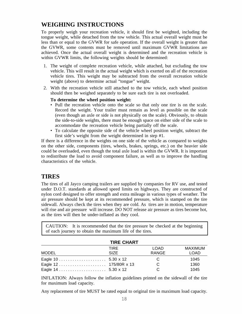
TIRE CHARTTIRE LOAD MAXIMUM
MODEL SIZE RANGE LOADEagle 10 . . . . . . . . . . . . . . . . . . . . . 5.30 x 12 C 1045Eagle 12 . . . . . . . . . . . . . . . . . . . . . 175/80R x 13 C 1360Eagle 14 . . . . . . . . . . . . . . . . . . . . . 5.30 x 12 C 1045
INFLATION: Always follow the inflation guidelines printed on the sidewall of the tirefor maximum load capacity.
Any replacement of tire MUST be rated equal to original tire in maximum load capacity.
19
VINYL TIRE COVERS (Option)TIP: To minimize the possibility of the tire “bleeding” through onto a tire cover, use aseparator (garbage bag, paper, cloth, etc.) between the tire and the cover.
WHEEL LUGSYour Eagle Folding Camping Trailer is equipped with 12" or 13" tires depending onwhich model you own. When the wheels are installed on your trailer, the lug nuts mustbe tightened according to the following specifications:
12" 85-95 foot pounds of torque13" 50-75 foot pounds of torque.
WARNING: Axles on camping trailers do not drive or steer as automobileaxles do. The motions involved in being “trailered” adds stress that canloosen lug nuts, especially during the break in period. Wheel lugs can workloose. Check and tighten wheel lugs every 10 miles, 25 miles, and 50 mileswhen the camping trailer is new or a tire is changed, and then check andtighten after periods of extensive breaking (such as coming down a steepgrade) and every 3,000 miles.
After your first trip, check the wheel lugs periodically for safety. The wheel lugs shouldthen be checked after winter storage, before starting a trip, or following extensivebraking. Over-tightening can distort wheel. Please observe the above recommendationsfor your safety and that of others.
BRAKESHydraulic surge brakes come standard on some Eagle folding camping trailers, and areoffered as an option on others. (See specification chart.) Hydraulic surge brakes operateautomatically as the brakes of the tow vehicle are applied. When the tow vehicleoperator begins to decrease speed and applies the brakes, the weight of the movingcamping trailer pushes forward and the coupler moves downward. This downwardmotion moves the plunger, which pushes the piston and rubber cup inside the mastercylinder. Brake fluid presses inside the wheel cylinder and activates the brake shoesagainst the brake drum.
BACKING YOUR TRAILER (Hydraulic)As designed, the weight of a camper pushing forward will activate the surge brakesystem. When backing a camper up a hill, the weight of the camper may activate brakes,making it difficult to continue to reverse.
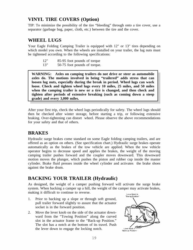
1. Prior to backing up a slope or through soft ground,pull trailer forward slightly to assure that the actuatorsocket is in the forward position.
2. Move the lever knob on the side of the actuator down-ward from the “Towing Position” along the curvedslot in the actuator frame to the “Back-up Position.”The slot has a notch at the bottom of its travel. Pushthe lever down to engage the locking notch.

20
3. Back trailer up. This latch will slide into the correct position when pulling forward.NOTE: It is extremely important to keep the master cylinder full at all times. An
empty cylinder invites moisture.
BREAKAWAY PROTECTIONThe hydraulic brake system is equipped with a breakaway cable. When towing, this cableshould be attached loosely to a frame member of the tow vehicle leaving enoughclearance so that the trailer can turn freely without actuating the breakaway protection.
Should the trailer separate from the tow vehicle, the breakaway cable will actuate themaster cylinder, locking the brakes. This will stop the trailer in the shortest possibledistance.
CAUTION: Breakaway protection should be fully released during vehicle opera-tion. Check before towing. Do not use breakaway protection as a parking brake.
FIRE EXTINGUISHERA fire extinguisher is installed near the entrance door in the RV coach. Be familiar withits location and operating instructions as printed on the extinguisher. It’s too late tobecome familiar with an extinguisher when an emergency is at hand.
The fire extinguisher is a dry chemical, non-refillable extinguisher. Do not test thisextinguisher. Doing so will cause loss of pressure making the extinguisher unusable. Theextinguisher must be discarded and replaced by a new one if any use has occurred.
SOFT SHADESSoft shades are located at each window and can be opened and closed by pressing thesmall buttons on each side of the black locks and drawing drape up or down to thedesired position.
WARNING: Keep soft shades in the upper most position while cooking onthe range top to prevent fire hazards.
WARNING: Never leave small children in the camper unattended. Childrencan become entangled in the soft shade cords.
21
SETTING UP YOUR CAMPING TRAILERWARNING: Never leave your folding camping trailer plugged in to the 120volt AC outlet while it is folded down. This would make the convertercontinue to run which can cause overheating and present a fire hazard.
Opening Your CamperAfter parking your Jayco folding camping trailer, disconnect the camping trailer from thetow vehicle. The trailer should be on level ground and the tires blocked so it will not rollaway. DO NOT USE THE STABILIZER JACKS TO LEVEL THE CAMPING TRAILER.THEY ARE INTENDED TO STABILIZE THE UNIT AND WILL NOT SUPPORT ITSWEIGHT. If your camping trailer is not level, you may experience difficulty with its setup, particularly with the fit of the entrance door.
IMPORTANT:
We recommend that well in advance of any trip, you set up your folding campingtrailer and using a garden hose, thoroughly soak the tent with a light spray of water.After the tent dries, repeat the soaking process three additional times. This processseasons the canvas and seams. DO NOT spray directly on the canvas with a highpressure hose. If you do not follow this procedure, you may experience some waterseepage during the first few exposures to rain. Let tent dry thoroughly beforestoring to prevent mildew and odors. If you note any water seepage or leaks afterseasoning your tent, let the tent dry, then spray water repellant on the INSIDE of theseams where seepage occurs. One or two applications of water repellant may benecessary to stop all water seepage in seams where thread enters the fabric. NOTE:Touching the tent canvas when it is wet can cause leakage. If leakage persists,please contact your dealer for assistance.
1. Unfasten each roof latch. (Fig. 3-2)
CAUTION: Never attempt to crank up the roof until all corner latches areunlocked and free. Fig. 3-2. NEVER LIFT ROOF WITH CARGO IN PLACE.
2. Turn thumb latch and open door at crank compartment.3. Insert the crank into the square tube and turn in a clockwise direction to raise.
(Fig. 3-3)4. Raise the roof until tent is loosely extended.
NOTE: At this point, the roof needs to be high enough to ensure that the tent willnot be in the path of the bed slide during the bed setup.
5. Lower stabilizer jacks by placing provided jack crank onto jack shaft and turnclockwise to lower. Lower jack until frame begins to rise slightly. Equalize stabi-lizer jacks for best support. You may need to adjust the stabilizer jacks two or threetimes.

22
NOTE: Road dirt and grime will sometimes make jacks difficult to operate. You mayneed to clean out before operating. To maintain stabilizer jacks keep cleanand lubricate twice a year using only silicone lubricants as oils will attractdirt and cause additional problems.
Do not place excessive weight on these jacks as they are intended tostabilize, not support the camper. The camper should be level.
NOTE: The bed braces and bed bow braces are stored under the bed mattress. (Fig. 3-7)
CAUTION: For slideout models, pull the slideout tent outside of the unit BEFOREpulling the beds out. Make sure that all tent material is clear from the bed slide.
6. Before pulling out front bed, place flat end of bed brace into slot provided on frame.Place bent hook into bracket attached to the front wall. (Fig. 3-8)
7. Pull beds out until rail hits bed stop. Distribute awning panel over bunk and placecorners of tent over corner of bed. Again, be sure beds are now extended all the wayout against stops.
WARNING: Do not use bed braces if they are bent or damaged. Replace alldamaged braces.
8. Place flattened end of straight bed brace into slot provided on frame of camper.Place angled and smashed end of straight bed brace into bed bracket near outercorner under plywood bunk bed. (Fig. 3-8)
9. Now, complete raising roof until gray limit cable is almost tight and the tent isalmost taut. DO NOT OVERTIGHTEN. (Fig 3-4)
CAUTION: If the limit cable is raised too high, lifter system/tent damage couldoccur and the door will not fit properly.
FOR MODELS WITH SLIDEOUTa. Unlock Slideout. (Fig. 3-5) Lock is located on the outside of the folding camping
trailer. (Model #14SO does not have a lock.)b. Pull out slideout using the handle(s) located on the side of the slideout.
CAUTION: Do not extend slideout before pulling beds out.
c. Lock slideout.d. Pull tent flaps located on the side of the slideout out over edge and attach to Velcro.e. Enter unit and set up kitchen flip-top. Attach stove grate.
10. Inside unit, for the bed and slideout tent set up, insert bed bow brace at the bed bowconnector. Push bed bow outward and upward while pressing on button farthestfrom the end and slip into bracket mounted on roof. Release button. (Fig. 3-6)
TO INSTALL DOOR11. Unlatch twist locks holding door to roof. Swing down the double hinged, self-
storing screen door. Drop channel of lower edge of screen door over entrancedoor, guiding locating pins into door jamb extrusion. If door does not alignproperly, check jacks to make sure they are adjusted correctly and check camperfor levelness.
23
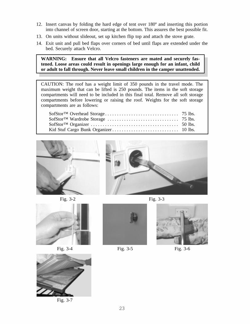
12. Insert canvas by folding the hard edge of tent over 180º and inserting this portioninto channel of screen door, starting at the bottom. This assures the best possible fit.
13. On units without slideout, set up kitchen flip top and attach the stove grate.14. Exit unit and pull bed flaps over corners of bed until flaps are extended under the
bed. Securely attach Velcro.
WARNING: Ensure that all Velcro fasteners are mated and securely fas-tened. Loose areas could result in openings large enough for an infant, childor adult to fall through. Never leave small children in the camper unattended.
CAUTION: The roof has a weight limit of 350 pounds in the travel mode. Themaximum weight that can be lifted is 250 pounds. The items in the soft storagecompartments will need to be included in this final total. Remove all soft storagecompartments before lowering or raising the roof. Weights for the soft storagecompartments are as follows:
SofStor™ Overhead Storage . . . . . . . . . . . . . . . . . . . . . . . . . . . . . . . 75 lbs.SofStor™ Wardrobe Storage . . . . . . . . . . . . . . . . . . . . . . . . . . . . . . 75 lbs.SofStor™ Organizer . . . . . . . . . . . . . . . . . . . . . . . . . . . . . . . . . . . . . 50 lbs.Kid Stuf Cargo Bunk Organizer . . . . . . . . . . . . . . . . . . . . . . . . . . . . 10 lbs.
Fig. 3-2 Fig. 3-3
Fig. 3-4 Fig. 3-5 Fig. 3-6
Fig. 3-7

24
Fig. 3-8
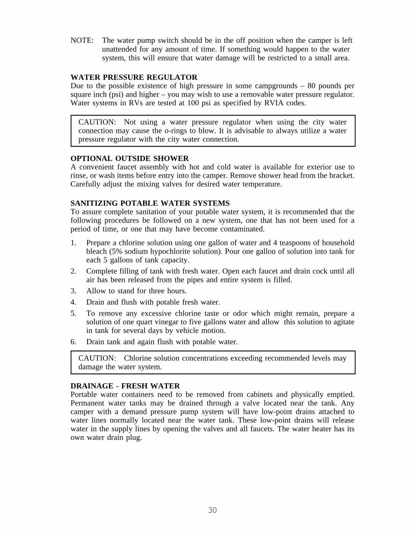
FOR INSIDE/OUTSIDE GALLEY (MODEL 12MK ONLY)To use outside:
1. Open the outside doors.2. Remove the tie down strap.3. Lift up on the release lever (Fig. 3-9).
This will release the latch (Fig. 3-10)so the galley will slide into position.
4. Using the handle, pull the galley outuntil it latches in place.
5. Set up the stove cover when using thestove. (Fig. 3-11)
To move galley in:
CAUTION: Do not lift up on the galley while sliding it into the unit. The stovecover or sink handles could catch on the door frame.
1. Make sure the stove cover is laid down onto thestove.
2. Lift up on the release lever. (Fig. 3-9)3. Slide the galley into the unit until it latches in
place.4. If preparing for travel, make sure the tie down
strap is secured. (Fig. 3-13)
Fig. 3-9Fig. 3-10
Fig. 3-11
25
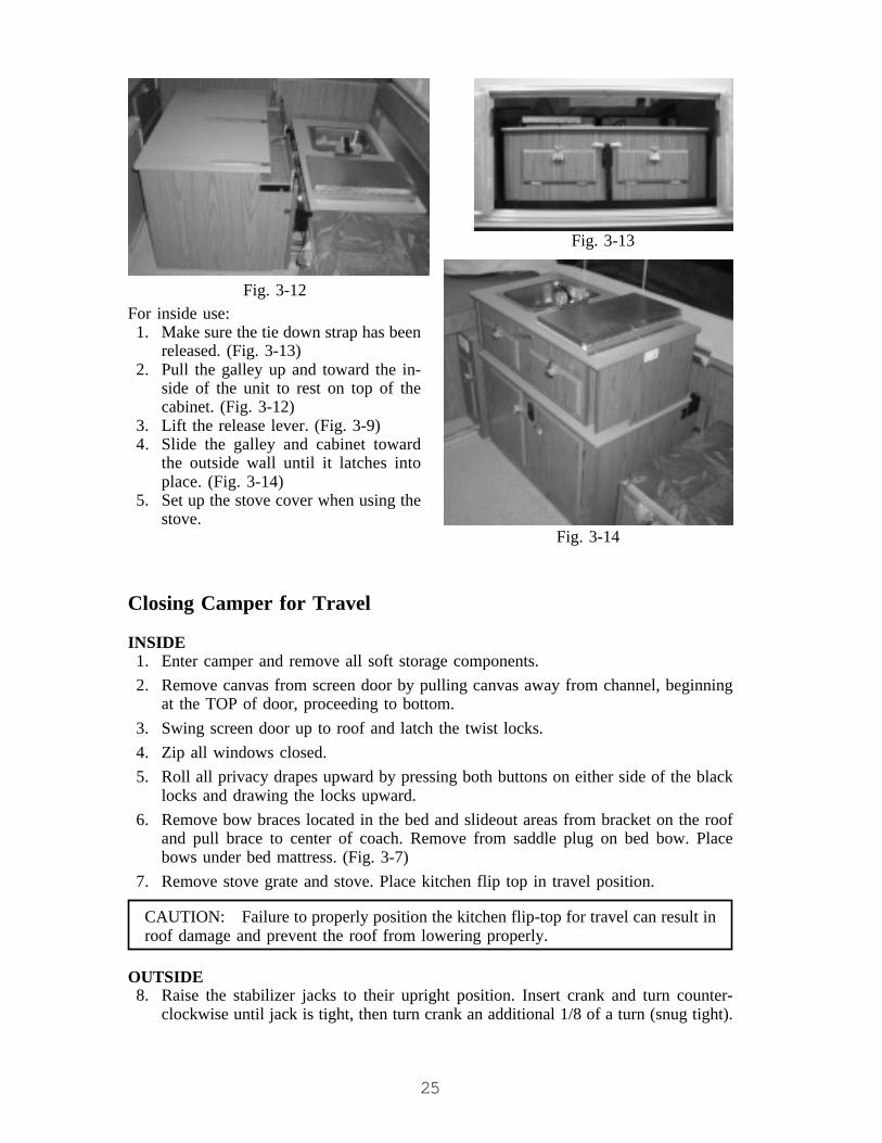
For inside use:1. Make sure the tie down strap has been
released. (Fig. 3-13)2. Pull the galley up and toward the in-
side of the unit to rest on top of thecabinet. (Fig. 3-12)
3. Lift the release lever. (Fig. 3-9)4. Slide the galley and cabinet toward
the outside wall until it latches intoplace. (Fig. 3-14)
5. Set up the stove cover when using thestove.
Fig. 3-12
Fig. 3-13
Closing Camper for Travel
INSIDE1. Enter camper and remove all soft storage components.2. Remove canvas from screen door by pulling canvas away from channel, beginning
at the TOP of door, proceeding to bottom.3. Swing screen door up to roof and latch the twist locks.4. Zip all windows closed.5. Roll all privacy drapes upward by pressing both buttons on either side of the black
locks and drawing the locks upward.6. Remove bow braces located in the bed and slideout areas from bracket on the roof
and pull brace to center of coach. Remove from saddle plug on bed bow. Placebows under bed mattress. (Fig. 3-7)
7. Remove stove grate and stove. Place kitchen flip top in travel position.
CAUTION: Failure to properly position the kitchen flip-top for travel can result inroof damage and prevent the roof from lowering properly.
OUTSIDE8. Raise the stabilizer jacks to their upright position. Insert crank and turn counter-
clockwise until jack is tight, then turn crank an additional 1/8 of a turn (snug tight).
Fig. 3-14

26
CAUTION: DO NOT push beds or slideout in until ALL Velcro is detached. Pushbed and slideout in COMPLETELY before beginning to lower roof. Failure to pushin beds and slideout completely BEFORE lowering roof can damage tent compo-nents. Your Jayco Limited Warranty does not cover this damage.
FOR MODELS WITH SLIDEOUTSa. Unfasten the Velcro® and snaps from the slideout and place the tent inside the
slideout.b. Unlock the slideout. (Model #14SO does not have a lock.)c. Push the slideout into travel position.d. Lock the slideout. (Model #14SO does not have a lock.)e. Pull the tent out of the slideout to ensure that the bed slides do not rip the tent.
CAUTION: Make sure the slideout tent is pulled to the outside of the unit before thebeds are pushed in. Failure to do this could result in cutting the slideout area tent.
9. Unfasten all Velcro located under beds.
10. Remove straight bed braces and push beds in carefully and completely.11. Remove curved bed braces. Place all braces under bed mattresses carefully. (Fig. 3-7)12. Lower roof half to two-thirds down. Reach inside and distribute awning panel of
tent and drape EVENLY across beds and slideout (if applicable).
13. Continue to lower roof until final 6-8". Using both hands and arms, push tent fromeach side, front and rear, into the center of camper evenly and carefully continue tolower roof.
14. Attach roof latches to clips (Fig. 3-2). Due to air pockets, the roof may need to bepushed down with your hand the last 1-2".
15. Before removing crank, tighten cable system by turning crank in the “UP” move-ment to make it taut taking caution not to overtighten. This will place slight tensionon cable system and avoid cables becoming loose and entangled.
CAUTION: It is very important to place tension on the cable system to preventthem from becoming tangled. If the cables become tangled, it could lead tobreakage of the lifter cables when the roof is raised.
16. Remove crank and place in storage area inside camper.17. Close and latch door to crank compartment.
CAUTION: Excessive snow, 8" or more, or ice, 2" or more, places excessiveweight on roof. Such excessive quantity of snow or ice should be removed asneeded. Care MUST be exercised as not to damage roof material when removingsnow & ice. Excessive weight can damage the roof, seals, etc. Water leaks and poorfit or operation are the results of this damage.

27
Parts List for Front Beds Eagle Folding Camping Trailers
1. Bed Bow 3. Bed Brace 5. Saddle Plug2. Bow Brace 4. Steel Bed Slide 6. Bracket
CANOPY SETUPYour canopy has been designed and built with quality material to give you years oftrouble free service with low maintenance.
Read these instructions fully before beginning setup. Become familiar with each pole, itsdescription and where it belongs. Refer to Fig. 3-15
One person can do the setup, but two people will make it easier.
1. Open zipper and unroll canopy fabric.2. Insert the two end divider bars “C” (with gray caps) and center spacer bar “D” (7/
8" tube) into front pocket of the canopy. These bars may be left in the canopyduring travel or storage, but should be removed during winter storage to avoidcorrosion.
3. Assemble the two parts of a tension rafter, Pole “A.” Insert the peg through the“eye” of the twist pole “B” and then through the hole in the middle of the centerspacer bar “D.” Compress tension rafter and place in the center of the roof sideboard, as pictured. The metal tip from the tension rafter will rest against the roofmetal or the canopy bag.
4. If no screen room is being installed, repeat step #3 on the front and rear tensionrafter, inserting the end of the tension rafter through twist poles “B” and the enddivider bars “C.” Position tension rafter as in step #3.
5. After all the poles are installed:a) Adjust the canopy to fit properly.b) Adjust the height of the canopy with the twist lock poles.c) Install the three stakes to anchor the canopy in case of strong winds.
CAUTION: Always install the stakes to avoid wind damage to the poles and thefabric. In severe wind it is best to remove the canopy. Wind and rain damage are notcovered by warranty.

28
Fig. 3-15
SCREEN ROOM SETUP1. The canopy must be setup through step #3 before attempting to attach the screen
room. (See Canopy Setup.)2. Open, unfold and spread screen room under canopy area. Enclosure must be on the
outside of the twist poles. A grassy area or clean floor is suggested.3. Each upper side panel has a pocket sewn into fabric. Slide a two-piece tension rafter
into pocket with the white crutch tip to be placed against side panel of the roof.Insert crutch tip at outer edge, and push in toward unit.
4. Insert peg through the “eye” of the twist pole “B” and then through the hole at theouter end of end divider bar “C”. The white rubber crutch tip will rest against roofmetal or the canopy bag. Install both ends.
5. Attach the Velcro hook sewn to the inner side of canopy to the Velcro loop sewn tothe outer side of the screen room, full length.
6. Wrap lifter post covers around posts and attach with Velcro.7. Ensure all snaps are secure, fastening skirt to frame of unit.8. Attach Velcro from skirt to Velcro on screen room lower corners.9. Adjust three twist poles “B” so bottom of screen room is just touching the ground.
10. Install the 7 stakes through the screen room loops to protect against wind damage.

29
CHAPTER 4THE SYSTEMS
PLUMBING SYSTEM
Fresh WaterAvailable in your Jayco folding camping trailer areseveral types of fresh water tanks and filling meth-ods based on options purchased. Each type isexplained below along with its operation.
1. A five gallon portable water tank is locatedinside the cabinet nearest the sink. A 3/8" non-pressure hose is attached to the container.
2. A ten gallon (or larger) water tank may be permanentlyinstalled in your camper. To fill the tank, open the lid asshown. (Fig. 4-1) Insert or hold the water hose and fill tothe desired capacity. The tank has an overflow outlet, butcare must be taken to not overfill it.
CAUTION: Overfilling the tank can potentially pressurize itand cause leakage.
3. Water may be received into the system through a directhookup, referred to as “city water connection,” (Fig. 4-2) when attached to entrysupply and water hose.
4. Operation of hand pump:Tank Water - place handle into vertical position, using short strokes. Allow 10-20seconds to prime pump and fill the water lines before filling sink.City Water - move handle down slowly to open “CW” valve. Hold in this positionfor quick use. Press down completely to lock for continuous water flow.
WARNING: Handle should be in the TANK WATER position whenconnecting city water to avoid city water spill.
Depress handle while traveling. Spout will swivel over 90° for your convenience. Thespout is NOT a handle.
5. On camping trailers with the deluxe plumbing package, or shower/toilet options,there is an additional 12-volt DC demand pump to supply water needs. This devicerequires 12-volt DC power from either a deep cycle battery, or a converter when120-volt AC power is available. A 12-volt DC switch is located on a cabinet nearthe pump to turn the power on or off. When 12-volt DC power energizes the pump,it will self-prime and fill water lines and components. When pressure achievesapproximately 40-45 pounds, the pump will shut off and restart when the pressuredrops to 21 pounds. Some cycling of the pump may occur, depending on the volumeof water used. A check valve is located inside the pump to prevent water fromflowing into the supply tank. It is suggested that you turn the 12-volt DC power offat the switch when using direct water supply.
Fig. 4-2
Fig. 4-1
30
NOTE: The water pump switch should be in the off position when the camper is leftunattended for any amount of time. If something would happen to the watersystem, this will ensure that water damage will be restricted to a small area.
WATER PRESSURE REGULATORDue to the possible existence of high pressure in some campgrounds – 80 pounds persquare inch (psi) and higher – you may wish to use a removable water pressure regulator.Water systems in RVs are tested at 100 psi as specified by RVIA codes.
CAUTION: Not using a water pressure regulator when using the city waterconnection may cause the o-rings to blow. It is advisable to always utilize a waterpressure regulator with the city water connection.
OPTIONAL OUTSIDE SHOWERA convenient faucet assembly with hot and cold water is available for exterior use torinse, or wash items before entry into the camper. Remove shower head from the bracket.Carefully adjust the mixing valves for desired water temperature.
SANITIZING POTABLE WATER SYSTEMSTo assure complete sanitation of your potable water system, it is recommended that thefollowing procedures be followed on a new system, one that has not been used for aperiod of time, or one that may have become contaminated.
1. Prepare a chlorine solution using one gallon of water and 4 teaspoons of householdbleach (5% sodium hypochlorite solution). Pour one gallon of solution into tank foreach 5 gallons of tank capacity.
2. Complete filling of tank with fresh water. Open each faucet and drain cock until allair has been released from the pipes and entire system is filled.
3. Allow to stand for three hours.4. Drain and flush with potable fresh water.5. To remove any excessive chlorine taste or odor which might remain, prepare a
solution of one quart vinegar to five gallons water and allow this solution to agitatein tank for several days by vehicle motion.
6. Drain tank and again flush with potable water.
CAUTION: Chlorine solution concentrations exceeding recommended levels maydamage the water system.
DRAINAGE - FRESH WATERPortable water containers need to be removed from cabinets and physically emptied.Permanent water tanks may be drained through a valve located near the tank. Anycamper with a demand pressure pump system will have low-point drains attached towater lines normally located near the water tank. These low-point drains will releasewater in the supply lines by opening the valves and all faucets. The water heater has itsown water drain plug.

31
DRAINAGE - WASTE WATERConnect a hose to the drainage outlet (Fig. 4-3) and drain sinkeither to a container to hold waste water or to a direct sewer inletsupplied by some campgrounds. Most campgrounds and somestates prohibit sewer water drainage onto the open ground.
GRAY WATER HOLDING TANK - OPTIONNo special preparation is required. However, placing a smallquantity of chemicals into this tank, such as baking soda or aThetford chemical, will reduce odors from food particles in thesystem.
CAUTION: We recommend that you DO NOT travel with waste in your holdingtanks. Full holding tanks are not calculated into the cargo carrying capacity of theunit and the extra weight will greatly diminish the cargo weight available to you,possibly causing you to exceed the gross vehicle weight rating of the unit. This candamage suspension components, such as springs, tires and axles. If your model hasthe holding tanks located behind the axles, the weight of a full tank will reduce thehitch weight. Sway and other handling difficulties can be the result of the hitchweight being too light. If you are dry camping and cannot immediately empty thetanks, use caution when towing and maintain lower speeds for better control of thetrailer until you reach a dumping station.
Fig. 4-3

32
Cassette Toilet (Option)
PREPARING FOR USE1. Open access door on the right side of the camper and swing
out fresh water fill funnel.2. Fill the water tank with clean fresh water using a hose or
jerrycan until water funnel level reaches neck. Tank capac-ity is 3.9 gallons.
3. Replace cap. Swing water fill funnel inward until it touchesside of water tank. NOTE: 150 ml of water will remainin fill bottle when fresh water tank is empty.
4. Remove the cassette by pressing the retaining clip down.5. Remove cassette by pulling straight out. When cassette hits
stop, tilt downward slightly and remove (stop for safetywhen cassette is full).
6. Position tank vertical and swivel pour-out spout upward.7. Remove cap. Remove Aqua Kem® from storage compart-
ment. Add given amount of Aqua Kem® through pour-outspout. Add water until the bottom of the cassette is com-pletely covered with liquid.Replace cap and return pour-out spout to its original storedposition. NOTE: The cap of the pour-out spout is packedtogether with the instructions for use. Hotter weather orlonger retention time may require addition of more AquaKem®.
CAUTION: Never add Aqua Kem® through the valveblade or the toilet bowl. Pressure (due to heat and altitudechange) can build up in the cassette tank and cause thecontents of the bowl to splash upward upon opening thevalve blade, if opened too fast.
8. Slide the cassette, pour-out spout facing outside, into thecamper through the access door. Be aware that sliding coveris placed correctly; the two arrows on top have to bepointed towards each other.
9. Make sure the cassette is locked with the cassette retainingclip.
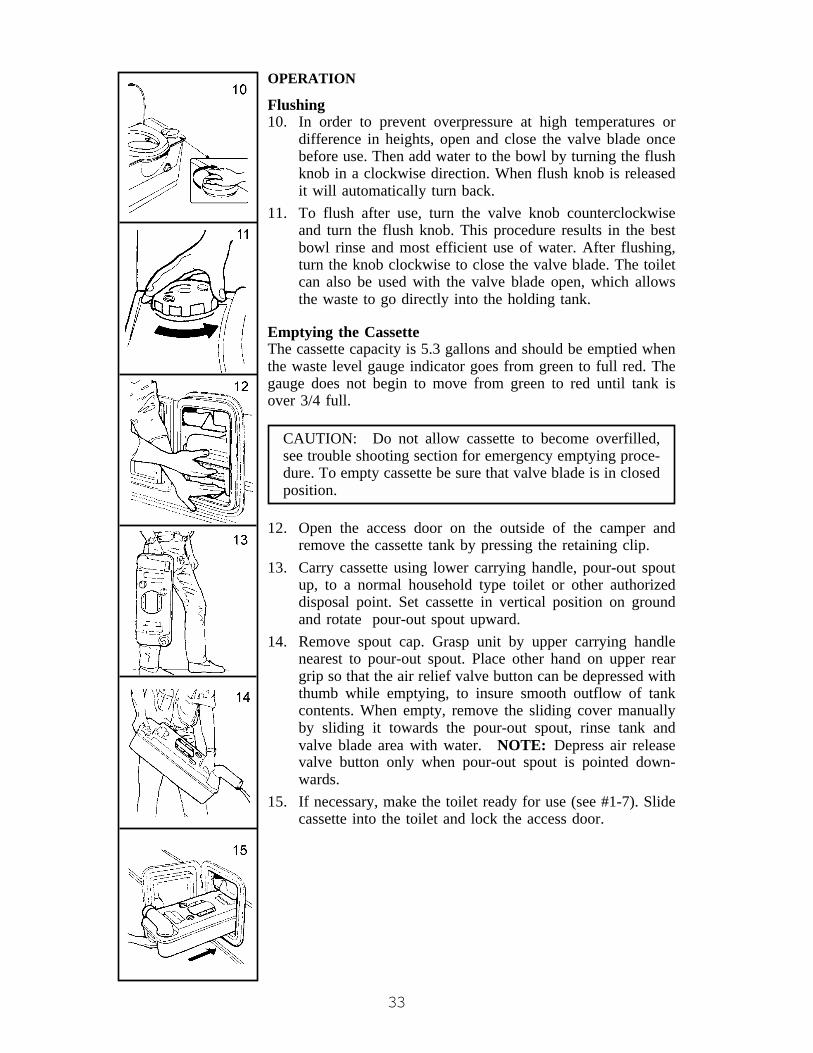
33
OPERATION
Flushing10. In order to prevent overpressure at high temperatures or
difference in heights, open and close the valve blade oncebefore use. Then add water to the bowl by turning the flushknob in a clockwise direction. When flush knob is releasedit will automatically turn back.
11. To flush after use, turn the valve knob counterclockwiseand turn the flush knob. This procedure results in the bestbowl rinse and most efficient use of water. After flushing,turn the knob clockwise to close the valve blade. The toiletcan also be used with the valve blade open, which allowsthe waste to go directly into the holding tank.
Emptying the CassetteThe cassette capacity is 5.3 gallons and should be emptied whenthe waste level gauge indicator goes from green to full red. Thegauge does not begin to move from green to red until tank isover 3/4 full.
CAUTION: Do not allow cassette to become overfilled,see trouble shooting section for emergency emptying proce-dure. To empty cassette be sure that valve blade is in closedposition.
12. Open the access door on the outside of the camper andremove the cassette tank by pressing the retaining clip.
13. Carry cassette using lower carrying handle, pour-out spoutup, to a normal household type toilet or other authorizeddisposal point. Set cassette in vertical position on groundand rotate pour-out spout upward.
14. Remove spout cap. Grasp unit by upper carrying handlenearest to pour-out spout. Place other hand on upper reargrip so that the air relief valve button can be depressed withthumb while emptying, to insure smooth outflow of tankcontents. When empty, remove the sliding cover manuallyby sliding it towards the pour-out spout, rinse tank andvalve blade area with water. NOTE: Depress air releasevalve button only when pour-out spout is pointed down-wards.
15. If necessary, make the toilet ready for use (see #1-7). Slidecassette into the toilet and lock the access door.

34
Shower System (Option on Some Models)The shower system in the folding camping trailer is designed to provide an easy andconvenient method of showering while in the privacy of your personal camper.
To operate the shower facility, observe the following steps:
1. Open shower countertop and secure lock.2. Install shower hose and head. Observe 2 brackets to mount shower head, first
bracket beside faucet is for travel and storage, second bracket mounted on the roofto use when taking a shower.
3. Prepare your curtains, shower and privacy to prevent water from reaching areasother than shower pan.
4. Ensure water heater is in operation.5. Open faucets and adjust to desired temperature.6. All used water will drain in gray water tank located below camper floor.7. To drain gray holding tank, attach a 1¼ x ¾" swivel adaptor and hose to termination
valve. After attachments are secured and hose placed in proper approved facility,open valve and drain tank. Rinse gray water tank as desired with fresh water.
NOTE: The water heater has a six gallon capacity. The holding tank has a ten galloncapacity.
CAUTION: In units with the bath/shower option, ensure the shower head issecured in the wall holder before closing your camper for moving or storage. If theshower head is left in the ceiling holder when the camper is closed, damage canresult.
Winterizing Camping Trailer
NON-POWER SUPPLY SYSTEMS1. Drain tank. The remaining small quantity of water in a plastic tank will not damage
tank by freezing.2. Ensure all water has been drained from the hand pump by using an up and down
motion. No anti-freeze is needed for hand pumps.3. Pour one pint of non-toxic anti-freeze into trap to ensure that the small amount of
water left in trap assembly does not freeze.4. Faucets should be left in the open position to allow air movement until dry.
DEMAND OR POWER PLUMBING SYSTEMS1. Drain all tanks and fresh water lines by opening tank drain valve V3 & V4 (Fig. 4-4).
Tank drain is outside left front corner of camper. Also open all faucet valves for airto replace water space. Lines may not drain completely if faucets are not open.
2. Close valve V3 & V4 and . . .3. Close Valve V1 to prevent anti-freeze from entering the tank.4. Open valve V2 and insert siphon hose into container full of non-toxic RV anti-
freeze.5. Start demand pump to circulate anti-freeze throughout system.

35
WARNING: DO NOT use Ethylene Glycol (automotive anti-freeze) orMethanol (windshield washer anti-freeze) in your fresh water system be-cause they are harmful and MAY BE FATAL if swallowed. USE ONLYNON-TOXIC ANTI-FREEZE.
Fig. 4-4
DRAIN TRAPSSince not all water can be drained from sinks and shower trap assemblies, pour 1 pint ofnon-toxic anti-freeze into traps.
OPTIONAL THETFORD CASSETTE TOILETThe Thetford Cassette Porta Potti is easily winterized for storage or cold weather use.
1. Empty the fresh water tank using drain tube. Position drain tube outward throughdoor opening. Pull off the plug and drain water from tank. (Fig. 4-5)
2. Flush a few times by turning the flush knob to drain the pump assembly. (Fig. 4-6)NOTICE: Cassette has to be in. Empty the cassette afterwards.
3. Empty the water fill funnel by pulling the bottle away from tank. Remove smallwater cap at fill bottom, allowing water to drain from water funnel. (Fig. 4-7)NOTE: Do not tighten caps, this helps in keeping unit dry.
Fig. 4-5 Fig. 4-6 Fig. 4-7
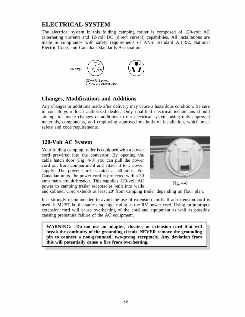
36
Fig. 4-8
ELECTRICAL SYSTEMThe electrical system in this folding camping trailer is composed of 120-volt AC(alternating current) and 12-volt DC (direct current) capabilities. All installations aremade in compliance with safety requirements of ANSI standard A.1192, NationalElectric Code, and Canadian Standards Association.
Changes, Modifications and AdditionsAny changes or additions made after delivery may cause a hazardous condition. Be sureto consult your local authorized dealer. Only qualified electrical technicians shouldattempt to make changes or additions to our electrical system, using only approvedmaterials, components, and employing approved methods of installation, which meetsafety and code requirements.
120-Volt AC SystemYour folding camping trailer is equipped with a powercord prewired into the convertor. By opening thecable hatch door (Fig. 4-8) you can pull the powercord out from compartment and attach it to a powersupply. The power cord is rated at 30-amps. ForCanadian units, the power cord is protected with a 30amp main circuit breaker. This supplies 120-volt ACpower to camping trailer receptacles built into wallsand cabinet. Cord extends at least 20' from camping trailer depending on floor plan.
It is strongly recommended to avoid the use of extension cords. If an extension cord isused, it MUST be the same amperage rating as the RV power cord. Using an improperextension cord will cause overheating of the cord and equipment as well as possiblycausing premature failure of the AC equipment.
WARNING: Do not use an adapter, cheater, or extension cord that willbreak the continuity of the grounding circuit. NEVER remove the groundingpin to connect a non-grounded, two-prong receptacle. Any deviation fromthis will potentially cause a fire from overheating.
37
GFCIEach unit contains a Ground Fault Current Interrupter (GFCI) outlet. This specialbreaker has been designed to reduce the possible injury caused by electrical shock.
An example of ground fault current is the current which would flow through a personwho is using or touching an appliance with faulty insulation and, at the same time, is incontact with an electrical ground such as a plumbing fixture, wet floor, or earth.
The GFCI breaker will not protect against short circuits or overloads. The circuit breakeror fuse in the electrical panel which supplies power to the circuit provides this protec-tion.
When the GFCI breaker is tripped, it has interrupted ground fault current caused by suchthings as faulty insulation or wet wiring inside some appliance or equipment connectedto the circuit. The faulty equipment should be repaired before is it used again.
This special breaker should be tested monthly while the camping trailer is being used.See the manufacturer’s owner’s manual for more instructions.
To prevent accidental electrical shock, insure that the ground pin on the attachment plugcap is intact to the earth ground through the RV park receptacle. When plugged into areceptacle with no provision for the third pin, use an adapter with a pigtail that can beconnected to the receptacle box, with the grounding circuit completed through theground pin or RV park receptacle box. Any accidental short of a live circuit conductorwill trip the circuit breaker indicating a shorted circuit. You should be certain that thepolarity of the external power is not reversed, in order to avoid harm to appliances andpersonal electrical shock. Polarity indicators may be purchased in most electrical andhardware stores.
Testing Instructions GFCI1. Plug a lamp or radio into the receptacle on the face of the GFCI.2. Push and release the RESET button.3. The lamp should light at this time.4. Press the TEST button.5. RESET button should pop out indicating “trip” and the lamp should go out. (If the
GFCI is manufactured with an indicator light, the light should glow when the devicehas tripped.)
6. If the GFCI did not trip, do not use. The ground fault protection is no longerworking and the GFCI may not be working properly.
7. If the GFCI did not “trip,” call a qualified electrician. DO not use until anelectrician has serviced this device.
8. To restore power after “tripping,” press the RESET button. It must remain in. (If anindicator light is furnished, it will be off.)
38
Air Conditioner (Option)To meet State, National, and RVIA codes as well as support from manufacturer ofcamper, you need to have installed a special kit to provide proper operation and energyfor successful enjoyment. To comply with all applicable codes, it must have the following:
1. 20-amp receptacle with 12 gauge wire.2. 20-amp power cord to feed air conditioner.3. Two twist caps.
The weight limit for air conditioners is 110 lbs. Exceeding this weight can damage theroof and lifter system which will not be covered by your Jayco Limited Warranty.DuoTherm and RVP brands usually are acceptable for folding camping trailer roofinstallations. Other brands may be used if the weight is 110 lbs. or less and the interiorshroud fits around the roof components.
DuoTherm DuoThermBTU BriskAir Penguin Coleman7,100 74 lbs. 88 lbs. 75 lbs. use #6727
11,000 92 lbs. 104 lbs. 92 lbs. use #6757 A, D, or E Series13,500 96 lbs. 109 lbs. 95 lbs. use #6757 A, D, or E Series
WARNING: Any electrical installation that does not meet the criteria maydamage the electrical system and cause problems which will not be coveredunder your Jayco Limited Warranty.
WARNING: Follow the wiring listed below as it attaches to the airconditioner.
Outer Smooth Protective Covering = Positive BlackOuter Ribbed Protective Covering = Neutral WhiteCenter Smooth Protective Covering = Ground Green
Failure to wire as specified will send reversed polarity in the air condi-tioner, causing a potentially dangerous situation with the possibility of fire.
Follow the air conditioner installation instructions as supplied with the air conditioner.Connect the 20-amp power cord to the air conditioner as listed above warning. Notch theinterior air conditioner shroud so the cord can pass between it and the roof. Using p-clamp, secure the cord to the outer edge of ceiling and let it hang down the side of thetent. It is code violation to run the 120-volt cord through a conduit of any type ofcovering. The cord must be visible.
39
12-Volt DC SystemThe 12-volt DC system is composed of numerous items such as convertor, battery, fusesand lights. Explanation on these items will follow in this section.
CONVERTERThe converter utilizes 120-volt AC power and transforms this energy into 12-volt DCpower, which is used inside of the camper. 12-volt DC energy supplies power to alllights, furnace blower, and water pump (option).
The converter is a technologically advanced 20-amp PWM “switch mode” type, that canbe used with computers. It is self-contained with a built in circuit breakers and DC fuses.A quiet cooling fan provides ventilation and is thermally protected to shut down andcycle back on if overheating occurs.
WARNING:• Turn off all interior lights before folding the camper for transit as the
bulbs may cause a fire hazard in the folded position and burn holes in tent.• Do not block converter ventilation.
InteriorAll 12-volt power comes from the converter or the black lead in the wire harness fromthe tow vehicle battery. Remember, to receive power from the converter you must havea 120-volt energy source available. 120-volt power may be turned off or on by switchingthe 120-volt breaker in the converter.
The “bunk” light will attach to the bed bow brace with a clip on the back of the light. Tooperate the light with 12-volt power, plug the cord into the receptacle located on theceiling light, front or rear. A switch to control the bunk light is built into the lightassembly.
A unit with a porch light will have the on/off switch built into the light assembly. Thebunk light may also be used outside by clipping it to the optional canopy. When attachedto the canopy, the bunk light will be connected to the porch light receptacle.
Batteries (Option)All Jayco folding camping trailers are pre-wired to accept an auxiliary battery if sodesired. The battery must be hooked up directly to red (positive) and white (negative)wires on trailer hitch, harness and frame using nothing less than 10 gauge wires.
The auxiliary battery may be installed to avoid discharging tow vehicle battery when110-volt power is not available.
Camping trailers with power lift system will have a battery and box installed as part ofthe option package.
All battery packages installed by the manufacturer will have an “in-line” fuse and holderincluded for protection.
CAUTION: When drawing current from the tow vehicle battery, be sure to avoiddraining battery to a low point that the tow vehicle will not start.

40
All Jayco folding camping trailers have ceiling light circuit directed through a mastershut-off switch to prevent 12-volt current flow to ceiling lights with roof lowered.Periodically test light and switch to be sure switch adjustment is correct. Switch islocated along bottom edge of roof on roadside.
WARNING: The converter output is not intended to power the optional 3-way refrigerator. When the folding camping trailer is parked and the powercord is plugged in, set the 3-way refrigerator to “AC Power.” A “DC” modeis to be used when traveling and will pull its power from the auxiliary batterycharge line. While camping without available AC power, utilize the “LP Gas”mode.
Please note, battery warranties are prorated.
Battery ChargerThe converter will automatically monitor and charge the auxiliary battery up to a 20-amprate. In order to maintain the battery, one of two things is recommended:
• The battery can be stored in a fully charged condition.• The battery can be hooked to a battery charger once per month.Battery terminals and connectors, including vehicle frame connections, should be cleanedthoroughly, securely fastened, and coated with a silicone dialectic compound or petro-leum jelly.
Trailer Hitch PlugAll exterior vehicle lights are 12-volt and wired in accordance with the standardaccepted color code:
6-Way Poly Mold with Cover
10G RED . . . . . . . . . . . . . . . . . . . . Charge Line16G GREEN . . . . . . . . . . . . . . . . . . Clearance10G WHITE . . . . . . . . . . . . . . . . . . Ground16G RED A . . . . . . . . . . . . . . . . . . Left Turn/Stop16G BROWN . . . . . . . . . . . . . . . . . Right Turn/StopOptional 12 G BLUE . . . . . . . . . . . Electric Brakes
The connector between tow vehicle and trailer may build up corrosion over a period oftime. This is caused by weather elements, and should be cleaned occasionally to insuregood electrical contact.
For the electric brake option, a brake controller must be installed to power the blue wirewhen the brakes are applied. Included is a brake-away switch for emergency stopping.See your dealer for installation.
41
Fuse and Bulb ChartFUSES CircuitOperation Location Number Fuse Size TypeInterior Lights, Water Pump in converter 1 15 BladeRefrigerator in converter 2 15 BladeFurnace in converter 3 15 BladeBattery Pac (exterior) in line by battery 4 20 BladeLP Detector behind LP N/A 1 Blade
Some components listed above are options.
BULBSInterior . . . . . . . . . . . Ceiling, Bunk Lights . . . . . . . . #921Exterior . . . . . . . . . . Porch Light . . . . . . . . . . . . . . . #912Exterior . . . . . . . . . . Tail Light / Signal . . . . . . . . . #1157Exterior . . . . . . . . . . Clearance . . . . . . . . . . . . . . . . #194
WARNING: Do not replace circuit breakers or fuses with a higher currentrating than those supplied with the new camping trailer. Over-fusing cancause a fire hazard by overheating the electrical wiring.
When attaching wire leads to a tow vehicle, carefully insulate all connections forprotection. Follow the instructions on instruction sheet provided with covered harness.
LP FUEL SYSTEMIt is because of the LP gas system that your RV has the convenience of a refrigerator,stove, water-heater, and furnace. This system has containers that contain the fuel andalso regulators to control the pressure of the fuel and supplies the gas vapor to thevarious appliances. When correctly used, the LP system is very effective and will ensurethe comfort and added convenience for your vehicle. This system is also potentially verydangerous and should be used with care.
Liquefied petroleum (LP) is a product that is refined from crude oil through naturalgases. LP gas is a colorless and odorless gas that in the liquefied state resembles water.An odorant is added as a warning agent. This is usually a sulfur compound which givesthe gas the rotten egg, stinky, skunk oil odor. It is extremely important to becomefamiliar with the odor associated with LP gas.
LP gas is stored in a pressurized canister in a liquid state. As the fuel is released from thecanister, it becomes vapor that is needed for the operation of the appliances. In the liquidstate, gas should not run through the appliances. A liquid fuel will damage the o-rings inthe valves and also leave a sticky, oily residue causing poor or no operation in theregulator.
LP ContainerThe tank or bottle is a D.O.T. approved container to hold fuel in liquid form, and isnormally a 20# or 30# capacity. The open/close valve is to be closed at all times unlesshooked up to LP gas system or filling container. When container is disconnected fromhose and P.O.L. connection, install P.O.L. plastic plug as attached to container. This is
42
required by RV industry, Gas Association, and for your own safety. Do not allowcontainer (filled or empty) to move or roll around while transporting to and from fillinglocation.
WARNING: Because your vehicle has exterior combustion air inlets, allappliance pilot lights should be turned off during gasoline or propane refuel-ing. Laws in some states require this.
Servicing and Filling LP ContainersFilling an LP container correctly is very important and should be performed by aqualified person who knows the proper safety procedures and inspecting containers. Anynew container must be carefully purged for best performance and must NEVER BEOVERFILLED.
Caution: DO NOT use tools to open or close tank valve. HAND TIGHTEN ONLY.
LP gas expands 1½% for each 10° increase in temperature. It is imperative to leavesufficient space inside the container to allow for the natural expansion of gas duringwarmer weather. Each propane container is equipped with an overfill device built intothe main valve. This device must remain open during the filling. When the container isfilled to 80%, the maximum level for safety, a liquid will appear replacing the vapor.Stop filling immediately and close both valves; HAND TIGHTEN ONLY.
WARNING: A propane container should never be filled beyond 80% of itscapacity.
If your tank becomes overfilled and is not allowed to “bleed off” before installation tothe RV system, it may gain pressure from exposure to direct sunlight and will begin“blowing off” pressure from the overflow valve. This will be detected by the strong odoraround the tanks. Keep open flames away from this area. It is best to find a technicianqualified in releasing an overfill from the container. If that is not possible, remove thebottle, take it to a safe area at least twenty-five feet from any source of combustion, and“bleed off” the excess pressure by opening the valve slightly and closing it whendischarge has been sufficient, one to two minutes.
WARNING: LP gas containers are equipped with safety devices, which relieveexcess pressure by discharging gas into the atmosphere. Do not bring or storeLP gas containers, gasoline or other flammable liquids inside the recreationalvehicle. Disregarding this warning may result in fires or explosions.
When an LP container gets low, sometimes there is a concentration of garlic-like odorwhich may be mistaken for a gas leak. After a change over to a full tank, the odor usuallywill disappear. If not, turn off the LP container(s) and have the system checked by aqualified technician.

43
1. Knob to open valve to fill or to use camper.2. Complete valve assembly.3. “10%” valve, small brass knob or slot screw.4. Container mounting stand.
A warning label has been located near the LP gas container. This label reads:
THIS GAS PIPING SYSTEM IS DESIGNED FOR USE OFLIQUEFIED PETROLEUM GAS ONLY. DO NOT CONNECTNATURAL GAS TO THIS SYSTEM. DO NOT FILLCONTAINER(S) TO MORE THAN 80 PERCENT OF CAPACITY.Securely cap inlet(s) when not connected for use. After turningon gas, except after normal container replacement, test gaspiping and connections to appliances for leakage with soapywater or bubble solution. Do not use products that containammonia or chlorine. AD-34
Installing LP Containers
1. Place container onto steel angle rack.2. Insert 2-1/4" x 1/2" bolts through hole in
center of angle.3. Attach lock washer and nut onto bolt.
CAUTION: Ensure that all fasteners are secured before traveling.

44
OPD Overfill ProtectionSupplied with your folding camping trailer is information that applies to the Type 1ACME LP Gas Connection on your LP gas tank(s). Please read all information containedin the supplied literature.
The following instructions will supply information for correct cylinder/valve orientation,regulator placement, hose length, hose routing and cylinder cover placement. Make surethese steps are followed for proper LP connections.
SINGLE CYLINDER MOUNTED ON A-FRAME1. Connect the 3/8" low pressure hose to
the outlet of the two stage regulator.2. Attach the regulator with the “Z” bracket
on the center of the front wall with thevent pointing down.
3. Attach the protective plastic cover to theregulator.
4. The regulator has a 90° elbow that di-rects the inlet toward the trailer curbside.
5. Place the cylinder on the bracket pro-vided on the A-frame and position is sothe outlet of the cylinder valve is pointeddirectly outward to the curbside wall.
6. If a vinyl cylinder cover is provided, slip it over the cylinder and leave the zipperopen.
7. Attach the 1/4" inverted flare x 24" Type 1 pigtail hose to the regulator inlet and theright hand swivel nut to the cylinder valve.
8. If applicable, close the cylinder cover zipper up to the hose.9. Secure the cylinder to the A-frame bracket using the bolts, nuts and washers
provided.
DOUBLE CYLINDER MOUNTED ON A-FRAMEWhen a second cylinder is installed, a teecheck is used to replace the 90° elbow at thetop of the regulator and another 1/4" invertedflare x 24" Type 1 pigtail is added. The regu-lator stays in the original position.
1. Place the second cylinder on the A-framebracket so the cylinder valve is pointedto the roadside of the folding campingtrailer.
2. Secure the second cylinder to the A-frame using the bolts, nuts and washersprovided.
3. If a vinyl cylinder cover is used, slip itover the new single cylinder, or a double cylinder cover may be used in lieu ofsingle covers.
4. Attach the second 24" hose to the tee check on the regulator and the right handedswivel nut to the cylinder valve.

45
Main Supply HoseThe main supply hose will be attached from regulator to brass manifold fitting in frameof coach. Swivel brass nut on main hose will be your final attachment. There are severalthings to remember each time the container is removed:
1. Check that ALL fittings are tight.2. Ensure that ALL connections are tested with leak solution.3. Open main valve slowly to avoid fast rush of gas to excess flow valve causing gas
freeze up.4. Listen carefully - a “hissing” sound longer than 1 second may indicate a gas leak.
Close valve and search for leak.
ALL GAS LINES HAVE BEENCHECKED WITH AIR PRESSURE.
DEALERS ARE REQUIRED TORECHECK AND ADJUST PRESSURE
BEFORE DELIVERY TO CUSTOMERS.
RegulatorThe regulator is the heart of your LP gas system with internal moving parts. Its functionis to reduce the high and varied pressure from the LP container to safe and consistentlow operating pressure. The pressure regulator reduces the full cylinder pressure withina 10-13 pound range. The second stage then reduces this inlet pressure to an operatingpressure of 11" W.C. (water column) or 6.35 oz. of outlet pressure to the coach system.The second stage is adjustable and will need to be adjusted for precise operation. Onlyqualified persons should install, adjust or service LP gas regulators. If service is needed,contact a qualified LP dealer. We suggest this normal maintenance procedure be per-formed once per year. Please refer to information provided from the manufacturer.
WARNING: LP gas regulators must always be installed with the diaphragmvent facing downward. Regulators that are not in compartment have beenequipped with a protective cover. Make sure that the regulator vent facesdownward and that the cover is kept in place to minimize vent blockagewhich could result in excessive gas pressure causing fire or explosion.
If you travel alternately on wet roads and in freezing weather, be sure your LP gasregulator is protected from road spray. If water enters the vent in the regulator, it mayfreeze the pressure controlling diaphragm in the open position so that the containerpressure is applied to the appliances – a hazardous condition. Follow the instructiongiven by the manufacturer of the regulator.
3/8" MPT x 1/2" FemaleFlare Swivel

46
OperationAfter the camper is completely set up and you are prepared for camping enjoyment,follow these steps for LP gas operation.
1. Close ALL burner valves, controls and pilot light valves.2. Open main valve on LP container slowly to avoid fast rush through excess flow
valve causing “gas freeze.” Should you experience a gas “freeze-up,” close mainvalve and wait 15 minutes before trying again.
3. Listen carefully as gas begins to flow. If “hissing” is heard for more than one or twoseconds, close valve and search for leak.
4. Light appliances as needed and directed in appliance chapter.
WARNING: Portable fuel-burning equipment, including wood and charcoalgrills and stoves, shall not be used inside the recreational vehicle. The use of thisequipment inside the recreational vehicle may cause fires or asphyxiation.
Checking for LeaksPlease refer to Chapter 1, “Safety in Using LP Gas.”
IF YOU SMELL GAS1. Make sure that everyone is out of the RV.2. Extinguish any open flames, pilot lights, and all smoking materials.3. Do not touch electrical switches.4. Shut off the gas supply at the tank valve(s) or gas supply connection.5. Open doors and other ventilating openings.6. Leave area until odor clears.7. Have the gas system checked and leakage source corrected before using again.
WARNING: It is not safe to use cooking appliance for comfort heating.Cooking appliances need fresh air for safe operation. Before operation:
1. Open overhead vent or turn on exhaust fan; and,2. Open window.
This warning label has been located in the cooking area to remind you to provide anadequate amount of fresh air for combustion. Unlike homes, the amount of oxygensupply is limited due to the size of the recreational vehicle, and proper ventilation whenusing the cooking appliance(s) will avoid danger of asphyxiation.

47
LP Gas ConsumptionMost gas appliances are only operated intermittently. Unless there is heavy use of hotwater, water heater consumption is minimal. During freezing weather and high windconditions, furnace consumption can be extremely high.
LP gas consumption depends upon individual use of appliances and the length of timeoperated. Each gallon of LP gas produces about 91,500 BTUs of heat energy. Followingis a list of typical appliance consumption when turned on fully for one hour of operation:
Average BTUAppliance Consumption Per HourStove – Front Top Burner (H.P.) . . . . . . . . . . . . . . . . . . . . . . . . . . . . . . 9,000Stove – Rear Top Burner . . . . . . . . . . . . . . . . . . . . . . . . . . . . . . . . . . . . 6,500Furnace . . . . . . . . . . . . . . . . . . . . . . . . . . . . . . . . . . . . . . . . . 16,000 to 20,000Refrigerator – N260 . . . . . . . . . . . . . . . . . . . . . . . . . . . . . . . . . . . . . . . . . 640Water Heater – 6 gal. . . . . . . . . . . . . . . . . . . . . . . . . . . . . . . . . . . . . . . . 8,800
NOTE: This chart is an example of a typical system and may not represent the exactsystem in your particular unit.
Double Bottles (Option)Depending on the type of camping you may wish to enjoy, double fuel bottles may bedesirable, especially in cool weather when using the furnace is necessary.
CAUTION: If you have double bottles on your RV, use only one at a time.Otherwise the gas supply will be drawn from both bottles until the supply has beentotally exhausted. Using one bottle until it is empty, then using the second bottlewill allow you to fill the empty bottle at your convenience without being totally outof propane.
Automatic Changeover Regulator (Option)(FOR DOUBLE BOTTLES OPTION ONLY)The automatic changeover regulator allows both gas bottles to be turned on simulta-neously. The arrow on the regulator handle indicates which bottle is in service. When theindicated bottle in service becomes empty, changeover is automatically accomplished tocommence drawing fuel from the other bottle. At this point, the plastic window willdisplay a red signal or flag to indicate the condition. The lever should then be flippedover to indicate service on the other bottle. The first bottle which was depleted can thenbe turned off, uncoupled and taken to be refilled without disturbing the RV gas supply.After refilling, it can be removed and again turned to the “ON” position. When the otherbottle is depleted, the LP gas supply will again be automatically changed back to the firstbottle.

48
LP DETECTORAll recreation vehicles with an LP fuel system and propane consuming appliancesrequire a propane leak detection device for safety protection. Convertor or auxiliarybattery is required to supply 12-volt DC energy to operate leak detector.
OperationPower ON Warm Up: When power is first applied the yellow LED will flash for threeminutes while the detector is warming up. At the end of that time the LED will turnGreen indicating full operation. If the detector has detected unsafe levels of gas it willimmediately go into alarm.
CAUTION: This detector cannot alarm during the 3 minute warm up cycle.
Testing
WARNING: Test the operation of this detector after the vehicle has been instorage, before each trip and at least once per week during use.
Simply press the TEST switch any time during the warm up cycle or while in normaloperation. The LED should flash RED and the alarm should sound. Release the switch.This is the only way you should test your detector. This test feature checks the fulloperation of the detector. If this detector does not test properly, return the detectorimmediately for repair or replacement.
AlarmThe red LED will flash and the alarm will sound when dangerous levels of gas aredetected. The detector will continue to alarm until the gas clears or the MUTE switch ispressed.
PROCEDURES TO TAKE DURING AN ALARM1. Turn off all gas appliances (stove, heaters, furnace). Extinguish all flames and
smoking material. Evacuate – leave doors and windows open.2. Turn off the propane tank valve.3. Determine and repair the source of the leak. Seek professional help if necessary.
CAUTION: Do not re-enter until the problem is corrected.
ALARM MUTEPressing the TEST/MUTE button when the detector is in alarm activates this feature.
1. The red LED will continue to flash and the alarm will beep every 30 seconds untilthe gas level has dropped to a safe level.
2. The LED will flash green until the end of the mute cycle.3. If dangerous gas levels return before the end of the mute cycle, the alarm will beep
four times and return to #1.4. After two minutes, the detector will return to normal operation (solid green) or
resound the alarm if dangerous levels of gas remain in the area.

49
MALFUNCTION ALARMThe microprocessor will activate the malfunction alarm when it detects a fault in thedetectors operation. The LED will alternately flash red and green, while the sounderbeeps twice every 15 seconds. The mute switch will not function. Remove the detectorimmediately and return it for repair or replacement.
Low Power OperationThis detector will operate normally down to 7-volt DC. Do not operate this detectorbelow 7-volt DC.
WARNING: Limitations of propane/methane gas detectors:• This detector will not work without power. Examples causing no power are: an
open circuit breaker, a faulty power line connection, a blown or missing fuse.• This detector will only indicate the presence of propane or methane gas at the
sensor. Explosive gas may be present in other areas.• This detector may not be heard. The alarm loudness is designed to meet or ex-
ceed regulatory standards, however, the alarm may not be heard if detectors arelocated in remote locations or behind closed doors. The alarm may not be heardby persons who are hard of hearing.
• This detector is not a smoke or fire detector. It is not suitable as a smoke or firedetector.
• This detector is not suitable for installation in hazardous areas as defined in thenational electrical code.
Additional information is supplied in a manual published by the manufacturer of thisequipment.

50
CHAPTER 5APPLIANCES
NOTE: Separate owner’s manuals are supplied from manufacturers of the appliancesto assist you in the operation of individual appliances. Read all manuals completelybefore operating any appliance.
It is important to remember that the folding camping trailer appliances are connected tothe LP gas system. All safety precautions and warnings stated in Chapter 4 for the LP gassystem need to be observed when using the appliances.
STOVEYour folding camping trailer is equipped with aremovable or portable stove containing two orthree burners for cooking purposes. This por-table assembly may be used inside or outside ofthe camper. Please refer to the manufacturer’sowner’s manual for complete operating and careinstructions.
WARNING: The maximum weight limit for the bracket on the side of yourfolding camping trailer is 50 lbs. This limit includes the weight placed on thecarryout stove and the BBQ grill. Exceeding this weight could cause damageto the unit and possibly cause personal injury from hot equipment.
Handling Stove Assembly1. To use the stove outside, unhook the fuel hose and carry the stove out. Always carry
cabinet assembly with both hands.2. Mount cabinet onto rail at a 30° angle and slowly lower outer side until in
horizontal position.3. If applicable, attach brace to underside of stove and unit.4. LP gas connections are made with a “Quick-Coupler” system (Fig. 5-2) with
positive shut-off valve as required by code and standards.5. Each stove assembly will have a hinged wind guard attached. Raise hinged assem-
bly to vertical position. End panels are also hinged and will swing to outer edge ofstove for wind protection, preventing flames from reaching tent material.
Fig. 5-1

51
Operation of StoveTo light the top burners:a. Turn the appropriate burner knob fully counterclockwise to the “ON” position. Do
not attempt to light more than one burner at a time.b. IMMEDIATELY light the burner by holding a lit match or a hand-held spark igniter
designed for this purpose near the burner ports.c. To extinguish the top burner flame, turn the appropriate burner knob clockwise to
the “OFF” position.NOTE: If flames lift off the burner there is too much pressure in the gas line, or if theflame flashes back into the burner tube there is not enough pressure in the gas line.Under both conditions, discontinue use and have your regulator checked by a qualifiedservice center.
CAUTION: When cleaning any orifice or the burner assembly, care must be usedto prevent damaging or enlarging the openings. Never use a wire or other metallicimplement to clean an orifice or burner post. Any enlargement of an orifice orburner ports will affect the gas flow and, consequently, the burner’s function.
WARNING: Keep privacy drapes in the upper most position while cookingon the range top to prevent fire hazards.
Fig. 5-2
52
FURNACE (Optional)The furnace in the folding camping trailer requires both 12-volt DC (or 12-volt ACpower through the converter) and LP gas energy for full operation. Listed below arebasic safety and operation guidelines. Refer to the manual supplied by the manufacturerfor full operating instructions.
For Your SafetyRead before operating:
WARNING: These instructions must be followed exactly. Failure to followinstructions could result in a fire or explosion that could result in propertydamage, personal injury or loss of life.
A. This appliance does not have a pilot. It is equipped with an ignition device whichautomatically lights the burner. DO NOT try to light the burner by hand.
B. BEFORE OPERATING, smell all around the appliance area for gas. Be sure tosmell next to the floor because some gas is heavier than air and will settle on thefloor.
C. WHAT TO DO IF YOU SMELL GAS• Evacuate all persons from the vehicle.• Shut off the gass supply at the gas container or source.• Do not start the vehicle’s engine or electric generator.• Contact the nearest gas supplier or qualified service technician for repairs.• If you cannot reach a gas supplier or qualified service technician, contact the
nearest fire department.• Do not turn on the gas supply until the gas leak(s) has been repaired.
D. Use only your hand to turn a gas control valve. Never use tools. If the valve will notturn by hand, don’t try to repair it, call a qualified service technician. Force orattempted repair may result in a fire or explosion.
E. Do not use the appliance if any part has been under water. Immediately call aqualified service technician to inspect the appliance and to replace any part of thecontrol system and any gas control which has been under water.

53
WARNING: When first fired, the furnace may circulate fumes caused bythe heating of materials used in the furnace manufacturing process. Thesefumes may cause physical irritation in some persons. The first heating ofsome building materials in the trailer can give off fumes that can be fatal tobirds or other small animals and may be harmful to humans. Open allwindows and doors when firing the furnace for the first time until the fumeshave fully dissipated to the outside.
WARNING: Do not operate this furnace while the vehicle is in motion.
WARNING: Should the furnace overheat, or the gas supply fail to shutdown, turn off the main gas valve to the appliance prior to cutting off theelectrical supply.
WARNING: A flow of combustion and ventilation air must not be ob-structed from reaching the furnace.
Lighting InstructionsRead all safety related information before operating the furnace. This appliance isequipped with an ignition device which automatically lights the burner. Do not try tolight the burner by hand.
1. STOP! Read the safety information in the preceding section.2. Set the thermostat to the lowest setting.3. Turn off all electric power to the appliance.4. This appliance is equipped with an ignition device which automatically lights the
burner. DO NOT try to light the burner by hand.5. Open the control access panel.6. Turn switch or circuit breaker to OFF.7. Wait five minutes to clear out any gas. Then smell for gas, including near the floor.
If you smell gas, STOP! Follow “C” in the safety information above. If you don’tsmell gas, go to the next step.
8. Turn ON the circuit breaker or switch.9. Close the access panel.
10. Turn on all electric power to the appliance.11. Set the thermostat to desired setting.12. If the appliance will not operate, follow the instructions TO TURN OFF GAS TO
APPLIANCE (in next section) and call your service technician or gas supplier.Note: It may be necessary to set the thermostat to a higher setting than that in a home toachieve a comparable level of comfort. Opening an exterior door or window results inthe rapid loss of interior heat.
If the furnace does not light, repeat the above process for lighting. If the furnace does notignite after three attempts, turn the thermostat to “OFF” and call a qualified technician oryour gas supplier.

54
Robertshaw “Unitrol”
To Turn Off Gas to Furnace1. Set the thermostat to lowest setting.2. Turn off all electric power to the appliance if service is to be performed.3. Open the access panel to turn OFF electric switch or curcuit breaker.4. Close the control access panel.
WATER HEATER (Optional)The water heater is optional as part of the deluxe plumbing and shower package.
Heater operates on LP gas only and will need to be lit manually. Operating instructionsare on the following pages and additional instructions will be found in the manualsupplied by manufacturer.
OperationPilot Models – G6A-7; GH6-7; G4-7; GC6A-7; and G6A-7P
CAUTION: Do not tamper with the pilot orifice. High water temperature andfailure of the gas control can result.
1. Turn lighting control to “OFF” position.2. Wait at least five minutes to allow gas which may have accumulated in burner
compartment to escape.3. Note that your water heater may have either a Robertshaw “Unitrol” or “White
Rodgers” control.
ROBERTSHAW “UNITROL”1. Turn lighting control dial to “PILOT” position.2. Depress and hold reset push button while lighting
pilot burner.3. Allow pilot to burn for one half minute before
releasing button.4. Turn control dial to “ON” position.5. If pilot does not remain lit, repeat operation allow-
ing longer period before releasing push button.6. Set the dial at the mid-point position between warm and hot.7. Close access door.
“WHITE RODGERS” CONTROL1. Turn lighting control dial to “PILOT” posi-
tion and hold against stop while lighting pilotburner.
2. Allow pilot to burn approximately one halfminute before releasing dial.
3. Turn control knob to “ON” position.4. If pilot does not remain lit, repeat operation
allowing longer period before releasing button or knob.
“White Rodgers” Control
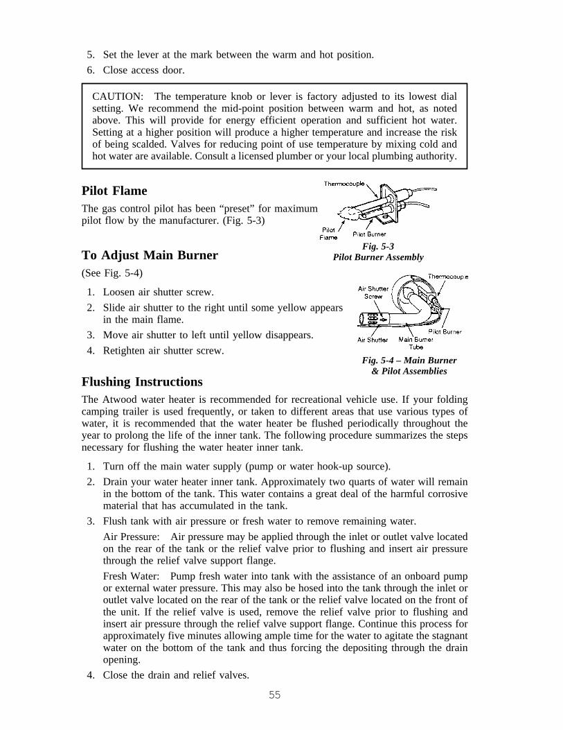
55
5. Set the lever at the mark between the warm and hot position.6. Close access door.
CAUTION: The temperature knob or lever is factory adjusted to its lowest dialsetting. We recommend the mid-point position between warm and hot, as notedabove. This will provide for energy efficient operation and sufficient hot water.Setting at a higher position will produce a higher temperature and increase the riskof being scalded. Valves for reducing point of use temperature by mixing cold andhot water are available. Consult a licensed plumber or your local plumbing authority.
Pilot FlameThe gas control pilot has been “preset” for maximumpilot flow by the manufacturer. (Fig. 5-3)
To Adjust Main Burner(See Fig. 5-4)
1. Loosen air shutter screw.2. Slide air shutter to the right until some yellow appears
in the main flame.3. Move air shutter to left until yellow disappears.4. Retighten air shutter screw.
Flushing InstructionsThe Atwood water heater is recommended for recreational vehicle use. If your foldingcamping trailer is used frequently, or taken to different areas that use various types ofwater, it is recommended that the water heater be flushed periodically throughout theyear to prolong the life of the inner tank. The following procedure summarizes the stepsnecessary for flushing the water heater inner tank.
1. Turn off the main water supply (pump or water hook-up source).2. Drain your water heater inner tank. Approximately two quarts of water will remain
in the bottom of the tank. This water contains a great deal of the harmful corrosivematerial that has accumulated in the tank.
3. Flush tank with air pressure or fresh water to remove remaining water.Air Pressure: Air pressure may be applied through the inlet or outlet valve locatedon the rear of the tank or the relief valve prior to flushing and insert air pressurethrough the relief valve support flange.Fresh Water: Pump fresh water into tank with the assistance of an onboard pumpor external water pressure. This may also be hosed into the tank through the inlet oroutlet valve located on the rear of the tank or the relief valve located on the front ofthe unit. If the relief valve is used, remove the relief valve prior to flushing andinsert air pressure through the relief valve support flange. Continue this process forapproximately five minutes allowing ample time for the water to agitate the stagnantwater on the bottom of the tank and thus forcing the depositing through the drainopening.
4. Close the drain and relief valves.
Fig. 5-4 – Main Burner& Pilot Assemblies
Fig. 5-3Pilot Burner Assembly

56
REFRIGERATOR (Optional)The refrigerator is available for your folding camping trailer as a convenience option.Unlike your home refrigerator, the RV refrigerator can be powered by one of threesources: 120 volt AC, 12 volt DC or LP gas. Another difference from your homerefrigerator is the ability to withstand the many rigors of the road. This includes the day-in and day-out physical punishment, exposure to outside elements like dust, and dramaticchanges in temperature.
For top performance of your RV refrigerator, it is important to make sure the trailer islevel. When the folding camping trailer is parked, proper positioning to level therefrigerator will happen naturally when the trailer is leveled for comfort with nonoticeable sloping of the floor or walls. When the vehicle is moving, the leveling is notcritical because of the rolling and pitching movement.
Another important requirement to keep your refrigerator at optimum performance, is theventilation. The lower vent panel is hinged for access to the controls. The upper vent isfor expelling hot air and gases from the LP burner. These can NOT be altered orrestricted in any way.
Points to Remember• From time to time, especially if the refrigerator has been out of use for a period, make
sure all air vents are free from obstructions before starting up. Also, check connectionsfor gas leaks using an approved commercial test leak solution.
• Never cover or partially cover the air vents with cardboard or anything else.• Remember to level the vehicle when stopping for more than about an hour, otherwise
the cooling unit could be permanently damaged due to overheating if it is left on.• If possible, start the refrigerator on gas some hours before it is to be used to allow time
for the interior to cool. It is then preferable to load the refrigerator with food which hasbeen pre-cooled in your household refrigerator, or at the market.
• Before moving the vehicle, make sure that all containers are tightly covered to avoidspills. If required, crumpled paper may be packed between bottles and other items toprevent shifting while under way.
• Engage the travel catch at the top of the front corner of the door before moving off.
Operation - N260
CONTROLSThe thermostat (1) changes theamount of LP gas that goes to theburner. This acts as the tempera-ture control of the refrigerator.Number 5 is the coldest tempera-ture setting.
NOTE: This is not an automaticgas control. It does not change theflame from high fire to low fire asdo some RV refrigerators. If thecooling load changes, you mustmanually change the gas control to maintain the same temperature inside the refrigerator.

57
When the outside air temperature is less than 50° F, the refrigerator may have a tendencyto freeze food at the colder temperature settings. To reduce the tendency to freeze food:
• Turn the thermostat to a warmer temperature setting.• Keep the refrigerator full.• Put foods that are more likely to freeze on the upper shelf.The selector switch (2) changes the energy source of the refrigerator between LP gas,AC electric, and DC electric and shuts down the refrigerator at the OFF position.
The gas safety valve (3) is built into the control panel. As long as a flame is present, thevalve is open and allows LP gas to flow into the burner. Any loss of flame (empty LP gastank, blow out, etc.) closes and stops the flow of LP gas.
The igniter (4) makes a spark which ignites the flame in the burner.
IGNITION – LP GAS OPERATION1. Open the valve at the LP gas storage tank.2. Turn the thermostat to the coldest temperature setting.3. Turn the selector switch to the LP gas position.4. Push and hold in the safety valve (see WARNING below) and in rapid succession,
push in the igniter several times for about five seconds.• Open the burner box door and look for the flame.• When the flame ignites, release the safety valve.• If the flame does not ignite, wait about five minutes and do this step again.
WARNING: Do not hold in the safety valve for more than 30 seconds. Ifthere is no flame in this time, wait at least two minutes before you try ignitionagain. If you continue to hold in the safety valve, gas will collect and result indangerous personal injury or death.
5. Turn the thermostat to the temperature setting that you wish.
START UP – AC OPERATION• Make sure that 120-volts AC is available.• Turn the selector switch to the AC position.• Turn the thermostat to the temperature setting that you wish.
START UP – DC OPERATION (3-WAY MODELS ONLY)• Make sure that 12-volts DC is available.• Turn the selector switch to the DC position.• Turn the thermostat to the temperature setting that you wish.
SHUT DOWN• Turn the selector switch to the OFF position.• Turn the thermostat to the 1 position.

58
BATTERY DRAIN• In AC operation, there is no battery drain.• In DC operation, the refrigerator draws 12 – 14 amps at 10.5 – 15.4 volts.• If the battery charging stops during DC operation, change the refrigerator to LP gas or
AC until the battery charging starts again.• Check the voltage when in DC operation. The voltage should never drop below
10.5-volts.
ADDITIONAL INFORMATION ON CONTROLSBe attentive when the outer coach surface is being washed down, particularly whenusing power sprays, to avoid wetting electrical controls.
CAUTION: Never allow water to be sprayed on electrical controls located behindthe inlet vent door. Electrical damage or fires could result.
BBQ GRILL (Option)WARNING: The maximum weight limit for the bracket on the side of yourfolding camping trailer is 50 lbs. This limit includes the weight placed on thecarryout stove and the BBQ grill. Exceeding this weight could cause damageto the unit and possibly cause personal injury from hot equipment.
An option for your folding camping trailer is a BBQ Grill. This grill is for use outside ofthe folding camping trailer and comes with a bracket to attach to the side of the unit. Thefollowing list will supply basic operations for the grill. Be sure to read all instructionsincluded with the grill.
1. Install the grill bracket on the side of the folding camping trailer mounting bracket.Make sure that it is securely in place.
2. Place the BBQ grill into the bracket. (Fig. 5-2)
3. Attach the fuel hose to the grill and the LP gas connection located under the foldingcamping trailer by using the “Quick-Coupler” instruction as follows (Fig. 5-3):• Place the handle in the “OFF” position and push back the sleeve. Valve handle
must be in the “OFF” position to make the connection. (Fig. 5-4)• Insert the plug and release the sleeve. (Fig. 5-4)
Fig. 5-2 Fig. 5-3
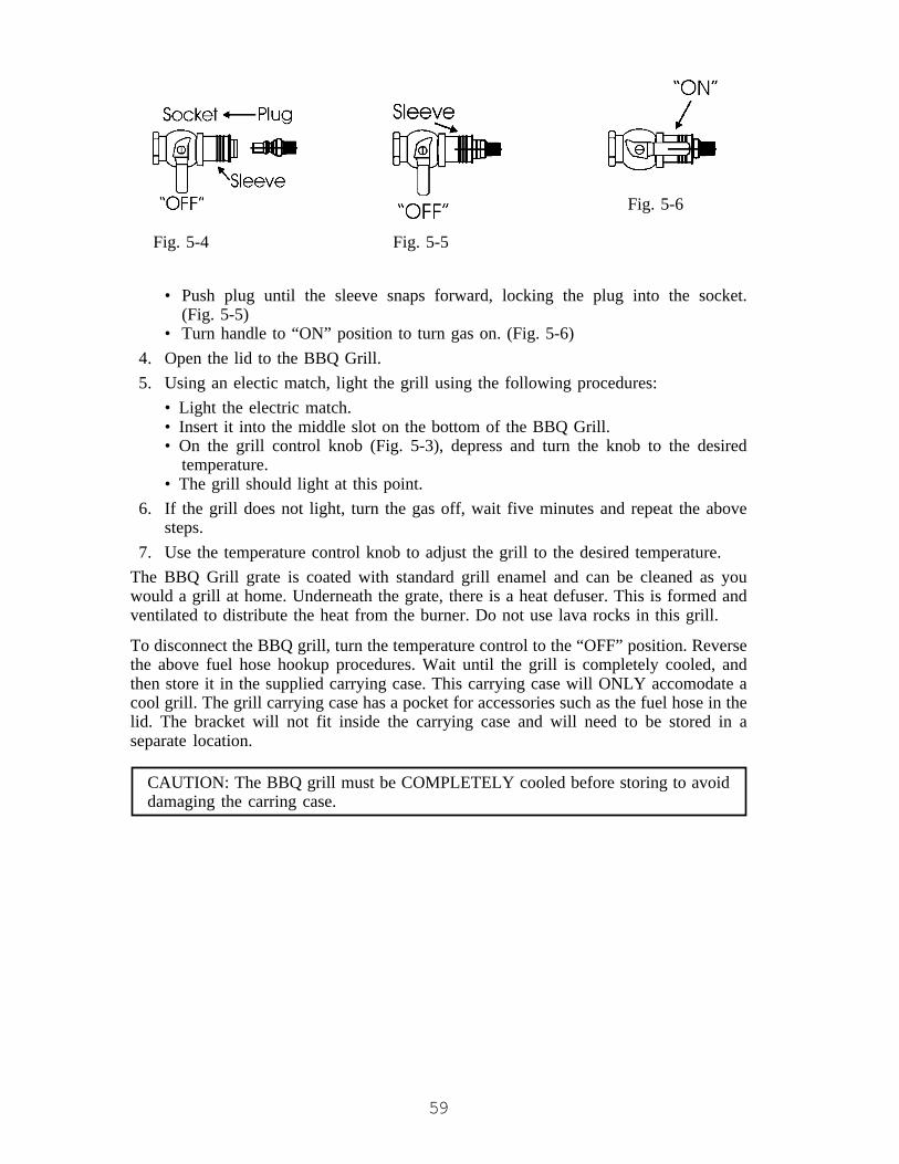
59
• Push plug until the sleeve snaps forward, locking the plug into the socket.(Fig. 5-5)
• Turn handle to “ON” position to turn gas on. (Fig. 5-6)4. Open the lid to the BBQ Grill.5. Using an electic match, light the grill using the following procedures:
• Light the electric match.• Insert it into the middle slot on the bottom of the BBQ Grill.• On the grill control knob (Fig. 5-3), depress and turn the knob to the desired
temperature.• The grill should light at this point.
6. If the grill does not light, turn the gas off, wait five minutes and repeat the abovesteps.
7. Use the temperature control knob to adjust the grill to the desired temperature.The BBQ Grill grate is coated with standard grill enamel and can be cleaned as youwould a grill at home. Underneath the grate, there is a heat defuser. This is formed andventilated to distribute the heat from the burner. Do not use lava rocks in this grill.
To disconnect the BBQ grill, turn the temperature control to the “OFF” position. Reversethe above fuel hose hookup procedures. Wait until the grill is completely cooled, andthen store it in the supplied carrying case. This carrying case will ONLY accomodate acool grill. The grill carrying case has a pocket for accessories such as the fuel hose in thelid. The bracket will not fit inside the carrying case and will need to be stored in aseparate location.
CAUTION: The BBQ grill must be COMPLETELY cooled before storing to avoiddamaging the carring case.
Fig. 5-6
Fig. 5-4 Fig. 5-5
60
CHAPTER 6CARE OF BODY COMPONENTS
EXTERIORAluminumThe aluminum on the outside of your Jayco can be cleaned and washed the same as anautomobile finish. It is suggested that a spray wax or wash and wax combination be usedfor waxing due to the texture of the aluminum. The textured aluminum sifing will reduceexcess scratching. The roof aluminum skin material should be washed and polished tomaintain its finish.
CAUTION: We recommend that you DO NOT take your recreation vehicle throughautomatic car washes and extreme caution should be used if utilizing any type ofpressure sprayer around all attachments, doors, windows, appliance vents, etc. toavoid forcing water inside the unit, possibly damaging components.
Roof
CAUTION: all roofs require maintenance. At least two times each year inspect forcracks, voids, peeling or loose seal and reseal as necessary all seams includingmoldings, vents, doors and windows. (Fig. 6-1)
Weather elements, such as winter’s freezing and summer’s UV rays cause sealants to dryout, shrink, and deteriorate. Contact your dealer for the appropriate sealant to use. Twoareas on your roof require maintenance to be performed to meet warranty coverage onthe folding camping trailer roof.
1. Any corner or center flat trim has putty sealer tape between the metal and the skin.This sealant must be examined and maintained yearly to avoid dry out and cracking.In addition, the roof center flat trim is cap sealed on each end at the front and back.The cap seal should be inspected for cracks, voids, peeling or loose seal two timeseach year and resealed as necessary.To cap seal:• Purchase a sealant as recommended by your dealer.• Remove any excess, cracked, peeling or lifting sealant from around the trim.• Clean the surface before resealing.• Apply a bead of sealant along each side of the trim with a caulking gun.• Using a soapy solution on your index finger, smooth out the sealant along each
side of the trim.2. The trim on the lower edge of the roof is sealed internally and also has an outer cap
seal. If the cap seal becomes loose, separates, or cracks, it must be resealed asindicated on Step #2.
3. Do not add roof attachments (such as boat or bike racks, air conditioners, vents,etc.) in areas not designed to support such accessories. You must maintain the sealaround all after market installed accessories at the attachment points as well.Check all fasteners and accessories on the unit periodically and tighten and seal asneeded. Only factory installed equipment is covered under the terms of the JaycoLimited Warranty.

61
Fig. 6-1
NOTE: It is important to examine all seams and repair them to prevent waterleakage. If you are uncertain about the process to follow, contact your Jaycodealer for assistance.
FrameThe frame on your new Jayco coach has an E-coat paint. It is recommended youperiodically inspect the exterior exposed areas, clean and repaint the steel members toinsure long life. Road debris will chip paint, inviting rust and other deterioration. Toprevent rust or corrosion, you may wish to purchase a commercially available rusttreatment application such as Ziebart, etc. If damage would occur, the frame needs topainted with e-coat paint and not a gloss black paint. This type of paint is available in aspray can from the vendor, Leland.
Tire Covers - Vinyl (Option)To minimize the possibility of the tire “bleeding” through onto the tire cover, werecommend use of a separator (garbage bag, paper, cloth, etc.) between the tire and thetire cover.

62
INTERIOR CARECountertopsMade of high pressure laminate, the countertops are quite easy to keep clean. Glassrings, food spills, water spots and smudges usually wipe off with a damp sponge.Stubborn stains can be removed with a general purpose spray cleaner.
The laminated surface resists alcohol, fruit acids, cosmetics and most household chemi-cals. Avoid contact with dyes, strong laundry bleaches and bluing. Indelible inks used onfood packages may stain, so take care when unpacking groceries, particularly on a dampcountertop. Sharp knives may damage the finish thus confine slicing to a cutting board.
Hot pots and pans should be placed on hot pads or protective trivets. Never place a hotiron or lighted cigarettes on the countertop.
For lasting beauty, avoid using harsh abrasives, scouring powders, peroxide or bleaches.These may dull the surface thus making it more susceptible to staining.
Hardware and Sink or Shower FixturesUse mild dish soap and water to clean these fixtures. Never use harsh chemicals orsprays, such as Windex or Pledge. A mild solution of vinegar and water works very wellto remove hard water spots and stains from sink or shower fixtures.
PANELINGThe wall paneling is a vinyl covered wood panel. If deep scratches occur, they may becovered by using a thin film of shoe polish or stain, followed by a coating of furniturewax. Putty sticks are also available to cover scratches at your local hardware store
To clean, use a mild solution of soap and lukewarm water with a soft sponge or cloth.Refrain from the use of abrasive cleaners as they may scratch and dull appearance.Grease spots and stubborn dirt can be cleaned off with an all-purpose spray cleaner.
FLOORTo care for the decorative no wax vinyl floor covering, wash with a mild detergent.Avoid excessive application of water on new floor as it may cause lifting and curling ofthe vinyl.
63
FABRIC COMPONENTSYour folding camping trailer is a combination of several fabric components used toenclose the living area. The canvas used to construct the bunk end and side panels ismade of 10.10 ounce army duck cotton, treated to pass the required Federal FireRetardant Standards. The folding camping trailer awning (refer to awning definition) ismade of an embossed vinyl with textile backing. On the interior of the folding campingtrailer tent, the material is a 100% polyester backing. The following definitions willassist you in providing the proper care for your folding camping trailer tent components.
DefinitionsINTERIOR1. Bed mat - Upholstery covered foam mattress which provides softness to the bed
extensions.2. Cushions - Upholstery covered foam pad used in dinette area for your comfort.3. Upholstery - Fabric used to cover the interior cushions and bed mats of the folding
camping trailer.4. SoftShades™ - Window covers with a valance used to help create privacy for your
camping experience.5. Privacy Curtains - Fabric panels provided between bed extensions and the folding
camping trailer area to provide a “bedroom” area.6. SofStor™ Components - An option with some folding camping trailers are compo-
nents made of vinyl which provide added gallery cabinets, wardrobe and personalstorage.
EXTERIOR7. Awning - Top or “roof” part of the folding camping trailer tent that is located over
the bed extensions.8. Window Panels – Side and end panels of the folding camping trailer which are
made of canvas or charcoal vinyl with a zip down section to provide light andventilation through an attached “screen” panel.
9. Tent - Complete assembly of the folding camping trailer “soft” wall and roof areas.The tent is made up of the awning and the window panels.
10. Canopy - Added feature to create a shaded area around your folding camping trailerdoor for outside enjoyment.
11. Screen Room - Available feature to enhance the canopy area by providing an added“room” to your folding camping trailer. This “room” is attached to the canopy andthe camper.

64
FABRIC CARECushions/Bed MatsPlease use common sense and treat your furniture as you would at home. Remember,your folding damping trailer is a small living area, so soiling may occur more frequentlyand the fabric will probably need more attention than your furniture at home. Pleasefollow these guidelines for cleaning upholstery fabrics on the cushions/bed mats.
Frequent vacuuming with a brush attachment or a light hand brushing will help removedust, hair, sand and other particles which may dull the look of the fabric and acceleratewear.
Water base cleaners are recommended. If a spill does occur, blot up the spot, but do notrub it in. Solvents are not recommended since they may have an adverse reaction to thespecific backing of your upholstery fabric. Do not saturate the area. Clean in a wellventilated area and avoid products containing toxic materials. Always pre-test a smallarea before proceeding. Use a professional furniture cleaning service for an overallcleaning.
A reminder: The upholstery fabrics have been manufactured using quality materials.However, if abused, they are not completely resistant to damage.
CAUTION: Do not dry clean the covers of the cushions/bed mats. If the covers aredry cleaned, the vinyl will become hard and crack.
SoftShades™SoftShades™ should be dry cleaned by a professional for best results. However, theymay be washed in cool water on the delicate cycle. Line dry only.
CAUTION: Care must be taken to follow above instructions or results may not besatisfactory.
NapSak™Dry clean only.
TentsProper care and maintenance are important for the life of your folding camping trailer’stent. We recommend the following list of suggestions be adhered to when there is a needto clean the tents.
Exterior• If the tent becomes dirty, use a damp cloth or sponge with water. Do not use harsh
detergents, soaps or solvents since they may remove water repellency, fire retardants,and damage the surface or color.
• Do not use aerosol type cleaners.
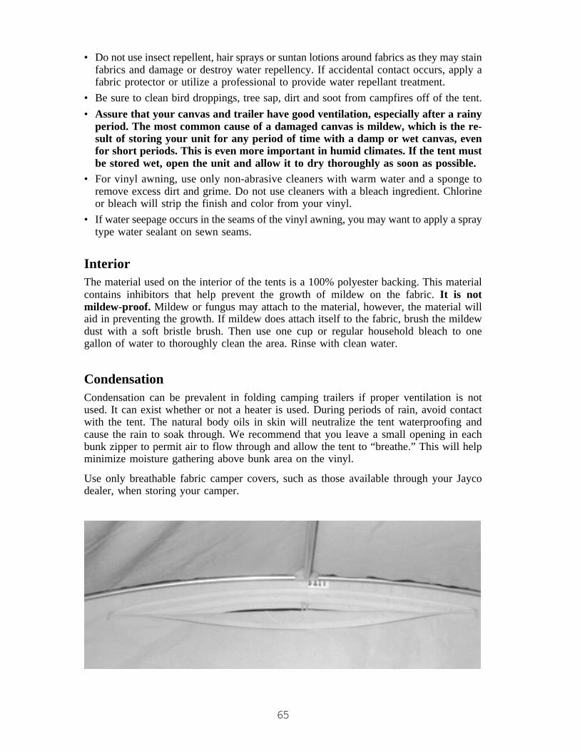
65
• Do not use insect repellent, hair sprays or suntan lotions around fabrics as they may stainfabrics and damage or destroy water repellency. If accidental contact occurs, apply afabric protector or utilize a professional to provide water repellant treatment.
• Be sure to clean bird droppings, tree sap, dirt and soot from campfires off of the tent.• Assure that your canvas and trailer have good ventilation, especially after a rainy
period. The most common cause of a damaged canvas is mildew, which is the re-sult of storing your unit for any period of time with a damp or wet canvas, evenfor short periods. This is even more important in humid climates. If the tent mustbe stored wet, open the unit and allow it to dry thoroughly as soon as possible.
• For vinyl awning, use only non-abrasive cleaners with warm water and a sponge toremove excess dirt and grime. Do not use cleaners with a bleach ingredient. Chlorineor bleach will strip the finish and color from your vinyl.
• If water seepage occurs in the seams of the vinyl awning, you may want to apply a spraytype water sealant on sewn seams.
InteriorThe material used on the interior of the tents is a 100% polyester backing. This materialcontains inhibitors that help prevent the growth of mildew on the fabric. It is notmildew-proof. Mildew or fungus may attach to the material, however, the material willaid in preventing the growth. If mildew does attach itself to the fabric, brush the mildewdust with a soft bristle brush. Then use one cup or regular household bleach to onegallon of water to thoroughly clean the area. Rinse with clean water.
CondensationCondensation can be prevalent in folding camping trailers if proper ventilation is notused. It can exist whether or not a heater is used. During periods of rain, avoid contactwith the tent. The natural body oils in skin will neutralize the tent waterproofing andcause the rain to soak through. We recommend that you leave a small opening in eachbunk zipper to permit air to flow through and allow the tent to “breathe.” This will helpminimize moisture gathering above bunk area on the vinyl.
Use only breathable fabric camper covers, such as those available through your Jaycodealer, when storing your camper.
66
CanopyHeavy rain can damage both the canopy fabric and the poles if it is allowed to “pocket”on the fabric. It is very important to have the correct slope in the canopy. The side of thecanopy at the twist poles should be about 19" lower than the side that attached to theawning rail on the roof. If heavy rain is anticipated, lower one side to allow adequate runoff.
The canopy is to be removed for winter storage due to winter condensation accumula-tion. ALWAYS roll up your canopy dry. Should you ever need to roll up canopy when itis wet, unroll within 24 hours and allow to dry. Mildew will develop on damp and wetcanopies.
Be sure to follow the list of Do’s and Don’ts below when caring for your canopy.
Some Do’s:DO• Keep your canopy clean. This is the
best protection against mildew.Even on mildew resistant fabricmildew can grow on accumulateddirt or foreign materials whichremain on the top or bottom surfaceand eventually damage or stain thefabric. We cannot be responsiblefor such damage.
• Wash down your canopy; brushinglightly with a cloth or soft brush.
• Hose your canopy downoccasionally (every month) with agarden hose. We recommend doingthis on a hot, sunny day.
• Keep the underside of your canopyclean by simply brushing with aclean household broom. Theunderside can be washed in thesame manner as the top.
• Keep shrubbery and vines awayfrom the canopy, as many bushescontain acid which can be harmful.
Some Don’ts:DO NOT• Fold or roll in extreme cold
temperatures.• Drag your canopy across any
abrasive surfaces, such as a cementdrive.
• Get insect spray on the fabric, assome solutions may impair thewater repellency of the fabric andcause staining.
• Allow water to stand on thecanopy, causing pocketing andpossible stretching.
• Wash your canopy with a harsh orstrong solution, or scrub toovigorously with an abrasive cleaner.
• Force or yank your canopy whenraising or lowering it. Do itgradually.
• Charcoal grill underneath thecanopy.
• Store the canopy when damp orwet. Mildew is a fabric’s greatestenemy and is caused by dampness.Mildew may grow on the surface ofa damp canopy and permanentlystain the fabric.
• Permit leaves, twigs, etc. to remainon your canopy as they might causea staining of the fabric.
• Wrap steel or aluminum hardwarewith the canopy.
67
Screen RoomCare should be taken when setting up and putting screen room away to avoid tears andcuts. When putting away the deluxe screen room, the curtains should be in the downposition and secured to the bottom with their strings.
1. Wash off any droppings or foreign matter from the trees with clear water and keepvinyl clean when putting away.
2. Do not roll stakes or hardware with the screen room.3. Never roll vinyl screen room up wet for any extended period of time.4. If mildew is apparent, it should be treated promptly with a light solution of Naphtha
soap and water. A soft brush or cloth is recommended for cleaning vinyl.
Fiberglass ScreeningWhen possible, fiberglass screening should be loosely folded, not crushed when openingand putting away screen room. Do not allow poles and stakes to punch holes in thescreen.
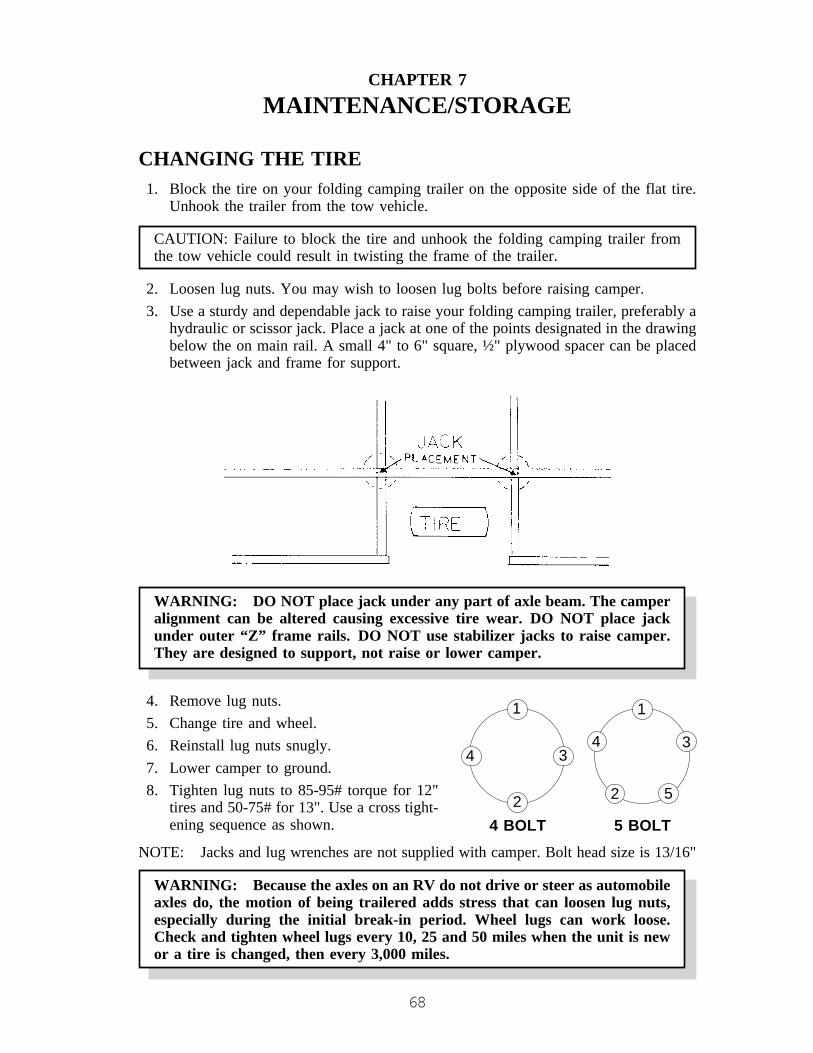
68
CHAPTER 7MAINTENANCE/STORAGE
CHANGING THE TIRE1. Block the tire on your folding camping trailer on the opposite side of the flat tire.
Unhook the trailer from the tow vehicle.
CAUTION: Failure to block the tire and unhook the folding camping trailer fromthe tow vehicle could result in twisting the frame of the trailer.
2. Loosen lug nuts. You may wish to loosen lug bolts before raising camper.3. Use a sturdy and dependable jack to raise your folding camping trailer, preferably a
hydraulic or scissor jack. Place a jack at one of the points designated in the drawingbelow the on main rail. A small 4" to 6" square, ½" plywood spacer can be placedbetween jack and frame for support.
WARNING: DO NOT place jack under any part of axle beam. The camperalignment can be altered causing excessive tire wear. DO NOT place jackunder outer “Z” frame rails. DO NOT use stabilizer jacks to raise camper.They are designed to support, not raise or lower camper.
4. Remove lug nuts.5. Change tire and wheel.6. Reinstall lug nuts snugly.7. Lower camper to ground.8. Tighten lug nuts to 85-95# torque for 12"
tires and 50-75# for 13". Use a cross tight-ening sequence as shown.
NOTE: Jacks and lug wrenches are not supplied with camper. Bolt head size is 13/16"
WARNING: Because the axles on an RV do not drive or steer as automobileaxles do, the motion of being trailered adds stress that can loosen lug nuts,especially during the initial break-in period. Wheel lugs can work loose.Check and tighten wheel lugs every 10, 25 and 50 miles when the unit is newor a tire is changed, then every 3,000 miles.
1
2
34
5
1
2
34
4 BOLT 5 BOLT
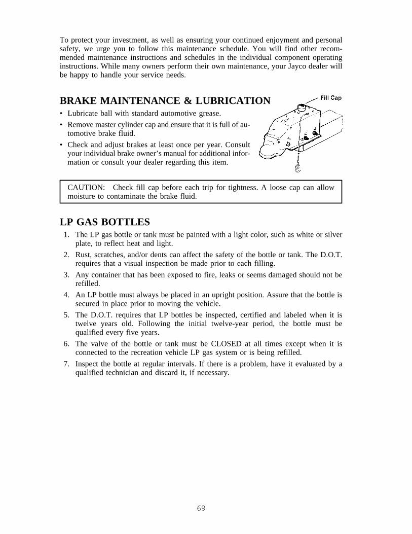
69
To protect your investment, as well as ensuring your continued enjoyment and personalsafety, we urge you to follow this maintenance schedule. You will find other recom-mended maintenance instructions and schedules in the individual component operatinginstructions. While many owners perform their own maintenance, your Jayco dealer willbe happy to handle your service needs.
BRAKE MAINTENANCE & LUBRICATION• Lubricate ball with standard automotive grease.• Remove master cylinder cap and ensure that it is full of au-
tomotive brake fluid.• Check and adjust brakes at least once per year. Consult
your individual brake owner’s manual for additional infor-mation or consult your dealer regarding this item.
CAUTION: Check fill cap before each trip for tightness. A loose cap can allowmoisture to contaminate the brake fluid.
LP GAS BOTTLES1. The LP gas bottle or tank must be painted with a light color, such as white or silver
plate, to reflect heat and light.2. Rust, scratches, and/or dents can affect the safety of the bottle or tank. The D.O.T.
requires that a visual inspection be made prior to each filling.3. Any container that has been exposed to fire, leaks or seems damaged should not be
refilled.4. An LP bottle must always be placed in an upright position. Assure that the bottle is
secured in place prior to moving the vehicle.5. The D.O.T. requires that LP bottles be inspected, certified and labeled when it is
twelve years old. Following the initial twelve-year period, the bottle must bequalified every five years.
6. The valve of the bottle or tank must be CLOSED at all times except when it isconnected to the recreation vehicle LP gas system or is being refilled.
7. Inspect the bottle at regular intervals. If there is a problem, have it evaluated by aqualified technician and discard it, if necessary.

70
STORAGEDepending upon your area and where your unit is stored, your camper may be a targetfor damage from rodents and insects. To protect your camper, never leave food insidethe unit and ensure that all surfaces are clean. You may want to place rodent controlproducts in the unit during periods of storage. Mice can do a tremendous amount ofdamage to the tent, drapes, cushions, etc. particularly during the winter months. Storingunits in fields make them particularly inviting to rodents. Periodically inspect your unitduring storage and seal off any areas which can offer an entry point to rodents or insects.Please remember to remove any screens or tape you have used to seal openings beforeyou use the camper again. Special interest publications, such as articles and booksoffered through TL Enterprises (Trailer Life, Motorhome, etc.) can offer additional andpractical advice on the proper storage of your camper. Damage from rodents or insectsare NOT covered under your Jayco Limited Warranty.
CAUTION: DO NOT store camper under a dark colored cover. Use only lightcolored, breathable covers to prevent extreme heat. Consult your Jayco dealer forthe proper products to use.
CAUTION: When storing your folding camping trailer, it is recommended that thebattery be unhooked to avoid draining the battery.

71
MAINTENANCE CHARTCOMPONENT MAINTENANCE AVOID
(a.) Exposure to water orcondensation will causebearings to rust.
(b.) Never let bearings rundry.
(c.) Never overpack wheelbearings, especially inthe middle of hub. It willtrap heat if overpacked.
The wheel bearings in yournew Jayco tent camper arepre-greased. It is recom-mended that you repack thesebearings at 12,000 miles or atthe end of each season’scamping to prepare for win-ter months ahead.
Use only a multipurpose No.1 or 2 good quality wheelbearing grease.
If bearing or cone (race)become pitted, replace anydamaged part.
NOTE: Should you beconcerned about heat in wheelbearings, check themoccasionally while travelingby placing hand on hub. Youwill be able to hold your handmomentarily on the hub.
Should it be extremely hot, itis recommended to have thebearings inspected by aqualified service center.
NOTE: During break-inperiod (first 500 miles) yourhubs may feel extra warm dueto brake shoes setting in withthe brake drum.
Wheel Bearings
Lug nuts must be checked at10, 25, and 50 miles when newor after tire removal, then every3,000 miles. After this, lug nutsshould be periodically checkedfor safety, especially beforeany long trip and extensivebraking or a tire change.
Tighten lug nuts to specifiedtorque using a cross tightensequence.
See “Changing the Tire &Wheel” section of Chapter 7.
WARNING:DO NOT ignore checkingwheel lug nuts. Failure to docan cause wheel loss and anaccident.
Lug Nuts

72
Coupler
Tongue Jack
Use a small quantity ofWD-40 on moving mechanismand all points of movement inactuator to insure ease of op-eration.
We recommend that you useconventional grease on the ballof hitch for ease of operation.
COMPONENT MAINTENANCE AVOID
Lubricate the jack by extend-ing to full down position andinsert SAE 30 oil through oilhole in top of jack. Do thisseveral times per season.
It is very important to checktires often as noted in Chapter3.
Tires DO NOT ignore checking tireP.S.I. pressures often. Alwayscheck tire pressure duringtravel & before each trip.
It is important to have brakesadjusted by selling dealer at200 miles after initial break-in period. This operation maynot be included by sellingdealer as part of selling price.
After initial break-in it is rec-ommended to adjust the brakesfollowing each 3,000 miles orat beginning of each season’scamping trips.
Brakes It is very important to keepbrakes adjusted as poorly ad-justed brakes will not func-tion correctly and cause ac-celerated wear.
Check cap for tightness be-fore each trip. Make sure cyl-inder is at full mark. Use Dot3 automotive brake fluid.
Master Cylinder
DO NOT use grease or oil onposts as this lubricant willattract dirt and cause tent tobecome dirty.
Lifter Posts Your telescoping posts shouldbe lubricated semi-annuallywith a light coat of siliconespray to insure smooth,trouble-free operation. Do notpermit spray to reach tent.

73
Bed Braces Inspect and replace if bent ordamaged.
Using damaged bed braces.
COMPONENT MAINTENANCE AVOID
Winch
Cables
LP Gas System
Bed Slides
DO NOT smoke while chang-ing bottles or any lines.
DO NOT allow any connec-tion to be loose.
DO NOT use ammonia basedcleaners.
The winch should be lubri-cated once per year, prefer-ably at the season’s begin-ning. Use a small quantity oflight oil on two upper shaftbearings and also at each endof main drum which cablerolls on.
Pulleys and cables need nolubricant at any time.
At the beginning of eachseason:
1. Inspect all gas lines forcrimps and road damage.
2. Check all lines and con-nections for leakage withsoapy water or leak detec-tor.
3. We recommend that youhave the regulator checkedand adjusted to proper pres-sure once a year. A gasleak check should be per-formed at least once a yearby a qualified technician.
Be sure to lubricate bed slidestwice per year with siliconespray as you do the lifter posts.
Frame Inspect, clean and repaint steelmembers.
Apply a commercial rust treat-ment.

74
To care for brushed chromewe recommend you clean witha mild soap and water, wipedry with soft cloth. Apply alight coat of oil such as“Johnson’s Baby Oil” peri-odically.
Various items on theseappliances need to be cleanedperiodically, such as burnerorifices, etc. See individualbooklets for directions or seeyour dealer.
On any appliance with porce-lain covering, use caution toavoid chipping. Be careful notto drop items on porcelainsurfaces.
COMPONENT MAINTENANCE AVOID
Appliances DO NOT use steel wool, am-monia, acids, or abrasives onchrome surfaces.
Roof Excessive snow and ice loads.All roofs require maintenance.At least two times each year,inspect all seams: front, rearand along all moldings forvoids, lifting, peeling or crack-ing. Reseal as necessary or atleast one time each year. Ifyou notice any deteriorationin the seal, scrape off anycracked or loose sealant andthen reseal the area.
Roof Latches Inspect for tightness and dam-age. Periodically adjust tomaintain tension and replacewhen damaged.

75
COMPONENT MAINTENANCE AVOID
Exterior Sealants All sealants used in construc-tion can deteriorate from U.V.exposure, air pollution, freez-ing temperatures and otherexposure to weather elements.
Tape sealants used arounddoors, sidewall mounted fix-tures and extrusions are sub-ject to dry-out conditions bysunlight and will allow waterseepage when they deterio-rate.
Inspect at least two times eachyear and look for dried-out,cracking or peeling condi-tions. Reseal as necessary orat least one time each year.Contact your dealer for theappropriate sealant to use.
Using poor quality sealingmaterial.
Failure to reseal sealant andputty tape.
76
MAINTENANCE CHECKLISTPrior to First Trip
� Install SofStor® organizer (SofStor® organizer option only).� Install privacy drapes. (Privacy drape option only.)� Condition the tent.� Check LP gas lines for leaks.� Test LP gas detector.� Sanitize fresh water system.� Tighten wheel nuts to specified torque values.� Open all windows and the door and start the furnace. Leave the windows and
door open and the furnace on until all fumes fully dissipate. (Furnace optiononly.)
First Ten Miles� Tighten wheel nuts to specified torque values.
First Twenty-Five Miles� Tighten wheel nuts to specified torque values.
First Fifty Miles� Tighten wheel nuts to specified torque values.
First Two-Hundred Miles� Tighten wheel nuts to specified torque values.� Have brakes adjusted by a qualified service technician.
Each Trip� Test LP gas detector.� Inspect bed bow supports� Check battery water level. (If equipped with battery.)� Check brake fluid level in master cylinder reservoir. Keep filled to within ½”
from top of reservoir. (Hydraulic Brake option only.)� Check master cylinder cap for tightness. (Hydraulic Brake option only.)� Check tire pressure and wear.� Check running lights.� Inspect safety chains for signs of wear.� Test brakes.
After Every Tire Change� Tighten wheel nuts to specified torque values at ten miles, twenty-five miles
and fifty miles.

77
Daily� Recharge battery after each use. (If equipped with battery.)� Ensure LP gas detector operation light is green in color.
Weekly� Test LP gas detector.� Check tire pressure and wear.
Monthly� Clean and lubricate the coupler.� Check fire extinguisher pressure. Do not test the extinguisher.� Test the ground fault circuit interrupter (GFCI)
Every Three Months or 3,000 Miles� Vacuum around LP burner and pilot light areas.� Compare water heater pilot flame with ideal flame. Refer to the water heater
owner’s manual for ideal flame. Clean and adjust as necessary. (Deluxeplumbing option only.)
� Compare refrigerator pilot flame with ideal flame. Refer to the refrigeratorowner’s manual for ideal flame. Clean and adjust as necessary. (Refrigeratoroption only.)
� Inspect refrigerator/ice box door seals.� Inspect refrigerator combustion seals. (Refrigerator option only.)� Check LP gas lines for leaks.� Inspect LP cylinders for rust, pits, gouges, scrapes or sharp dents. Repaint
cylinders if rust is present.� Clean and lubricate the large seal and cap seal located on the toilet. (Toilet
option only.)� Clean the ventilation seal on the toilet. (Toilet option only.)� Drain and sanitize fresh water system.� Check, clean, tighten and lubricate battery cables. (If equipped with battery.)� Tighten wheel nuts to specified torque values.� Examine the tires for unusual wear, sidewall defects, cuts, wear, bulging and
abrasions.� Lubricate tongue jack.� Lubricate hitch ball.� Have breaks adjusted by a qualified service technician.� Inspect roof latches for tightness and damage. Adjust to maintain tension and
replace if necessary.
78
Every Four Months or 4,000 Miles� Flush out water heater tanks.
Every Six Months or 6,000 Miles� Clean drains with approved drain cleaners.� Check pipe connections for tightness. Tighten if necessary.� Lubricate lifter posts.� Lubricate bed slides.� Lubricate all moving parts on the entrance steps. (Retractable steps option
only.)� Lubricate entrance and baggage door locks.� Clean and lubricate stabilizer jacks.� Inspect wheels for cracks, dents or distortion.� Inspect and reseal all sealant and putty tape.� Have suspension system serviced by a qualified service technician.
Every Year or 12,000 Miles� Repack wheel bearings.� Lubricate moving parts on the canopy hardware. (Canopy option only.)� Inspect and lubricate gears, reel shaft and handle threads on winch.� Oil drive shaft bearings.� Manually operate the pressure-temperature control lever or dial to the lowest
possible position on the water heater.� Clean city water entry strainer.� Check demand tank vent for obstructions.� Check water pump connections and mountings for tightness.� Vacuum the LP gas detector cover.� Clean absorption refrigerator flue. (Refrigerator option only.)� Have LP gas system inspected and serviced by a qualified technician.� Have the refrigerator inspected and serviced by a qualified technician.� Have brakes inspected and serviced by a qualified technician.� Have furnace inspected and serviced by a qualified technician.
Every Twelve Years� Have your LP gas cylinders inspected, qualified, recorded and stamped by a
certified cylinder qualifier. DOT also requires qualification every five yearsafter the initial twelve year certification.
79
EXTENDED TRANSFERABLE LIMITED WARRANTY
80

81
TOWABLE TRANSFERABLE LIMITED WARRANTY
82
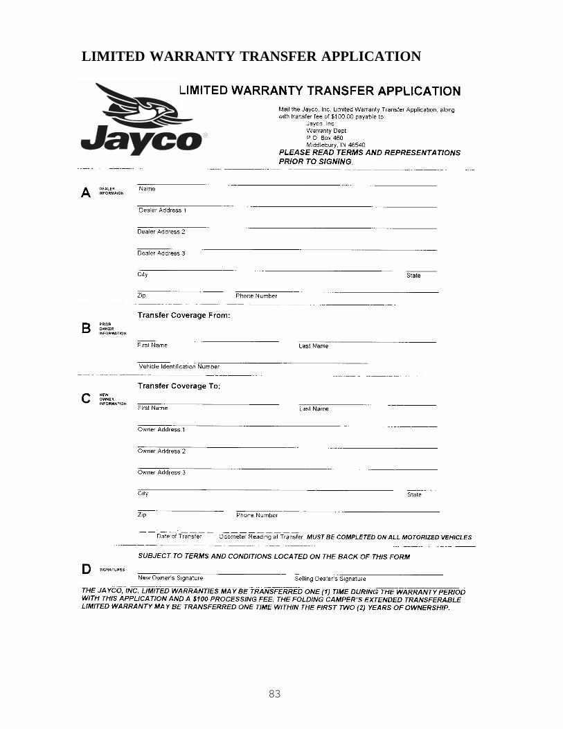
83
LIMITED WARRANTY TRANSFER APPLICATION
84
Terms and RepresentationsBy signing your signature(s) on the face side of this form, and in order toinduce Jayco, Inc. to transfer its Limited Warranty, you represent thefollowing:
1. That you have received and read a copy of the Jayco LimitedWarranty and Owner’s Manual.
2. You understand that the unit is to be used only for recreationalcamping and travel.
3. That all information provided by you on the face side of this form istrue and correct.
4. You understand that you are purchasing a pre-owned recreationalvehicle and Jayco, Inc. does not make any representation as to itspresent condition.

85
NOTES
®
903 South Main Street • P.O. Box 460 • Middlebury, IN 46540
WELCOME TO THE JAYCO FAMILY!As the owner of a new Jayco recreational vehicle we are
proud to welcome you to our growing family.All Jayco RV homes are built with care, under the watchful
eye of our Quality Assurance program. And it is our sincerewish that you will have a lifetime of fun times with your newJayco.
We are pleased you chose Jayco and want to doeverything possible to make sure you stay as happy with yourJayco RV home as you were on the day you bought it.
We work closely with Jayco dealers to provide customerservice for you. We honestly feel that Jayco dealers are onthe whole the best in the business. And with nearly 300 ofthem in the U.S. and Canada you should never be too farfrom help if you ever need it.
In the months and years to come we hope you’llbecome a close member of the Jayco family. Oneway to enjoy your Jayco even more is through ourowners club – the Jafari International Travel Club.It’s lots of fun and a great way to meet othermembers of the Jayco family. If you’re interestedplease talk to your dealer about the “flight” in yourarea. Or write to us directly and we’ll be in touch.
From Jayco’s family to yours: “Welcome Home!”


