127
Where Tradition and Innovation Meet... Mini-Motorhome Owner’s Manual T Y P E C

Where Tradition
and Innovation
Meet...
Mini-Motorhome
Owner’s Manual
TYPE
C

Cunningham Campers, Inc.5201 Highway 62
Jeffersonville, IN 471301-812-284-0276 Option 3
Welcome to our Used Jayco Owners' Group
We Know Jayco Parts! As a group member you receive 10% OFF any order for parts, not already on sale. Just call us with your VIN # and we will find what you need and ship it directly from Jayco to your front door.
Like Jayco, we are family owned and operated. Our courteous professionals are here to help make your shopping experience as pleasant as humanly possible.
1-812-284-0276Use Option 3 For Parts
http://parts.cunninghamcampers.com/jaycoclubCunningham’s – Selling & Servicing Jayco RV’s for OVER 38 Years!
� WARNING: Read all instructions in manual before using your camper.
This manual has been provided by Jayco, Inc. for the sole purpose of providinginstructions concerning the operation and maintenance of this vehicle and itscomponents. Nothing in this manual creates any warranty, either expressed orimplied. The only warranty offered by Jayco, Inc. is as set forth in the limited warrantyapplicable to this vehicle.
The owner’s failure to provide required service and/or maintenance could result in theloss of warranty. The owner should review Jayco’s limited warranty and the limitedwarranties of all other manufacturers offering them that are applicable to this vehicle.
Instructions are included in the manual for operating various components which areoptional on some vehicles. In addition, the owner should refer to individualmanufacturer’s operating instructions contained in the owner’s packet.
©2001 Jayco, Inc. LITHO U.S.A. 02-1 PART NO. 0053066

YOUR NEW JAYCO IS YOUR PASSPORT TO A WHOLE WORLD OF NEW FRIENDSCAMPING FUN AND TRAVEL ADVENTURE WHEN YOU JOIN THE THOUSANDSOF JAYCO FAMILIES WHO MAKE UP THE . . .
INTERNATIONAL JAYCO JAFARI TRAVEL CLUB
You will find us enjoying the friendship and fellowship of JAFARI CAMPING as we join ourlocal area FLIGHTS at hundreds of weekend camp-outs all over North America eachmonth . . .
WE’RE THE FAMILIES OF JAYCO!
There are special STATE, REGIONAL and INTERNATIONAL RALLIES where you canjoin with your fellow JAFARIANS and their flights to enjoy a special kind of togetherness .. . fun, games, and entertainment provide memories to last a lifetime.
And . . . how about the exotic surroundings of NEW ORLEANS, the sounds and color ofNASHVILLE and the GRAND OLE OPRY, the mystery of MEXICO., the roar and rush ofthe INDIANAPOLIS 500, the quiet surroundings of the CANADIAN ROCKIES, the colorof the SMOKY MOUNTAINS in the Fall. These and many other adventures can be yourswhen you join . . .
THE INTERNATIONAL JAYCO JAFARI TRAVEL CLUB
Fill in the blanks on the reverse side, cut along dotted line and mail along with a check to:
INTERNATIONAL JAYCO JAFARI
P.O. Box 192
Osceola, IN 46561-0192
ATTN: Membership Director
Yes, it’s for everyone with a JAYCO; young couples just starting out, families spending qualitytime together, the young at heart expanding their life experiences. Whether you belong toanother camping club, have always traveled alone, or are just starting, don’t miss out on one ofthe most priceless benefits of being an RV family . . . meet new friends and spend a bit of yourcamping life with some of the finest people you will ever have the opportunity to share acampfire or treasure a moment of golden living with . . Fifth-Wheel Travel Trailer . . .Mini-Motorhome. . . Conventional Travel Trailer . . . Folding Camping Trailer . . . it doesn’tmatter, if you are a JAYCO FAMILY, then you are eligible to become a JAFARI MEMBER.
. . . YOU WILL NEVER BE SORRY YOU MADE THE DECISION
In addition to the special International decals for your unit, distinctive patches, the HITCHnewsletter with schedules of upcoming events and activities, your membership entitles you tothe following special benefits: MEMBERSHIP ROSTER containing the names and addresses ofcurrent members of the club. REGISTERED KEY RING, so if your keys are lost, they can bereturned to the International Office and then returned to you. DISCOUNT CARDS for severalnational theme parks including, Sea World, King’s Dominion, Silver Dollar City,Adventureland Park and Six Flags. DISCOUNT PRICES on Trailer Life and Motorhomecamping magazines. SPECIAL PRICES on Wheeler’s Guide, Woodall’s Campground Directoryand the Rand McNally road atlas. DISCOUNT PRESCRIPTION SERVICE. CAR RENTALDISCOUNTS. PLUS, the joy of meeting new friends and enjoying Jaytrek Adventures aroundthe country. Start with the first phase of your camping life . . just complete the application andforward it to the JAFARI INTERNATIONAL TRAVEL CLUB OFFICE.
WELCOME TO THE JAFARI FAMILY!
TO: Membership Director, International Jayco Jafari
Please enroll us as members in the International ... We’re ready to roll to where the “friends wejust haven’t met yet” have the coffee on the fire and are waiting for us to arrive: We are ...
Name: Spouse:
Address: Phone:
City: State: Zip:
Ages of Children at Home:
Our JAYCO is a: Our Dealer(type & size)
Membership Dues: (One year rate $20.00)
Two years: $35.00 Amount enclosed. $
Three years: $50.00 Check #:
(signature) (date)
�
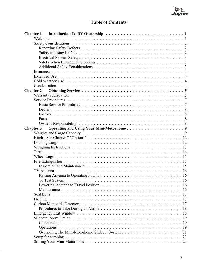
Table of Contents
Chapter 1 Introduction To RV Ownership . . . . . . . . . . . . . . . . . . . . . . . . . . 1
Welcome . . . . . . . . . . . . . . . . . . . . . . . . . . . . . . . . . . . . . . . . . . . . 1Safety Considerations . . . . . . . . . . . . . . . . . . . . . . . . . . . . . . . . . . . . . 2
Reporting Safety Defects . . . . . . . . . . . . . . . . . . . . . . . . . . . . . . . . . . 2Safety in Using LP Gas . . . . . . . . . . . . . . . . . . . . . . . . . . . . . . . . . . . 2Electrical System Safety. . . . . . . . . . . . . . . . . . . . . . . . . . . . . . . . . . . 3Safety When Emergency Stopping . . . . . . . . . . . . . . . . . . . . . . . . . . . . . 3Additional Safety Considerations . . . . . . . . . . . . . . . . . . . . . . . . . . . . . . 3
Insurance . . . . . . . . . . . . . . . . . . . . . . . . . . . . . . . . . . . . . . . . . . . . 4Extended Use . . . . . . . . . . . . . . . . . . . . . . . . . . . . . . . . . . . . . . . . . . 4Cold Weather Use . . . . . . . . . . . . . . . . . . . . . . . . . . . . . . . . . . . . . . . 4Condensation . . . . . . . . . . . . . . . . . . . . . . . . . . . . . . . . . . . . . . . . . . 4
Chapter 2 Obtaining Service . . . . . . . . . . . . . . . . . . . . . . . . . . . . . . . . . . 5
Warranty registration . . . . . . . . . . . . . . . . . . . . . . . . . . . . . . . . . . . . . . 5Service Procedures . . . . . . . . . . . . . . . . . . . . . . . . . . . . . . . . . . . . . . . 7
Basic Service Procedures . . . . . . . . . . . . . . . . . . . . . . . . . . . . . . . . . . 7Dealer . . . . . . . . . . . . . . . . . . . . . . . . . . . . . . . . . . . . . . . . . . . . 8Factory. . . . . . . . . . . . . . . . . . . . . . . . . . . . . . . . . . . . . . . . . . . . 8Parts . . . . . . . . . . . . . . . . . . . . . . . . . . . . . . . . . . . . . . . . . . . . . 8Owner's Responsibility . . . . . . . . . . . . . . . . . . . . . . . . . . . . . . . . . . . 8
Chapter 3 Operating and Using Your Mini-Motorhome . . . . . . . . . . . . . . . . . . . 9
Weights and Cargo Capacity . . . . . . . . . . . . . . . . . . . . . . . . . . . . . . . . . . 9Hitch - See Chapter 7 "Options" . . . . . . . . . . . . . . . . . . . . . . . . . . . . . . . 12Loading Cargo. . . . . . . . . . . . . . . . . . . . . . . . . . . . . . . . . . . . . . . . . 12Weighing Instructions . . . . . . . . . . . . . . . . . . . . . . . . . . . . . . . . . . . . . 13Tires . . . . . . . . . . . . . . . . . . . . . . . . . . . . . . . . . . . . . . . . . . . . . . 14Wheel Lugs . . . . . . . . . . . . . . . . . . . . . . . . . . . . . . . . . . . . . . . . . . 15Fire Extinguisher . . . . . . . . . . . . . . . . . . . . . . . . . . . . . . . . . . . . . . . 15
Inspection and Maintenance . . . . . . . . . . . . . . . . . . . . . . . . . . . . . . . . 15TV Antenna . . . . . . . . . . . . . . . . . . . . . . . . . . . . . . . . . . . . . . . . . . 16
Raising Antenna to Operating Position . . . . . . . . . . . . . . . . . . . . . . . . . . 16To Test System. . . . . . . . . . . . . . . . . . . . . . . . . . . . . . . . . . . . . . . 16Lowering Antenna to Travel Position . . . . . . . . . . . . . . . . . . . . . . . . . . . 16Maintenance . . . . . . . . . . . . . . . . . . . . . . . . . . . . . . . . . . . . . . . . 16
Seat Belts . . . . . . . . . . . . . . . . . . . . . . . . . . . . . . . . . . . . . . . . . . . 17Driving . . . . . . . . . . . . . . . . . . . . . . . . . . . . . . . . . . . . . . . . . . . . 17Carbon Monoxide Detector . . . . . . . . . . . . . . . . . . . . . . . . . . . . . . . . . . 17
Procedures to Take During an Alarm . . . . . . . . . . . . . . . . . . . . . . . . . . . 18Emergency Exit Window . . . . . . . . . . . . . . . . . . . . . . . . . . . . . . . . . . . 18Slideout Room Option . . . . . . . . . . . . . . . . . . . . . . . . . . . . . . . . . . . . 19
Components . . . . . . . . . . . . . . . . . . . . . . . . . . . . . . . . . . . . . . . . 19Operations . . . . . . . . . . . . . . . . . . . . . . . . . . . . . . . . . . . . . . . . . 19Overriding The Mini-Motorhome Slideout System . . . . . . . . . . . . . . . . . . . . 21
Setup for camping . . . . . . . . . . . . . . . . . . . . . . . . . . . . . . . . . . . . . . . 23Storing Your Mini-Motorhome . . . . . . . . . . . . . . . . . . . . . . . . . . . . . . . . 24
i

Chapter 4 The Systems. . . . . . . . . . . . . . . . . . . . . . . . . . . . . . . . . . . . . 25
Plumbing System . . . . . . . . . . . . . . . . . . . . . . . . . . . . . . . . . . . . . . . 25Tanks . . . . . . . . . . . . . . . . . . . . . . . . . . . . . . . . . . . . . . . . . . . . 25Fills. . . . . . . . . . . . . . . . . . . . . . . . . . . . . . . . . . . . . . . . . . . . . 25
Non-Basement Models . . . . . . . . . . . . . . . . . . . . . . . . . . . . . . . . . 25Full Basement Models: . . . . . . . . . . . . . . . . . . . . . . . . . . . . . . . . . 27
12-Volt Demand Pump. . . . . . . . . . . . . . . . . . . . . . . . . . . . . . . . . . . 28Faucets . . . . . . . . . . . . . . . . . . . . . . . . . . . . . . . . . . . . . . . . . . . 28Outside Shower (Option on some models) . . . . . . . . . . . . . . . . . . . . . . . . 29Sanitizing and Filling the Potable Water System . . . . . . . . . . . . . . . . . . . . . 29
Non-basement Models: . . . . . . . . . . . . . . . . . . . . . . . . . . . . . . . . . 29Full Basement Models: . . . . . . . . . . . . . . . . . . . . . . . . . . . . . . . . . 31
Bath and Shower . . . . . . . . . . . . . . . . . . . . . . . . . . . . . . . . . . . . . . 32Draining . . . . . . . . . . . . . . . . . . . . . . . . . . . . . . . . . . . . . . . . . . 32
Non-Basement Models . . . . . . . . . . . . . . . . . . . . . . . . . . . . . . . . . 32Full Basement Models . . . . . . . . . . . . . . . . . . . . . . . . . . . . . . . . . 32
Sanitation System . . . . . . . . . . . . . . . . . . . . . . . . . . . . . . . . . . . . . . . 33Toilets . . . . . . . . . . . . . . . . . . . . . . . . . . . . . . . . . . . . . . . . . . . 33Vents . . . . . . . . . . . . . . . . . . . . . . . . . . . . . . . . . . . . . . . . . . . . 34Holding Tanks . . . . . . . . . . . . . . . . . . . . . . . . . . . . . . . . . . . . . . . 34
Using Toilet and Tank System . . . . . . . . . . . . . . . . . . . . . . . . . . . . . 34Sewage Tank Preparation . . . . . . . . . . . . . . . . . . . . . . . . . . . . . . . . 34Gray Water Holding Tank . . . . . . . . . . . . . . . . . . . . . . . . . . . . . . . 35Draining the Holding Tanks . . . . . . . . . . . . . . . . . . . . . . . . . . . . . . 35
Winterizing Your Mini-Motorhome . . . . . . . . . . . . . . . . . . . . . . . . . . . . . 36Non-Basement Models . . . . . . . . . . . . . . . . . . . . . . . . . . . . . . . . . . . 36Full Basement Models . . . . . . . . . . . . . . . . . . . . . . . . . . . . . . . . . . . 37
Using the Water System During Freezing Weather. . . . . . . . . . . . . . . . . . . . . . 38The LP Fuel System. . . . . . . . . . . . . . . . . . . . . . . . . . . . . . . . . . . . . . 39
LP Container . . . . . . . . . . . . . . . . . . . . . . . . . . . . . . . . . . . . . . . . 39Fuel Distribution Components . . . . . . . . . . . . . . . . . . . . . . . . . . . . . . . 41Checking for Leaks . . . . . . . . . . . . . . . . . . . . . . . . . . . . . . . . . . . . 42LP Gas Consumption . . . . . . . . . . . . . . . . . . . . . . . . . . . . . . . . . . . 43
LP Detector . . . . . . . . . . . . . . . . . . . . . . . . . . . . . . . . . . . . . . . . . . 44Operation. . . . . . . . . . . . . . . . . . . . . . . . . . . . . . . . . . . . . . . . . . 44
Testing . . . . . . . . . . . . . . . . . . . . . . . . . . . . . . . . . . . . . . . . . 44Alarm . . . . . . . . . . . . . . . . . . . . . . . . . . . . . . . . . . . . . . . . . . 44Procedures to Take During an Alarm. . . . . . . . . . . . . . . . . . . . . . . . . . 44Alarm Mute . . . . . . . . . . . . . . . . . . . . . . . . . . . . . . . . . . . . . . . 45
Malfunction Alarm. . . . . . . . . . . . . . . . . . . . . . . . . . . . . . . . . . . . . 45Low Power Operation . . . . . . . . . . . . . . . . . . . . . . . . . . . . . . . . . . . 45
Electrical System . . . . . . . . . . . . . . . . . . . . . . . . . . . . . . . . . . . . . . . 46General . . . . . . . . . . . . . . . . . . . . . . . . . . . . . . . . . . . . . . . . . . . 46Changes, Modifications and Additions . . . . . . . . . . . . . . . . . . . . . . . . . . 46120-Volt AC System . . . . . . . . . . . . . . . . . . . . . . . . . . . . . . . . . . . . 46Power Center . . . . . . . . . . . . . . . . . . . . . . . . . . . . . . . . . . . . . . . . 47AC Distribution Center . . . . . . . . . . . . . . . . . . . . . . . . . . . . . . . . . . 47Consumption of 120-Volt Energy . . . . . . . . . . . . . . . . . . . . . . . . . . . . . 47
ii Type C Owner’s Manual

12-Volt DC (Direct Current) System . . . . . . . . . . . . . . . . . . . . . . . . . . . 49Batteries, Chassis and Auxiliary . . . . . . . . . . . . . . . . . . . . . . . . . . . . . . 49Isolators . . . . . . . . . . . . . . . . . . . . . . . . . . . . . . . . . . . . . . . . . . 50Master Battery Switch . . . . . . . . . . . . . . . . . . . . . . . . . . . . . . . . . . . 50Interior 12-Volt Components . . . . . . . . . . . . . . . . . . . . . . . . . . . . . . . 50Auxiliary Start System . . . . . . . . . . . . . . . . . . . . . . . . . . . . . . . . . . . 50Dome Lights for Cab. . . . . . . . . . . . . . . . . . . . . . . . . . . . . . . . . . . . 50Exterior Lights . . . . . . . . . . . . . . . . . . . . . . . . . . . . . . . . . . . . . . . 51Fuse Chart . . . . . . . . . . . . . . . . . . . . . . . . . . . . . . . . . . . . . . . . . 51Light Bulb Chart . . . . . . . . . . . . . . . . . . . . . . . . . . . . . . . . . . . . . . 52Generator (Option) . . . . . . . . . . . . . . . . . . . . . . . . . . . . . . . . . . . . . 52
Chapter 5 Appliances . . . . . . . . . . . . . . . . . . . . . . . . . . . . . . . . . . . . . 53
General . . . . . . . . . . . . . . . . . . . . . . . . . . . . . . . . . . . . . . . . . . . . 53For Your Safety (Read Before Operating) . . . . . . . . . . . . . . . . . . . . . . . . . 53
Furnace . . . . . . . . . . . . . . . . . . . . . . . . . . . . . . . . . . . . . . . . . . . . 54Operating Instructions . . . . . . . . . . . . . . . . . . . . . . . . . . . . . . . . . . . 54How to Turn off Electrical Power . . . . . . . . . . . . . . . . . . . . . . . . . . . . . 55Ducting and Return Air . . . . . . . . . . . . . . . . . . . . . . . . . . . . . . . . . . 57
Range and oven operation. . . . . . . . . . . . . . . . . . . . . . . . . . . . . . . . . . . 57Top Burner Operation . . . . . . . . . . . . . . . . . . . . . . . . . . . . . . . . . . . 58Oven Operation . . . . . . . . . . . . . . . . . . . . . . . . . . . . . . . . . . . . . . 60
Water Heater . . . . . . . . . . . . . . . . . . . . . . . . . . . . . . . . . . . . . . . . . 62Operation. . . . . . . . . . . . . . . . . . . . . . . . . . . . . . . . . . . . . . . . . . 62Electric Ignition Operation. . . . . . . . . . . . . . . . . . . . . . . . . . . . . . . . . 64Pilot Re-ignite Operation . . . . . . . . . . . . . . . . . . . . . . . . . . . . . . . . . 64Combo gas/electric Electric Operation . . . . . . . . . . . . . . . . . . . . . . . . . . 65Water Heater Maintenance. . . . . . . . . . . . . . . . . . . . . . . . . . . . . . . . . 65
Refrigerator . . . . . . . . . . . . . . . . . . . . . . . . . . . . . . . . . . . . . . . . . . 66About Your Refrigerator: . . . . . . . . . . . . . . . . . . . . . . . . . . . . . . . . . 67Model N821 . . . . . . . . . . . . . . . . . . . . . . . . . . . . . . . . . . . . . . . . 70
Control Panel . . . . . . . . . . . . . . . . . . . . . . . . . . . . . . . . . . . . . . 70900 Series Information . . . . . . . . . . . . . . . . . . . . . . . . . . . . . . . . . . . 72
Refrigerator Controls and Operating Instructions . . . . . . . . . . . . . . . . . . . 72Monitor Panel . . . . . . . . . . . . . . . . . . . . . . . . . . . . . . . . . . . . . . . . . 74Air Conditioner . . . . . . . . . . . . . . . . . . . . . . . . . . . . . . . . . . . . . . . . 74
Operation. . . . . . . . . . . . . . . . . . . . . . . . . . . . . . . . . . . . . . . . . . 74Chapter 6 Care and Maintenance . . . . . . . . . . . . . . . . . . . . . . . . . . . . . . . 76
Exterior . . . . . . . . . . . . . . . . . . . . . . . . . . . . . . . . . . . . . . . . . . . . 76Roof . . . . . . . . . . . . . . . . . . . . . . . . . . . . . . . . . . . . . . . . . . . . 76Fiberglass Sidewalls . . . . . . . . . . . . . . . . . . . . . . . . . . . . . . . . . . . . 76Doors, Extrusions, Windows & Vents . . . . . . . . . . . . . . . . . . . . . . . . . . . 77Chassis . . . . . . . . . . . . . . . . . . . . . . . . . . . . . . . . . . . . . . . . . . . 78Front Axle Alignment . . . . . . . . . . . . . . . . . . . . . . . . . . . . . . . . . . . 78Tire Changing . . . . . . . . . . . . . . . . . . . . . . . . . . . . . . . . . . . . . . . 79
Versa-Liner® wheel liners . . . . . . . . . . . . . . . . . . . . . . . . . . . . . . . 79Inspection Points for Sealing . . . . . . . . . . . . . . . . . . . . . . . . . . . . . . . . . 80Interior Care . . . . . . . . . . . . . . . . . . . . . . . . . . . . . . . . . . . . . . . . . . 81
Refrigerator . . . . . . . . . . . . . . . . . . . . . . . . . . . . . . . . . . . . . . . . 81
iii
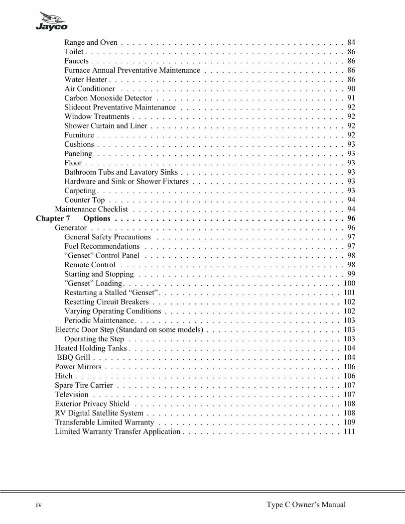
Range and Oven . . . . . . . . . . . . . . . . . . . . . . . . . . . . . . . . . . . . . . 84Toilet . . . . . . . . . . . . . . . . . . . . . . . . . . . . . . . . . . . . . . . . . . . . 86Faucets . . . . . . . . . . . . . . . . . . . . . . . . . . . . . . . . . . . . . . . . . . . 86Furnace Annual Preventative Maintenance . . . . . . . . . . . . . . . . . . . . . . . . 86Water Heater . . . . . . . . . . . . . . . . . . . . . . . . . . . . . . . . . . . . . . . . 86Air Conditioner . . . . . . . . . . . . . . . . . . . . . . . . . . . . . . . . . . . . . . 90Carbon Monoxide Detector . . . . . . . . . . . . . . . . . . . . . . . . . . . . . . . . 91Slideout Preventative Maintenance . . . . . . . . . . . . . . . . . . . . . . . . . . . . 92Window Treatments . . . . . . . . . . . . . . . . . . . . . . . . . . . . . . . . . . . . 92Shower Curtain and Liner . . . . . . . . . . . . . . . . . . . . . . . . . . . . . . . . . 92Furniture . . . . . . . . . . . . . . . . . . . . . . . . . . . . . . . . . . . . . . . . . . 92Cushions . . . . . . . . . . . . . . . . . . . . . . . . . . . . . . . . . . . . . . . . . . 93Paneling . . . . . . . . . . . . . . . . . . . . . . . . . . . . . . . . . . . . . . . . . . 93Floor . . . . . . . . . . . . . . . . . . . . . . . . . . . . . . . . . . . . . . . . . . . . 93Bathroom Tubs and Lavatory Sinks . . . . . . . . . . . . . . . . . . . . . . . . . . . . 93Hardware and Sink or Shower Fixtures . . . . . . . . . . . . . . . . . . . . . . . . . . 93Carpeting . . . . . . . . . . . . . . . . . . . . . . . . . . . . . . . . . . . . . . . . . . 93Counter Top . . . . . . . . . . . . . . . . . . . . . . . . . . . . . . . . . . . . . . . . 94
Maintenance Checklist . . . . . . . . . . . . . . . . . . . . . . . . . . . . . . . . . . . . 94Chapter 7 Options . . . . . . . . . . . . . . . . . . . . . . . . . . . . . . . . . . . . . . . 96
Generator . . . . . . . . . . . . . . . . . . . . . . . . . . . . . . . . . . . . . . . . . . . 96General Safety Precautions . . . . . . . . . . . . . . . . . . . . . . . . . . . . . . . . 97Fuel Recommendations . . . . . . . . . . . . . . . . . . . . . . . . . . . . . . . . . . 97“Genset” Control Panel . . . . . . . . . . . . . . . . . . . . . . . . . . . . . . . . . . 98Remote Control . . . . . . . . . . . . . . . . . . . . . . . . . . . . . . . . . . . . . . 98Starting and Stopping . . . . . . . . . . . . . . . . . . . . . . . . . . . . . . . . . . . 99”Genset” Loading. . . . . . . . . . . . . . . . . . . . . . . . . . . . . . . . . . . . . 100Restarting a Stalled “Genset” . . . . . . . . . . . . . . . . . . . . . . . . . . . . . . . 101Resetting Circuit Breakers . . . . . . . . . . . . . . . . . . . . . . . . . . . . . . . . 102Varying Operating Conditions . . . . . . . . . . . . . . . . . . . . . . . . . . . . . . 102Periodic Maintenance. . . . . . . . . . . . . . . . . . . . . . . . . . . . . . . . . . . 103
Electric Door Step (Standard on some models) . . . . . . . . . . . . . . . . . . . . . . . 103Operating the Step . . . . . . . . . . . . . . . . . . . . . . . . . . . . . . . . . . . . 103
Heated Holding Tanks . . . . . . . . . . . . . . . . . . . . . . . . . . . . . . . . . . . . 104BBQ Grill . . . . . . . . . . . . . . . . . . . . . . . . . . . . . . . . . . . . . . . . . . 104Power Mirrors . . . . . . . . . . . . . . . . . . . . . . . . . . . . . . . . . . . . . . . . 106Hitch . . . . . . . . . . . . . . . . . . . . . . . . . . . . . . . . . . . . . . . . . . . . . 106Spare Tire Carrier . . . . . . . . . . . . . . . . . . . . . . . . . . . . . . . . . . . . . . 107Television . . . . . . . . . . . . . . . . . . . . . . . . . . . . . . . . . . . . . . . . . . 107Exterior Privacy Shield . . . . . . . . . . . . . . . . . . . . . . . . . . . . . . . . . . . 108RV Digital Satellite System . . . . . . . . . . . . . . . . . . . . . . . . . . . . . . . . . 108Transferable Limited Warranty . . . . . . . . . . . . . . . . . . . . . . . . . . . . . . . 109Limited Warranty Transfer Application . . . . . . . . . . . . . . . . . . . . . . . . . . . 111
iv Type C Owner’s Manual

Chapter 1
INTRODUCTION TO RV OWNERSHIP
WELCOME
Thank you for purchasing your Jayco Recreation Vehicle and welcome to the world ofrecreation vehicle travel. Your purchase of a Jayco RV allows you to enter this unique world ofcamping and leisure in a grand style. Your Jayco RV has been designed and engineered to
offer you many comforts of home that will make your camping experience as enjoyable as
possible. Jayco recreation vehicles are designed, constructed and intended to be used as
temporary living quarters for recreational, camping and travel uses, all as defined in the
bylaws of the Recreation Vehicle Industry Association. Our recreation vehicles are not
intended for the hauling of cargo.
This owner’s manual was prepared to assist you in understanding the proper use and operationof various containment systems, servicing and maintenance of component parts, and explanationof your warranty protection. If you are a newcomer to RV travel, you will especially appreciatethe suggestions and “shop talk” information to be found throughout this manual to help youobtain the most pleasure from the use of your vehicle.
The information in this manual reflects the most current available to us at the time ofpublication. If you find the components in your recreation vehicle vary significantly from whatis described in this manual, please disregard that section and follow the instructions provided bythat particular component manufacturer. You should carefully read and understand this owner’smanual which is a supplement to various other instructions supplied by the manufacturers ofseparately warranted products.
Keep this owner’s manual in your recreation vehicle for handy reference. Get to know your newvehicle and how it operates. You should carefully read and understand these instructions andinformation supplied by manufacturers of separately warranted products, since they containimportant operating, safety, and maintenance instructions. If you have questions that are notadequately answered by this manual or other booklets, consult your dealer. If he cannotsatisfactorily answer your questions, he will call our staff or refer you to us for help.
Every effort has been made to provide you with a safe, dependable product. Your vehiclecomplies with applicable requirements of Federal Motor Vehicle Safety Standards, StateRegulations, Canadian Standards Associations (CSA) where applicable, and complies withrequirements of ANSI Standard A119.2, the nationally recognized “Standard For RecreationVehicles – Installation of Plumbing, Heating and Electrical Systems.” The Recreation VehicleIndustry Association (RVIA) and Canadian Standards Association (CSA) periodically inspectour production line and assist us in maintaining strict compliance with installation and safetystandards for those systems. Your follow-up with periodic safety inspections and a program
of preventive maintenance is important for the continuation of safe and trouble-free
operation.
Camping is a great way to relax and enjoy the outdoors with your friends and family. Pleaseremember to tread lightly on our beautiful land and leave only your footprints so that others mayenjoy nature as much as you did.
The Jayco FamilyJayco, Inc.
Introduction To RV Ownership 1
SAFETY CONSIDERATIONS
The terms NOTE, CAUTION and WARNING have specific meanings in this manual.
A NOTE provides additional information to make a step or procedure easier or clearer.Disregarding a NOTE could cause inconvenience, but would not be likely to cause damage orpersonal injury.
A CAUTION emphasizes areas where equipment damage could result. Disregarding aCAUTION could cause permanent mechanical damage. However, personal injury is unlikely.
A WARNING emphasizes areas where personal injury or even death could result from failureto follow instructions properly. Mechanical damage may also occur.
Reporting Safety Defects
If you believe that your vehicle has a defect which could cause a crash, injury or death, youshould immediately inform the National Highway Traffic Safety Administration (NHTSA) inaddition to notifying Jayco, Inc.
If NHTSA receives similar complaints, it may open an investigation, and if it finds that a safetydefect exists in a group of vehicles, it may order a recall and remedy campaign. However,NHTSA cannot become involved in individual problems between you, your dealer or Jayco, Inc.
NHTSA Customer Relations Dept.U.S. Department of Transportation Jayco IncorporatedWashington, D.C. 20590 P.O. Box 460, Middlebury, IN 46540Phone: 1-800-424-9393 Phone: 1-877-825-4782 or 1-219-825-0608Washington, D.C. Area: 368-0123 Business Hours: 8:00-5:00 Mon.–Fri. EST
You can also obtain other information about motor vehicle safety from the Hotline.
Safety in Using LP Gas
You should check for leaks at the connections on the LP gas system soon after purchase andinitial filling of LP tanks, and continued periodic checks of the system are recommended. Yourvehicle was manufactured to provide you with full access to all gas line connections. Leaks canbe found with a soapy water solution, which does not contain ammonia or chlorine, applied tothe outside of the gas piping connections: the soap will bubble at the leak. DO NOT USE
FLAME OR LIGHTED MATCHES TO TEST FOR LEAKS. Usually tightening ofconnections will close leaks. If not, ask an authorized dealer’s service department to make thenecessary tests and repairs.
ALTHOUGH THE MANUFACTURER AND DEALER HAVE PERFORMED TESTS FORLEAKAGE, THIS CHECK IS RECOMMENDED DUE TO THE VIBRATIONENCOUNTERED DURING TRAVEL.
As LP gas is heavier than air, leaking gas tends to flow to low places which will sometimespocket in low areas, such as the mini-motorhome floor. LP gas can usually be detected by anidentifiable odor similar to onions or garlic. Never light a match or allow any open flame in thepresence of leaking gas.
It is very important to have the LP gas turned off during refueling of tow vehicles. Some statesprohibit gas appliances to be operated during travel, especially in underground tunnels.
2 Type C Owner’s Manual
Never allow gas containers to be filled above the liquid capacity indicated on the container. If acontainer is overfilled, liquid gas may flow through the regulator causing it to freeze and/orintroduce a dangerous excessive gas pressure into the lines. In addition, an overfilled containerplaced in hot sunlight may expel excess gas through the relief valve and be susceptible toignition by any nearby open flame.
Electrical System Safety
Circuit breakers and fuses are installed to protect electrical circuits from overloading. Do notmake unauthorized changes to circuitry or add on fixed appliances yourself. If you wish to makechanges, consult your dealer and he will assist you in obtaining a safe installation.
An approved power supply cord has been supplied with the vehicle. Always use this cord forhook-up to the 120-volt source. Note that the cord has a three pin plug, which provides propergrounding through the third (round) pin. Grounding is your personal protection from electricalshock.
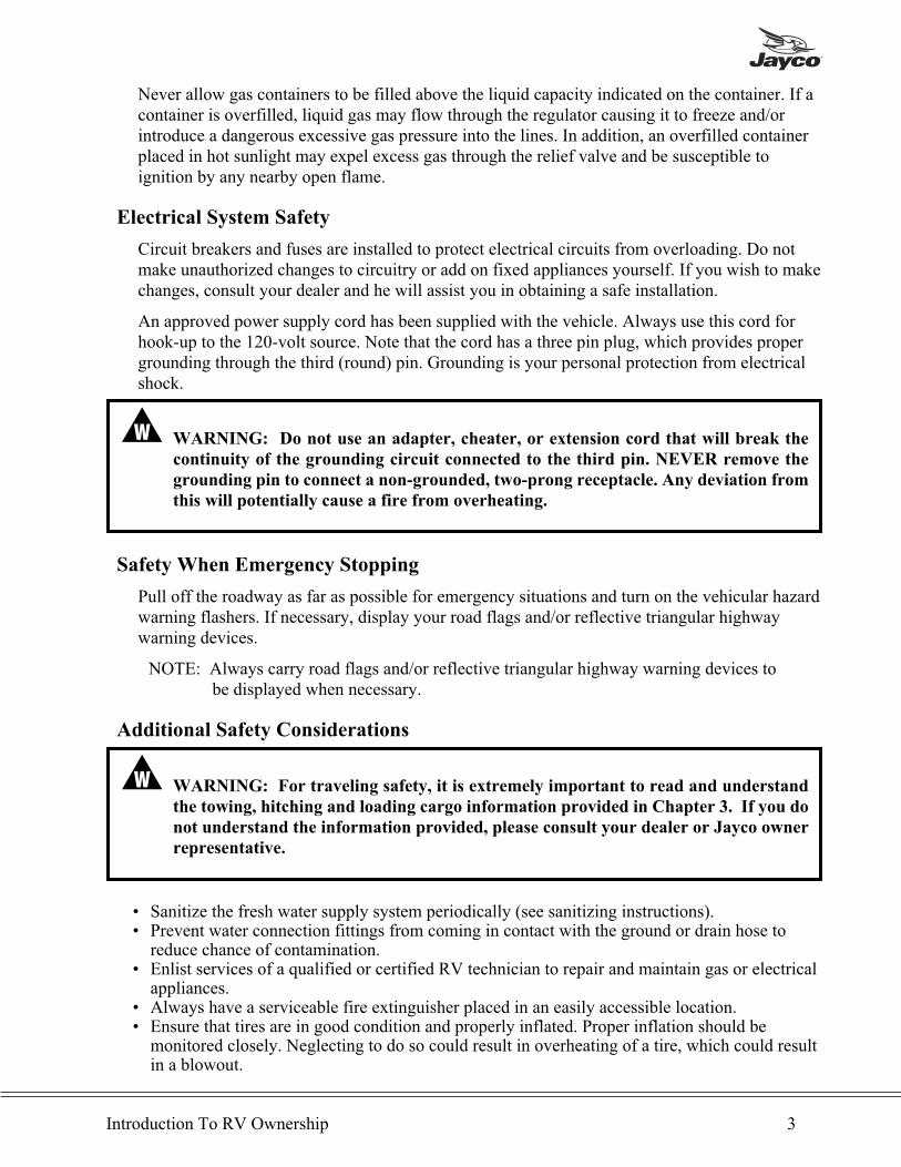
� WARNING: Do not use an adapter, cheater, or extension cord that will break the
continuity of the grounding circuit connected to the third pin. NEVER remove the
grounding pin to connect a non-grounded, two-prong receptacle. Any deviation from
this will potentially cause a fire from overheating.
Safety When Emergency Stopping
Pull off the roadway as far as possible for emergency situations and turn on the vehicular hazardwarning flashers. If necessary, display your road flags and/or reflective triangular highwaywarning devices.
NOTE: Always carry road flags and/or reflective triangular highway warning devices tobe displayed when necessary.
Additional Safety Considerations
� WARNING: For traveling safety, it is extremely important to read and understand
the towing, hitching and loading cargo information provided in Chapter 3. If you do
not understand the information provided, please consult your dealer or Jayco owner
representative.
• Sanitize the fresh water supply system periodically (see sanitizing instructions).• Prevent water connection fittings from coming in contact with the ground or drain hose toreduce chance of contamination.
• Enlist services of a qualified or certified RV technician to repair and maintain gas or electricalappliances.
• Always have a serviceable fire extinguisher placed in an easily accessible location.• Ensure that tires are in good condition and properly inflated. Proper inflation should bemonitored closely. Neglecting to do so could result in overheating of a tire, which could resultin a blowout.
Introduction To RV Ownership 3

• Check and tighten wheel lugs regularly, according to your chassis owner’s manualrecommendations.
• Check brakes in a safe area - not while traveling a busy highway.• Before leaving a camp area, ensure that the 120-volt electrical cord is properly stored.• Observe the warning labels attached to your vehicle concerning LP gas, water, electricity andloading.
• Observe the maintenance chart in Chapter 7 related to your respective vehicle.
INSURANCE
As with your automobile, it is important that you protect yourself and others with insurancecoverages for personal liability, theft, collision, property damage, etc. Your dealer will assistyou in obtaining appropriate insurance for your protection or you may check with the companywhich provides your automobile insurance.
EXTENDED USE
This mini-motorhome has been built for enjoyment in a recreational manner. It is not intendedto be used as full-time living quarters.
� CAUTION: Continuous living in your mini-motorhome could cause accelerated wear anddamage to components.
COLD WEATHER USE
• Proper care should be taken with the fresh water and draining systems to avoid freezingproblems. Consult your local dealer or RV supply house for additional material.
• Adequate gas and electrical supply is needed along with protection from possible freeze-upson the gas regulator.
• During cold weather usage, ventilation or the addition of a dehumidifier may be required toreduce condensation. Reference "Condensation."
CONDENSATION
Condensation is a natural phenomenon. The amount of condensation will vary with the climateconditions, particularly the relative humidity. Condensation occurs because there is water vaporpresent in the air, which each of us adds by breathing, bathing and cooking. The water vaporcollects where there is available air space, and when the temperature reaches the 'dew point' thewater vapor in the air condenses and changes to liquid form. Most people have experienced asimilar phenomenon when moisture forms on kitchen windows and bathroom mirrors duringcool weather.
Proper ventilation and, if needed, the use of a dehumidifier will assist in controlling thecondensation. Many RV and marine dealers carry small dehumidifiers especially sized forrecreation use. Condensation causes dampness, mildew, staining and if allowed to continue athigh levels, damage to the tent, paneling and wood structures.
4 Type C Owner’s Manual
Chapter 2
OBTAINING SERVICE
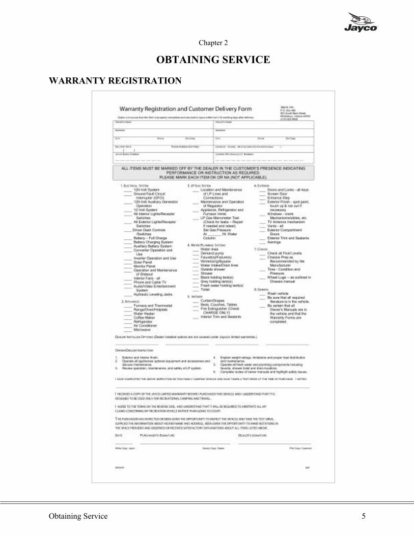
WARRANTY REGISTRATION
Obtaining Service 5
6 Type C Owner’s Manual

SERVICE PROCEDURES
Basic Service Procedures
We are interested in your satisfaction. Only by having your complete confidence andsatisfaction with our product and its service can we assure our continued success asmanufacturers of recreation vehicles. We have found that continuing a pleasant and effectiverelationship through our dealers is equally as important as maintaining the technical excellenceof our product. Your authorized dealer will cordially assist you in providing servicemaintenance, selection of options and instructions concerning the operation of your vehicle.
Should you have a problem with service, please follow these instructions in sequence.
1. Contact your selling dealer's service department for an appointment. Describe to the best ofyour knowledge the nature of the problem.
2. Contact the owner or General Manager of the dealership should the initial attempt fail withthe service department.
3. If further assistance is needed contact:
Customer Relations Dept.
Jayco IncorporatedP.O. Box 460Middlebury, IN 46540Phone: 1-877-825-4782 or 1-219-825-0608
Business Hours: Monday - Friday 8:00 - 5:00 EST
Give all the above information as requested along with the serial number of the vehicle inquestion and we will make every attempt to resolve your problem.
If you are traveling and are unable to locate an authorized Jayco dealer, or an authorized dealerfor the component needing service, please call our customer service office at 1-877-825-4782 or1-219-825-0608 or contact your selling dealer for assistance.
NOTE: Service at a non-authorized Jayco dealer should have prior authorization. Youwill be asked to return any mechanical parts replaced before reimbursementconsideration is made. Unauthorized or improper repairs may void the warrantyon that component.
Please keep your owner's manual, your copy of your warranty registration form and any
other related papers in your RV.
Please bear in mind that most problems arise from misunderstandings concerning warrantycoverage and service. In most instances, you will be referred to the dealer level and problemswill be resolved with the dealer's facilities and personnel.
CALIFORNIA LEMON LAW NOTICE: If you have determined that your vehicle has
non-conformities under the California Lemon Law, you must provide written notice of
the claimed defects directly to Jayco, Middlebury, Indiana at the address for warranty
service, and permit Jayco to perform a final repair attempt.
Obtaining Service 7

Dealer
Your authorized Jayco dealer has inspected and serviced your new Jayco RV He is authorized toservice and maintain your mini-motorhome as needed. All warranty repairs are to be performedby the selling dealer unless Jayco gives prior approval.
Some RV dealers may be authorized service centers for certain manufacturers of productswarranted separately. Check with your dealer before contacting others to reduce delays. If yourJayco dealer is not an authorized service center for the product in question, he can assist you inobtaining authorized service.
Factory
A factory service department is operated at our Middlebury, Indiana, manufacturing facility.Should your Jayco RV be in need of repairs and your dealer recommends that the factory makethe necessary repairs, it may be returned to our plant upon following these procedures:
1. You or your dealer must make an appointment prior to returning it to the factory servicedepartment.
2. All transportation costs are the responsibility of the owner. You may need to arrange foralternative accommodations for some types of repairs. Please be prepared accordingly.
Parts
Parts are available at most Jayco dealerships or your dealer can order parts for you as needed.Should you be unable to find a dealer in your local area, contact our Customer ServiceDepartment at 1-877-825-4782 or 1-219-825-0608 and we will assist you in providing partsthrough an authorized dealer or from Jay Parr Supply, our parts department located inMiddlebury, Indiana.
Owner's Responsibility
As a new owner of a Jayco recreation vehicle, you are responsible for regular and proper
maintenance. This will help you prevent conditions arising from neglect that are not
covered by your Jayco Limited Warranty.
Maintenance service should be performed in accordance with this owner's manual and any otherapplicable manuals.
As the owner, it is your responsibility and obligation to return the RV to an authorized dealer forrepairs and service. Reference your Limited Warranty for additional information. Because theauthorized dealer where you purchased your RV is responsible for its servicing before deliveryand has an interest in your continued satisfaction, we recommend that inspection, warranty andmaintenance services be performed by the dealership.
8 Type C Owner’s Manual
Chapter 3
OPERATING AND USING YOUR MINI-MOTORHOME
Your mini-motorhome has been designed and built to give you maximum comfort in a campingor recreational setting. Operating your mini-motorhome may be a new experience for you. Useextra caution in turning corners, climbing hills, stopping and other traffic conditions until youbecome familiar and comfortable with its operation and handling.
WEIGHTS AND CARGO CAPACITY
Under the present standards it is very important to provide an owner of a mini-motorhome withthe most accurate weight information available for safety reasons.
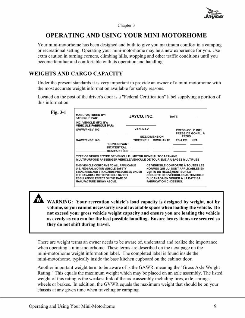
Located on the post of the driver's door is a "Federal Certification" label supplying a portion ofthis information.
� WARNING: Your recreation vehicle’s load capacity is designed by weight, not by
volume, so you cannot necessarily use all available space when loading the vehicle. Do
not exceed your gross vehicle weight capacity and ensure you are loading the vehicle
as evenly as you can for the best possible handling. Ensure heavy items are secured so
they do not shift during travel.
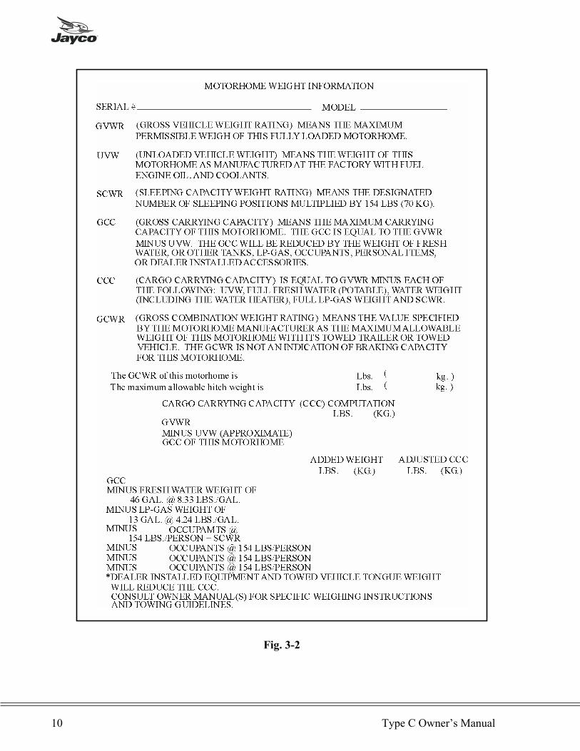
There are weight terms an owner needs to be aware of, understand and realize the importancewhen operating a mini-motorhome. These terms are described on the next page on themini-motorhome weight information label. The completed label is found inside themini-motorhome, typically inside the base kitchen cupboard on the cabinet door.
Another important weight term to be aware of is the GAWR, meaning the "Gross Axle WeightRating." This equals the maximum weight which may be placed on an axle assembly. The listedweight of this rating is the weakest link of the axle assembly including tires, axle, springs,wheels or brakes. In addition, the GVWR equals the maximum weight that should be on yourchassis at any given time when traveling or camping.
Operating and Using Your Mini-Motorhome 9
JAYCO, INC.MANUFACTURED BY:FABRIQUÉ PAR:
INC. VEHICLE MFG. BY:VÉHICULE FABRIQUÉ PAR:
GVWR/PNBV: KG V.I.N./N.I.V.
DATE
GAWR/PNBE: KGFRONT/DEVANTINT./CENTRALREAR/ARRIÉRE
SIZE/DIMENSIONTIRE/PNEU RIMS/JANTE
PRESS./COLD INFL.PRESS.DE GONFL. À
PSI/LPC KPA
TYPE OF VEHICLE/TYPE DE VÉHICULE: MOTOR HOME/AUTOCARAVANEMULTIPURPOSE PASSENGER VEHICLE/VÉHICULE DE TOURISME À USAGES MULTIPLES
THIS VEHICLE CONFORMS TO ALL APPLICABLEU.S. FEDERAL MOTOR VEHICLE SAFETYSTANDARDS AND STANDARDS PRESCRIBED UNDERTHE CANADIAN MOTOR VEHICLE SAFETYREGULATIONS EFFECT ON THE DATE OFMANUFACTURE SHOWN ABOVE.
CE VÉHICULE CONFORME À TOUTES LESNORMES QUI LUI SONT APPLICABLES ENVERTU DU REGLÈMENT SUR LASÉCURITÉ DES VÉHICULES AUTOMOBILEDU CANADA EN VIGUER À LA DATE SAFABRICATION CI-DESSUS.
FROID
Fig. 3-1
10 Type C Owner’s Manual
Fig. 3-2
� CAUTION: We recommend weighing your mini-motorhome when it's completely loaded.Follow the GVWR guidelines. DO NOT exceed the GVWR. Refer to the weighinginstructions on the following pages
� WARNING: The actual weight of the vehicle, passengers, all options, liquids, the hitch
weight of your towed vehicle and your personal cargo is important for you to know so
you do not exceed the gross vehicle weight rating of the . The volume of space available
for storage may exceed the amount of available cargo capacity. Large storage
compartments have been designed to accommodate normal camping items, such as
lawn chairs, portable grill, sporting goods (fishing poles, golf clubs), which are bulky,
but not necessarily heavy. DO NOT EXCEED YOUR GVWR - This means you should
weigh your vehicle as loaded for your normal travel to determine the actual weight. If
you exceed the GVWR, you MUST remove items from the mini-motorhome, or drain
liquids, then re-weigh the vehicle to ensure you have achieved a safe weight. Never
travel with full holding tanks. This not only wastes gas, but depending upon the
location of the tank, can affect handling characteristics. Weight labels are posted
inside a cabinet door inside all Jayco RV's so you can make a decision before you buy
about how much cargo capacity is important for you personally.
� WARNING: DO NOT overload your mini-motorhome. Overloading either the front
axle, rear axle or behind the rear axle may result in adverse handling characteristics
and damage to the chassis. Follow the GVWR when loading your vehicle for safety.
Operating and Using Your Mini-Motorhome 11

HITCH - SEE CHAPTER 7 "OPTIONS"
Your mini-motorhome is designed to be a recreation vehicle, however it does have towingcapabilities as well as limitations. A class 3 hitch receiver is available with a 3,500# (1588kilograms) gross weight capacity. A variety of extender bars of different ratings are available.Remember the limit of weight on the hitch and chassis.
The above warning label (Fig. 3-3) is attached to the exterior of your mini-motorhome near thehitch receiver bar and in the interior adjacent to or immediately below the RVIA WeightInformation Label. This is typically on the back of an interior cabinet door in the kitchen. Foryour safety, please review and understand all towing and braking capacities of your vehicle. Foradded information, consult with your chassis dealer or manufacturer.
LOADING CARGO
� WARNING: For traveling safety, it is important to make sure the tie down straps are
secured on all appliances such as the television, coffee maker, etc. Vibration caused
during travel will move the appliances creating the potential for them to fall out of
their cabinets possibly causing injury.
The loading of travel and camping equipment along with food and liquids requires carefulconsideration. Lightweight and bulky items such as paper products, bedding, and clothes shouldbe stored in overhead cabinets. Heavy items such as cooking equipment should be placed inlower cabinets. Canned food should be in a pantry, if so equipped, or in lower cabinets. Heavyitems should be secured to avoid shifting during travel. Keep heavy items in front of the rearaxle as too much weight behind the axle can affect steering conditions.
Distributing weight throughout the mini-motorhome will enable the unit to handle and performwell during travel.
When you are finished loading the mini-motorhome, weigh the vehicle. See the next section forweighing instructions.
12 Type C Owner’s Manual
WARNING!YOUR MOTORHOME CHASSIS IS RATED FOR TOWING OPERATION AT GVWR NOT GCWR. CONSULT YOURCHASSIS OWNER’S MANUAL(S) FOR SPECIFIC WEIGHING INSTRUCTIONS AND TOWING GUIDELINES. THEBRAKING CAPACITY OF YOUR MOTORHOME IS NOT NECESSARILY AS GREAT AS THE TOWING CAPACITY.SEPARATE BRAKING SYSTEMS SHOULD BE USED FOR CONTROL OF A TOWED VEHICLE, (AUTO, TRAILER,BOAT, ETC.), BEHIND THE MOTORHOME. IF THE TOWED BEHICLE MEETS OR EXCEEDS THE MINIMUM WEIGHTAS DETERMINED BY THE CHASSIS MANUFACTURER, (THIS MINIMUM WEIGHT RATING WILL VARY BY CHASSISAND CHASSIS MANUFACTURER), CONTACT YOUR CHASSIS DEALER OR MANUFACTURER FOR ASSISTANCE INDETERMINING WHETHER A SEPARATE BRAKING SYSTEM IS RECOMMENDED AND WHAT LIMITS THERE AREFOR YOUR TOWING COMBINATION AND TRAVELING SAFETY.
Fig. 3-3
� WARNING: Rear bumper on the frame of the mini-motorhome is NOT designed to
carry over 100 lb. of weight. Installation of items exceeding 100 lb. may cause metal
fatigue and weld stress. Should such failures occur, it could damage your property
and endanger vehicles following your mini-motorhome during travel, possibly
causing an accident.
� WARNING: We recommend that you DO NOT travel with full holding tanks. Full
holding tanks are not calculated into the cargo capacity of your mini-motorhome. The
weight from full holding tanks will greatly diminish the cargo capacity and possibly
cause you to exceed the gross vehicle weight rating. This can affect suspension
components, reduce fuel economy, and create adverse handling characteristics. If you
are dry camping and cannot immediately empty your tanks, reduce your speed until
you reach a dumping station.
WEIGHING INSTRUCTIONS
Your recreation vehicle must be weighed fully loaded, that is, with passengers, food, clothing,fuel, water, propane, supplies, etc. Any towed vehicle (car/pickup, boat or trailer) or item loadedon brackets on the back of the recreation vehicle, such as bikes or motorcycles, should also beincluded in the weighing.
There are three types of scales:
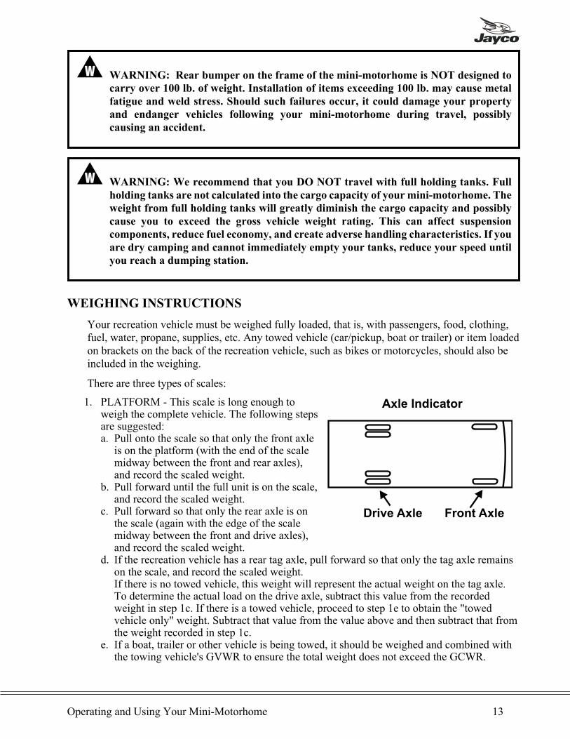
1. PLATFORM - This scale is long enough toweigh the complete vehicle. The following stepsare suggested:a. Pull onto the scale so that only the front axle
is on the platform (with the end of the scalemidway between the front and rear axles),and record the scaled weight.
b. Pull forward until the full unit is on the scale,and record the scaled weight.
c. Pull forward so that only the rear axle is onthe scale (again with the edge of the scalemidway between the front and drive axles),and record the scaled weight.
d. If the recreation vehicle has a rear tag axle, pull forward so that only the tag axle remainson the scale, and record the scaled weight.If there is no towed vehicle, this weight will represent the actual weight on the tag axle.To determine the actual load on the drive axle, subtract this value from the recordedweight in step 1c. If there is a towed vehicle, proceed to step 1e to obtain the "towedvehicle only" weight. Subtract that value from the value above and then subtract that fromthe weight recorded in step 1c.
e. If a boat, trailer or other vehicle is being towed, it should be weighed and combined withthe towing vehicle's GVWR to ensure the total weight does not exceed the GCWR.
Operating and Using Your Mini-Motorhome 13
Axle Indicator
Drive Axle Front Axle
2. SEGMENTED PLATFORM - Platform scales with segmented sections can provideindividual axle weights and total vehicle weights simultaneously, when the vehicle ispositioned properly.Position the vehicle on the scales so that each axle is centered as much as possible onseparate segments, and record the weight. Reposition the vehicle so that only one side is onthe scale, again centered on the segment as much as possible. Subtract the weighed wheelpositions from the total axle weights to determine the unweighed wheel positions' weights.
3. SINGLE AXLE - This scale weighs one axle at a time. Drive your front axle onto the scaleand stop long enough for the weight to be recorded. Pull vehicle forward until the rear axle ison the scale. To obtain the gross vehicle weight, add the two axle loads together. To obtainthe individual wheel position weights, repeat this process with only one side of the recreationvehicle on the scale.
NOTE: Even though the weight of the total axle may be within the axle's rating, it may beoverloaded on one side. This causes one wheel position to be overloaded. Therefore,side-to-side weighing should also be done.
a. To determine individual wheel position weights, it is necessary to repeat the previousthree steps (1a, 1b, and 1c), but this time, use only one side of the scale.
b. To calculate the opposite side of the vehicle wheel position weight, subtract this side'sweights from the weights recorded in steps 1a, 1b, and 1c.
Your recreation vehicle must remain as level as possible on the scale (even though an axle orside is not physically on the scale). Obviously, to obtain the side-to-side weights, there must beenough space on either side of the scale to accommodate the recreation vehicle being partiallyoff the scale.
If there is a difference in the weights on one side of the vehicle as compared to weights on theother side, components (tires, wheels, brakes, springs, etc.) on the heavier side could beoverloaded, even though the total axle load is within the GAWR. It is important to redistributethe load to avoid component failure, as well as to improve the handling characteristics of thevehicle.
With these actual weights, it is now possible to compare them against the GAWR, GVWR andtire capacities. These weights are also what should be used to help determine the proper airpressure for the tires.
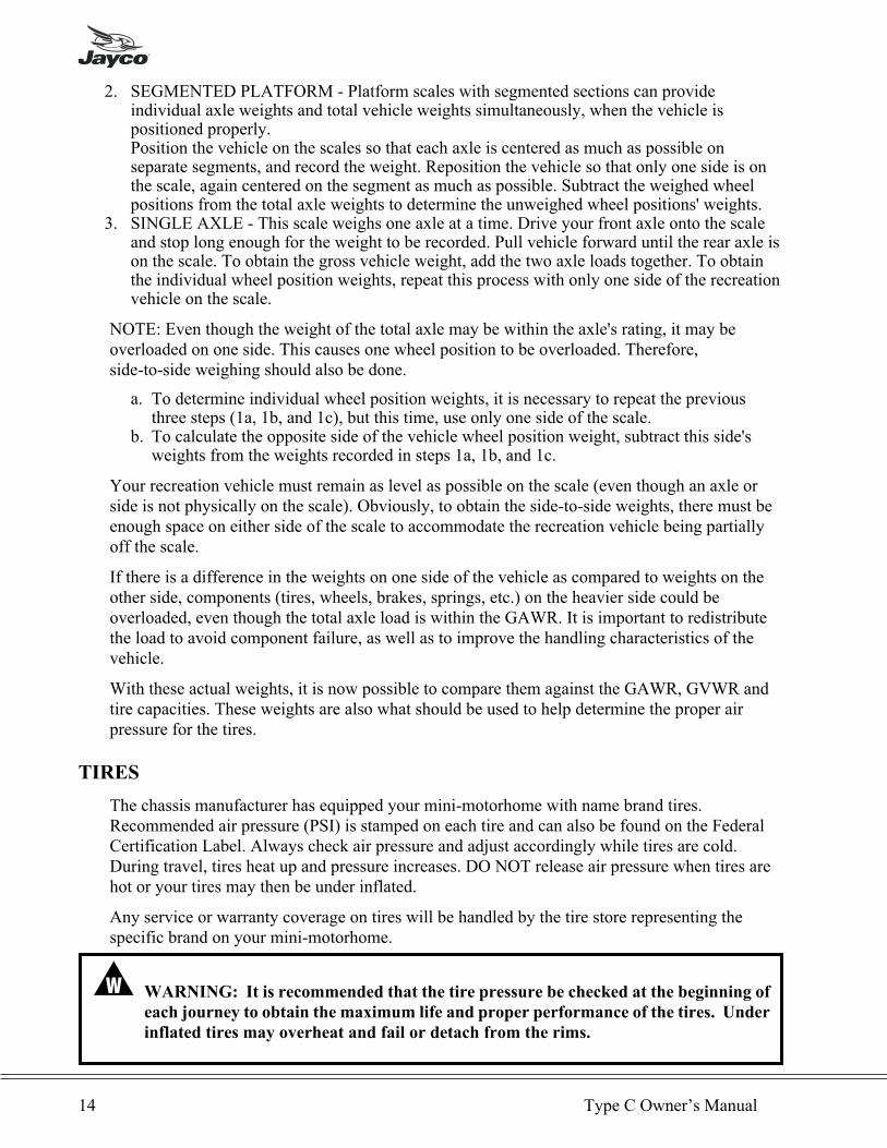
TIRES
The chassis manufacturer has equipped your mini-motorhome with name brand tires.Recommended air pressure (PSI) is stamped on each tire and can also be found on the FederalCertification Label. Always check air pressure and adjust accordingly while tires are cold.During travel, tires heat up and pressure increases. DO NOT release air pressure when tires arehot or your tires may then be under inflated.
Any service or warranty coverage on tires will be handled by the tire store representing thespecific brand on your mini-motorhome.
� WARNING: It is recommended that the tire pressure be checked at the beginning of
each journey to obtain the maximum life and proper performance of the tires. Under
inflated tires may overheat and fail or detach from the rims.
14 Type C Owner’s Manual
WHEEL LUGS
Ensure that wheel lugs are tight as specified in the chassis manual. When your vehicle is new ora tire has been removed for any reason, re-torque the lug nuts at 10, 25 and 50 miles (15, 40 and100 kilometers) and every 3,000 miles (5000 kilometers) thereafter.
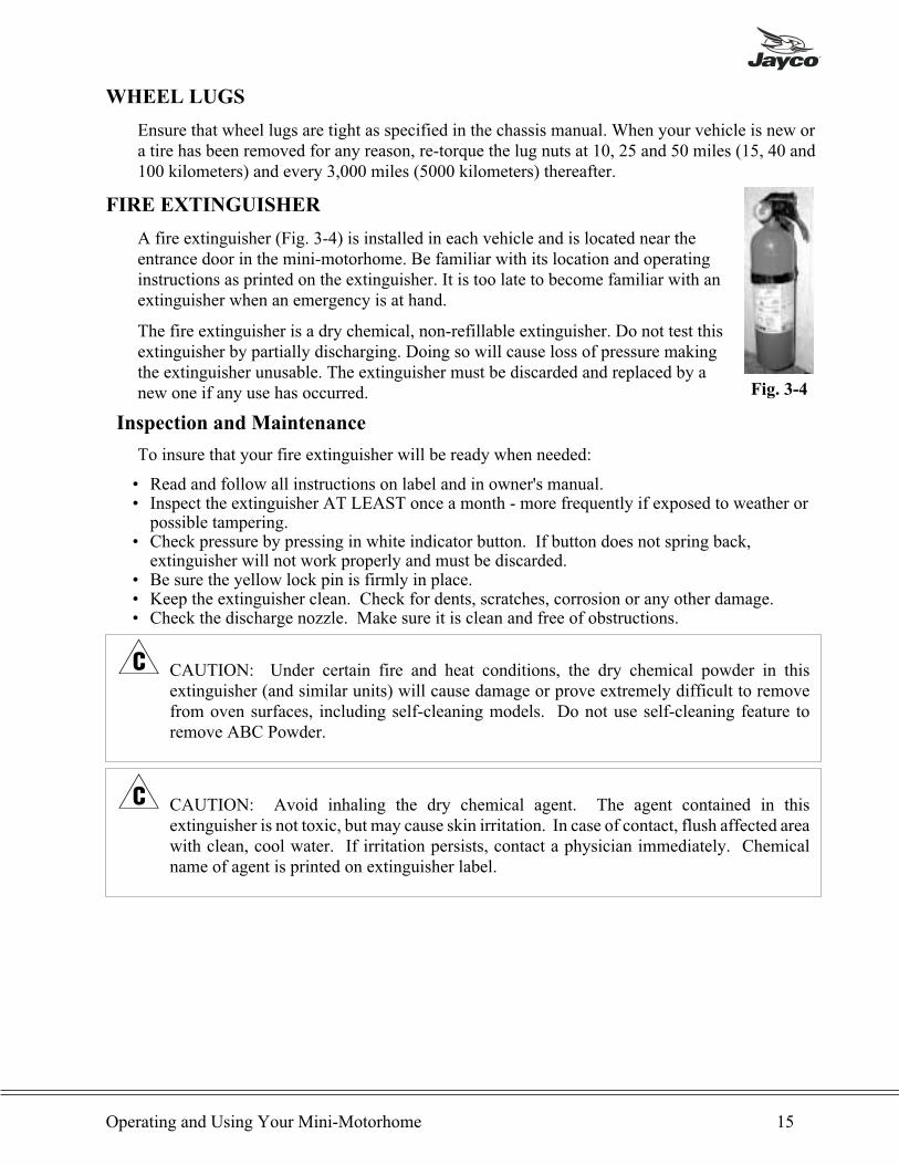
FIRE EXTINGUISHER
A fire extinguisher (Fig. 3-4) is installed in each vehicle and is located near theentrance door in the mini-motorhome. Be familiar with its location and operatinginstructions as printed on the extinguisher. It is too late to become familiar with anextinguisher when an emergency is at hand.
The fire extinguisher is a dry chemical, non-refillable extinguisher. Do not test thisextinguisher by partially discharging. Doing so will cause loss of pressure makingthe extinguisher unusable. The extinguisher must be discarded and replaced by anew one if any use has occurred.
Inspection and Maintenance
To insure that your fire extinguisher will be ready when needed:
• Read and follow all instructions on label and in owner's manual.• Inspect the extinguisher AT LEAST once a month - more frequently if exposed to weather orpossible tampering.
• Check pressure by pressing in white indicator button. If button does not spring back,extinguisher will not work properly and must be discarded.
• Be sure the yellow lock pin is firmly in place.• Keep the extinguisher clean. Check for dents, scratches, corrosion or any other damage.• Check the discharge nozzle. Make sure it is clean and free of obstructions.
� CAUTION: Under certain fire and heat conditions, the dry chemical powder in thisextinguisher (and similar units) will cause damage or prove extremely difficult to removefrom oven surfaces, including self-cleaning models. Do not use self-cleaning feature toremove ABC Powder.
� CAUTION: Avoid inhaling the dry chemical agent. The agent contained in thisextinguisher is not toxic, but may cause skin irritation. In case of contact, flush affected areawith clean, cool water. If irritation persists, contact a physician immediately. Chemicalname of agent is printed on extinguisher label.
Operating and Using Your Mini-Motorhome 15
Fig. 3-4

TV ANTENNA
Raising Antenna to Operating Position
Turn the elevating crank clockwise in the UP direction about thirteen turns or until someresistance to turning is noted. (Fig. 3-5)
On Amplified models, 12-Volt DC power is required. Turn the power supply ON to use eitherthe front or rear TV outlet. (Fig. 3-6) Neither outlet will work unless the power supply switch ison. Turning the power supply on sends 12-volt DC through the cable to the antenna. The voltageenergizes the transistors on the amplifier in the antenna head. The TV signal comes back downthe cable to the outlets.
After the antenna is in the full UP position, pull down on the round knob with both hands until itdisengages from the ceiling plate. Rotate the knob for best picture. (Fig. 3-7)
To Test System
1. Make sure the TV set is working properly.2. Switch the power supply ON and OFF to see if there is a difference
in the picture quality while watching TV. If there is NO difference, refer to manufacturer'smanual for further testing procedures.
� CAUTION: The power supply should be turned OFF when connecting/disconnecting thecables to the power supply and antenna, but should be turnedONwhen testing for voltage.
Lowering Antenna to Travel Position
Rotate the antenna until the pointer on the directional handle aligns with the pointer on theceiling plate. (Fig. 3-7) Turn the elevating crank counterclockwise in the DOWN direction aboutthirteen turns or until resistance is noted. (Fig. 3-5) The antenna is now locked in the travelposition.
� CAUTION: When lowering the antenna, never lower it into any position except the travelposition. Failure to lower antenna into the travel position before traveling may damage theantenna and is not covered by warranty.
Maintenance
See "TV Antenna Maintenance" in Chapter 7.
16 Type C Owner’s Manual
� WARNING: DO NOT
connect high current
devices such as hair
dryers to this receptacle.
Maximum current rating
of this receptacle is 8
amps at +12-volt DC.Fig. 3-5
Fig. 3-7
WINEGARD
12VDC 8 AM P MAX
Fig. 3-6

SEAT BELTS
Three-point shoulder harnesses and lap belts are provided at the front driver and passenger seatsby the chassis manufacturer. See the chassis manual for operating instructions.
For the recreation vehicle section, the dinette, sofa, and barrel chairs have a two-point lap seatbelts installed. To operate, slide the loose end of the seat belt into the buckle until it "clicks" inplace. Adjust by pulling the loose strap end until it fits snugly on your upper lap. To release theseat belt, push the button on the buckle and pull apart.
� WARNING: Your mini-motorhome is equipped with seatbelts at all seat locations.
Having seatbelts at all seat locations does not necessarily mean that all seats can be
occupied at one time, because you cannot exceed the GVWR of your vehicle. When
calculating the loaded weight of the vehicle, make sure to include all people who will be
riding in the unit. The GVWR of your unit is located on the Motorhome Weight
Information label.
NOTE: Pregnant women should consult a physician for seat belt use.
DRIVING
Driving a mini-motorhome is similar to an automobile. Become familiar with all controls andhandling ability. Remember, a mini-motorhome sits higher on a larger chassis and the wheelbase and RV house is longer which will require more space to turn and change lanes duringtravel. In addition, the mini-motorhome is heavier than a passenger car, thus a longer distance isrequired to pass another vehicle. Always use turn signals when changing lanes. More distancemay be required to stop your mini-motorhome.
CARBON MONOXIDE DETECTOR
Carbon monoxide (CO) is an odorless, colorless, tasteless gas that is extremely dangerous tohumans and animals. The following symptoms are indicative of individuals exposed to carbonmonoxide:
• Mild Exposure: Slight headache, nausea, vomiting, fatigue• Medium Exposure: Severe headache, drowsiness, confusion, fast heart rate• Extreme Exposure: Unconsciousness, convulsions, cardiorespiratory failure, death
A UL listed carbon monoxide detector has been installed in your mini-motorhome. It isdesigned to detect toxic CO fumes. It is not a substitute for other combustible gas, fire or smokealarms.
Operating and Using Your Mini-Motorhome 17
Procedures to Take During an Alarm
� WARNING: The activation of the CO detector is a warning that indicates the
presence of carbon monoxide!
� WARNING: Do not disconnect the CO detector to silence the alarm. The detector is
designed to sense when the level of CO in the air falls below the danger level. All
individuals should remain outside the unit until the alarm is silent.
If someone is suffering from an upset stomach, headache or other symptom, immediately moveto a location that has fresh air. Ensure that everyone is accounted for, including pets. Call theFire Department. Do not reenter the unit until the source of carbon monoxide has been locatedand repaired by a qualified technician.
� WARNING: Low levels of CO have been linked to brain and vital organ damage to
unborn infants with no effect on the mother. Pregnant women should leave the unit
immediately if an alarm is sounded and not return until the unit has been repaired and
aired out thoroughly.
If no one exhibits the symptoms associated with carbon monoxide:
1. Push the reset button.2. Turn off all sources of combustion including the water heater, furnace, stove, oven,
motorhome engine.3. Open the windows and doors and move to a location that has fresh air.4. Call a qualified technician and have the problem corrected before restarting the appliances
and/or vehicles.
EMERGENCY EXIT WINDOW
An emergency exit window is installed in your mini-motorhome, typically on the rear wall orsidewall opposite the entry door. The window is identified by red snap latches and a white labelwith red letters indicating "EXIT."
This window will allow a quick exit from the vehicle during an emergency if access to the maindoor is not available. An emergency exit may also be available through the driver's side cabdoor. Practice opening the window BEFORE an emergency occurs, and make sure all occupantsknow how to operate it.
18 Type C Owner’s Manual
SLIDEOUT ROOM OPTION
The slideout is designed for additional floor space and comfort. Mechanical components aregear driven and produced by Power Gear Company. Read ALL instructions in the next fewpages before operation to become familiar with the system.
� CAUTION: Do not place excessive weight in the slideout room.
Components
The slideout system has numerous major components and are as follows:
• One inner rail drive assembly to support room weight.• A 12-volt DC motor and drive shaft that will operate the room using energy from an onboardrecreation vehicle battery.
• A manual override system that allows you to move the room in or out in the event of a powerloss.
� WARNING:
• Ensure that the mini-motorhome is level before operating the slideout room.
• Ensure there are no obstructions blocking the path of the room when it is
moving.
• Make sure that the room path and the room itself are clear of people and
objects before operating.
• Keep away from the slide rails when the room is in motion.
• The gear assembly may pinch or catch on loose clothing causing personal
injury.
• Always install transit bar for storage and transportation.
• The slideout room should be clear of people during operation.
Failure to follow these instructions could result in serious injury or death.
Operations
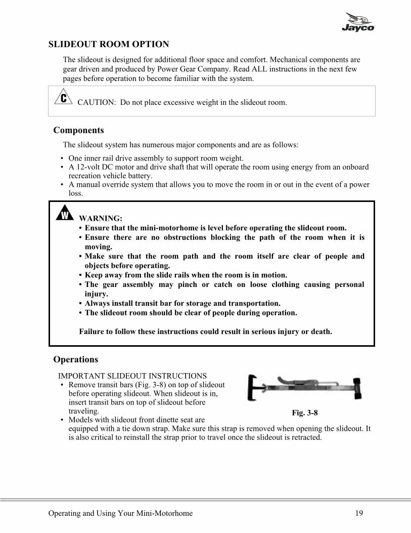
IMPORTANT SLIDEOUT INSTRUCTIONS• Remove transit bars (Fig. 3-8) on top of slideoutbefore operating slideout. When slideout is in,insert transit bars on top of slideout beforetraveling.
• Models with slideout front dinette seat areequipped with a tie down strap. Make sure this strap is removed when opening the slideout. Itis also critical to reinstall the strap prior to travel once the slideout is retracted.
Operating and Using Your Mini-Motorhome 19
Fig. 3-8
EXTENDING ROOM1. Battery(ies) must be fully charged and connected. Mini-motorhome should be hooked up to
120-volt AC power if possible.2. Turn mini-motorhome master battery switch on.3. The mini-motorhome must be level and if the unit has stabilizer jacks they must be in the
down position.
� CAUTION: Additional support jacks are not needed under the slideout. Damage can occurto your slideout room from improper use of support jacks.
4. Remove "transit bars" from behind the top fascia board located above slideout room.5. For models with slideout front facing dinette seat, remove the tie down strap on the aft end of
the rear dinette seat.6. Ensure that there are no items left between slideout and cabinetry.7. Locate slideout master control switch.8. To move room out, press the "out" button on switch and hold until motor stops.9. Release button as switch is spring loaded. Travel time - approximately twenty seconds.
RETRACTING ROOM1. Remove all objects in front of the room.2. Press the "In" button to bring room in and hold until motor stops.3. Release switch button.4. Install "transit bars" in proper location as indicated on the wall.5. Install the rear dinette seat tie down strap.
� WARNING: For models with a slideout front facing dinette seat, confirm that the tie
down strap is installed correctly prior to travel.
� CAUTION: IMPORTANT! Never store slideout without the transit bars installed. Thishelps seal the slideout in the closed position.
20 Type C Owner’s Manual

Overriding The Mini-Motorhome Slideout System
The Power Gear slideout system is equipped with a manual crank override that allows you toextend or retract the slideout if there is a loss of power.
If the system will not move when the switch is pressed, check the following:
• Is the battery connected?• Does the battery have a full charge?• Is the mini-motorhome master battery switch turned "ON"?• Are the transit bars and tie down strap (if applicable) removed?
After checking the above, follow these steps to move the slideout manually:
1. Rotate the lever on the back side of the motor counter-clockwise about 1/8 turn (Fig. 3-10).This will release the brake that locks the slideout in place.
2. Access the manual over ride. For some models it is located in front of the slideout railassembly and for other models, it will be found behind the drivers seat.• For models with the override in front of the slideout rail assembly, using a 3/4" or 1/2"drive rachet with a 3/4" socket, crank the slideout until it is fully retracted (or extended).
• For models with the override behind the drivers seat, using a 3/4” drive rachet with a1-1/8” socket, crank the slideout until it is fully retracted (or extended).
3. When the slideout is fully retracted (or extended), apply pressure to the ratchet handle andreturn the brake release lever to its normal downward position (Fig. 3-10). This will ensurethat the slideout is locked in a sealed position.
4. Install the transit bars and tie down strap (if applicable) and take the unit to a Jayco dealer forservice.
Operating and Using Your Mini-Motorhome 21
MAIN ROOM MOTOR
ROTATE TORELEASE BRAKE
ROTATE TORELEASE BRAKEBEDROOM MOTOR WITHOUT BRAKE LEVER
BEDROOM / MOTORHOME MOTORWITH BRAKE LEVER
Fig. 3-10
OUTER RAIL ASSEMBLY MOUNTING BRACKETS
MANUALOVERRIDE
MOTOR
ROOMMOUNTING
KIT
MAIN ROOM SLIDEOUT
INNER RAIL ASSEMBLY
DRIVER’SSEAT
Fig. 3-9
� WARNING: When the slideout motor brake is released the slideout will not lock into
place, and therefore it will not be sealed from the outdoors! When the slideout has
been retracted, be sure to install the transit bars and the tie down strap (if applicable)
and return the break release lever to its downward position in order to seal and lock
the slideout.
� WARNING: For models with a slideout front facing dinette seat, confirm that the tie
down strap is installed correctly prior to travel.
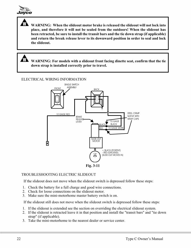
ELECTRICAL WIRING INFORMATION
TROUBLESHOOTING ELECTRIC SLIDEOUT
If the slideout does not move when the slideout switch is depressed follow these steps:
1. Check the battery for a full charge and good wire connections.2. Check for loose connections on the slideout motor.3. Make sure the mini-motorhome master battery switch is on.
If the slideout still does not move when the slideout switch is depressed follow these steps:
1. If the slideout is extended see the section on overriding the electrical slideout system.2. If the slideout is retracted leave it in that position and install the "transit bars" and "tie down
strap" (if applicable).3. Take the mini-motorhome to the nearest dealer or service center.
22 Type C Owner’s Manual
BRAKERELEASELEVER
STEEL CRIMP
SLEEVE WITH
WRAP CAPS
SINGLE SWITCH
ASSEMBLY
SLIDE-OUTMOTOR
BACK
BLACK
RED 10 GAGE WHITE
10 GAGE
BLACK
CW
+ BLACK (POSITIVE)- RED (GROUND)(SLIDE-OUT MOVES IN)
10 GAGE RED
OUT
IN
FRONT
Fig. 3-11
If the slideout extends crooked or only one side moves follow these steps:
1. Follow steps 1-4 of the section on overriding the slideout system to disconnect the motor.2. Retract slideout using the hand crank. You may need to push on the side that is not sliding to
get it to retract all the way.3. Once the slideout is fully retracted, install the "transit bars" and "tie down strap" (if
applicable).4. Take your mini-motorhome to the nearest dealer or service center.
SETUP FOR CAMPING
Leveling your RV is important for several reasons:
1. The refrigerator is designed to operate when level for best performance due to the absorptionsystem.
2. The water drainage systems are designed with proper slope and must be level for properoperation.
3. A level motorhome is more comfortable for sleeping and walking.4. The oven performs best when level.
For leveling the mini-motorhome, carry a quantity of 2"x6"x12" blocks to place under the tireswhen parking on an uneven campsite. "Chock" the tires to prevent the vehicle from rolling offthe blocks. If the vehicle is equipped with stabilizer jacks, use them for support as needed. DONOT use these jacks for raising the vehicle.
After correctly leveling and supporting your mini-motorhome, connect items such as the freshwater supply and holding tank drain hose.
� CAUTION: To prevent 120-volt AC electrical power surges from damaging connectedloads, it is recommended to follow this procedure:
1. Enter mini-motorhome and turn off ALL 120-volt circuit breakers2. Exit mini-motorhome and plug in power cord, 120-volt AC3. Return to mini-motorhome and turn on MAIN circuit breaker first.4. Now turn on the remainder of circuit breakers, A, B, etc.
You may also possess a volt meter to read voltage coming from power source. Campgroundsoccasionally have low or high voltage. Any prolonged overload will shorten the life of 120-voltsystem and appliances.
Open the valve at the LP propane tank SLOWLY. Light pilot lights as needed. There may be airin the LP lines and five to thirty seconds of time is needed to bleed air before lines are filledwith LP vapor. Instructions for lighting and shutting down your LP gas powered appliances arein each appliance information manual provided with each appliance, as well as in Chapter 4.
Operating and Using Your Mini-Motorhome 23
STORING YOUR MINI-MOTORHOME
To maintain your mini-motorhome, follow these suggestions when the vehicle is being stored:
1. Drive the mini-motorhome once every thirty days for thirty minutes to one hour.2. Store the vehicle with full engine fluid levels.3. Keep the fuel tank full to prevent condensation. In addition, adding fuel stabilizer will also
aid in preventing condensation.4. Keep the battery charge levels in top condition. (Reference Chapter 4 for additional
information.)5. Turn off the mini-motorhome master battery switch.
Depending upon your area and where your recreation vehicle is stored, your mini-motorhomemay be a target for damage from rodents and insects. To protect your mini-motorhome, neverleave food inside the vehicle and make sure all surfaces are clean. You may want to place rodentcontrol products in the vehicle during periods of storage. Mice especially can do a tremendousamount of damage to the drapes, cushions, etc. particularly in the winter months. Storingrecreation vehicles in fields make them particularly inviting to rodents. Periodically inspect yourvehicle during storage and seal off any areas which can offer an entry point to rodents or insects.Please remember to remove any screens or tape you have used to seal openings before you usethe mini-motorhome again. Special interest publications, such as articles and books offeredthrough TL Enterprises (Trailer Life, Motorhome, etc.) can offer you additional, practical adviceon the proper storage of your vehicle. Damage from rodents or insects are NOT covered underyour Jayco Limited Warranty.
24 Type C Owner’s Manual
Chapter 4
THE SYSTEMS
PLUMBING SYSTEM
Included in your Jayco recreation vehicle is a complete fresh water system. Each component isexplained along with its operation.`
Tanks
A water tank is permanently installed in your recreation vehicle. On some models it is locatedinside of the mini-motorhome under a bed, dinette or sofa. Other models may have an externaltank under the floor between frame members.
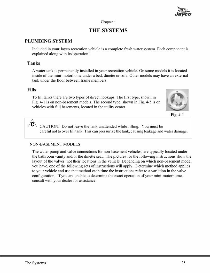
Fills
To fill tanks there are two types of direct hookups. The first type, shown inFig. 4-1 is on non-basement models. The second type, shown in Fig. 4-5 is onvehicles with full basements, located in the utility center.
� CAUTION: Do not leave the tank unattended while filling. You must becareful not to over fill tank. This can pressurize the tank, causing leakage andwater damage.
NON-BASEMENT MODELS
The water pump and valve connections for non-basement vehicles, are typically located underthe bathroom vanity and/or the dinette seat. The pictures for the following instructions show thelayout of the valves, not their locations in the vehicle. Depending on which non-basement modelyou have, one of the following sets of instructions will apply. Determine which method appliesto your vehicle and use that method each time the instructions refer to a variation in the valveconfiguration. If you are unable to determine the exact operation of your mini-motorhome,consult with your dealer for assistance.
The Systems 25
Fig. 4-1

Method 1:• Connect a garden hose from the watersupply line to the “city waterconnection”. (Fig. 4-1)
• Make sure that valves 1, 2, 3, 5, and 6are closed and valve 4 is open. (Fig.4-2 & 4-3)
• Open the valve on the water supplyline.
• Enter the unit and open the faucets tobleed air from the lines. The waterheater will fill first, followed by thesupply lines and faucets. When thelines are near full, you may experiencecome air pockets. Allow them toescape before closing the faucets.
• Close valve 4. (Fig. 4-2)
Method 2:
• Connect a garden hose from the watersupply line to the “city waterconnection”. (Fig. 4-1)
• Make sure that valves 1, 2, 5, and 6 areclosed and valves 3 and 4 are open.(Fig. 4-2 & 4-4)
• Open the valve on the water supplyline.
• Enter the unit and open the faucets tobleed air from the lines. The waterheater will fill first, followed by thesupply lines and faucets. When thelines are near full, you may experiencecome air pockets. Allow them toescape before closing the faucets.
• Close valves 3 and 4. (Fig. 4-2 & 4-4)
26 Type C Owner’s Manual
1 & 2 - Low Point Drains3 - City Water4 - Tank Fill
5 - PumpOperation
6 - Winterize
Fig. 4-4
1 & 2 - Low Point Drains3 - Tank Drain4 - Tank Fill
5 - Tank Outlet6 - Winterize7 - City Water
Fig. 4-3
Fig. 4-2

FULL BASEMENT MODELS:• Connect garden hose to "Fresh Water Connection" (Fig. 4-5D) inside utility center.• Move the "Fill Water Tank Handle" (Fig. 4-5B) to the "Fill Water Tank Position" (Fig.4-5A).
• Open valve on water supply line.• Enter the unit and open faucets to bleed air from lines. The water heater will fill first,followed by the supply lines and faucets. When the lines are near full, you mayexperience some air pockets. Allow them to escape before closing faucets.
• Return the "Fill Water Tank Handle" to the normal position (Fig. 4-5C).
� CAUTION: Excessive pressure from water supply may be encountered in some parks,especially in mountain regions. Water pressure regulators are available to protect yoursystem against such high pressure. A regulator of this type is recommended to preventdamage to plumbing systems or components.
The Systems 27
Fig. 4-5
12-Volt Demand Pump
When water is desired and you are not hooked up to city water, you need to use the 12 voltpump to get water from the fresh water tank. You will find the switch for the pump on themonitor panel or a wall near the pump. The battery or converter will supply energy for the pumpwhich will self-prime and provide water. The pump continues to run until approximately fortypounds of pressure is achieved and automatically starts again when pressure drops to twentypounds. Some cycling in the pump may occur, depending on the volume of water beingreleased. A check valve is built inside of pump to prevent water from flowing into the supplytank.
NOTE: For operation with Non-basement models, ensure that the valves are in the correctposition for your unit based on one of the methods below:
• Method 1: Make sure valves 1, 2, 3, 4 and 6 are closed anc valve 5 is open. (Fig.4-2 & 4-3)
• Method 2: Make sure valves 1, 2, 4 and 6 are closed and valves 3 and 5 are open.(Fig. 4-2 & 4-4)
To use the city water without the 12 volt pump, follow one of the followingmethods appropriate to your vehicle:
• Method 1: Make sure all valves are closed. (Fig. 4-2 & 4-3)• Method 2: Make sure valves 1, 2, and 3 are closed and valves 4, 5, and 6 are open.(Fig. 4-2 & 4-4)
NOTE: The water pump switch should be in the off position when the vehicle is leftunattended for any amount of time. If something would happen to the watersystem, this will ensure that water damage will be restricted to a small area.
� CAUTION: Not using a water pressure regulator when using city water fill may cause theo-rings to blow. It is advisable to always utilize a water pressure regulator with the city waterfill.
Faucets
Bathroom or kitchen faucets operate the same as in your home. Open them by turning the knobs.There may be air in lines which needs to be bled out. Close the faucets when sufficient water isreleased.
28 Type C Owner’s Manual

Outside Shower (Option on some models)
A convenient faucet assembly with hot and cold water is available forexterior use washing or rinsing on the outside of camper. (Fig. 4-6)
OPERATION1. Turn on the pump.2. Open the door with the key and allow it to hinge down; or on units with
the utility center, open the door to the utility center.3. Remove the shower head and open the valve.4. Open the faucet valves and adjust to the desired temperature.5. To cease the operation close the valve(s) on the faucet and allow the
water to drain from the shower head.6. Close the valve on the shower head.
Any water remaining in hose will drip or run out of vacuum breaker. This is NOT a leak butperforms as intended. Water in A.B.S. plastic box will drain out along outer edge. The showerhead can be removed to drain hose faster. Replace the shower head and the hose inside thecompartment. Keep the door closed when not in use for sanitary reasons.
NOTE: To close the door on the outside shower, do not place the shower head on thebracket. This will cause the shower head to be in the way of closing the doorproperly.
Sanitizing and Filling the Potable Water System
For your safety, you should sanitize your potable water system when your RV is new, everythree months or 3,000 miles (5,000 kilometers), or when it has been sitting unused for a periodof time, and any time it may have become contaminated.
NON-BASEMENT MODELS:1. Drain the water tank and water heater completely by
turning all faucets on until tank and heater are empty.Close valves 4 and 6 and open valves 1,2, 3, and 5. (Fig.4-8 & 4-9 or 4-10)
2. In a large bucket, prepare a chlorine solution using 3/4 cupof household bleach and three (3) gallons (11.35 liters) ofwater.
3. Unscrew plug from the top of the water tank and pour thesolution into the tank. (Fig. 4-7)
4. Connect garden hose to the city water connection (Fig. 4-1).
Method 1: Make sure valves 1, 2, 3, and 5 are closed and valves 4 and 6 are open. (Fig. 4-8& 4-9)Method 2: Make sure valves 1, 2, and 4 are closed and valves 3, 5 and 6 are open.
5. Add water until the tank is 1/2-3/4full.6. If possible, drive the unit to allow the solution to agitate in the tank.7. Fill the remainder of the tank. Open kitchen and bathroom faucets to allow air to escape the
water lines and the water heater.Method 1: Make sure valves 1, 2, 3, and 5 are closed and valve 4 is open.(Fig. 4-8 & 4-9)Method 2: Make sure valves 1, 2, 5 and 6 are closed and valves 3 and 4 are open. (Fig.4-10)
8. Turn the pump on and allow several seconds for the pump to prime.
The Systems 29
Fig. 4-6
Fig. 4-7
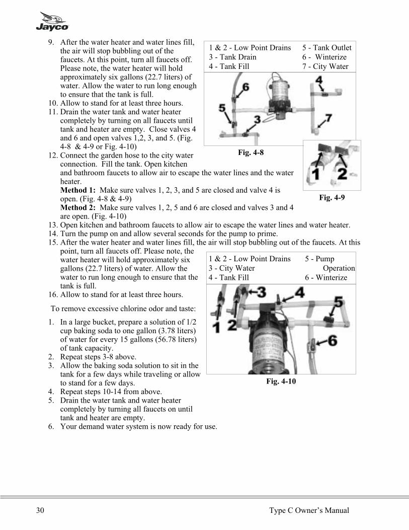
9. After the water heater and water lines fill,the air will stop bubbling out of thefaucets. At this point, turn all faucets off.Please note, the water heater will holdapproximately six gallons (22.7 liters) ofwater. Allow the water to run long enoughto ensure that the tank is full.
10. Allow to stand for at least three hours.11. Drain the water tank and water heater
completely by turning on all faucets untiltank and heater are empty. Close valves 4and 6 and open valves 1,2, 3, and 5. (Fig.4-8 & 4-9 or Fig. 4-10)
12. Connect the garden hose to the city waterconnection. Fill the tank. Open kitchenand bathroom faucets to allow air to escape the water lines and the waterheater.Method 1: Make sure valves 1, 2, 3, and 5 are closed and valve 4 isopen. (Fig. 4-8 & 4-9)Method 2: Make sure valves 1, 2, 5 and 6 are closed and valves 3 and 4are open. (Fig. 4-10)
13. Open kitchen and bathroom faucets to allow air to escape the water lines and water heater.14. Turn the pump on and allow several seconds for the pump to prime.15. After the water heater and water lines fill, the air will stop bubbling out of the faucets. At this
point, turn all faucets off. Please note, thewater heater will hold approximately sixgallons (22.7 liters) of water. Allow thewater to run long enough to ensure that thetank is full.
16. Allow to stand for at least three hours.
To remove excessive chlorine odor and taste:
1. In a large bucket, prepare a solution of 1/2cup baking soda to one gallon (3.78 liters)of water for every 15 gallons (56.78 liters)of tank capacity.
2. Repeat steps 3-8 above.3. Allow the baking soda solution to sit in the
tank for a few days while traveling or allowto stand for a few days.
4. Repeat steps 10-14 from above.5. Drain the water tank and water heater
completely by turning all faucets on untiltank and heater are empty.
6. Your demand water system is now ready for use.
30 Type C Owner’s Manual
1 & 2 - Low Point Drains3 - City Water4 - Tank Fill
5 - PumpOperation
6 - Winterize
Fig. 4-10
1 & 2 - Low Point Drains3 - Tank Drain4 - Tank Fill
5 - Tank Outlet6 - Winterize7 - City Water
Fig. 4-8
Fig. 4-9

FULL BASEMENT MODELS:
1. Drain the water tank and water heater completely by turning all faucets on until tank andheater are empty.
2. In a large bucket prepare a chlorine solution using 3/4 cup of household bleach and three (3)gallons (11.35 liters) of water.
3. Place the "Clear Hose" in a bucket of solution. (Fig. 4-11A)4. Turn "Fresh Water Valve" to normal position. (Fig. 4-11B)5. Turn "Winterizing Valve" to "Sanitize/Winterize Intake." (Fig. 4-11C)6. Close the "Water System Valve" (Fig. 4-12A) located behind the water pump. (Fig. 4-12B)7. Open the "Bypass Hose Valve." (Fig. 4-12C)8. Close the "Low Point Drain Valve."9. Turn the "Water Pump Switch" to the "ON" position and allow all of the chlorine solution to
enter the tank. (Fig. 4-11D)10. Open all (2 to 4 depending on the model of your unit) low-point drains. (Fig. 4-9 & 4-10)11. Turn “Fresh Water Inlet Valve” to fill water tank position.12. Open the “Water System Valve.” (Fig. 4-12A)13. Close the “Bypass Hose Valve.” (Fig. 4-12C)14. Connect garden hose to the “Fresh Water Inlet” and add water until the tank is 1/2 - 3/4 full.
(Fig. 4-11E)15. If possible, drive the vehicle to allow the solution to agitate in the tank.16. Fill the remainder of the tank with water. Open kitchen and bathroom faucets to allow air to
escape the water lines and the water heater.17. Turn the “Water Pump Switch” to the “ON” position and allow several seconds for the pump
to prime. (Fig. 4-11D)18. After the water heater and water lines fill, the air will stop bubbling out of the faucets. At
this point, turn all faucets off. Please note, the water heater will hold approximately sixgallons (22.7 liters) of water. Allow the water to run long enough to ensure that the tank isfull.
19. Allow to stand for at least three hours.20. Drain the water tank and water heater completely by turning on all faucets until tank and
heater are empty.21. Connect the garden how to the “Fresh Water Inlet” and fill the tank. (Fig. 4-10E)22. Open the kitchen and bathroom faucets to allow air to escape the water lines and the water
heater.23. Turn the “Water Pump Switch” to the “ON” position and allow several seconds for the pump
to prime. (Fig. 4-11D)24. After the water heater and water lines fill, the air will stop bubbling out of the faucets. At
this point, turn all faucets off. Please note, the water heater will hold approximately sixgallons of water. Allow the water to run long enough to ensure that the tank is full.
The Systems 31
Fig. 4-11 Fig. 4-12
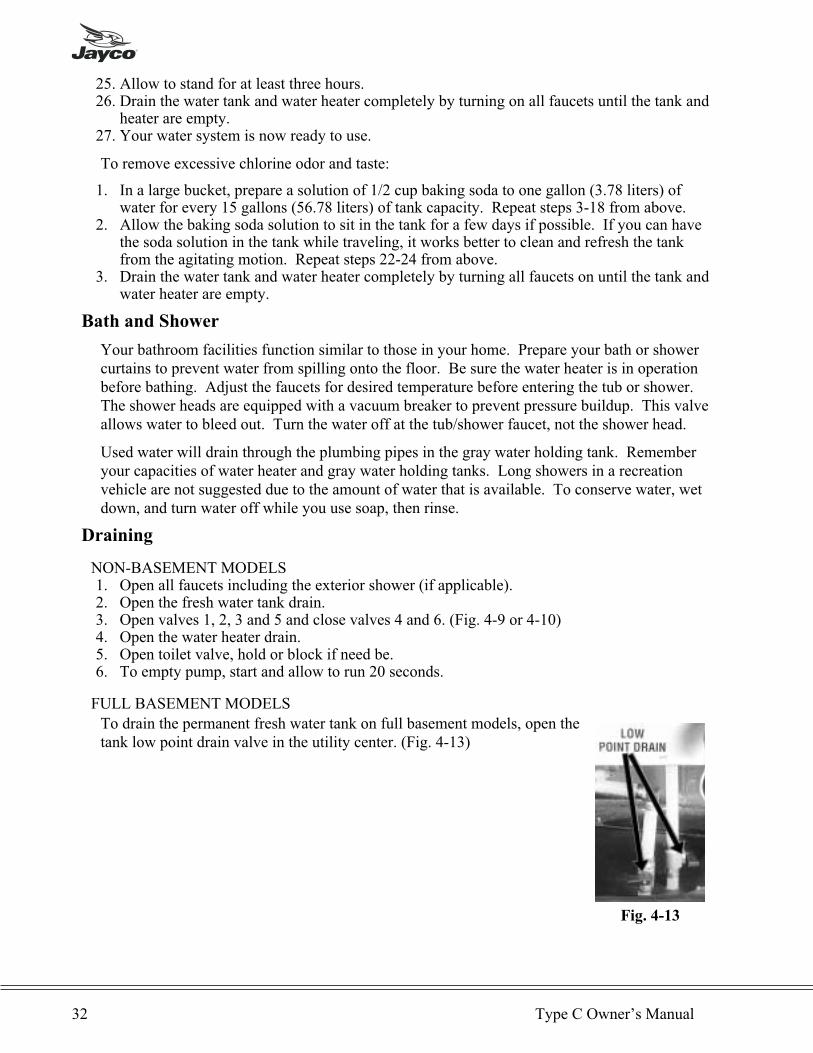
25. Allow to stand for at least three hours.26. Drain the water tank and water heater completely by turning on all faucets until the tank and
heater are empty.27. Your water system is now ready to use.
To remove excessive chlorine odor and taste:
1. In a large bucket, prepare a solution of 1/2 cup baking soda to one gallon (3.78 liters) ofwater for every 15 gallons (56.78 liters) of tank capacity. Repeat steps 3-18 from above.
2. Allow the baking soda solution to sit in the tank for a few days if possible. If you can havethe soda solution in the tank while traveling, it works better to clean and refresh the tankfrom the agitating motion. Repeat steps 22-24 from above.
3. Drain the water tank and water heater completely by turning all faucets on until the tank andwater heater are empty.
Bath and Shower
Your bathroom facilities function similar to those in your home. Prepare your bath or showercurtains to prevent water from spilling onto the floor. Be sure the water heater is in operationbefore bathing. Adjust the faucets for desired temperature before entering the tub or shower.The shower heads are equipped with a vacuum breaker to prevent pressure buildup. This valveallows water to bleed out. Turn the water off at the tub/shower faucet, not the shower head.
Used water will drain through the plumbing pipes in the gray water holding tank. Rememberyour capacities of water heater and gray water holding tanks. Long showers in a recreationvehicle are not suggested due to the amount of water that is available. To conserve water, wetdown, and turn water off while you use soap, then rinse.
Draining
NON-BASEMENT MODELS1. Open all faucets including the exterior shower (if applicable).2. Open the fresh water tank drain.3. Open valves 1, 2, 3 and 5 and close valves 4 and 6. (Fig. 4-9 or 4-10)4. Open the water heater drain.5. Open toilet valve, hold or block if need be.6. To empty pump, start and allow to run 20 seconds.
FULL BASEMENT MODELS
To drain the permanent fresh water tank on full basement models, open thetank low point drain valve in the utility center. (Fig. 4-13)
32 Type C Owner’s Manual
Fig. 4-13

SANITATION SYSTEM
Toilets
Two types or models of toilets are used on Jayco. One is the Starlight/Galaxy model featuringtwo foot pedals for flushing. The second type, the Aqua Magic 4, features two levers on theback side to flush the toilet.
OPERATING INSTRUCTIONS - STARLIGHT/GALAXY
Your toilet is efficient and easy to operate. Prior toutilizing the vehicle or after dumping your holdingtank, add the proper amount of deodorant to tank.Adding a deodorant will help control waste odors inthe tank. Thetford offers a complete line ofdeodorants and other convenience products. Aftereach use, the bowl fills with water automatically toa depth of two inches (50 mm). To add additionalwater to bowl, step on the small pedal (Fig. 4-14)and hold until the desired amount of water is in the bowl. Release pedal slowly. To flush, stepon the large pedal (Fig. 4-15) until rinse clears the toilet bowl, release pedal slowly.
OPERATING INSTRUCTIONS - AQUA MAGIC 4
The Aqua Magic 4 (Fig. 4-16)is equipped with two operating leverslocated on the right side of the toilet when facing the unit. To flush, pullthe black lever (Fig. 4-19) forward (clockwise) until rinse clears bowl andrelease lever slowly. Movement of the flush lever opens the waste valveand allows waste to pass into the holding tank. Water fill is activatedsimultaneously with the black flush lever. The lever should be held openfor several seconds to allow adequate flush water coverage of bowl todevelop. The white water fill lever (Fig. 4-18) can be operatedindependently of the black flush lever if more than the normal two inch (50 mm) automaticbowl refill water is desired. You must use an adequate amount of water when flushing toprevent solid waste build up and promote proper drainage. See Holding Tanks.
TOILET MAINTENANCE
See Chapter 6 for toilet maintenance.
The Systems 33
Fig. 4-14 Fig. 4-15
Fig. 4-16
Flushing lever (black) and
water fill lever (white)
shown in the normal closed
position. (Fig. 4-17)
Pull water fill lever (white)
to adjust to desired level.
(Fig. 4-18)
Single forward motion
flushes and refills bowl.
(Fig. 4-19)

Vents
Another important part of the sanitation system are the vents which release air from tanks. Eachtank has a vent pipe built into the through the cabinet, wall and roof. A vent cap is attached tothe roof and must be clear of obstructions to perform as intended. On some models the vent pipemay be part of the drainage system referred to as a "wet vent." This means water flowsdownward as air flows upward in the same pipe.
Holding Tanks
The final part of your system are the holding tanks. They hold waste and are located below thefloor of your. Bath tub and sinks drain into the waste water tank, also referred to as the "gray"water holding tank. The toilet drains into the sewage holding tank, also referred to as the wasteholding tank. Certain floor plans may also have the lavatory draining into the waste (sewage)tank.
USING TOILET AND TANK SYSTEM
NOTE: For added convenience and better sanitation system performance, it is advisableto always have four to six inches of water in the toilet.
Prior to using the sanitation system, it is strongly recommended to flush the toilet several
times and release sufficient water into the tank. If there is not a sufficient amount of water
used during flushing, waste materials may not evacuate properly from the drain line to the
tank. A clogged tank and pipes could eventually occur. When camping you should alwayshave four to six inches (10-15 cm) of water in the toilet bowl. The toilet system will performbetter when water is run for ten to fifteen seconds after flushing to ensure wastes will proceed tothe bottom of the tank. Unlike your toilet at home which uses four to seven gallons (15 to 30liters) per flush, the average recreation vehicle system uses one to three quarts (1 to 3 liters). Ifthere is not a sufficient amount of water used during flushing, waste materials may not evacuateproperly from drain line to tank. Clogged tank and pipes could eventually occur.
When hooking up to the sewer drain line in a campground, keep the termination valve on thewaste tank CLOSED until tank is at least 3/4 full. This will provide sufficient water to assist incomplete draining of the tank. At this time, open the termination valve to empty the tank andclose the valve when the tank is empty. Repeat this process as needed, but NEVER leave thetermination valve open when hooked up to the park's sewer system.
SEWAGE TANK PREPARATION1. Release one to two quarts (.95 to 1.89 liters) of water into the toilet bowl.2. Following the directions on your toilet chemical bottle by placing the recommended quantity
of holding tank chemical into the bowl.3. Flush the toilet and allow at least two gallons (7.57 liters) of water to flow into the tank.
� CAUTION: It is important to add enough water to prevent solid waste build up. Followthese directions each time after emptying your holding tank, except when winterizing.
34 Type C Owner’s Manual
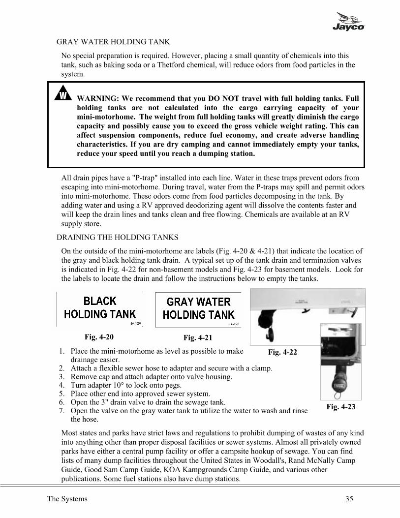
GRAY WATER HOLDING TANK
No special preparation is required. However, placing a small quantity of chemicals into thistank, such as baking soda or a Thetford chemical, will reduce odors from food particles in thesystem.
� WARNING: We recommend that you DO NOT travel with full holding tanks. Full
holding tanks are not calculated into the cargo carrying capacity of your
mini-motorhome. The weight from full holding tanks will greatly diminish the cargo
capacity and possibly cause you to exceed the gross vehicle weight rating. This can
affect suspension components, reduce fuel economy, and create adverse handling
characteristics. If you are dry camping and cannot immediately empty your tanks,
reduce your speed until you reach a dumping station.
All drain pipes have a "P-trap" installed into each line. Water in these traps prevent odors fromescaping into mini-motorhome. During travel, water from the P-traps may spill and permit odorsinto mini-motorhome. These odors come from food particles decomposing in the tank. Byadding water and using a RV approved deodorizing agent will dissolve the contents faster andwill keep the drain lines and tanks clean and free flowing. Chemicals are available at an RVsupply store.
DRAINING THE HOLDING TANKS
On the outside of the mini-motorhome are labels (Fig. 4-20 & 4-21) that indicate the location ofthe gray and black holding tank drain. A typical set up of the tank drain and termination valvesis indicated in Fig. 4-22 for non-basement models and Fig. 4-23 for basement models. Look forthe labels to locate the drain and follow the instructions below to empty the tanks.
1. Place the mini-motorhome as level as possible to makedrainage easier.
2. Attach a flexible sewer hose to adapter and secure with a clamp.3. Remove cap and attach adapter onto valve housing.4. Turn adapter 10° to lock onto pegs.5. Place other end into approved sewer system.6. Open the 3" drain valve to drain the sewage tank.7. Open the valve on the gray water tank to utilize the water to wash and rinse
the hose.
Most states and parks have strict laws and regulations to prohibit dumping of wastes of any kindinto anything other than proper disposal facilities or sewer systems. Almost all privately ownedparks have either a central pump facility or offer a campsite hookup of sewage. You can findlists of many dump facilities throughout the United States in Woodall's, Rand McNally CampGuide, Good Sam Camp Guide, KOA Kampgrounds Camp Guide, and various otherpublications. Some fuel stations also have dump stations.
The Systems 35
Fig. 4-20 Fig. 4-21
Fig. 4-22
Fig. 4-23

WINTERIZING YOUR MINI-MOTORHOME
Preparing your recreation vehicle for winter is very important for most states and Canada.Failure to prepare the will cause supply lines and water heater to freeze causing breakage.Repairs due to freezing are not to be covered under the terms of your Jayco Limited Warranty.
� WARNING: Do not use Ethylene Glycol (automotive antifreeze) or Methanol
(windshield washer antifreeze) in your fresh water system. They are harmful and may
be fatal if swallowed.
Non-Basement Models
Two methods of winterizing your mini-motorhome after draining and flushing the system arelisted below.
USING AIR PRESSURE1. Run the pump until dry, about fifteen seconds.2. Make sure the valves are set in one of the following ways:
Method 1: Close all the valves. (Fig. 4-2 & 4-3)Method 2: Close valves 1, 2 and 3. Open valves 4, 5 and 6. (Fig. 4-4)
� CAUTION: If the above step is not followed, air pressure will fill the potable water tankwhich could cause serious damage to the tank.
3. Using an air hose and adapter, blow air through the city water fill. (Fig. 4-1)4. Leave the faucets, drains and toilets open. Any remaining water will blow out in five to ten
minutes.5. Pour one cup of non-toxic RV antifreeze into all drain P-traps.
USING THE WATER HEATER BYPASS
The water heater bypass is available on most vehicles.
1. Turn off the pump.2. Make sure the valves are set in one of the following ways:
Method 1: Close valves 1, 2, 3, 4 and 5 and open valve 6. (Fig. 4-2 & 4-3)Method 2: Close valves 1, 2, 4 and 5 and open valves 3 and 6. (Fig. 4-4)
3. Drain the water heater (Consult the water heater owner's manual for details.) and fresh watertank.
4. Put the clear hose into a jug of non-toxic RV antifreeze. You will need more than one gallonof antifreeze.
5. Turn on the pump and open each faucet until the antifreeze flows through. Do not forget torun the antifreeze through the toilet.
6. Pour at least one cup of antifreeze into each drain to protect the P-traps.7. Before using the water system again, drain (see the draining instructions in this chapter) and
flush the water system. Sanitize (see the sanitizing instructions in this chapter) and flush thewhole system. It is now ready for use.
36 Type C Owner’s Manual
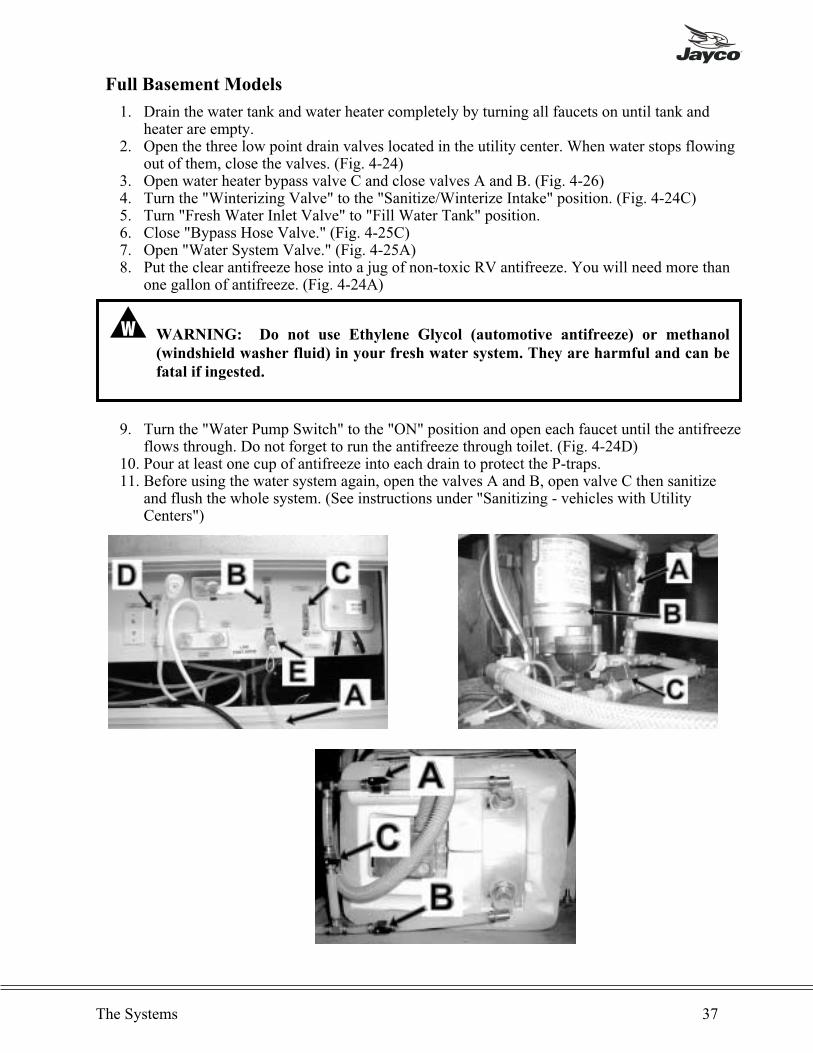
Full Basement Models
1. Drain the water tank and water heater completely by turning all faucets on until tank andheater are empty.
2. Open the three low point drain valves located in the utility center. When water stops flowingout of them, close the valves. (Fig. 4-24)
3. Open water heater bypass valve C and close valves A and B. (Fig. 4-26)4. Turn the "Winterizing Valve" to the "Sanitize/Winterize Intake" position. (Fig. 4-24C)5. Turn "Fresh Water Inlet Valve" to "Fill Water Tank" position.6. Close "Bypass Hose Valve." (Fig. 4-25C)7. Open "Water System Valve." (Fig. 4-25A)8. Put the clear antifreeze hose into a jug of non-toxic RV antifreeze. You will need more than
one gallon of antifreeze. (Fig. 4-24A)
� WARNING: Do not use Ethylene Glycol (automotive antifreeze) or methanol
(windshield washer fluid) in your fresh water system. They are harmful and can be
fatal if ingested.
9. Turn the "Water Pump Switch" to the "ON" position and open each faucet until the antifreezeflows through. Do not forget to run the antifreeze through toilet. (Fig. 4-24D)
10. Pour at least one cup of antifreeze into each drain to protect the P-traps.11. Before using the water system again, open the valves A and B, open valve C then sanitize
and flush the whole system. (See instructions under "Sanitizing - vehicles with UtilityCenters")
The Systems 37

USING THE WATER SYSTEM DURING FREEZING WEATHER
Please keep in mind that your mini-motorhome was not designed for use during sub-freezingweather.
There is no commodity or product that can be added to the fresh water systems to ensure freezeprotection while the system is in use, other than RV antifreeze. Do not drink water withantifreeze. This includes non-toxic RV antifreeze.
38 Type C Owner’s Manual
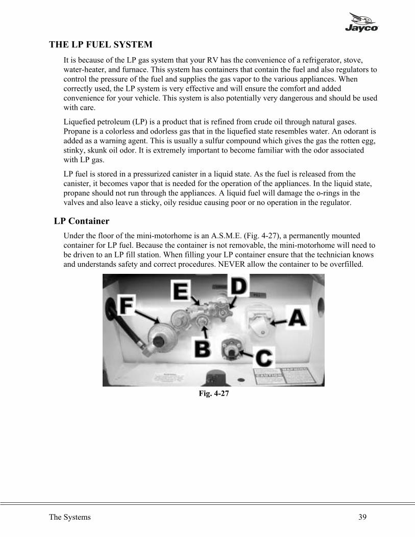
THE LP FUEL SYSTEM
It is because of the LP gas system that your RV has the convenience of a refrigerator, stove,water-heater, and furnace. This system has containers that contain the fuel and also regulators tocontrol the pressure of the fuel and supplies the gas vapor to the various appliances. Whencorrectly used, the LP system is very effective and will ensure the comfort and addedconvenience for your vehicle. This system is also potentially very dangerous and should be usedwith care.
Liquefied petroleum (LP) is a product that is refined from crude oil through natural gases.Propane is a colorless and odorless gas that in the liquefied state resembles water. An odorant isadded as a warning agent. This is usually a sulfur compound which gives the gas the rotten egg,stinky, skunk oil odor. It is extremely important to become familiar with the odor associatedwith LP gas.
LP fuel is stored in a pressurized canister in a liquid state. As the fuel is released from thecanister, it becomes vapor that is needed for the operation of the appliances. In the liquid state,propane should not run through the appliances. A liquid fuel will damage the o-rings in thevalves and also leave a sticky, oily residue causing poor or no operation in the regulator.
LP Container
Under the floor of the mini-motorhome is an A.S.M.E. (Fig. 4-27), a permanently mountedcontainer for LP fuel. Because the container is not removable, the mini-motorhome will need tobe driven to an LP fill station. When filling your LP container ensure that the technician knowsand understands safety and correct procedures. NEVER allow the container to be overfilled.
The Systems 39
Fig. 4-27
� CAUTION: DO NOT use tools or heavy equipment to open or close valves on thecontainers. HAND TIGHTEN only.
There are four components attached to the container for filling and dispensing the fuel (Fig.4-27):
1. Gas Fill Valve (A): attach the fill hose before opening valve. Unless you are filling thecontainer, keep the cap on at all times.
2. Relief Valve (B): open only during filling process. When open, it releases air and serves asan 80% full indicator.
3. LP Gauge (C): indicates quantity of fuel in container.4. Outage Valve (D): dispenses fuel through the LP gas system to appliances for usage.
When LP gas containers are filled to 80% level, there is available space for safe expansion ofthe vaporized liquid. If the tank becomes overfilled it may gain pressure due to exposure todirect sunlight and will begin "blowing off" pressure from the relief valve. This can be detectedby the strong odor around tanks. Keep open flames away from this area.
� WARNING: Your vehicle has exterior combustion air inlets. Appliance pilot lights
and their ignitors should be turned off during gasoline or LP gas refueling. (Required
by law in some states.)
A warning label has been located near the LP gas container. This label reads:
� WARNING: Do not fill container(s) to more than 80 percent of capacity. Overfilling
the LP gas container can result in uncontrolled gas flow which may cause a fire or an
explosion. A properly filled container will contain approximately 80 percent of its
volume as liquid LP gas.
40 Type C Owner’s Manual
This gas piping system is designed for use of liquefiedpetroleum gas only. Do not connect natural gas to thissystem. Do not fill container(s) to more than 80 percent ofcapacity. Securely cap inlet(s) when not connected for use.After turning on gas, except after normal containerreplacement, test gas piping and connections to appliancesfor leakage with soapy water or bubble solution. Do not useproducts that contain ammonia or chlorine. AD-34
ALL GAS LINES HAVE BEEN CHECKED WITH
AIR PRESSURE. DEALERS ARE REQUIRED TO
RECHECK AND ADJUST PRESSURE BEFORE
DELIVERY TO CUSTOMERS.
� WARNING: LP gas containers should not be placed or stored inside the vehicle. LP
gas containers are equipped with safety devices that relieve excess pressure by
discharging gas into the atmosphere. Do not bring or store LP gas containers, gasoline
or other flammable liquids inside the recreation vehicle. Disregarding this warning
may result in fires or explosions.
� WARNING: Never smoke while filling the LP tanks. Keep the RV away from
immediate filling area when possible or extinguish all gas pilot lights.
When an LP tank is low, occasionally there is a concentration of garlic-like odor which may bemistaken for a gas leak. After a change over to a full tank, the odor usually will disappear. Ifnot, turn off the valve of the LP container and have the system checked by a qualifiedtechnician.
Fuel Distribution Components
� CAUTION: Remember - POL adapters and fittings have left hand threads.
POL ADAPTER AND LOW PRESSURE
Propane leaves the container through a POL adapter (Fig. 4-27E) with an excess flow valvebuilt into adaptor, which is attached to the regulator. No sealant is required on a brass to brassconnection. The excess flow valve provides a large volume of propane to escape from the bottleshould there be a breakage between the container and regulator.
REGULATOR
The regulator (Fig. 4-27F) is the heart of your LP gas system and has internal moving parts. Itsfunction is to reduce high and varied pressure from the LP container to a safe and consistent lowpressure. The inlet valve is the first stage, reducing container pressure to ten to thirteen pounds.The second stage will reduce the gas from ten pounds to an operating pressure of 11" W.C.(water column) or 6.35 oz. of outlet pressure to the mini-motorhome system. The second stageis adjustable and will need to be adjusted for precise operation. DO NOT attempt to adjustregulator. Have an authorized and competent technician make any adjustments. We suggest thisnormal maintenance procedure be performed once per year.
� WARNING: LP gas regulators must always be installed with the diaphragm vent
facing downward. Regulators that are not in a compartment have been equipped with
a protective cover. Ensure that the regulator vent faces downward and that the cover
is in place. This will minimize vent blockage that could result in excessive gas pressure
causing a fire or an explosion.
The Systems 41
If traveling on wet roads and in freezing weather conditions, ensure that the LP gas regulator isprotected from road spray. If water enters the vent in the regulator, it may freeze the pressurecontrolling diaphragm in the open position so that the container pressure is applied to theappliances - a hazardous condition. Follow the instruction given by the manufacturer of theregulator. The vent on the regulator is to be turned downward between the 5 and 7 o'clockposition.
MAIN SUPPLY HOSE
The main supply hose will be attached from the regulator to the brass manifold fitting in theframe of the mini-motorhome. The swivel brass nut on the main hose is the final attachment.
OPERATION
After the camper is completely set up and you are prepared for camping enjoyment, follow thesesteps for LP gas operation.
1. Close all burner valves, controls and pilot light valves.2. Open main valve on LP container slowly to avoid fast rush of propane vapor through excess
flow valve causing "gas freeze." Should you experience a gas "freeze-up," close main valveand wait 15 minutes before trying again.
3. Listen carefully as gas begins to flow. If hissing is heard for more than one or two seconds,close valve and search for leak. (See instructions below.)
4. Light appliances as needed and directed in appliance chapter.
Keep container valve(s) closed when traveling. Some states prohibit traveling with LPcontainer, especially in underground tunnels on expressways.
� WARNING: Portable fuel-burning equipment, including wood and charcoal grills
and stoves, shall not be used inside the recreation vehicle. The use of this equipment
inside the recreation vehicle may cause fires or asphyxiation.
When an LP tank gets low, sometimes there is a concentration of garlic-like odor which may bemistaken for a gas leak. After a change over to a full tank, the odor usually will disappear. Ifnot, turn off the LP and have the system checked by a qualified technician.
Checking for Leaks
Upon delivery and periodically thereafter, check your gas system for possible leaks. Althoughthe entire distribution system and its attached appliances have undergone factory testing forleaks, the camper is subject to road vibrations, which can cause connections and fittings todevelop leaks. If you do encounter this odor, turn off all open flames immediately and begin asystematic search for leaks throughout the gas system. Use a bubble solution of soapy water,without ammonia or chlorine content, on connections and fittings. (NEVER USE A MATCH tocheck for leaks.) Bubbles will appear at the leaky points. When tightening connections, use twowrenches with opposing torque to prevent twisting of copper tubing. If the leak doesn't show upin the manifold or copper tubing distribution systems, check the appliances.
42 Type C Owner’s Manual
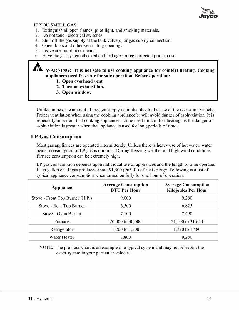
IF YOU SMELL GAS1. Extinguish all open flames, pilot light, and smoking materials.2. Do not touch electrical switches.3. Shut off the gas supply at the tank valve(s) or gas supply connection.4. Open doors and other ventilating openings.5. Leave area until odor clears.6. Have the gas system checked and leakage source corrected prior to use.
� WARNING: It is not safe to use cooking appliance for comfort heating. Cooking
appliances need fresh air for safe operation. Before operation:
1. Open overhead vent.
2. Turn on exhaust fan.
3. Open window.
Unlike homes, the amount of oxygen supply is limited due to the size of the recreation vehicle.Proper ventilation when using the cooking appliance(s) will avoid danger of asphyxiation. It isespecially important that cooking appliances not be used for comfort heating, as the danger ofasphyxiation is greater when the appliance is used for long periods of time.
LP Gas Consumption
Most gas appliances are operated intermittently. Unless there is heavy use of hot water, waterheater consumption of LP gas is minimal. During freezing weather and high wind conditions,furnace consumption can be extremely high.
LP gas consumption depends upon individual use of appliances and the length of time operated.Each gallon of LP gas produces about 91,500 (96530 ) of heat energy. Following is a list oftypical appliance consumption when turned on fully for one hour of operation:
ApplianceAverage Consumption
BTU Per Hour
Average Consumption
Kilojoules Per Hour
Stove - Front Top Burner (H.P.) 9,000 9,280
Stove - Rear Top Burner 6,500 6,825
Stove - Oven Burner 7,100 7,490
Furnace 20,000 to 30,000 21,100 to 31,650
Refrigerator 1,200 to 1,500 1,270 to 1,580
Water Heater 8,800 9,280
NOTE: The previous chart is an example of a typical system and may not represent theexact system in your particular vehicle.
The Systems 43
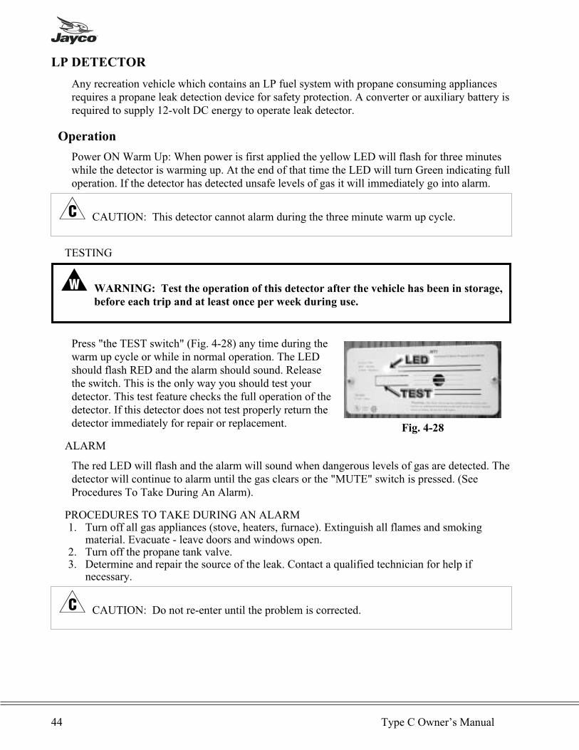
LP DETECTOR
Any recreation vehicle which contains an LP fuel system with propane consuming appliancesrequires a propane leak detection device for safety protection. A converter or auxiliary battery isrequired to supply 12-volt DC energy to operate leak detector.
Operation
Power ON Warm Up: When power is first applied the yellow LED will flash for three minuteswhile the detector is warming up. At the end of that time the LED will turn Green indicating fulloperation. If the detector has detected unsafe levels of gas it will immediately go into alarm.
� CAUTION: This detector cannot alarm during the three minute warm up cycle.
TESTING
� WARNING: Test the operation of this detector after the vehicle has been in storage,
before each trip and at least once per week during use.
Press "the TEST switch" (Fig. 4-28) any time during thewarm up cycle or while in normal operation. The LEDshould flash RED and the alarm should sound. Releasethe switch. This is the only way you should test yourdetector. This test feature checks the full operation of thedetector. If this detector does not test properly return thedetector immediately for repair or replacement.
ALARM
The red LED will flash and the alarm will sound when dangerous levels of gas are detected. Thedetector will continue to alarm until the gas clears or the "MUTE" switch is pressed. (SeeProcedures To Take During An Alarm).
PROCEDURES TO TAKE DURING AN ALARM1. Turn off all gas appliances (stove, heaters, furnace). Extinguish all flames and smoking
material. Evacuate - leave doors and windows open.2. Turn off the propane tank valve.3. Determine and repair the source of the leak. Contact a qualified technician for help if
necessary.
� CAUTION: Do not re-enter until the problem is corrected.
44 Type C Owner’s Manual
Fig. 4-28

ALARMMUTE
This feature is activated by pressing the TEST/MUTE button when the detector is in alarm.
1. The red LED will continue to flash and the alarm will beep every thirty seconds until the gaslevel has dropped to a safe level.
2. The LED will flash green until the end of the mute cycle.3. If dangerous gas levels return before the end of the mute cycle, the alarm will beep four times
and return to #1.4. After two minutes, the detector will return to normal operation (solid green) or resound the
alarm if dangerous levels of gas remain in the area.
Malfunction Alarm
The microprocessor will activate the malfunction alarm when it detects a fault in the detectorsoperation. The LED will alternately flash red and green, while the sounder beeps twice everyfifteen seconds. The mute switch will not function. Remove the detector immediately and returnit for repair or replacement.
Low Power Operation
This detector will operate normally down to 7-volt DC. Do not operate this detector below7-volt DC.
� WARNING: Limitations of propane/methane gas detectors:
• This detector will not work without power. Examples causing no power
are: an open circuit breaker, a faulty power line connection, a blown or
missing fuse.
• This detector will only indicate the presence of propane or methane gas at
the sensor. Explosive gas may be present in other areas.
• This detector may not be heard. The alarm loudness is designed to meet or
exceed regulatory standards, however, the alarm may not be heard if
detectors are located in remote locations or behind closed doors. The alarm
may not be heard by persons who are hard of hearing.
• This detector is not a smoke or fire detector. It is not suitable as a smoke or
fire detector.
• This detector is not suitable for installation in hazardous areas as defined
in the national electrical code.
Additional information is supplied in a manual published by the manufacturer of this equipment.
The Systems 45
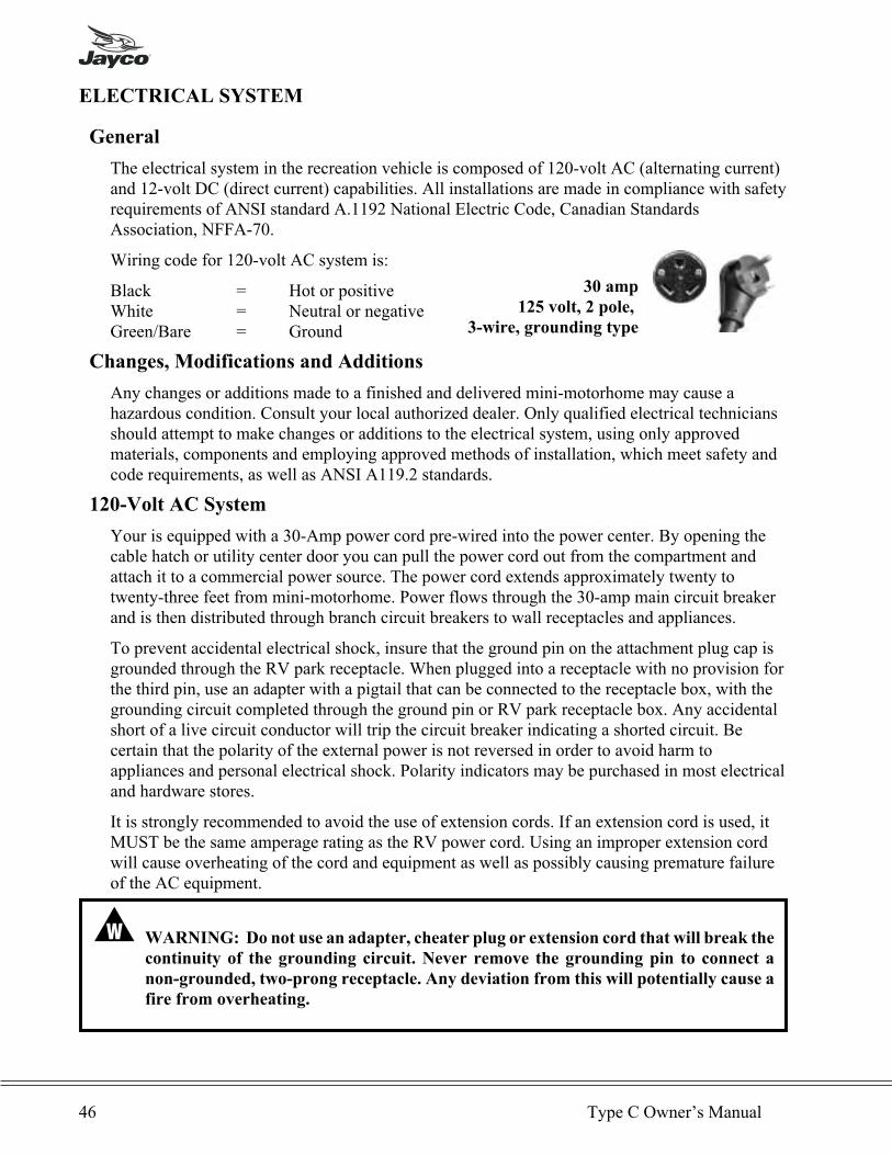
ELECTRICAL SYSTEM
General
The electrical system in the recreation vehicle is composed of 120-volt AC (alternating current)and 12-volt DC (direct current) capabilities. All installations are made in compliance with safetyrequirements of ANSI standard A.1192 National Electric Code, Canadian StandardsAssociation, NFFA-70.
Wiring code for 120-volt AC system is:
Black = Hot or positiveWhite = Neutral or negativeGreen/Bare = Ground
Changes, Modifications and Additions
Any changes or additions made to a finished and delivered mini-motorhome may cause ahazardous condition. Consult your local authorized dealer. Only qualified electrical techniciansshould attempt to make changes or additions to the electrical system, using only approvedmaterials, components and employing approved methods of installation, which meet safety andcode requirements, as well as ANSI A119.2 standards.
120-Volt AC System
Your is equipped with a 30-Amp power cord pre-wired into the power center. By opening thecable hatch or utility center door you can pull the power cord out from the compartment andattach it to a commercial power source. The power cord extends approximately twenty totwenty-three feet from mini-motorhome. Power flows through the 30-amp main circuit breakerand is then distributed through branch circuit breakers to wall receptacles and appliances.
To prevent accidental electrical shock, insure that the ground pin on the attachment plug cap isgrounded through the RV park receptacle. When plugged into a receptacle with no provision forthe third pin, use an adapter with a pigtail that can be connected to the receptacle box, with thegrounding circuit completed through the ground pin or RV park receptacle box. Any accidentalshort of a live circuit conductor will trip the circuit breaker indicating a shorted circuit. Becertain that the polarity of the external power is not reversed in order to avoid harm toappliances and personal electrical shock. Polarity indicators may be purchased in most electricaland hardware stores.
It is strongly recommended to avoid the use of extension cords. If an extension cord is used, itMUST be the same amperage rating as the RV power cord. Using an improper extension cordwill cause overheating of the cord and equipment as well as possibly causing premature failureof the AC equipment.
� WARNING: Do not use an adapter, cheater plug or extension cord that will break the
continuity of the grounding circuit. Never remove the grounding pin to connect a
non-grounded, two-prong receptacle. Any deviation from this will potentially cause a
fire from overheating.
46 Type C Owner’s Manual
30 amp
125 volt, 2 pole,
3-wire, grounding type
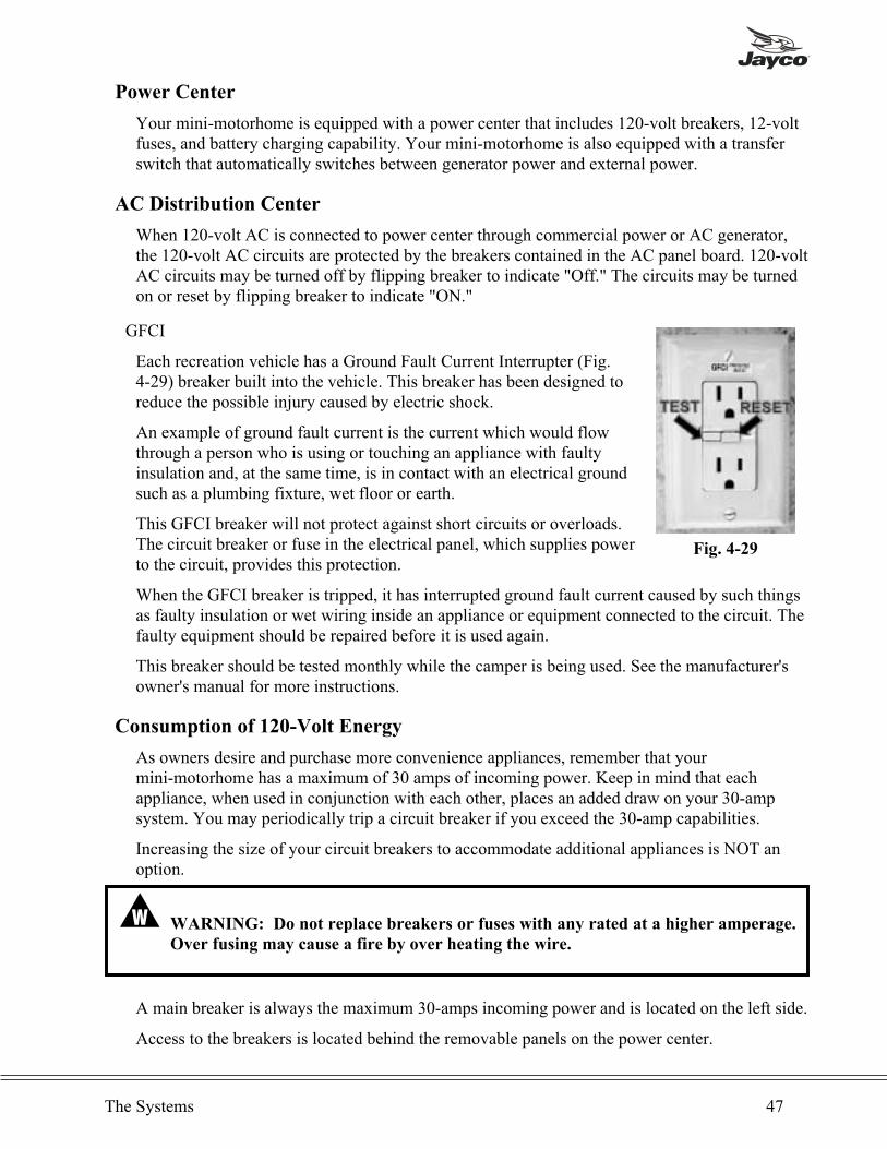
Power Center
Your mini-motorhome is equipped with a power center that includes 120-volt breakers, 12-voltfuses, and battery charging capability. Your mini-motorhome is also equipped with a transferswitch that automatically switches between generator power and external power.
AC Distribution Center
When 120-volt AC is connected to power center through commercial power or AC generator,the 120-volt AC circuits are protected by the breakers contained in the AC panel board. 120-voltAC circuits may be turned off by flipping breaker to indicate "Off." The circuits may be turnedon or reset by flipping breaker to indicate "ON."
GFCI
Each recreation vehicle has a Ground Fault Current Interrupter (Fig.4-29) breaker built into the vehicle. This breaker has been designed toreduce the possible injury caused by electric shock.
An example of ground fault current is the current which would flowthrough a person who is using or touching an appliance with faultyinsulation and, at the same time, is in contact with an electrical groundsuch as a plumbing fixture, wet floor or earth.
This GFCI breaker will not protect against short circuits or overloads.The circuit breaker or fuse in the electrical panel, which supplies powerto the circuit, provides this protection.
When the GFCI breaker is tripped, it has interrupted ground fault current caused by such thingsas faulty insulation or wet wiring inside an appliance or equipment connected to the circuit. Thefaulty equipment should be repaired before it is used again.
This breaker should be tested monthly while the camper is being used. See the manufacturer'sowner's manual for more instructions.
Consumption of 120-Volt Energy
As owners desire and purchase more convenience appliances, remember that yourmini-motorhome has a maximum of 30 amps of incoming power. Keep in mind that eachappliance, when used in conjunction with each other, places an added draw on your 30-ampsystem. You may periodically trip a circuit breaker if you exceed the 30-amp capabilities.
Increasing the size of your circuit breakers to accommodate additional appliances is NOT anoption.
� WARNING: Do not replace breakers or fuses with any rated at a higher amperage.
Over fusing may cause a fire by over heating the wire.
A main breaker is always the maximum 30-amps incoming power and is located on the left side.
Access to the breakers is located behind the removable panels on the power center.
The Systems 47
Fig. 4-29

120-VOLT AC
The diagram below for the 120-volt AC layout.
12-VOLT DC
See the above diagram for fuse definitions.
� CAUTION: Your recreation vehicle has many 12-volt DC loads. When combined, theirtotal is more power consumption than the power converter can produce. Periodic overloadscan be handled with an auxiliary battery for limited periods of time. Prolonged overload on aconverter will shorten the life of its components. It is recommended to plan and conserve theusage of your 12-volt DC system in a priority method.
48 Type C Owner’s Manual
1 - Bath2 - Pump3 - Furnace/Refrigerator4 - Bed Lights5 - TV/Radio6 - Ceiling Lights
7 - Optional8 - Slideout Lights9 - Optional10 - Optional11 - Optional12 - Power for Slideout
A - MainB - Converter/UtilityC - Air Conditioner
D - Kitchen, Bath, OutsideE - MicrowaveF - Electric Water Heater
12-volt DC Layout
120-volt AC Layout
12-Volt DC (Direct Current) System
NOTE: Mini-motorhome master battery switch MUST be on before any 12 volt devicewill operate.
Included in your load center is a converter which transforms 120-volt AC energy into 12-voltDC energy to supply your mini-motorhome. When 120-volt AC power is supplied to the powercenter through the main circuit breaker in "ON" position, the converter will produce 12-volt DCpower to mini-motorhome as long as the auxiliary battery is properly connected.
Electric components are sensitive to heat and a converter will produce heat. Ventilation isrequired for proper operation. Also, a fan is built into the converter to assist air movement andtemperature control. If normal ventilation is obstructed and the fan is not able to control thetemperature, a protective "Thermal Breaker" will trip the 120-volt AC power to the converter.After the compartment cools down, the breaker will reset automatically and 12-volt power willbe restored through the converter.
Replaceable fuses are used to protect the 12-volt components. Blowing fuses continuouslyindicates the overloading of a circuit or a "shorted circuit." Should fuses continue to blow,contact your RV dealer for assistance.
A separate 12-volt fuse panel supplies power to your chassis. See chassis manual for assistance.
When 120 volt power is supplied to the converter through direct connection at the campsite, theconverter will supply 12 volt DC power to the auxiliary battery automatically.
The auxiliary battery will also receive a charge from alternator when the engine is running.
Batteries, Chassis and Auxiliary
Each mini-motorhome chassis is built with a battery to provide energy to start the engine andsupply energy for other components in the chassis. This battery is located under the hood. FordMotor Co. uses a "Motorcraft" battery, serviced and warranted by Ford.
An auxiliary battery is included in each mini-motorhome for storage power when 120-voltenergy is not available. When drawing energy from storage battery, remember there is limitedpower available until the battery needs to be recharged. This auxiliary battery is located in the"house portion" of your mini-motorhome.
All auxiliary batteries require an "in-line" fuse or a 12-volt breaker placed within 18" of batteryfor your protection.
Maintenance is a normal requirement on all batteries for maximum performance.
1. Keep all terminals clean and tight.2. Keep the battery filled with water as cells without water cannot hold a charge of energy. A
battery used in daily operation will consume water.3. The charging system must be in good operating condition to maintain your battery.
Preparation of battery(ies) for winter storage must be carefully considered, especially theauxiliary battery. Components attached to either battery will discharge the battery in one to threemonths. Discharged batteries are subject to freezing, breaking and permanent damage. If you arestoring your mini-motorhome for an extended period, it is important to charge the battery(ies)every thirty days to maintain a charged condition at 1.265 specific gravity. Disconnect and/or
The Systems 49

remove the battery to prevent minor amp draw. If removed, store the battery in a cool, dry placeand maintain charge. The positive cable must be protected from contacting metal surfaces.
� WARNING: If you replace or unhook your battery, ensure that the wires are
connected properly: Positive-Black; Negative-White.
Isolators
When an auxiliary or "house" battery is installed in a recreation vehicle, it's the nature ofparallel circuitry to draw energy from both batteries. A device called an "isolator" must beinstalled for two purposes. First it receives current from the alternator and controls distributionof energy to house and chassis batteries. Secondly, it serves as a check valve to prevent energyfrom being drawn from the tow vehicle chassis battery. Energy in the tow vehicle battery is nowpreserved and can be used to start your engine if needed.
The Jayco mini-motorhome has a solenoid located on the cowl of chassis under the hood.
Master Battery Switch
Located near the mini-motorhome entrance door there is a master battery switch. This masterbattery switch controls all 12 volt power supplied to the "house portion" of the mini-motorhome.This switch must be "ON" before any electrical current will be supplied to the appliances,outlets, and lights. During storage of your mini-motorhome, it is important to have this switch inthe "OFF" position.
NOTE: Make sure the master battery switch is in the "OFF” position during storage of themini-motorhome to avoid draining current from the battery.
Interior 12-Volt Components
Fig. 4-25 shows a drawing of the 12-volt DC distribution center of circuits. Your interior lights,furnace and other components will operate from terminals 1-4.
Auxiliary Start System
Your mini-motorhome can momentarily connect both batteries should the chassis batterybecome discharged for some reason. Press the button on the dash, located on the left side of thesteering column, and hold. Now use the ignition switch to start the engine. Release the buttonafter the engine has started.
Dome Lights for Cab
These lights are wired directly to the chassis wiring. Operation for these lights is the headlightswitch or the button switches located in the driver and passenger doors.
50 Type C Owner’s Manual
Exterior Lights
Signal, backup, clearance and tail lights are attached to the wire harness supplied by the chassismanufacturer as listed below. All exterior lights operate through the chassis fuse panel. Thesefuses as listed in your chassis manual.
Wiring Code
Ford
*Front clearance lights are hooked to a gray plug at the drivers side door post with brown wire.The white wire is grounded to the chassis frame at the step well.
Fuse Chart
All exterior light fuses are located in the chassis fuse block, located under the dash near theemergency brake pedal. The fuse chart below is for interior items built into the house portion ofthe vehicle by the recreation vehicle manufacturer. Some items are optional as listed.
� CAUTION: DO NOT install any replacement fuse with a higher rating than specifiedbelow.
ITEM AMP SIZE TYPE APPLICATION LOCATION
Remote Mirrors 1 Glass Option In line under dash
Heated Holding Tanks 15 Blade OptionIn mini-motorhome fuse
panel #5
Radio 3 Blade Option Behind radio
The Systems 51
RV Chassis
Green. . . . . . . . . . . . . . . . . . . . . . Brown/WhiteOrange. . . . . . . . . . . . . . . . . . . . . . . . . . YellowBrown . . . . . . . . . . . . . . . . . . . . . . Dark GreenYellow . . . . . . . . . . . . . . . . Black/Light GreenWhite. . . . . . . . . . . . . . . . . . . . . . . . . . . . WhiteBlack . . . . . . . . . . . . . . . . . . to 12-volt Breaker
CONNECTED AT: Left hand frame rail at rear.
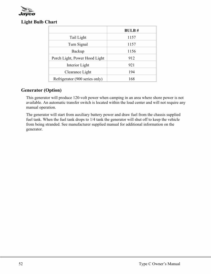
Light Bulb Chart
BULB #
Tail Light 1157
Turn Signal 1157
Backup 1156
Porch Light, Power Hood Light 912
Interior Light 921
Clearance Light 194
Refrigerator (900 series only) 168
Generator (Option)
This generator will produce 120-volt power when camping in an area where shore power is notavailable. An automatic transfer switch is located within the load center and will not require anymanual operation.
The generator will start from auxiliary battery power and draw fuel from the chassis suppliedfuel tank. When the fuel tank drops to 1/4 tank the generator will shut off to keep the vehiclefrom being stranded. See manufacturer supplied manual for additional information on thegenerator.
52 Type C Owner’s Manual
Chapter 5
APPLIANCES
GENERAL
� WARNING: If the manufacturer’s operation and care instructions are not followed
precisely, a fire or explosion may result causing property damage, personal injury or
loss of life.
All appliances in your Jayco recreation vehicle are name brand quality built equipment, guidedby current code and standards. For gas operation, the appliances in your mini-motorhome willoperate on LP gas only, not on natural gas. All safety precautions for LP gas from Chapter 4must be followed during operation of the appliances. Please familiarize yourself with thembefore proceeding.
This owner’s manual covers basic appliance operation only. Make sure you read all
manuals provided by the appliance manufacturer which are included with each recreation
vehicle. These manuals provide extensive information for your safety and the proper
operation of the appliances.
For Your Safety (Read Before Operating)
1. Prior to operation, smell the area around the appliances to ensure that gas has not settled onthe floor.
2. WHAT TO DO IF YOU SMELL GAS• Extinguish any open flames.• Evacuate all persons from the vehicle.• Shut off the gas supply at the gas container or source.• Do not touch any electrical switch or use phone or radio in the vehicle.• Do not start the vehicle’s engine or electric generator.• Contact the nearest gas supplier or qualified service technician for repairs.• If you cannot reach a gas supplier or qualified service technician, contact the nearest
fire department.• Do not turn on the gas supply until the gas leak(s) has been repaired.
3. Use only your hand to turn a gas control valve. Never use tools. If the valve will not turn byhand, do not try to repair it. Call a qualified service technician. Using force may result in afire or explosion.
4. Do not use the appliance if any part has become wet. Immediately call a qualified servicetechnician to inspect and replace any part of the control system and gas control which hasbeen under water.
5. Do not store or use combustible materials or liquids near or adjacent to any appliance.Appliances shall not be installed in any location where flammable liquids or vapors are likelyto be present.
6. Improper installation, adjustment, alteration, service or maintenance can cause propertydamage, personal injury or loss of life. Refer to installation instructions provided by themanufacturer or each appliance. Installation and service must be performed by a qualifiedinstaller, service center or gas supplier.
7. Shut off all gas appliances and pilot lights when refueling gasoline tanks, LP tanks, or whenvehicle is in motion.
Appliances 53
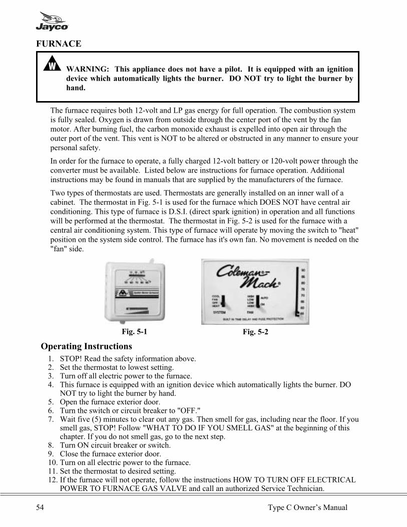
FURNACE
� WARNING: This appliance does not have a pilot. It is equipped with an ignition
device which automatically lights the burner. DO NOT try to light the burner by
hand.
The furnace requires both 12-volt and LP gas energy for full operation. The combustion systemis fully sealed. Oxygen is drawn from outside through the center port of the vent by the fanmotor. After burning fuel, the carbon monoxide exhaust is expelled into open air through theouter port of the vent. This vent is NOT to be altered or obstructed in any manner to ensure yourpersonal safety.
In order for the furnace to operate, a fully charged 12-volt battery or 120-volt power through theconverter must be available. Listed below are instructions for furnace operation. Additionalinstructions may be found in manuals that are supplied by the manufacturers of the furnace.
Two types of thermostats are used. Thermostats are generally installed on an inner wall of acabinet. The thermostat in Fig. 5-1 is used for the furnace which DOES NOT have central airconditioning. This type of furnace is D.S.I. (direct spark ignition) in operation and all functionswill be performed at the thermostat. The thermostat in Fig. 5-2 is used for the furnace with acentral air conditioning system. This type of furnace will operate by moving the switch to "heat"position on the system side control. The furnace has it's own fan. No movement is needed on the"fan" side.
Operating Instructions
1. STOP! Read the safety information above.2. Set the thermostat to lowest setting.3. Turn off all electric power to the furnace.4. This furnace is equipped with an ignition device which automatically lights the burner. DO
NOT try to light the burner by hand.5. Open the furnace exterior door.6. Turn the switch or circuit breaker to "OFF."7. Wait five (5) minutes to clear out any gas. Then smell for gas, including near the floor. If you
smell gas, STOP! Follow "WHAT TO DO IF YOU SMELL GAS" at the beginning of thischapter. If you do not smell gas, go to the next step.
8. Turn ON circuit breaker or switch.9. Close the furnace exterior door.10. Turn on all electric power to the furnace.11. Set the thermostat to desired setting.12. If the furnace will not operate, follow the instructions HOW TO TURN OFF ELECTRICAL
POWER TO FURNACE GAS VALVE and call an authorized Service Technician.
54 Type C Owner’s Manual
Fig. 5-1 Fig. 5-2
How to Turn off Electrical Power
1. Set the thermostat to lowest setting.2. Open the furnace exterior door and turn OFF electric switch or circuit breaker.3. Close the furnace exterior door.
� WARNING: CARBON MONOXIDE POISONING / FIRE / EXPLOSION
• A qualified Service Technician must install, repair or perform preventive
maintenance on furnace.
• DO NOT modify this furnace.
• Follow the information in the instruction exactly. Location and phone
numbers of qualified Service Centers can be found at Atwood’s website
http:/www.atwoodmobile.com or call 815-877-5700 to have a Service
Center List mailed.
• Installation, repairs and preventive maintenance should be done by a
qualified Service Technician only.
• The furnace should be inspected before use at least annually by a qualified
Service Technician.
• Frequent cleaning may be required due to excessive lint from carpeting,
bedding material, pet hair, etc. It is imperative that control compartments,
burners and circulating air passageways of the furnace be kept clean.
• DO NOT block or obstruct the return air passages or outlet registers to the
furnace.
� WARNING: FIRST TIME USE OF FURNACE - HARMFUL FUMES
Open all windows and doors allowing the fumes to fully dissipate to the outside. First
time use of the furnace may circulate fumes caused by the heating of materials used in
the furnace manufacturing process. These fumes may cause physical irritation in
some persons. First time heating of some building materials in the vehicle can also
give off fumes that can be fatal to birds or other small animals and may be harmful to
humans.
� WARNING: AIR VENTILATION - CARBON MONOXIDE POISONING
• Door must be properly sealed and draft cap must be adjusted correctly to
prevent carbon monoxide from entering the vehicle.
• Combustion air must NOT be drawn from the living area.
• DO NOT vent exhaust into living area or outside enclosed porch area.
• DO NOT vent any other appliance with venting system serving the
furnace.
• DO NOT allow snow or any objects to block exhaust system of furnace.
Appliances 55

� CAUTION - PRODUCT DAMAGEDO NOT allow flue gas exhaust to have extended contact with the exterior sidewall of therecreation vehicle. It will cause the material to degrade over time. Exhaust tube and furnacechamber tube must overlap no less than 1-1/4” and be positioned against the door screen forproper function.
� WARNING: FIRE OR EXPLOSION
• Use the correct gas specified for your furnace.
• Only a qualified Service Technician may convert a 8900 series furnace
from LP to NAT or NAT to LP.
• All models, except the 8900 AC-III Series, are designed for LP GAS ONLY
and cannot be converted to natural gas. To verify the setting of your
furnace, open the furnace door and check the model number on the label
(see the table in the manufacturer’ owner’s manual). Us e only the type of
gas your furnace has been set for. ONLY the 8900 AC-III series can be
converted by a qualified Service Technician to use either Propane (LP) or
Natural (NAT) gas.
• DO NOT refuel gasoline tanks or LP tanks unless the gas has been turned
OFF AT THE LP TANK disabling all gas appliances and pilot lights.
• DO NOT over fill LP gas tanks.
• LP tanks must be filled by a qualified gas supplier only. Follow tank
manufacturer’s operating instructions located on the tank. Liquid gas
from an over filled tank can be forced through the pressure regulator
resulting in high pressure gas escaping, causing fire/explosion.
• Turn gas OFF AT THE LP TANK when the vehicle is in motion. This
disables all gas appliances and pilot lights.
• DO NOT store or use gasoline or other flammable vapors and/or liquids in
the vicinity of this or any other appliance.
• DO NOT use the furnace cabinet area as a storage compartment.
• DO NOT block furnace outlet registers or return air grille.
• Keep all insulating material away from furnace.
• DO NOT alter the furnace to a positive grounding system.
• DO NOT use battery charger to supply power to DC model furnace even
when testing.
� WARNING:
• DO NOT use 120-volt AC current with DC models.
• Should overheating occur, or the gas supply fail to shut off, shut off the
manual gas valve to the furnace before shutting off the electrical supply.
• DO NOT use furnace if any part has been under water. Immediately call a
qualified Service Technician to inspect the furnace and replace any part of
the control system and any gas control which has been under water.
56 Type C Owner’s Manual
� CAUTION: BURN INJURY• DO NOT touch exterior exhaust grille, when furnace is operating.• Supervise young children in the same room as the furnace.
Ducting and Return Air
All heat discharges, registers and return air grills must be free and clear of obstructions.Obstructions will prevent the furnace from performing correctly. This includes all closeableregisters that are intended to reduce air flow, not shut it off completely.
For complete operation of furnace, see the operation manual supplied and published by themanufacturer of this furnace.
RANGE AND OVEN OPERATION
� WARNING: CARBON MONOXIDE POISONING
• Do not use any cooking appliance for space heating because of potential danger to
occupants of the vehicle and damage to operating components of the range
or cooktop.
• A window or air vent should be open slightly while using any cooking
appliance. Gas flame consumes oxygen which must be replace to assure
proper combustion.
� WARNING: Atwood and Wedgewood gas operated cooking appliances are for use
with LP gas only, and for installation in recreation vehicles only (e.g. Travel trailer,
motorhome, folding camping trailer, etc.
NOTE: Have the dealer show you where the main gas shut off valve is located so that youwill know how and where to turn off the gas supply when necessary.
Appliances 57
Top Burner Operation
� WARNING:• Use range or cooktop only for use as described in the manufacturer’s
manual.• Do not leave children alone or unattended in area where range or cooktop
is in use. Never allow anyone to sit, stand, or on any part of the rangecooktop. They could be burned or injured.
• Do not store things children might want above the range or cooktop.Children could be burned or injured while climbing on it.
• Do not wear loose or hanging garments when using the range or cooktop.They could ignite if they touch an open flame and you could be burned.
• Use only dry potholders. Moist or damp potholders on hot surfaces mayresult in burns and container particles may cause injury.
• Do not use the range or cooktop for warming or heating the vehicle. Youcould be burned or injured, a fire could start, or deplete the oxygen inthe vehicle.
• Do not operate range or cooktop if it is damaged or not workingproperly.
• Know where your vehicle’s main LP gas shutoff is located.• Verify sufficient gas supply before attempting to light any top burner.
Air in the gas supply line will significantly delay burner ignition, and aburner may light unexpectedly as the air in the line clears out and isreplaced by LP gas; this unexpected ignition may burn you. Air may beintroduced into the supply line when the vehicle gas bottle is replaced,during servicing of other gas appliances, etc.
• If any burner should extinguish (after initially lighting or due toaccidental blow-out), turn all burner knobs clockwise to OFF and WAITFIVE (5) MINUTES before again attempting to light the burner.
• DO NOT touch top burners, burner grates, or other areas near topburners during and after use. Do not let clothing or other flammablematerials to contact top burners or areas near top burners until theyhave had sufficient time to cool.
• Make sure the utensils you use are large enough to contain food andavoid boil overs and spillovers. Heavy splattering or spillovers left on thecooktop can ignite and burn you.
• DO NOT drop pans on the porcelain surface. Cracks or chips in theporcelain surface may result.
• Be sure that glass cooking utensils are suitable for surface or top burneruse without breaking due to the sudden changes in temperature.
• Never leave top burners unattended. A boil over could result and causesmoking and greasy spillovers that may ignite.
• Turn pan handle inward, but not over other top burners. This reducesthe chance of burns due to bumping pan.
• Grease is flammable. Never allow grease to collect around top burnersor on cooktop surface. Wipe spillovers immediately.
• DO NOT use water on grease fires. Never pick up a flaming pan.Smother a flaming pan with a tight fitting lid or cookie sheet. Flaminggrease outside of the pan can be extinguished with baking soda or amultipurpose dry chemical or foam-type fire extinguisher.
• Use care when lighting a top burner by hand. If the burner lightsunexpectedly, or your hand is close to the burner, you may be burned.
58 Type C Owner’s Manual
� WARNING:
• Burner flame should not extend beyond the edge of the cooking utensil.
The flame could be burned or a fire could start if a burner is accidentally
left ON.
• Be sure all control knobs are turned to OFF when you are not cooking.
Someone could be burned or a fire could start if a burner is accidentally
left ON.
• Do not heat unopened containers. They could explode. The hot contents
may cause burns and container particles may cause injury.
• Do not store flammable materials on, in, or near range or cooktop. Any
fumes can create an explosion and/or fire hazard.
NOTE: Check that the gas is on at the shutoff valve.
LIGHTING Top Burners:
a. All burner controls operate counter clockwise and must be pressed inward (toward thecooktop) to turn ON or LITE. Do not attempt to light more than one burner at a time.
b. IMMEDIATELY light the burner by holding a lit match or a hand held spark igniterdesigned for this purpose near the burner ports.
c. To extinguish the top burner flame, turn the appropriate burner knob clockwise to OFF.
LIGHTING Top Burners with spark ignition:
a. Turn the appropriate burner know counter-clockwise to ON or LITE. Do not attempt tolight more than one burner at a time.
b. Turn the SPARK knob clockwise one “click”. If the burner fails to light, continue turningthe SPARK know clockwise until the burner lights.
c. To extinguish the top burner flame, turn the appropriate burner know clockwise to OFF.
LIGHTING Top Burners with electronic ignition:
a. Turn the appropriate burner knob counter-clockwise to ON or LITE. This willautomatically activate the ignition system, and all burners will begin to spark repeatedly.This is the “clicking” sound you will hear.
b. The burner will light within (5) seconds. Once the burner is lit, turn the knobcounter-clockwise to the desired setting.
c. To extinguish the top burner flame, turn the appropriate burner knob clockwise to OFF.d. If 12-volt DC power is not available to the ignition module for any reason, the top burners
will be lit manually. See instructions in “Lighting Top Burners” (above).
� CAUTION: Do not cook with the control knob set in the LITE position. Damage to theignition module and burner electrodes may result.
Ranges are supplied with proportional flow (linear) top burner valves. Start cooking at the HIsetting, then turn the control knob counter-clockwise to continue cooking to obtain best results.Use the following table as a guide until you get used to the setting.
Appliances 59
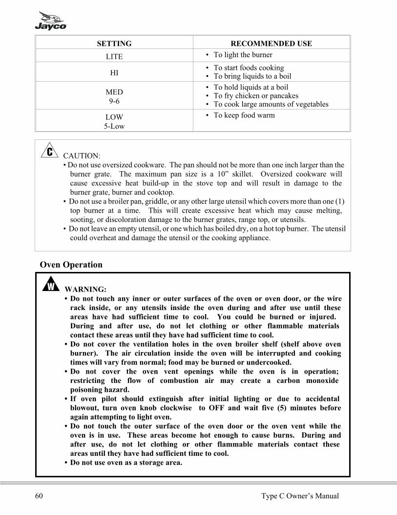
SETTING RECOMMENDED USE
LITE • To light the burner
HI• To start foods cooking• To bring liquids to a boil
MED9-6
• To hold liquids at a boil• To fry chicken or pancakes• To cook large amounts of vegetables
LOW5-Low
• To keep food warm
� CAUTION:• Do not use oversized cookware. The pan should not be more than one inch larger than theburner grate. The maximum pan size is a 10” skillet. Oversized cookware willcause excessive heat build-up in the stove top and will result in damage to theburner grate, burner and cooktop.
• Do not use a broiler pan, griddle, or any other large utensil which covers more than one (1)top burner at a time. This will create excessive heat which may cause melting,sooting, or discoloration damage to the burner grates, range top, or utensils.
• Do not leave an empty utensil, or one which has boiled dry, on a hot top burner. The utensilcould overheat and damage the utensil or the cooking appliance.
Oven Operation
� WARNING:
• Do not touch any inner or outer surfaces of the oven or oven door, or the wire
rack inside, or any utensils inside the oven during and after use until these
areas have had sufficient time to cool. You could be burned or injured.
During and after use, do not let clothing or other flammable materials
contact these areas until they have had sufficient time to cool.
• Do not cover the ventilation holes in the oven broiler shelf (shelf above oven
burner). The air circulation inside the oven will be interrupted and cooking
times will vary from normal; food may be burned or undercooked.
• Do not cover the oven vent openings while the oven is in operation;
restricting the flow of combustion air may create a carbon monoxide
poisoning hazard.
• If oven pilot should extinguish after initial lighting or due to accidental
blowout, turn oven knob clockwise to OFF and wait five (5) minutes before
again attempting to light oven.
• Do not touch the outer surface of the oven door or the oven vent while the
oven is in use. These areas become hot enough to cause burns. During and
after use, do not let clothing or other flammable materials contact these
areas until they have had sufficient time to cool.
• Do not use oven as a storage area.
60 Type C Owner’s Manual
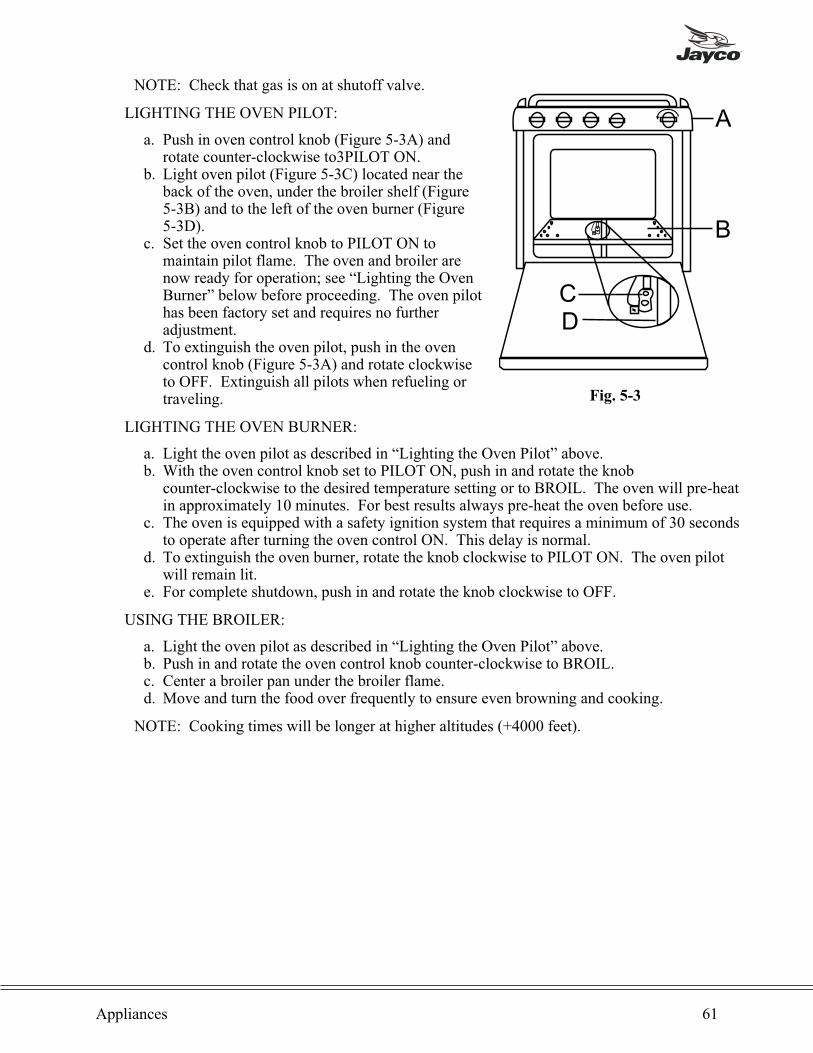
NOTE: Check that gas is on at shutoff valve.
LIGHTING THE OVEN PILOT:
a. Push in oven control knob (Figure 5-3A) androtate counter-clockwise to3PILOT ON.
b. Light oven pilot (Figure 5-3C) located near theback of the oven, under the broiler shelf (Figure5-3B) and to the left of the oven burner (Figure5-3D).
c. Set the oven control knob to PILOT ON tomaintain pilot flame. The oven and broiler arenow ready for operation; see “Lighting the OvenBurner” below before proceeding. The oven pilothas been factory set and requires no furtheradjustment.
d. To extinguish the oven pilot, push in the ovencontrol knob (Figure 5-3A) and rotate clockwiseto OFF. Extinguish all pilots when refueling ortraveling.
LIGHTING THE OVEN BURNER:
a. Light the oven pilot as described in “Lighting the Oven Pilot” above.b. With the oven control knob set to PILOT ON, push in and rotate the knob
counter-clockwise to the desired temperature setting or to BROIL. The oven will pre-heatin approximately 10 minutes. For best results always pre-heat the oven before use.
c. The oven is equipped with a safety ignition system that requires a minimum of 30 secondsto operate after turning the oven control ON. This delay is normal.
d. To extinguish the oven burner, rotate the knob clockwise to PILOT ON. The oven pilotwill remain lit.
e. For complete shutdown, push in and rotate the knob clockwise to OFF.
USING THE BROILER:
a. Light the oven pilot as described in “Lighting the Oven Pilot” above.b. Push in and rotate the oven control knob counter-clockwise to BROIL.c. Center a broiler pan under the broiler flame.d. Move and turn the food over frequently to ensure even browning and cooking.
NOTE: Cooking times will be longer at higher altitudes (+4000 feet).
Appliances 61
A
B
CD
Fig. 5-3

WATER HEATER
Several options are available in the water heater appliances. (1.) 6 or 10 gallon capacities,depending on floor plan. (2.) Three types of energy, LP gas only, LP gas and 120-voltcombination, and 12-volt/LP gas combination with 110-volt. Water temperature is adjustable onpilot and 120-volt models, but not on combination unit.
� WARNING: EXPLOSION OR FIRE
• DO NOT store or use gasoline or other flammable vapors and liquids in the
vicinity of this or any other appliance.
• Should overheating occur, or gas supply fail to shut off, turn OFF manual
gas control valve to appliance, or turn gas OFF at the LP tank. On
ELECTRONIC IGNITION MODEL turn operating switch to OFF
position and remove red wire from left hand terminal of ECO switch or
turn gas OFF at the LP tank
• Use with LP gas only.
• Shut off gas appliances and pilot lights when refueling.
• On PILOT RELIGHT MODELS, turn off the ignition module when
refueling gasoline tanks or LP tanks.
• Turn gas OFF at the LP tank when vehicle is in motion. This disables all
gas appliances and pilot lights. Gas appliances must never be operated
while vehicle is in motion. Unpredictable wind currents may be crated
which could cause flame reversal in the burner tube, which could result in
fire damage. The thermal cut off fuse could also be unnecessarily activated
resulting in a complete shutdown of the water heater requiring
replacement of the thermal cut off. See maintenance of electronic ignition
water heaters for further explanation of the thermal cut off.
• LP tanks must be filled by a qualified gas supplier only.
Operation
� CAUTION: Do not smoke or have any flame near an open faucet.
If water heater has note been used for more than two weeks, hydrogen gas may form in waterline. Under these conditions to reduce the risk of injury, open hot water faucet for severalminutes at kitchen sink before you use any electrical appliance connected to hot water system.
If hydrogen gas is present, you will probably hear sounds like air escaping through the pip aswater begins to flow.
� CAUTION:• Do not tamper with the pilot orifice.• Do not operate without water in tank.
62 Type C Owner’s Manual
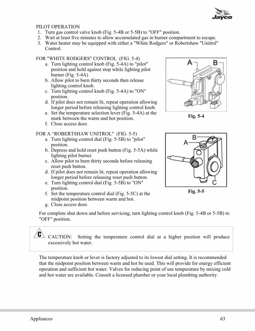
PILOT OPERATION1. Turn gas control valve knob (Fig. 5-4B or 5-5B) to "OFF" position.2. Wait at least five minutes to allow accumulated gas in burner compartment to escape.3. Water heater may be equipped with either a "White Rodgers" or Robertshaw "Unitrol"
Control.
FOR "WHITE RODGERS" CONTROL (FIG. 5-4)a. Turn lighting control knob (Fig. 5-4A) to "pilot"
position and hold against stop while lighting pilotburner (Fig. 5-4A)
b. Allow pilot to burn thirty seconds then releaselighting control knob.
c. Turn lighting control knob (Fig. 5-4A) to "ON"position.
d. If pilot does not remain lit, repeat operation allowinglonger period before releasing lighting control knob.
e. Set the temperature selection lever (Fig. 5-4A) at themark between the warm and hot position.
f. Close access door.
FOR A “ROBERTSHAW UNITROL" (FIG. 5-5)a. Turn lighting control dial (Fig. 5-5B) to "pilot"
position.b. Depress and hold reset push button (Fig. 5-5A) while
lighting pilot burner.c. Allow pilot to burn thirty seconds before releasing
reset push button.d. If pilot does not remain lit, repeat operation allowing
longer period before releasing reset push button.e. Turn lighting control dial (Fig. 5-5B) to "ON"
position.f. Set the temperature control dial (Fig. 5-5C) at the
midpoint position between warm and hot.g. Close access door.
For complete shut down and before servicing, turn lighting control knob (Fig. 5-4B or 5-5B) to"OFF" position.
� CAUTION: Setting the temperature control dial at a higher position will produceexcessively hot water.
The temperature knob or lever is factory adjusted to its lowest dial setting. It is recommendedthat the midpoint position between warm and hot be used. This will provide for energy efficientoperation and sufficient hot water. Valves for reducing point of use temperature by mixing coldand hot water are available. Consult a licensed plumber or your local plumbing authority.
Appliances 63
Fig. 5-4
AB
C
Fig. 5-5

TO ADJUST MAIN BURNER (FIG. 5-6):1. Loosen air shutter screw (Fig. 5-6A).2. Slide air shutter (Fig. 5-6B) to the right until some yellow
appears in the main burner flame.3. Move air shutter (Fig. 5-6B) to left until yellow disappears.4. Retighten air shutter screw (Fig. 5-6A).
Read MAINTENANCE AND CARE INSTRUCTIONS.
Electric Ignition Operation
1. Refer to Wiring Diagram in the manufacturer's manual. Place remote switch in the "ON"position.
2. If remote switch light stays on longer than fifteen seconds, place remote switch in the "OFF"position and wait five minutes.
3. Repeat step one of adjusting main burner.4. For complete shut-down and prior to servicing:
a. Place remote switch in the "OFF" position.b. Remove red wire from left hand terminal of ECO switch
(ECO to valve).5. If heater fails to operate due to high water temperature, a
lockout condition occurs (indicator light on). After water cools,reset switch in the "OFF" position for at least thirty seconds,then return to "ON" position.
6. If a lockout condition persists contact an Atwood Service Center.
Read MAINTENANCE AND CARE INSTRUCTIONS & ELECTRONIC IGNITIONMAINTENANCE.
Pilot Re-ignite Operation
1. Turn the switch located on the spark module to the "ON" position.2. Read Pilot Operation Instructions.3. For complete shut down, turn lighting control knob on thermostat and spark module switch to
the "OFF" position.
Read MAINTENANCE AND CARE INSTRUCTIONS.
64 Type C Owner’s Manual
Fig. 5-6
Fig. 5-7

Combo gas/electric Electric Operation
1. For gas operation refer to Pilot, Pilot Relight or Electronic Ignition OPERATION.2. For electrical operation, use the switch inside the mini-motorhome in the utility panel.3. Completely fill tank with water.4. Turn switch (Fig. 5-8) located in the mini-motorhome to the "ON" position.
NOTE: Turning the power on in the heater with little or no water covering the heatingelement may burn out the element and void the warranty.
5. Check for proper operation. Water temperature should be approximately 140°F (60°C).6. If the manual reset high temperature limit switch should operate, reset the switch (Fig. 5-9)
by depressing the button. Use a pencil or other nonmetallic object. If still experiencingproblems contact an authorized Atwood Service Center or Atwood Service Department.
Read MAINTENANCE AND CARE INSTRUCTIONS.
When cold water is heated in the tank, the pressure will rise. For this reason, a relief valve (Fig.5-10) is required for safety in all water heaters, rated at 125° (52° C). It is normal for this valveto release a small quantity of water during the heating cycle. Opening a faucet on the hot sidewill release pressure reducing relief valve dripping.
Water Heater Maintenance
Refer to information in Chapter 6.
Appliances 65
Fig. 5-8
Fig. 5-9
Fig. 5-10
REFRIGERATOR
� WARNING:• The storage of flammable materials behind or around the refrigerator
creates a fire hazard. Do not use the area behind the refrigerator to storeflammable materials (gasoline, cleaning supplies, etc.)
• Do not remove the round ground prong from any of the AC power cords.Do not use a two prong adapter or an extension cord with any of the ACpower cords. Ground the 120-volt AC circuit in compliance with anyapplicable local, state, or national codes. Do not use an extension cord.
• A circuit overload can result in an electrical fire if the wires and/or fusesare not the correct size. Use only the wire and fuse sizes as a written in the“Installation Manual”.
• Incorrect installation, adjustment, change to, or maintenance of thisrefrigerator can cause personal injury, property damage, or both. Haveservice and maintenance work done by your dealer or by a Norcoldauthorized service center.
• Disconnect both the AC and DC power sources before doing anymaintenance work on the refrigerator. All service work on thisrefrigerator must be done by a qualified service technician.
• Do not bypass or change the refrigerator’s electrical components orfeatures.
• When you discard an appliance, remove all doors to prevent accidentalentrapment and suffocation.
• Do not spray liquids near electrical outlets, connections, or the refrigeratorcomponents. Many liquids are electrically conductive and can cause ashock hazard, electrical shorts, and in some cases fire.
• The refrigerator cooling system is under pressure. Do not try to repair orto recharge a defective cooling system. The cooling system contains sodiumchromate. The breathing of certain chromium compounds can causecancer. The cooling system contents can cause severe skin and eye burns,and can ignite and burn with an intense flame. Do not bend, drop, weld,move, drill, puncture, or hit the cooling system.
� CAUTION:• The rear of the refrigerator has sharp edges and corners. To prevent cuts orabrasions when working on the refrigerator, be careful and wear cut resistantgloves.
• Make sure all fasteners and connections are tight.
66 Type C Owner’s Manual

About Your Refrigerator:
LEVELING
� CAUTION: The refrigerator is made to operate within 3” off level side-to-side and 6” offlevel front-to-back (as looking at the front of the refrigerator). Operating it at more thanthese limits can cause damage to the cooling system and create a risk of personal injury orproperty damage. Make sure the vehicle is level before you operate the refrigerator.
OPERATION DURING TRAVEL
While the refrigerator should be level when the vehicle is stopped, performance during travel isnot usually effected.
FOOD COMPARTMENT
Ignite or start up the refrigerator and let it cool for eight hours before loading with food. If therefrigerator does not start to cool down after about two hours, contact your dealer or a Norcoldauthorized service center.
• For the best cooling performance:• Let air move freely inside the entire food compartment.• Do not cover the shelves with plastic, paper, etc.
• To decrease the amount of ice that collects on the cooling fins:• Cover all liquids and moist foods.• Let all hot foods cool before putting them in the refrigerator.• Do not open the door any longer than necessary.
FREEZER COMPARTMENT
The freezer compartment is made to keep pre-frozen food frozen and not to quick freeze food.Keep pre-frozen foods in the freezer compartment.
NOTE: Do not put other items on the ice tray while the water is freezing. The waterfreezes more rapidly if the thermostat is at the COLDEST position.
CRISPER
The crisper is located at the bottom of the fresh food compartment and supply a storage area topreserve fruit and vegetable freshness. Make sure that you always push the crispers fully in.
NOTE: Do not wash the crispers in a dishwasher. The crispers are not dishwasher safe.
DOOR BINS
You may put the door bins of the freezer and fresh food compartment in a location that bestmeets your needs. To remove the bins, lift them over the locator and pull them forward. TOinstall the bins, push them onto the locator.
NOTE: Do not wash the door bins and bin slides in a dishwasher. The door bins and binslides are not dishwasher safe.
Appliances 67

ADJUSTABLE SHELVES
The shelves in the freezer and the fresh food compartment are made so you can remove them ormove them.
• To remove or move the shelf of the freezer:• Pull the shelf forward out of the slot.• Push it fully into the slot that you wish.
• To remove or move each shelf of the fresh compartment:• Remove the screw from the retainer of each shelf at the rear of the refrigerator.• Pull each shelf forward out of the slot.• Push each shelf fully into the slot that you wish.• Attach the retainer with the screw.
DOOR HANDLES
During travel, the door latch prevents the door from operating. When closing each door, pushthe door toward the refrigerator until you hear a “click” sound.
To open each door, pull the handle away from the refrigerator.
During storage, the storage latch prevents the door from completely closing. Use it to preventodors when the refrigerator is stored for an extended period of time.
To operate the storage latch, open each door about 1/2” and push the storage latch into thecutout of the strike plate. Do not use the storage latch as a travel latch because the doors willnot be fully closed.
DOOR BIN SLIDE (MODEL N982)
Each bin includes an adjustable bin slide to prevent bin contents from moving or overturningwhile in transit. Push the slide against the bin contents until they are secure. To remove thedoor bin slid, rotate it out of the door bin by pulling up from the bottom. To reinstall, reversethis procedure.
DOOR ALARM (MODEL N982)
If the lower door remains open and the interior light remains on for more than two minutes thelight turns off, a warning beepers sounds, a bell flashes and code A3 appears in the centerdisplay panel. Refrigerator operation will not be interrupted; this alarm is intended to alert youto the fact that the door is ajar. Closing the door will turn off the alarm.
INTERIOR LIGHTS
The interior light is at the top of the fresh food compartment. It comes on only when therefrigerator is on the door is open. To replace the bulb:
1. Remove the DC power supply wires from the power board at the rear of the refrigerator.2. Remove by pulling the cover toward the front of the refrigerator.3. Remove the light bulb from the holder.
NOTE: Use only a GE#214-2 bulb as the replacement bulb. This bulb is available atmost retail automotive parts centers.
4. Install the replacement bulb.5. Install the cover.6. Connect the DC power supply wires to the power board at the rear of the refrigerator.
68 Type C Owner’s Manual
MOISTURE REDUCTION HEATER
The refrigerator has a heater that prevents moisture from forming on the center divider betweenthe doors of the freezer and the fresh food compartment. The heater operates only when therefrigerator is ON and the DC power is sufficient.
BACKUP OPERATING SYSTEM
This refrigerator has a backup operating system. The backup operating system allows therefrigerator to continue to cool if the temperature sensor of the refrigerator should fail.
If this failure occurs:
• The refrigerator automatically changes to the backup operating system.• The ON light flashes a fault code. See the “Fault Codes” Section of this manual.
• The backup operating system can over freeze or thaw the contents of the freezer and the freshfood compartment.• Make sure the temperatures of the freezer and the fresh food compartment aresatisfactory.
NOTE: If you open the door(s) too often, the temperatures inside the freezer and freshfood compartment do not become stable. Allow the refrigerator to operate forabout one hour after each adjustment change before you examine the contents.The number “5” is the coldest temperature setting.
• If the temperature is too warm, push the temperature switch to the right to raise thetemperature setting by one number.
• If the temperature is too cold, push the temperature switch to the left to lower thetemperature setting by one number.
• Have the refrigerator serviced by your dealer or a authorized Service Center as soon aspossible.
Appliances 69

Model N821
CONTROL PANEL
The refrigerator control panel is between the freezer compartment and the fresh foodcompartment. To maintain the operating control functions of the refrigerator, a 12-volt DCpower supply is necessary. The refrigerator and any other DC components in the vehicle,receive DC power from the 12-volt system of the vehicle; either an auxiliary battery, aconverter, or the vehicle engine battery.
The ON/OFF button (A) starts and shuts down the refrigerator:
• If the refrigerator is shut down, press the ON/OFF button to start the refrigerator in auto mode.• If the refrigerator is operating, press and hold the ON/OFF button for two seconds to shutdown the refrigerator.
The TEMP SET button (B) controls the temperature adjustment of the freezer ant the fresh foodcompartment. The temperature adjustment that you select does not change if the mode ofoperation of the refrigerator changes:
• Push the TEMP SET button and the temperature setting “1-9” appears in the center display(C).• Push and hold the TEMP SET button and the temperature setting changes.
• The number “9” is the coldest temperature setting.
The MODE button (D) controls the operation mode of the refrigerator:
• Push and hold the MODE button and a light bar flashes in the center display beside each of thefour operating modes of the refrigerator, one at a time.• There is one automatic mode of operation and three manual modes of operation.• When the light bar flashes beside the mode of operation that you wish, release the MODEbutton.
AUTOMATIC MODE OPERATION
When you select AUTO mode, the refrigerator controls automatically select the most efficientenergy source that is available for operation. If a more efficient energy source becomesavailable, the refrigerator controls change from the current energy source to the more efficientenergy source.
70 Type C Owner’s Manual
NORCOLD ACAUTO
LP GASDC
1-COLD COLDEST-9
ON
OFFMODETEMP
SET
ABC D
Fig. 5-11

The controls select the energy source in this sequence:
• When 120-volt AC is available to the refrigerator:• The light bars beside AUTO and AC show in the center display.• After ten seconds, the light bar beside AC goes off and only the light bar beside autoremains.
• This means that the refrigerator is operating on AC electric.• If 120-volt AC is not available to the refrigerator:
• The light bars beside AUTO and LP GAS show in the center display.• After ten seconds, the light bar beside LP goes off and only the light bar beside AUTOremains.
• This means that the refrigerator is operating on propane gas.
If an energy source is available to the refrigerator, but is not operating correctly:
• A fault code appears in the center display.• The refrigerator controls try to change to a less efficient energy source.• If a less efficient energy source is not available:
• The refrigerator stops operation.• Refer to the “Fault Codes” in the manufacturer’s owner’s manual.
MANUAL MODE OPERATION
When you select one of the manual modes of operation, the light bar beside the AUTO goes outin the center display and only the light bar beside either AC, LP, or DC remains.
• AC means that the refrigerator is operating on AC electric.• LP means that the refrigerator is operating on propane gas.
If the energy source is interrupted:
• The refrigerator stops operation.• Refer to the “Fault Codes” in the manufacturer’s owner’s manual.
OPERATION OF PROPANE GAS IN EITHER AUTO OR MANUAL MODE
NOTE: On initial start up of the refrigerator, ignition of the propane gas may not occurwithin 30 seconds.
If ignition of the propane gas does not occur within 30 seconds:
• The gas safety valve of the refrigerator closes.• The refrigerator stops operation.• Refer to the “Fault Codes” in the manufacturer’s owner’s manual.• The fault code remains until you push the ON/OFF button two times (to stop and start therefrigerator).
• If ignition does not occur after two or three times:• Check the gas supply line.• Consult your local dealer or an authorized Norcold Service Center.• Change to manual mode and operate on AC electric.
Appliances 71

900 Series Information
REFRIGERATOR CONTROLS AND OPERATING INSTRUCTIONS
A 12-volt DC supply is required to maintain the refrigerator’s operating control functions. Therefrigerator receives its DC power from the vehicle’s 12-volt system; either an auxiliary battery,a converter or the engine battery. The 12-volt DC system not only supplies power to therefrigerator, but to other DC components in the vehicle.
The control panel, positioned between the freezer compartment and the fresh food compartment,conveniently locates all the functionality needed by the owner. The window (A) of the controlpanel is equipped with a light which illuminates the LCD display. This light turns on when anybutton is pressed, and remains on for 10 seconds after the button is released.
The On/Off button (E) turns the refrigerator “On” or “Off”. When the refrigerator is “Off”,pressing this button will turn the refrigerator “On” and set the mode to “AUTO”. When therefrigerator is “On”, pressing this button for 2 seconds will turn the refrigerator “Off”.
Pressing and holding the “MODE” button (C) allows that user to cycle through the four modechoices; one “AUTO” and three manual modes (AC, LP GAS, OR BATT). The refrigeratorwill not switch to the new operating mode until the “MODE” button is released.
The “TEMP SET” (thermostat) button (D) controls the refrigerator and freezer temperatureduring both gas and electric operation, eliminating the need to reset each time a different energysource is selected. Press and hold the “TEMP SET” button to select the desired temperaturesetting. The temperature settings are shown in the form of a thermometer (B) in the displaywindow, with the shortest thermometer reading indicating the coldest setting.
AUTO MODE
When the “AUTO” mode is selected, the operating control automatically selects the energysource using the following priority scheme:
• When 120-volts AC is available to the refrigerator, “AUTO AC” will be visible in the displaypanel, indicating the refrigerator is operating on AC electric.
• If 120-volts AC is not available, the refrigerator will switch to the gas operation, and “AUTOLP GAS” will be visible in the display panel.
• When neither 120-volts AC nor LP gas are available, the refrigerator will switch to DCelectric (3-Way models only) and “AUTO BATT” will be visible in the display panel. DCelectric operation is not as efficient as LP gas or AC electric operation, and should thereforebe used only to maintain temperatures when the other modes are unavailable (for example;while in transit).
72 Type C Owner’s Manual
NORCOLD ON
OFF
TEMPSET
MODEAUTO LP GAS
AC BATT
A
B
C D E
Fig. 5-12
During operation in the “AUTO” mode, when a higher priority energy source becomesavailable, the operating controls will cease using the current energy source and will switch tothe higher priority energy source. For example, if AC electric becomes available while therefrigerator is operating in the “AUTO LP GAS” mode, the refrigerator will switch to “AUTOAC” operation.
If an operating mode is not functional, a diagnostic code will appear and the refrigerator willattempt to operate in a lower energy priority source. If a lower energy priority is not available,an alarm will sound and the refrigerator will cease operation. Refer to the “Diagnostic Codesand Their Meaning” for corrective actions.
MANUAL MODE
To operate in the “MANUAL” mode, press and hold the “MODE” button until “AUTO”disappears and the desired operating mode is displayed. If the energy source is interrupted whileoperating in the “MANUAL” mode, a diagnostic code will appear, an alarm will sound and therefrigerator will cease operation. Refer to the “Diagnostic Codes and Their meaning” sectionfor corrective actions.
“AUTO” AND “MANUAL” MODES - GAS OPERATION ONLY
If the gas does not ignite withing 30 seconds, which may occur on initial start-up, therefrigerator’s gas valve will automatically close and the operating controls will select analternate energy source (”AUTO” Mode) or, “MANUAL” mode, will revert to a stand-by modein which an alarm will sound and code A1 will be displayed in the center window. The alarmand code will remain on until the operating controls are turned “OFF” and then “ON” again. Ifthe gas does not ignite after several attempts, check the input gas supply, or consult with yourdealer or a Norcold authorized service center. A different mode of operation may be selected bypressing and holding the “MODE” button. The refrigerator will not switch to the new operatingmode until the “MODE” button is released.
BACKUP OPERATING SYSTEM (BOS)
The refrigerator’s operating controls feature a Back-Up Operating System which provides ameans for the refrigerator to cool in the event of a failure with the temperature sensor. Once the“BOS” mode is entered, the temperature sensor is ignored and the control will displayDiagnostic Code C5 and will switch automatically to the “BOS” mode. This mode providesrefrigeration until the refrigerator is serviced. Although the refrigerator can operate in thismode, Norcold recommends that the refrigerator owner seek service as soon as practical torestore normal operation.
DIAGNOSTIC CODES
The refrigerator's operating controls are equipped with a diagnostic system which alerts the userto a problem in any mode of operation. When a problem occurs within a given mode, theoperating controls will revert to a standby mode in which an alarm will sound and a diagnosticcode will be displayed in the center control window. The alarm will sound until an alternateoperating mode is selected.
The diagnostic code will continue to be displayed until the controls are turned OFF and thenback ON. For code interpretation, see manuals written and published by the manufacturer ofyour refrigerator.
Appliances 73

MONITOR PANEL
This electronic control panel and information center is located inside the mini-motorhome doorat the end of the upper cabinet behind a smoke glass door. Information data and controls are ateye level for easy operation. Energy to operate the panel is 12-volt DC, supplied by the auxiliarybattery and/or power center. The fuse is located in the power center also.
All operating functions are explained below:
1. Pump - press 2 position rocker switch to start/stop water pump.2. Heater - press 2 position rocker switch to turn water heater 12-volt power on or off.3. Test - Information center - press spring loaded switch to receive the following messages.
a. Volume of liquid in each listed tank.b. Condition of battery, charge, good, fair, and low at 6 volts.
AIR CONDITIONER
Operation
FOR COOLING1. Turn the selector switch to the “LOW COOL” or “HIGH COOL” position.2. Rotate the thermostat (temperature control) to the position that is the most comfortable to
you. The thermostat will turn the compressor on when the temperature of the air entering theair conditioner rises a few degrees above the setting you have selected. Then the temperatureof the air entering continues to cycle the compressor on and off in the above mentionedfashion until the selector switch is turned to another mode of operation.
3. Position the louvers to the desired direction the discharge air is to flow.
NOTE: The fan operation is constant, only the compressor cycles on the thermostat.
OPERATION DURING COOLER NIGHTS
It is important, when the outdoor temperature drops in the evening or during the night to below75°F that the thermostat (temperature control) be set at a midpoint between “warmer” and“cooler”. If the setting is at “cooler”, the evaporator coil may become iced-up and stop cooling.During the day when the temperatures have risen above 75°F, reset the thermostat switch to thedesired setting.
74 Type C Owner’s Manual
F
2/3
1/3
E
FRESH HOLDING GRAY 1 GRAY 2 BATTERY
C
G
F
L
TE
ST
PU
MP
HE
AT
ER
Fig. 5-13

NOTE: Should icing-up occur, it is necessary to let the cooling (evaporator) coil defrostbefore normal cooling operation is resumed. During this time, operate the unit inthe “HIGH FAN” position with the system at maximum air flow. Whenincreased or full air flow is observed, the cooling coil should be clear of ice.
SHORT CYCLING
When an air conditioner is in operation , its compressor circulates refrigerant under highpressure. Once off, it will take two to three minutes for this high pressure to equalize.
The air conditioning compressor is unable to start against high pressure. Therefore, once the airconditioner is turned off, it is important to leave it off for two or three minutes before restarting.
Short cycling the compressor (or starting it before pressures have equalized), will in someinstances, kick the circuit breaker or overload.
FOR AIR CIRCULATION ONLY1. Turn the selector switch for “LOW FAN” or for maximum air flow, to “HIGH FAN”.2. Position the louvers to the desired direction the discharge air is to flow.
NOTE: When the selector switch is in the “LOW FAN” or “HIGH FAN” position, the blowermotor will operate continuously.
Appliances 75

Chapter 6
CARE AND MAINTENANCE
EXTERIOR
� CAUTION: We do not recommend you take your recreation vehicle through automatic carwashes and extreme caution should be used if utilizing any type of pressure sprayer aroundall attachments, doors, windows, appliance vents, etc. to avoid forcing water inside thevehicle, possibly damaging components.
Roof
The roof of your mini-motorhome is covered with TPO roofing material. The proper care,cleaning and maintenance of your TPO Roofing is quite simple because of the basic propertiesand longevity of the material itself.
Periodic cleaning is the primary maintenance. Alpha Systems suggest using Murphy® Oil Soapwith a soft nylon brush or sponge. DO NOT USE solid or granulated cleaners, as they will marthe natural finish.
DO NOT USE Armor All® or other oil/solvent base cleaners as they will leave a slick surface.
A good thorough cleaning with some elbow grease and the suggestions above should keep yourroof looking good and remove most stains. For more stubborn stains, you should contact yourauthorized dealer.
If you keep your Royal Tuff-Ply™ TPO roof clean, you will be performing the primarymaintenance necessary to keep it looking good and extend its longevity.
Annual inspection of the roof is suggested. Check the membrane for possible damage andcheck the caulk/lap sealant used in all termination areas and around all accessories andfasteners.
Royal Tuff-Ply™ is UV resistant. It will not retain odors or rot.
� CAUTION: All roofs require maintenance. At least twice a year, inspect and reseal allseams: front and rear, around all vents, and along all moldings. If you notice anydeterioration in the seal, scrape off any cracked, lifting or loose sealant and reseal the area.Contact your dealer for the appropriate sealant to use.
Fiberglass Sidewalls
Fiberglass walls are very durable and are easy to maintain. To keep them looking nice, wax andbuff them once a year. Standard automotive cleaning soaps and waxes work well for generalcleaning and maintenance. Special cleaners and waxes are available at automotive and RVstores.
Scratches and chips can be easily fixed by an experienced fiberglass repair shop. Any majordamage should be repaired as soon as possible to prevent cracks from becoming larger.
76 Type C Owner’s Manual
Doors, Extrusions, Windows & Vents
These components have putty tape between the component and the wall surface. Portions ofthese items may have a cap seal added as a secondary seal. Inspect these seals at least once ayear. Both putty tape and cap seals can become damaged by U.V. exposure, air pollution,freezing temperatures and other exposure to the elements. If deteriorated, repair immediately toprevent damage. Cap seal all trim and openings at least once after the first year, and thereafter ascracks, peeling, lifting and shrinking occur.
The entrance door installed in your recreation vehicle is the result of years of design and testing;to provide you with the most carefree and functional product available. To keep your dooroperating in the manner in which it was designed and delivered to you, there are some routinemaintenance items that should be handled on a regular basis.
• Strike plate or bolt adjustment - The door in your motorhome was installed and adjusted in afactory setting and the setting of the striker plate or bolt may change over the course of timeand road conditions and that setting may need to be changed or adjusted to insure that yourdoor operates as smoothly and efficiently as it should. To adjust the strike plate, you will needto loosen the two screws holding the strike plate to the jamb system. Move the plate in or outas needed to obtain a proper seal and closing force and re-tighten the screws. To adjust thestrike bolt in the rotary lock, loosen the bolt with a 5/8” socket or box end wrench, move thebolt in the direction needed to re-tighten the bolt to 35 foot pounds of torque. The door inyour motorhome operates much like an automobile door and must be closed firmly to enablethe lock to engage the secondary locking or fully closed position.
• Locks - The key cylinder in your locks need to be lubricated on an annual basis or as needed.Always use powdered graphite never a petroleum product. The petroleum product will gumup the cylinder and cause it to not operate smoothly. Apply a light coating of white lithiumgrease tot he face of the lock bolt to obtain a smooth closing.
• Hinges - The hinges on your door should be lubricated annually or as needed with any highquality spray lubricant.
• Fiberglass skin - To maintain good appearance and long service life, the door skin panelsshould be washed and cleaned periodically. Cleaning removes the accumulation of dust anddirt, which can combine with sunlight, and wind to attack exposed surfaces both chemicallyand abrasively. The following methods and materials are suggested for cleaning fiberglassdoor skin panels:
� CAUTION: Before using the following cleaning materials and methods, conduct a test withthe product and procedure on the corner of the door.
• General Cleaning - A 10% solution of trisodium phosphate in warm water (not to exceed120°F), may be applied in a scrubbing motion, using sponge, brush or cloth. Rinsethoroughly after cleaning.
• Removing Oil Residues or Difficult Substances - Mineral spirits, applied with a cleancloth, will aid in removing moist oily residues or substances.
• Removing Hard Water Deposits - A 10% solution of acetic acid in cold water may beused in the manner described in General Cleaning above. Rinse thoroughly aftercleaning.
Waxing, though not mandatory, will help maintain the appearance and service life of the door.If waxing, use a high quality automotive or recreation vehicle wax; non-abrasive.
NOTE: Use non-corrosive cleaning compounds. Avoid the use of compounds containingammonia or chlorine since they may cause the panels to yellow. DO NOT userubbing compounds, as they will etch and damage the panel surface.
Care and Maintenance 77

Chassis
Instructions for drive train and automotive chassis are included in the manual supplied by thechassis manufacturer.
A frame extension has been added to your mini-motorhome chassis. You may wish to have anundercoating material applied to the frame extension to protect your investment from the effectsof road grime, salts, and other corrosive materials. Contact your chassis manufacturer beforeapplying undercoating to the chassis frame. Frames will rust much sooner in salt exposed areasthan in dry air. Also, frames will receive heavy abuse from roads, such as sand, pebbles, objectson the highway, all of which will cause chipping and a blasting effect on the painted surface.For these reasons it will be necessary to inspect, clean and repaint the steel members to preventexcessive rust and insure a longer life of the frame.
Front Axle Alignment
The term alignment refers to both the adjustment angles on the steering axle and suspension andtracking of the rear axle. Many factors are considered when establishing proper alignment.Steering components, suspension, wheel bearings and even proper loading will affect yourmini-motorhome alignment. To ensure accuracy, your mini-motorhome alignment was verifiedat our manufacturing facility before shipment to your dealer.
We recommend you have the front suspension and steering alignment checked and adjustedafter you have fully loaded the vehicle according to your needs as part of the vehiclemaintenance. Thereafter, it is your responsibility to have the alignment inspected periodically tomaintain vehicle steering performance and prevent uneven tire wear as part of your normalmaintenance. Always have the alignment checked and adjusted by a qualified shop with
the proper equipment to handle heavy vehicles.
NOTE: A road test by the dealer should be included as part of the pre-delivery inspection.The dealer can then check for and correct any steering problems before you takedelivery of the motorhome. After this road test has been completed, front-endalignment and/or vibrations will not be covered as part of the new vehicle limitedwarranty.
78 Jay Flight Owner’s Manual
Tire Changing
Your recreation vehicle may be equipped with Versa-Liner Wheel Liners. The followinginstructions will give you direction for removing and reinstalling the wheel liners whennecessary.
VERSA-LINER® WHEEL LINERS
NOTE: DO NOT loosen or remove lug nuts. Set the vehicle parking brake prior to wheelproduct installation.
NOTE: These wheel liners can be installed with the installation tool supplied with thewheel liner kit. Keep this tool stored with your vehicle tire tool. No other toolsare necessary to remove or install the wheel liners. Do not use power tools forinstallation or removal
INSTALLATION:1. FRONT - Align the valve stem cut out in the front Versa-Liner with the valve stem on the
wheel.2. Secure with two enclosed steel jam nuts. Securely tighten each jam nut with the installation
tool provided.3. REAR - Align the openings in the rear Versa-Liner with the openings in the wheel.4. Mount the rear Versa-Liner using two lug nut covers with the enclosed steel jam nut and the
installation tool provided.
NOTE: Check for tightness after the first 50 to 100 miles of operation. Recheckperiodically.
Reverse the installation process to remove the wheel liners.
CARE AND MAINTENANCE:• Clean only with a mild soap and water.• Do not use harsh detergents, acids or abrasives.
Periodically check the enclosed jam nut for tightness.
Care and Maintenance 79

INSPECTION POINTS FOR SEALING
The following diagram indicates the locations that need to be inspected semi-annually andresealed at least one time each year.
80 Type C Owner’s Manual
1. Moldings2. TV Antenna3. Vents
4. Windows5. Exterior Attachments6. Marker & Tail Lights
INTERIOR CARE
Refrigerator
REFRIGERATOR CARE CHECKLIST
Your refrigerator will give you years of trouble free service if you do these simple checks everythree to six months:
• Keep the food compartment and the freezer clean. See “Defrosting” and “Cleaning”.• Defrost the refrigerator as necessary. See “Defrosting” and “Cleaning”.• Make sure the door seals correctly. See “Door Sealing”.• Be aware of any cooling changes that are not because of weather, loading, or gas controlchanges. If changes occur, contact your dealer or service center.
• Make sure the gas supply is propane gas only and not butane or a butane mixture.• When in propane gas operation, examine the appearance of the flame. See “Gas FlameAppearance”.
• Make sure the air flow in the lower intake vent, through the refrigerator coils and condenser,and out the upper exhaust vent is not blocked or decreased.
• Make sure the area behind the refrigerator is clear. Do not use the area behind the refrigeratorfor storage of any combustible materials, especially gasoline and other flammable vapors andliquids.
DEFROSTING
The cooling fins of the refrigerator operate at below freezing temperature and will naturallyform frost from humidity, which is always present in the air. The humidity inside therefrigerator increases:
• With higher outside temperature and humidity.• With the storage of non-sealed fresh foods or warm foods.• With the amount of time that the door(s) are open.• With any air leakage into the refrigerator.
Although the refrigerator is not frost free, it is made to limit frost on the cooling fins. At regularintervals, the temperature control system automatically melts most of the frost from the coolingfins. The water from the cooling fins drains into a collection cup that is attached to the back ofthe refrigerator. The heat of the cooling system evaporates the water from the collection cup.
It is normal for frost to collect inside the freezer. Excess frost decreases the coolingperformance of the refrigerator. Defrost the refrigerator as necessary:
• Remove all food from the refrigerator.• Push the selector switch to the OFF position to shut down the refrigerator.
NOTE: Defrosting the refrigerator makes excess water inside the refrigerator.
• Put dry towels (etc.) inside the refrigerator to absorb the water.• Put trays of hot water in the freezer until the frost is melted.• Empty the drip tray.• Remove the wet towels (etc.) and dry the interior.• Put the drip tray and all food in the refrigerator.• Ignite or start up the refrigerator.
Care and Maintenance 81
CLEANING
A good time to clean the refrigerator is just after you defrost it. Clean the inside of therefrigerator as often as necessary to avoid food odors:
• Remove all food from the refrigerator.
NOTE: Do not use abrasive cleaners, chemicals, or scouring pads because they candamage the interior of the refrigerator. “Dawn”, “Fantastic”, and “Formula 409”are the brand names of three products that are recommended to use.
• Wash the interior with a mild cleaner or a solution of liquid dish detergent and warm water.• Rinse with a solution of baking soda and clean water.• Dry with clean cloth.• Put all food in the refrigerator.
DOOR SEALING
If either door does not seal correctly, excess frost will collect inside the refrigerator. Make surethe doors seal correctly:
• Close each door on a piece of paper that is about the size and thickness of a dollar bill.• Gently pull the paper.
• You should feel a slight drag between the gasket and the cabinet.• Do this on all four sides of the door.• If you do not feel a slight drag on the paper, the door does not seal correctly.• Have your dealer or an authorized Service Center correct the seal of the door.
REFRIGERATOR MAINTENANCE CHECKLIST
Read and understand the following maintenance sections.
NOTE: Norcold is not responsible for installation, adjustment, alteration, service, ormaintenance performed by anyone other than a qualified RV dealer or a Norcoldauthorized service center.
Have a qualified RV dealer or a authorized service center do these annual safety andmaintenance checks:
• Examine the gas supply lines for leaks. Replace or repair if needed.• Make sure the propane gas pressure is correct. Adjust if needed.• Make sure the combustion seal is complete and intact. Replace or repair it if needed.• Make sure the burner and the burner orifice are clean. Clean if needed.• Make sure the electrode spark gap is correct. Adjust if needed.• Make sure the AC and DC voltages are correct. Adjust if needed.• Make sure the thermocouple tip is clean and secure.• Make sure the are at the rear of the refrigerator is free of any combustible materials, gasoline,and other flammable vapors and liquids.
82 Type C Owner’s Manual
REFRIGERATOR STORAGE
Before the refrigerator is stored for an extended (seasonal) period of time:
• Remove the black AC power cord from the receptacle and disconnect the DC power wires ofthe refrigerator.
• Defrost and clean the interior of the refrigerator.• Close the doors with the storage latch.
If the refrigerator is stored for an extended period of time, before ignition or start up:
• Make sure there are no obstructions in the burner, the orifice, or the flue.
REFRIGERATOR MAINTENANCE
GAS FLAME APPEARANCE:
While in GAS operation, examine the appearance of the gas flame:
• Turn the temperature switch to the COLDEST position.• Open the lower intake vent.
� CAUTION: The burner box cover can be hot. Wear gloves to avoid burns.
• Open the burner box door and look at the gas flame.• The flame should be a darker blue inside and a lighter blue outside and should be aconstant and steady shape.
• If the flame is yellow or has an erratic and unstable shape, contact your dealer orauthorized service center.
• Make sure the flame does not touch the inside of the flue tube.• If the flame touches the inside of the flue tube, contact your dealer or authorized servicecenter.
• Close the burner box door.
REFRIGERATOR FUSE REPLACEMENT
The electrical circuits of this refrigerator have fuses to protect them from an overload. If a fuseis unserviceable, replace it as follows.
� WARNING: Do not operate the refrigerator without the power board cover on the
refrigerator. To prevent a circuit overload and a possible electrical fire, use only these
fuses:
DC control circuit 5 amp tan blade type automotive fuse
AC circuit 5 amp glass cartridge fuse
1. Push the selector switch to the OFF position to shut down the refrigerator.2. Remove the black AC power cord from the receptacle.3. Remove the AC power cord from the power board that is at the rear of the refrigerator.4. Remove the DC power supply wires from the power board.5. Remove the ignition sense wire from the power board.6. Remove the gas valve wires from the power board.
Care and Maintenance 83
7. Remove the mounting screws and the power board cover.8. Replace the unservicable fuse(s) with the new fuse(s) of the correct type and size.9. Reverse this procedure and assemble the power board cover and all wiring.
If the fuse(s) continues to become unservicable, consult your dealer or a Norcold authorizedservice center.
Range and Oven
� WARNING:
• Make sure all controls are OFF and the range or cooktop is cool before
cleaning.
• Make sure that all cooktop surfaces, burner grates and bruners are cool
before cleaning or disassembling cooktop.
• Do not use oven cleaners, bleach, or rust removers on the cooktop or burner
grates.
• Do not obstruct the flow of combustion and ventilation air.
• Keep appliance area clear of combustible materials, gasoline and other
flammable vapors and liquids.
• Clean oven with oven cleaner only. Follow directions on the container.
• Never use a wire brush or metallic item for cleaning burner ports or orifices.
Brush may “shed” bristles, that may lodge in the orifice or burner ports and
cause a fire or explosion.
� CAUTION:• Clean all surfaces as soon as possible after boil overs or spillovers.• Use warm soapy water only to clean the burner grates, cooktops, painted surfaces,porcelain surfaces, stainless steel surfaces and plastic items on your range orcooktop. DO not use grit or acid-type cleaners.
• Do not use steel wool, or abrasive cleaners, or acid type cleaners such as chlorinebleach on your cooktop or grate systems. They will damage your range orcooktop. Use only non-abrasive plastic scrubbing pads.
• Do not allow foods containing acids (such as lemon or tomato juice, or vinegar) toremain on porcelain or painted surfaces. Acids may remove the glossy finish.Wipe up egg spills when cooktop is cool.
• Do not wash warm porcelain surfaces. Allow these areas to cool before cleaning.You could burn yourself, or the porcelain could crack.
• Pitting and discoloration will result if spills are allowed to remain for any length oftime on stainless steel.
• Do not allow spillovers to remain on the burner caps. The caps could becomepermanently stained.
• When cleaning around the burners, use care to prevent damage to the electrode (ifso equipped). If a sponge or clothe should catch the metal igniter electrode, itcould damage or break the electrode. If this occurs, the burner will not light.
84 Type C Owner’s Manual

The owner’s cooking habits and cleanliness will affect the operation of the range or cooktop.Proper installation and care will help keep your range or cooktop looking and operating likenew. Most cleaning can be performed using normal household items.
Range & Slide-in Cooktop
1. To remove the range top:a. Remove the hold down clip by sliding it forward from the front
burner. (Fig. 7-5)b. Lift the top upward by the front edge. The top will “snap”
loose from the clips mounted in the burner box.2. To replace the range top:
a. Lower the range top into place while centering the three holesin the top around the burners.
b. The top must be centered around all three burners.c. Apply downward pressure on both sides to “snap” the top into
place and secure the range top.d. Slide the hold down clip under front burner. (Fig. 7-5)
3. To remove burner grates:a. RV and CV Models - simply lift grate up and remove. Replace
by placing two legs at a time into the retaining grommets.b. RA and CA model• Grasp one side of the grate (left or right-hand side) and pullstraight up until grate “snaps” out of its retaining groove.
• To replace, place one side of the grate in the burner well, ensure that the clip engages theemboss in the side.
• Gently press other end of the grate downward to “snap” the grate into place. (Fig. 7-6)
Clean all surfaces quickly after boil overs or spillovers. Use a dry towel or cloth to soak upspills.
ALL SURFACES - When surface is cool, clean with warm soapy water, rinse and dry with softcloth. Additional cleaning measures:
• Control Knobs - pull the knobs straight off the stems and clean.• Control Panel - You may use a spray glass cleaner, applying cleaner to a paper towel (donot spray directly on panel).
• Cook Top Surface - You may use a mile liquid cleaner /glass cleaner.• Surface Burner Grates - They should be cleaned as soon as they become dirty. You mayneed to use a non-abrasive plastic scrubbing pad.
• Surface Burners, Burner Ports or Orifices - if clogged, gently brush perforated areas witha lightweight brush (toothbrush) or carefully clean holes out with a toothpick.
NOTE: Heavy burned on soil may require repeated cleaning steps until the soil iscompletely removed.
NOTE: The grate and surface of the cooktop is covered with porcelain coating.Porcelain is a glass/ceramic coating glazed to the surface of the metal. Porcelainis designed to provide a surface that can withstand high temperatures andmaintain an attractive appearance and make it easier to clean.
RANGE AND OVEN STORAGE
Dry all surfaces and burner box, then spray surfaces with an oil base substance to preserve thesurface from rusting during long term storage. Wipe off oil coating before reuse.
Care and Maintenance 85
A
Toilet
GALAXY
No routine maintenance is required. To clean toilet, use Thetford Aqua-Bowl or any other highgrade, nonabrasive cleaner. Do not use highly concentrated or high acid content householdcleaners or scouring powder, as these products can damage seals and finish. Do not use productswith chlorine or bleach.
AQUA MAGIC 4
The Aqua Magic 4 does not require routine maintenance except for cleaning. In someinstallations the seat and cover can be removed to facilitate cleaning. To remove seat, both seatand cover should be in the open (up) position. Grasp assembly on both sides and pull away fromyou in an upward angle of approximately 45°. To reinstall seat and cover, place legs ofassembly in rear slots of cover until they are centered on hinge posts and gently push down atapproximately 45° until you feel the engagement.
Faucets
Many of the bathroom cleaners in use today contain aggressive chemicals and abrasives for thepurpose of removing soap scum and stains from porcelain, enamel, and ceramic tile surfaces.Often these cleaners are also used to clean the chrome, polished brass, or other finishes onfaucets, showerheads and other bathroom accessories. Depending on the particular abrasive orchemical, application to these products may result in either immediate or long-term damage oreven removal of finish. Please be aware that unintentional splashing or over spray of cleanerscan be as harmful as deliberate application. The manufacturer recommends cleaning by
wiping with a soft, damp cloth or towel.
Furnace Annual Preventative Maintenance
A qualified RV service technician should perform preventive maintenance and safety
checks ANNUALLY. Verify the items to be serviced in the manufacturer’s operation manual.
Failure to properly maintain the furnace may void the furnace warranty and can result in unsafefurnace operation. Preventive maintenance is not covered under warranty.
Water Heater
SERVICE CALLS & QUESTIONS
Service must be performed by a qualified Service Technician, Service Center or gas supplier.The location and phone numbers of qualified Service Centers can be found at Atwood’s websitehttp:/www.atwoodmobile.com or by calling 815-877-5700 to have a Service Center List mailed.
� WARNING: FIRE OR EXPLOSION
• Shut off gas supply at LP container before disconnecting a gas line.
• Keep control compartment clean and free of gasoline, combustible material,
and flammable liquids and vapors.
86 Type C Owner’s Manual

AFTERMARKET WATER HEATING ELEMENT DEVICES
� WARNING: EXPLOSION / BURN INJURY
• DO NOT alter water heater, it will void warranty.
• DO NOT USE Aftermarket heating elements, they can lack critical safety
controls.
• Use of Aftermarket heating elements can lead to an out of control heating of
water tank and a catastrophic wet side explosion.
The use a manufacturer’s after market heating element devices may also result in damage tocomponents or water heater. Atwood’s written warranty states - “failure or damage resultingfrom any alteration this water heater is the owner’s responsibility”. Any alteration, like theaddition of an aftermarket heating element device, will void the warranty.
GENERAL INFORMATION• LP and Water system must be turned on.• Have gas pressure tested periodically. Should be set at 11 inchesof water column with three appliances running.
• Drain water heater at regular intervals (at least one time during theyear).
• Drain water heater before storing RV for the winter or when thepossibility of freezing exists.
• Keep vent and combustion air grill clear of any obstructions.• Periodically compare flame of main and pilot burners with figure5-10 and main burner adjustments in HOW TO OPERATE YOURWATER HEATER.
• When water heater is not in use set temperature control lever (White Rogers) or dial(Robertshaw) to lowest possible position. This will reduce the effects of low outdoortemperatures on calibration of temperature control mechanism.
ELECTRONIC IGNITION MAINTENANCE• The water heater comes factory-equipped with a fused circuit board, which will protect thecircuit board from wiring shorts. If the fuse should activate, the water heater will not operate.Before replacing the fuse, check for a short external to the board. Once the short is corrected,replace the 2 amp fuse with a mini ATO style fuse. Do NOT install a fuse larger than 3 amps.
• If the fuse is good and the unit is inoperative, check for excessively high voltage to the unit(more than 14 volts).
• If the previous two steps did not solve the problem, check the thermal cut-off. The thermalcut-off is a device installed in the power supply line. This device will shut off electrical powerand stop heater operation when activat5ed. For example, if an obstruction within the flue tubeshould occur, such as described below in the Preventative maintenance section, the burnerflame/heat may contact the cut-off, resulting in a melting of the fuse element incorporated inthe thermal cut-off. In order to restore power and proper operation of the water heater, theobstruction must be removed and the thermal cut-off must be replaced.
Care and Maintenance 87
Fig. 6-??
PREVENTIVE MAINTENANCE
Spiders, mud wasps, and other insects can build nests in burner tube. This causes poorcombustion, delayed ignition or ignition outside combustion tube. Listen for a change in burnersounds or in flame appearance from a hard blue flame to a soft lazy flame or one that is veryyellow. These are indications of an obstruction in the burner tube (Fig. 5-10). Inspect and cleanon a regular basis.
a. Remove air shutter screw (Fig. 5-10) and slide air shutter (Fig. 5-10) down burner tube.b. Rub a flexible wire brush down burner tube (Fig. 5-10) until it is visible at end of burner
tube.c. Vacuum burner where it enters combustion tube.d. Return air shutter to original position and replace screw.
HOW TO CLEAN PILOT MODELS1. Check main burner orifice and pilot assembly for contamination (dirt, spider webs, etc.).2. Clean main burner tube with small brush.3. Main burner adjustment - open air shutter 1/4 way.4. Low pilot flame. Check for contamination - if clean have the pilot orifice replaced.
HOW TO CLEAN ELECTRONIC IGNITION MODEL1. Check main burner orifice.2. Clean and adjust main burner.3. Main burner and valve manifold must align with each other.4. Check electrode for cracked porcelain.5. Check electrode for proper gap - 1/8” between electrode and ground.6. If module board functions intermittently, remove board and clean terminal block with pencil
eraser.
WATER HEATER TANK CARE
� CAUTION: Turn off water heater and allow time for water to cool before removing drainplug to flush tank.
WINTERIZING (FLUSHING) INSTRUCTIONS1. Turn off your main water supply - pump or water hook-up source.2. Drain the water heater inner tank. Due to the location of the drain plug, approximately two
quarts of water will remain in the bottom of the tank. This water contains most of theharmful corrosive particles. While draining the unit, if water flows sporadically or tricklesinstead of flowing steadily, we recommend one of two things. First open the relief valve toallow air into the tank and secondly, take a small gauge wire or coat hanger device and pokethrough drain opening to eliminate any obstructions.
3. After thoroughly draining tank, flush with air pressure or fresh water.• IF YOU USE AIR PRESSURE, it may be applied through the inlet or outlet valve on therear of the tank. It may also be applied through pressure temperature relief valve, but firstremove pressure temperature relief valve support flange. With drain valve open, airpressure will force the remaining water along with corrosive particles out of unit.
• IF YOU USE FRESH WATER, it may be pumped into tank with the assistance of anonboard pump or external water through the inlet or outlet found on rear of tank. It mayalso be applied through pressure temperature relief valve support located on front of unit.Continue this flushing process for approximately five minutes to allow ample time for
88 Type C Owner’s Manual
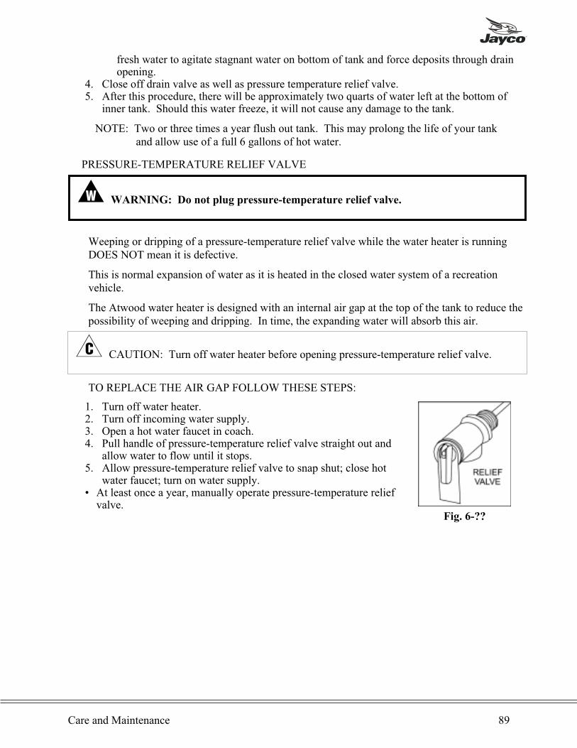
fresh water to agitate stagnant water on bottom of tank and force deposits through drainopening.
4. Close off drain valve as well as pressure temperature relief valve.5. After this procedure, there will be approximately two quarts of water left at the bottom of
inner tank. Should this water freeze, it will not cause any damage to the tank.
NOTE: Two or three times a year flush out tank. This may prolong the life of your tankand allow use of a full 6 gallons of hot water.
PRESSURE-TEMPERATURE RELIEF VALVE
� WARNING: Do not plug pressure-temperature relief valve.
Weeping or dripping of a pressure-temperature relief valve while the water heater is runningDOES NOT mean it is defective.
This is normal expansion of water as it is heated in the closed water system of a recreationvehicle.
The Atwood water heater is designed with an internal air gap at the top of the tank to reduce thepossibility of weeping and dripping. In time, the expanding water will absorb this air.
� CAUTION: Turn off water heater before opening pressure-temperature relief valve.
TO REPLACE THE AIR GAP FOLLOW THESE STEPS:
1. Turn off water heater.2. Turn off incoming water supply.3. Open a hot water faucet in coach.4. Pull handle of pressure-temperature relief valve straight out and
allow water to flow until it stops.5. Allow pressure-temperature relief valve to snap shut; close hot
water faucet; turn on water supply.• At least once a year, manually operate pressure-temperature reliefvalve.
Care and Maintenance 89
Fig. 6-??

When pressure-temperature relief valve discharges again, repeat above procedure. For apermanent solution, we recommend one of the following:
• Install a pressure relief valve in cold water inlet line to water heater and attach a drain linefrom valve to outside of coach. Set to relieve at 100-125 PSI.
• Install a diaphragm-type expansion tank in cold water inlet line. Tank should be sized toallow for expansion of approximately 15 oz. of water and pre-charged to a pressure equal towater supply pressure.
These devices can be obtained from a plumbing contractor or service center.
Air Conditioner
For proper operation of the air conditioner unit, it is important to clean and, if necessary, replacethe filters. The filters are made from long life non-allergenic natural fibers which can becleaned and reused, and which completely filter the circulated air when the air conditioner is inoperation. If the filters are not cleaned at regular intervals, they may become partially cloggedwith lint, dirt, grease, etc. A clogged filter will produce a loss of air volume and may eventuallycause an icing-up of the cooling (evaporator) coil. It is recommended that the filters be cleanedand changed at least every two weeks when the air conditioner is in operation.
� CAUTION: Do not operate your air conditioner for extended periods of time without thefilter installed. When the filter is not installed, the lint, dirt, grease, etc. That are normallystopped by the filter are now accumulating in the cooling coil. This not only leads to a loss ofair volume and a possible icing-up of the cooling coil, but could also result in serious damageto the operating components of the air conditioner. It is recommended that the filters becleaned and changed at least every two weeks when the air conditioner is in operation.
CLEANING AND/OR CHANGING THE FILTER:1. Remove the selector switch and thermostat knobs from the ceiling assembly.2. Remove the screws that secure the ceiling assembly shroud to the ceiling assembly.3. Lower the shroud and gently slide it off the control knob shafts.4. Take filters out and either clean or exchange with other filters.5. If the vehicle is equipped with a flush mount ceiling assembly, remove the four return air
grill screws. Remove filter from grill and either clean or exchange with new filter.
NOTE: If replacement filters are necessary, the filters can be purchased from most RV ProductsAuthorized Service Centers. It is recommended that spare filters be carried with the RV at alltimes to replace worn, torn or deteriorated filters.
90 Type C Owner’s Manual
Carbon Monoxide Detector
TESTING
� WARNING: DO NOT attempt to test the detector by any other means than using the
"test" button. DO NOT attempt to produce carbon monoxide to test the detector.
The CO detector should be tested weekly for proper operation:
1. Push the test button until the yellow LED lights and a short beep is heard for approximatelythree seconds.
2. Release button.
The detector will test itself for proper operation. Upon completion of the self-test, the alarm willsound and each of the LEDs will light for approximately _ second. The detector will thenresume normal operation.
BATTERY REPLACEMENT
Under normal operating conditions, the battery will last approximately one year. The detectorhas a low battery monitor circuit which will cause the detector to make a chirping sound thenthe red LED to flash every 30-40 seconds for a minimum of seven (7) days indicating thebattery is low. Replace the battery when this occurs. Use only 9-volt batteries for the COdetector replacement.
� WARNING: Use only the batteries specified for replacement. Use of different
batteries may have a detrimental effect on the CO detector.
CLEANING
Use the following procedure to clean the CO detector:
1. Remove the detector from the mounting plate by rotating the detector in the direction of the"OFF" arrow on the cover.
2. Clean the interior of the detector by using a vacuum cleaner hose and vacuuming through theopenings around the perimeter of the detector.
3. Wipe the outside of the detector with a damp cloth.4. Replace detector.5. Test detector using the testing procedure.
UNIT REPLACEMENT
The CO detector should be replaced every six years.
Additional information is supplied in the manual published by the manufacturer of theequipment.
Care and Maintenance 91
Slideout Preventative Maintenance
Your Power Gear slideout system has been designed to require very little maintenance. Toensure a long life of your slideout system, read and follow these simple procedures.
� CAUTION: Do not work on your system unless the battery is disconnected.
• When the room is out, visually inspect the inner slide rail assemblies (see Fig. 3-9). Check forexcess buildup of dirt or other foreign material; remove any debris that may be present.
• If the system squeaks or makes any noises apply a coat of light weight oil to the drive shaftand roller areas. Remove any excess oil to prevent buildup of dirt and debris.
• If you have any problems or questions consult your local Jayco dealer or call Power Gear1-800-334-4712
Window Treatments
The window treatments of your recreation vehicle may include metal mini blinds, pleatedshades, and/or drapes. Refer to the following guidelines for cleaning.
Window Treatment Light Cleaning Extensive Cleaning
Mini Blinds Dust or VacuumMay be removed and washedwith a mild detergent and
warm water
Pleated Shades VacuumA professional dry cleaningservice is recommended.
Privacy or cab Area Draperies Vacuum Professionally Dry Clean.
Shower Curtain and Liner
The shower curtain is made of a cotton or cotton/polyester material and should be dry cleaned.The shower curtain liner should be cleaned as you would clean your own shower curtain liner athome.
Furniture
To clean the sofa, dinette, J-Steel and/or chair cushion covers, frequently vacuum or lightlybrush to remove dust and dirt. Vinyl can be wiped clean with a damp cloth.
The furniture fabrics are treated with a salt-based chemical making them fire retardant. All itemstreated with this chemical should be professionally dry cleaned. Spot cleaning is notrecommended as the water may leave spots on the fabric.
92 Type C Owner’s Manual
Cushions
� CAUTION: Do not dry clean vinyl components. Do not remove covers for dry cleaning.
If the cushions are dry cleaned, the vinyl on the reverse side of the cushion will shrink, becomehard and crack. Vacuum the fabric and wipe the vinyl surfaces. The fabric side can be gentlysteam cleaned on the cushions or mats, if necessary.
All dinette and bed mat covers are treated with stain protector. Vacuum the cover with a brushattachment periodically to remove dirt.
Paneling
The wall paneling in your new Jayco is a vinyl covered panel. If deep scratches occur, puttysticks can be used to cover scratches on wood surfaces. These can be obtained from hardwarestores and lumber yards. For decor paneling, replacement vinyl covering can be purchased ifrepairs are needed. Contact your dealer's parts department.
To clean, use a mild solution of soap and lukewarm water with a soft sponge or cloth. DO NOTuse abrasive cleaners. It may cause the vinyl to scratch and become dull. Grease spots andstubborn dirt can be cleaned with an all-purpose spray cleaner. DO NOT use cleaners thatcontain bleach.
Floor
To care for the vinyl floor covering, use a damp mop with water and a mild cleaner. DO NOTSOAK THE FLOORING. Use care to avoid wetting the carpet edges.
Bathroom Tubs and Lavatory Sinks
The bathtub is made of ABS plastic material. Do not use abrasive cleaners as they may scratchsurfaces. Use a mild detergent soap and water, Bon Ami or Bar Keeper's Friend to clean the tubsurface.
For any type of repair work, see your authorized Jayco dealer.
Hardware and Sink or Shower Fixtures
Use mild dish soap and water to clean these fixtures. Never use harsh chemicals or sprays. Amild solution of vinegar and water works well to remove hard water spots and stains from thesink or shower fixtures.
Carpeting
If your mini-motorhome contains carpeting, vacuum frequently. Professional steam cleaning fortough and deep stains is recommended. Use spot removers for minor spills. Always test carpetfor colorfastness in an inconspicuous area before using any product.
NOTE: Avoid chemical cleaners. Do not permit cleaners to touch carpet or fabrics.
Care and Maintenance 93

Counter Top
Made of high-pressure laminate, the counter top is easy to keep clean. Glass rings, food spills,water spots and smudges usually wipe off with a damp sponge. Stains can be removed with ageneral-purpose spray cleaner. Stubborn stains can sometimes be removed by squeezing freshlemon juice over the stain, allowing the juice to soak for approximately forty-five minutes, andthen sprinkling baking soda over the lemon juice and rubbing the stain with a soft cloth.
MAINTENANCE CHECKLIST
Below is a list of suggested maintenance items to follow at specific intervals for optimumperformance and operation of your Jayco RV. This list is meant to be a supplement to themaintenance items of the chassis manufacturer's owner's manual. Please add these items to yourmaintenance routine.
� WARNING: It is important that you carefully read your chassis manufacturer's
owner's manual maintenance items. The following list is only a supplement to that list.
Failure to follow both lists could be detrimental to the proper operation of your
recreation vehicle or cause failures which can cause property damage and personal
injury.
PRIOR TO FIRST TRIP] Check LP gas lines for leaks.] Test carbon monoxide detector (Generator/Generator Prep option only.)] Test LP gas detector.] Sanitize fresh water system.] Open all windows and the door and start the furnace. Leave the windows and door open andthe furnace on until all fumes fully dissipate.
EACH TRIP] Test LP gas detector.] Check RV battery water level. (If equipped with battery.)] Check running lights.
DAILY] Recharge RV battery after each use.] Ensure LP gas detector operation light is green in color.
WEEKLY] Test LP gas detector.
MONTHLY] Check fire extinguisher pressure. Refer to the fire extinguisher label for specific instructions.] Test the ground fault circuit interrupter (GFCI)
94 Type C Owner’s Manual

EVERY THREE MONTHS OR 3,000 MILES] Vacuum around LP Burner and pilot light areas.] Compare water heater pilot flame with ideal flame. Refer to the water heater owner's manualfor ideal flame. Clean and adjust as necessary.
] Compare refrigerator pilot flame with ideal flame. Refer to the refrigerator owner's manual forideal flame. Clean and adjust as necessary. (RV type refrigerator only)
] Inspect refrigerator door seals.] Inspect refrigerator combustion seals. (RV type refrigerator only)] Check LP gas lines for leaks.
EVERY THREE MONTHS OR 3,000 MILES (CONTINUED)] Inspect LP cylinders for rust pits, gouges, scrapes or sharp dents. Repaint cylinders if rust ispresent.
] Drain and sanitize fresh water system.] Check, clean, tighten and lubricate battery cables.
EVERY FOUR MONTHS OR 4,000 MILES] Flush out water heater tanks.
EVERY SIX MONTHS OR 6,000 MILES] Clean drains with approved drain cleaners.] Check pipe connections for tightness. Tighten if necessary.] Lubricate all moving parts on the entrance steps.] Lubricate entrance and baggage door locks.] Inspect wheels for cracks, dents or distortion.] Inspect and reseal all sealant and putty tape.] Lubricate the elevating gear on the television antenna.] Lubricate the bearing surface between the rotating gear housing and the base plate on thetelevision antenna.
] Lubricate the rubber quad ring on the elevating shaft located on the television antenna.
EVERY YEAR OR 12,000 MILES] Lubricate moving parts on the awning hardware. (Awning option only.)] Manually operate the pressure-temperature control lever or dial to the lowest possible positionon the water heater.
] Clean city water entry strainer.] Check demand tank vent for obstructions.] Check water pump connections and mountings for tightness.] Vacuum the LP gas detector cover.] Rotate Fluorescent tubes in the light fixtures.] Clean absorption refrigerator flue. (RV type refrigerator only.)] Replace battery on the carbon monoxide detector. (Generator/Generator Prep option only.)] Have LP gas system inspected and serviced by a qualified technician.] Inspect and seal corners at the threshold of the entrance door.] Have the refrigerator inspected and serviced by a qualified technician.] Have furnace inspected and serviced by a qualified technician.
EVERY SIX YEARS] Replace carbon monoxide detector (Generator/Generator Prep option only.)
Care and Maintenance 95

Chapter 7
OPTIONS
NOTE: Information in this chapter may not necessarily apply to your unit. For somemodels, optional equipment may have been added as your vehicle was beingbuilt. There may be some information here that is standard equipment for themodel of mini-motorhome that you own. This chapter contains information toaid in the operation of such equipment.
This owner’s manual covers basic optional equipment operation only. Make
sure you read all manuals provided by the manufacturer which are included
with each recreation vehicle. These manuals provide extensive information
for your safety and the proper operation of the equipment.
GENERATOR
Before operating the generator set, read the manufacturer’s owner’s manual and becomefamiliar with it and the equipment. Safe and efficient operation can be achieved only if the unitis properly operated and maintained. Manu accidents are caused by failure to followfundamental rules and precautions.
FUEL AND FUMES ARE FLAMMABLE
Fire, explosion, and personal injury can result from improper practices.
• Do not smoke or allow an open flame or spark-producing equipment near the generator set orfuel tank.
• Inspect the fuel lines and connections daily for leaks per the maintenance schedule.
EXHAUST GASES ARE DEADLY• Never sleep in the vehicle with the generator set running unless vehicle is equipped with anoperating carbon monoxide detector.
• Inspect exhaust system daily for leaks per the maintenance schedule. Do not use enginecooling air to heat a compartment.
• Never operate the generator set inside a building or in an area where exhaust gases couldaccumulate, such as near a wall or snow bank, or in high grass. When parking, make sure theexhaust outlet is not obstructed. Make sure the generator set is well ventilated.
ELECTRICAL SHOCK CAN CAUSE SEVERE PERSONAL INJURY OR DEATH• Disconnect the negative (-) cable at the starting battery before removing protective shields ortouching electrical equipment. Use rubber insulative mats placed on dry wood platforms onthe ground or over floors that are metal or concrete when around electrical equipment. Do notwear damp clothing (particularly wet shoes) or allow skin surfaces to be damp when handlingelectrical equipment.
• Use extreme caution when working on electrical components. High voltages can cause injuryor death.
• Tag remote or open switches to avoid accidental closure or starting.• DO NOT CONNECT GENERATOR SET DIRECTLY TO ANY BUILDING ELECTRICALSYSTEM. Hazardous voltages can flow from the generator set into the utility line. Thiscreates a potential for electrocution or property damage. Connect only through an approveddevice and after building main switch is open. Consult an electrician in regard to emergencypower use.
96 Type C Owner’s Manual
MOVING PARTS CAN CAUSE SEVERE PERSONAL INJURY OR DEATH• Before starting work on the generator set, disconnect negative (-) cable at the battery. Thiswill prevent accidental arcing or starting.
• Keep your hands away from moving parts.• Make sure that fasteners on the generator set are secure. Tighten supports and clamps, keepguards in position over fans, etc.
• Do not wear loose clothing or jewelry while working on generator sets, because they canbecome caught in moving parts. Jewelry can short out electrical contacts and cause shock orburning.
• If adjustment must be made while the unit is running, use extreme caution around hotmanifolds, moving parts, etc.
General Safety Precautions
• Wear safety glasses and protective clothing when servicing batteries. DO NOT SMOKEwhile servicing batteries. Lead-acid batteries emit a highly explosive hydrogen gas that can beignited by electrical arcing or by smoking.
• Have a fire extinguisher rated ABC near by. Maintain extinguisher properly and becomefamiliar with its use.
• Benzene and lead, found in some gasoline, have been identified by some state and federalagencies as causing cancer or reproductive toxicity. When checking, draining or addinggasoline, take care not to ingest, breathe the fumes, or contact gasoline.
• Used engine oils have been identified by some state or federal agencies as causing cancer orreproductive toxicity. When checking or changing engine oil, take care not to ingest, breathethe fumes, or contact used oil.
• Remove all necessary grease and oil from the unit. Accumulated grease and oil can causeoverheating and engine damage, which presents a potential fire hazard.
• Do not store anything in the generator set compartment such as oil or gas cans, oily rags,chains, wooden blocks, portable propane cylinders, etc. A fire could result or the generator setoperation (cooling, noise and vibration) may be adversely affected. Keep the compartmentfloor clean and dry.
• Do not work on this equipment when mentally or physically fatigued, or after consuming anyalcohol or drug that makes the operation of equipment unsafe.
Fuel Recommendations
� WARNING: Gasoline an d LP Gas are highly flammable fuels and can cause severe
personal injury or death. Do not smoke if you smell gas or gasoline or are near fuel
tanks or fuel-burning equipment or are in an area sharing ventilation with such
equipment. Keep flames, sparks, pilot lights, electrical arcs and arc-producing
equipment and all other sources of ignition well away. Keep a type ABC fire
extinguisher in the vehicle.
GASOLINE MODELS
Use clean, fresh unleaded gasoline having a minimum octane rating (anti-knock index) of 87.
During some times of the year only mandated “oxygentated” gasolines may be available. Theseare acceptable for use, but not preferable. Leaded gasoline may be used but will result in theextra maintenance required for removing combustion chamber and spark plug deposits. Do not
Options 97

use gasoline or gasoline additives (deicers) containing methanol because methanol can becorrosive to fuel system components.
� CAUTION: DO not use gasoline or gasoline additives containing methanol becausemethanol can be corrosive to fuel system components. Avoid using highly leaded gasolinesand lead additives because of the extra engine maintenance that will be required.
“Genset” Control Panel
The genset control panel (Fig. 7-1) Is located behindthe access cover on the genset. It has the followingfeatures:
START-STOP Switch (Fig. 7-1 - #1) - This is arocker switch which returns to its neutral positionwhen you let go. Hold it in the START position tocrank and start the genset and push it momentarily tothe STOP position to stop the genset.
Control Fuse - This fuse provides short circuitprotection for the control and remove control circuits.
Line Circuit Breaker - The line circuit breakerprotects the AC power leads connected to the gensetfrom overloads and equipment short circuits.
Remote Control
The vehicle has a remote control panel (Fig. 7-2)inside the door for controlling the genset operation.
The a START-STOP switch has a lamp that lights toindicate when the genset is running (which may nototherwise be obvious, especially when the vehicle ismoving). The remote control also has an hour meterand a battery condition meter. The hour meterrecords genset operating time in hours. Use it forperiodic maintenance as a record of operating time.The battery condition meter indicates whethervoltage across the 12-volt DC control system andbattery is normal. If the indicator consistently staysabove or below the normal zone, see Battery Careunder Periodic Maintenance.
98 Type C Owner’s Manual
Fig. 7-1
Fig. 7-2

Starting and Stopping
� WARNING: EXHAUST GAS IS DEADLY! Exhaust gases contain carbon
monoxide, an odorless and colorless gas. Carbon monoxide is poisonous and can
cause unconsciousness and death. Symptoms of carbon monoxide poisoning include:
Dizziness Throbbing in Temples
Nausea Muscular Twitching
Headache Vomiting
Weakness and Sleepiness Inability to Think Coherently
IF YOU OR ANYONE ELSE EXPERIENCE ANY OF THESE SYMPTOMS, GET
OUT INTO THE FRESH AIR IMMEDIATELY. If symptoms persist, seek medical
attention. Shut down the genset and do not operate it until it has been inspected and
repaired.
Never sleep in the vehicle with the genset running unless the vehicle is equipped with a
working carbon monoxide detector. Primary protection against inhaling carbon
monoxide, however, is the proper installation of the exhaust system and the daily
(every eight hour) inspection for visible and audible exhaust system leaks.
PRE-START CHECKS
Before the first start of the day and after every eight hours of operation, perform themaintenance instructed in OIL LEVEL CHECK AND GENERAL INSPECTION underPeriodic Maintenance. Keep a log of maintenance and the hours run and perform anymaintenance that may be due. Also, see Genset Break-in, Exercise and Storage to return thegenset to service if the vehicle has been in storage.
STARTING
The genset can be started and stopped from the genset control panel or from the remote controlpanel inside the vehicle (if so equipped).
1. Perform the PRE-START CHECKS and turn off the air conditioner and other large electricalloads. Open the manual shutoff valve at the LP Gas container if this is an LP Gas genset.
2. Push and hold the or remote START switch until the genset starts. (The remote STARTswitch inside the vehicle should have a lamp which lights to indicate that the genset hasstarted and is running).
� CAUTION: Cranking the starter for longer than 10 seconds at a time can overheat anddamage the starter. Do not crank for more than 10 seconds at a time and wait at least 30seconds before trying again.
Secure the access cover as soon as the engine starts up when starting the at the genset controlpanel.
Options 99

� CAUTION: Proper engine cooling requires that the access cover be secured duringoperation. Also, hot engine parts can cause severe burns. Always secure the access cover assoon as the engine starts up.
1. For top performance and engine life, especially in colder weather, let the engine warm up forat least two minutes before connecting the genset to the vehicle electrical loads (appliances).See Powering Equipment.
2. Check for fuel and exhaust leaks. Stop the genset immediately if there is a fuel or exhaustleak and have it repaired before continuing operation.
3. See Troubleshooting if the engine does not crank
STOPPING1. Turn off the air conditioner and other large electrical loads and let the genset run two minutes
before stopping it. This allows the engine to cool down, reducing the incidence of backfiringand engine run-on.
2. Push the STOP switch momentarily.
”Genset” Loading
The AC output of the genset powers the vehicle air conditioner, the DC converter/batterycharger and the appliances that may be plugged into the electrical outlets of the vehicle. Howmuch electrical equipment (power consuming appliances) can be operated at one time dependsupon how much power is available from the genset. If the genset is “overloaded”, either thegenset will stall or its circuit breaker(s) will trip.
To get an idea of how much equipment can be operated at one time add up the watt ratings ofthe individual appliances that are likely to be used at the same time and compare the sum to thekW (kilowatt) rating of the genset. Use table 2 or the ratings on the appliances themselves (if somarked) to obtain the appliance watt values. Note that 1kW = 1,000 watts. If powerconsumption, as totaled up, exceeds genset power output, you may have to consider operatingsome appliances in sequence, one after another, rather than all at the same time.
Note that when the genset is loaded nearly to full power, it is possible that it may stall when theair conditioner (or other large load) “cycles on”. The reason for this is that for a brief momentat startup a motor draws up to three times the power stated on its nameplate. You may,therefore, have to consider operating some appliances at times when the air conditioner or otherlarge motor load is not “On”.
Note also that as altitude increases air density decreases, causing genset engine power todecrease (even when the altitude adjust knob is set correctly - see Varying OperatingConditions). Power decreases approximately 3.5 percent of rated power each 1000 feet (305 M)of increase in elevation above sea level. See Table 3 for the results of calculations for a typicalgenset. Therefore, at higher altitudes consider operating fewer appliances at the same time.
Electrical equipment and tools must be properly grounded and in good working condition.
� WARNING: Electrical shock can cause severe personal injury or death. Read and
follow the equipment and tool manufacturer’s instructions and warnings.
100 Type C Owner’s Manual
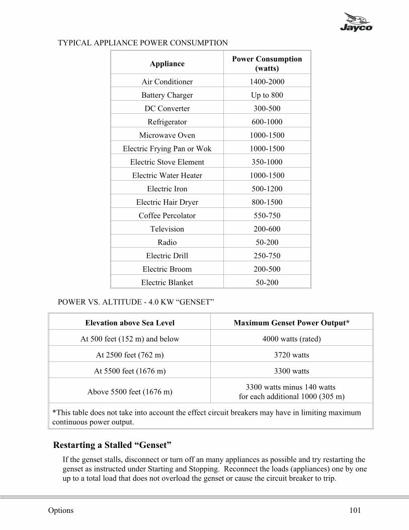
TYPICAL APPLIANCE POWER CONSUMPTION
AppliancePower Consumption
(watts)
Air Conditioner 1400-2000
Battery Charger Up to 800
DC Converter 300-500
Refrigerator 600-1000
Microwave Oven 1000-1500
Electric Frying Pan or Wok 1000-1500
Electric Stove Element 350-1000
Electric Water Heater 1000-1500
Electric Iron 500-1200
Electric Hair Dryer 800-1500
Coffee Percolator 550-750
Television 200-600
Radio 50-200
Electric Drill 250-750
Electric Broom 200-500
Electric Blanket 50-200
POWER VS. ALTITUDE - 4.0 KW “GENSET”
Elevation above Sea Level Maximum Genset Power Output*
At 500 feet (152 m) and below 4000 watts (rated)
At 2500 feet (762 m) 3720 watts
At 5500 feet (1676 m) 3300 watts
Above 5500 feet (1676 m)3300 watts minus 140 watts
for each additional 1000 (305 m)
*This table does not take into account the effect circuit breakers may have in limiting maximumcontinuous power output.
Restarting a Stalled “Genset”
If the genset stalls, disconnect or turn off an many appliances as possible and try restarting thegenset as instructed under Starting and Stopping. Reconnect the loads (appliances) one by oneup to a total load that does not overload the genset or cause the circuit breaker to trip.
Options 101
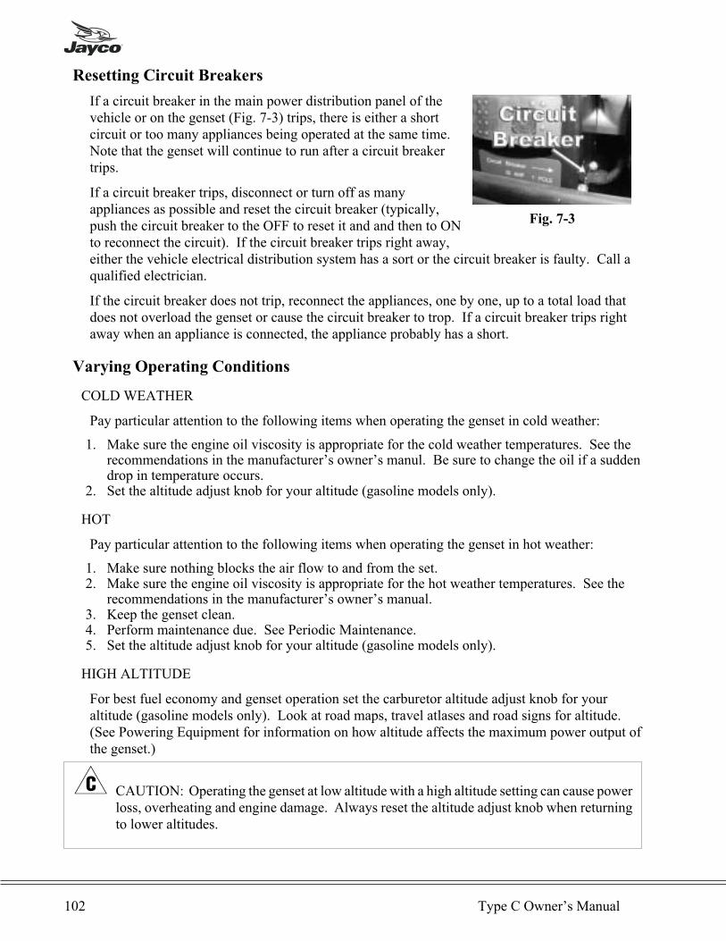
Resetting Circuit Breakers
If a circuit breaker in the main power distribution panel of thevehicle or on the genset (Fig. 7-3) trips, there is either a shortcircuit or too many appliances being operated at the same time.Note that the genset will continue to run after a circuit breakertrips.
If a circuit breaker trips, disconnect or turn off as manyappliances as possible and reset the circuit breaker (typically,push the circuit breaker to the OFF to reset it and and then to ONto reconnect the circuit). If the circuit breaker trips right away,either the vehicle electrical distribution system has a sort or the circuit breaker is faulty. Call aqualified electrician.
If the circuit breaker does not trip, reconnect the appliances, one by one, up to a total load thatdoes not overload the genset or cause the circuit breaker to trop. If a circuit breaker trips rightaway when an appliance is connected, the appliance probably has a short.
Varying Operating Conditions
COLD WEATHER
Pay particular attention to the following items when operating the genset in cold weather:
1. Make sure the engine oil viscosity is appropriate for the cold weather temperatures. See therecommendations in the manufacturer’s owner’s manul. Be sure to change the oil if a suddendrop in temperature occurs.
2. Set the altitude adjust knob for your altitude (gasoline models only).
HOT
Pay particular attention to the following items when operating the genset in hot weather:
1. Make sure nothing blocks the air flow to and from the set.2. Make sure the engine oil viscosity is appropriate for the hot weather temperatures. See the
recommendations in the manufacturer’s owner’s manual.3. Keep the genset clean.4. Perform maintenance due. See Periodic Maintenance.5. Set the altitude adjust knob for your altitude (gasoline models only).
HIGH ALTITUDE
For best fuel economy and genset operation set the carburetor altitude adjust knob for youraltitude (gasoline models only). Look at road maps, travel atlases and road signs for altitude.(See Powering Equipment for information on how altitude affects the maximum power output ofthe genset.)
� CAUTION: Operating the genset at low altitude with a high altitude setting can cause powerloss, overheating and engine damage. Always reset the altitude adjust knob when returningto lower altitudes.
102 Type C Owner’s Manual
Fig. 7-3
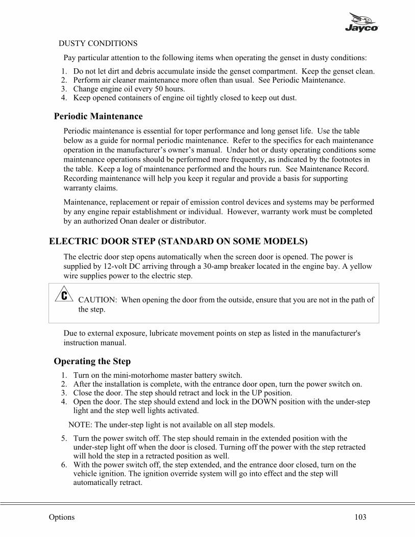
DUSTY CONDITIONS
Pay particular attention to the following items when operating the genset in dusty conditions:
1. Do not let dirt and debris accumulate inside the genset compartment. Keep the genset clean.2. Perform air cleaner maintenance more often than usual. See Periodic Maintenance.3. Change engine oil every 50 hours.4. Keep opened containers of engine oil tightly closed to keep out dust.
Periodic Maintenance
Periodic maintenance is essential for toper performance and long genset life. Use the tablebelow as a guide for normal periodic maintenance. Refer to the specifics for each maintenanceoperation in the manufacturer’s owner’s manual. Under hot or dusty operating conditions somemaintenance operations should be performed more frequently, as indicated by the footnotes inthe table. Keep a log of maintenance performed and the hours run. See Maintenance Record.Recording maintenance will help you keep it regular and provide a basis for supportingwarranty claims.
Maintenance, replacement or repair of emission control devices and systems may be performedby any engine repair establishment or individual. However, warranty work must be completedby an authorized Onan dealer or distributor.
ELECTRIC DOOR STEP (STANDARD ON SOME MODELS)
The electric door step opens automatically when the screen door is opened. The power issupplied by 12-volt DC arriving through a 30-amp breaker located in the engine bay. A yellowwire supplies power to the electric step.
� CAUTION: When opening the door from the outside, ensure that you are not in the path ofthe step.
Due to external exposure, lubricate movement points on step as listed in the manufacturer'sinstruction manual.
Operating the Step
1. Turn on the mini-motorhome master battery switch.2. After the installation is complete, with the entrance door open, turn the power switch on.3. Close the door. The step should retract and lock in the UP position.4. Open the door. The step should extend and lock in the DOWN position with the under-step
light and the step well lights activated.
NOTE: The under-step light is not available on all step models.
5. Turn the power switch off. The step should remain in the extended position with theunder-step light off when the door is closed. Turning off the power with the step retractedwill hold the step in a retracted position as well.
6. With the power switch off, the step extended, and the entrance door closed, turn on thevehicle ignition. The ignition override system will go into effect and the step willautomatically retract.
Options 103
� WARNING: If the vehicle is driven with the step in the extended position, there is the
possibility of causing major damage to both the step and the vehicle.
7. Turn the vehicle ignition off and open the door. The step will extend and lock in the DOWNposition.
� WARNING: If the door is opened and closed without allowing the step to fully extend
and lock in the DOWN position, the step will retract and lock in the UP position. When
the door is reopened, the step will not extend. The power switch must be turned on for
the step to extend.
8. The LAST OUT feature is only operative the first time the door is opened after the vehicleignition is turned off.
When the vehicle ignition is on, the step will always activate with the door movement,regardless of the switch position.
� WARNING: Be safe, look before you leap!
HEATED HOLDING TANKS
With the heated tank option, a pad will be glued to the exterior bottom side of the holding tank.Heat is supplied by 12-volt DC power through the heating element built into the pad.Approximately 6-amps of energy per pad is consumed and fused through the 12-volt powersupply board. Switches to turn heat pads on or off are located on an interior wall in or near thebathroom.
POWER TO HEATING PADS SHOULD BE TURNED OFF UNTIL:1. Water is in the holding tank.2. Temperature drops to 32° (0° C).3. Mini-motorhome is parked, setup and all attachments performed.
NOTE: Turn heat pads off when dumping and draining tanks.
An internal thermostat is built into components of the heat pad to assist in energy conservation.
BBQ GRILL
An option for your mini-motorhome is a BBQ Grill. This grill is for use outside of themini-motorhome and comes with a bracket to attach to the side of the vehicle. The following listwill supply basic operations for the grill. Be sure to read all instructions included with the grill.
1. Install the grill bracket on the side of the mini-motorhome mounting bracket. Make sure thatit is securely in place.
2. Place the BBQ grill into the bracket. (Fig. 7-4)
104 Type C Owner’s Manual

3. Attach the fuel hose to the grill and the LP gas connection located under the mini-motorhomeby using the "Quick-Coupler" instruction as follows (Fig. 7-5):• Place the handle in the "OFF" position and push back the sleeve. Valve handle must be inthe "OFF" position to make the connection. (Fig. 7-6)
• Insert the plug and release the sleeve. (Fig. 7-6)• Push plug until the sleeve snaps forward, locking the plug into the socket. (Fig. 7-7)• Turn handle to "ON" position to turn gas on. (Fig. 7-8)
4. Open the lid to the BBQ Grill.5. Using an electric match, light the grill using the following procedures:
• Light the electric match.• Insert it into the middle slot on the bottom of the BBQ Grill.• On the grill control knob (Fig. 7-5), depress and turn the knob to the desired temperature.• The grill should light at this point.
6. If the grill does not light, turn the gas off, wait five minutes and repeat the above steps.7. Use the temperature control knob to adjust the grill to the desired temperature.
The BBQ Grill grate is coated with standard grill enamel and can be cleaned as you would agrill at home. Underneath the grate, there is a heat diffuser. This is formed and ventilated todistribute the heat from the burner. Do not use lava rocks in this grill.
To disconnect the BBQ grill, turn the temperature control to the "OFF" position. Reverse theabove fuel hose hookup procedures. Wait until the grill is completely cooled, and then store it inthe supplied carrying case. This carrying case will ONLY accommodate a cool grill. The grillcarrying case has a pocket for accessories such as the fuel hose in the lid. The bracket will notfit inside the carrying case and will need to be stored in a separate location.
� CAUTION: The BBQ grill must be COMPLETELY cooled before storing to avoiddamaging the carrying case.
Options 105
Fig. 7-5Fig. 7-4
Fig. 7-6 Fig. 7-7 Fig. 7-8
POWER MIRRORS
A control panel is placed in the mounting panel of the mirror on the driver's side. The system ispowered by 12-volt DC with fuse located under the dash, 1-amp in line.
TO OPERATE:1. Center switch is in the "OFF" position when you can observe both letters (R/L)2. Move center tab to extreme right or left, viewing only one letter.3. Power is now on.4. Press any arrow in the direction you wish to move the mirror.5. Place tab to center to turn switch off.
HITCH
Your mini-motorhome is designed to be a recreation vehicle, however it does have towingcapabilities as well as limitations. A class 3 hitch receiver is available with a 3,500# (1588kilograms) gross weight capacity. A variety of extender bars of different ratings are available.Remember the limit of weight on the hitch and chassis.
The above warning label is attached to your mini-motorhome on the exterior near the hitchreceiver bar and in the interior adjacent to or immediately below the RVIA Weight InformationLabel. This is typically on the back of an interior cabinet door in the kitchen. For your safety,please review and understand all towing and braking capacities of your vehicle. For addedinformation, consult with your chassis dealer or manufacturer.
106 Type C Owner’s Manual
WARNING!YOUR MOTORHOME CHASSIS IS RATED FOR TOWING OPERATION AT GVWR NOT GCWR. CONSULT YOURCHASSIS OWNER’S MANUAL(S) FOR SPECIFIC WEIGHING INSTRUCTIONS AND TOWING GUIDELINES. THEBRAKING CAPACITY OF YOUR MOTORHOME IS NOT NECESSARILY AS GREAT AS THE TOWING CAPACITY.SEPARATE BRAKING SYSTEMS SHOULD BE USED FOR CONTROL OF A TOWED VEHICLE, (AUTO, TRAILER,BOAT, ETC.), BEHIND THE MOTORHOME. IF THE TOWED BEHICLE MEETS OR EXCEEDS THE MINIMUM WEIGHTAS DETERMINED BY THE CHASSIS MANUFACTURER, (THIS MINIMUM WEIGHT RATING WILL VARY BY CHASSISAND CHASSIS MANUFACTURER), CONTACT YOUR CHASSIS DEALER OR MANUFACTURER FOR ASSISTANCE INDETERMINING WHETHER A SEPARATE BRAKING SYSTEM IS RECOMMENDED AND WHAT LIMITS THERE AREFOR YOUR TOWING COMBINATION AND TRAVELING SAFETY.
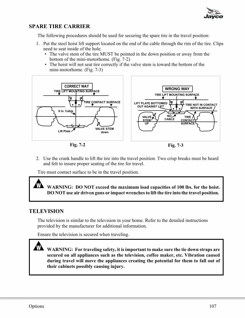
SPARE TIRE CARRIER
The following procedures should be used for securing the spare tire in the travel position:
1. Put the steel hoist lift support located on the end of the cable through the rim of the tire. Clipsneed to seat inside of the hole.• The valve stem of the tire MUST be pointed in the down position or away from thebottom of the mini-motorhome. (Fig. 7-2)
• The hoist will not seat tire correctly if the valve stem is toward the bottom of themini-motorhome. (Fig. 7-3)
2. Use the crank handle to lift the tire into the travel position. Two crisp breaks must be heardand felt to insure proper seating of the tire for travel.
Tire must contact surface to be in the travel position.
� WARNING: DO NOT exceed the maximum load capacities of 100 lbs. for the hoist.
DO NOT use air driven guns or impact wrenches to lift the tire into the travel position.
TELEVISION
The television is similar to the television in your home. Refer to the detailed instructionsprovided by the manufacturer for additional information.
Ensure the television is secured when traveling.
� WARNING: For traveling safety, it is important to make sure the tie down straps are
secured on all appliances such as the television, coffee maker, etc. Vibration caused
during travel will move the appliances creating the potential for them to fall out of
their cabinets possibly causing injury.
Options 107
CORRECT WAYTIRE LIFT MOUNTING SURFACE
TIRE CONTACT SURFACE
VALVE STEMdownLift Plate
6 in. Cable
Fig. 7-2
VALVESTEM
UP
LIFT PLATE BOTTOMEDOUT AGAINST LIFT
NOCABLE
TIRE LIFT MOUNTING SURFACE
TIRE NOT IN CONTACTWITH SURFACE
TIRECONTACTSURFACE
WRONG WAY
Fig. 7-3

EXTERIOR PRIVACY SHIELD
An optional privacy shield is available for the mini-motorhome. Use of the privacy shield willallow full access to the cab area from the inside while providing privacy inside the vehicle. Thisprivacy shield hooks over the passenger and driver side doors and is notched out toaccommodate the side mirrors. To secure the privacy shield in place, there are magnets sewninto the canvas for attaching it to the metal cab. The windshield wipers will also help to hold itin place.
RV DIGITAL SATELLITE SYSTEM
The satellite system in the RV is similar to the satellite system in your home. Refer to thedetailed instructions provided by the manufacturer for additional information.
108 Type C Owner’s Manual
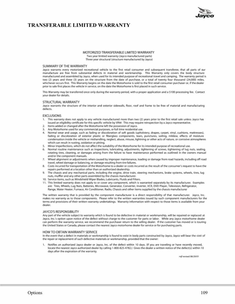
TRANSFERABLE LIMITED WARRANTY
Options 109
110 Type C Owner’s Manual

LIMITED WARRANTY TRANSFER APPLICATION
Options 111
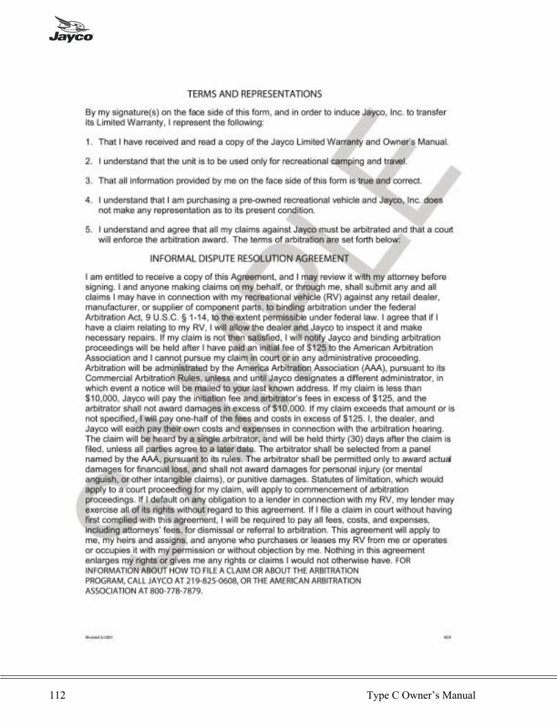
112 Type C Owner’s Manual
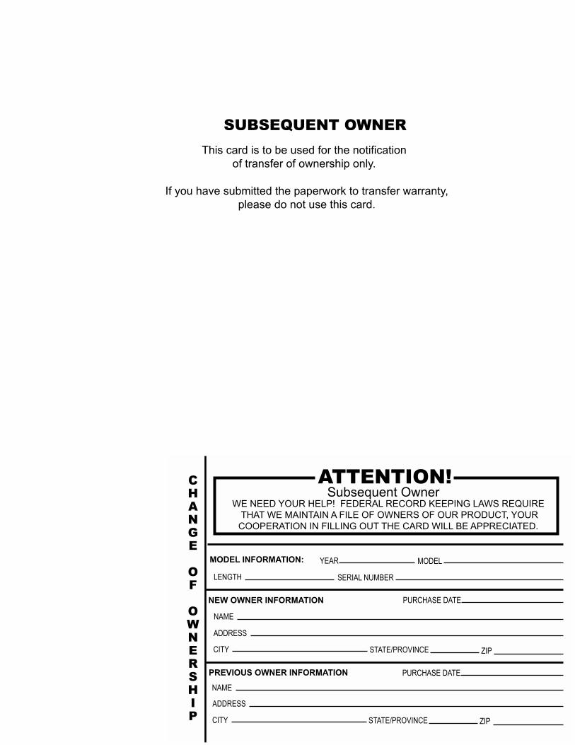
ATTENTION!Subsequent Owner
WE NEED YOUR HELP! FEDERAL RECORD KEEPING LAWS REQUIRE
THAT WE MAINTAIN A FILE OF OWNERS OF OUR PRODUCT, YOUR
COOPERATION IN FILLING OUT THE CARD WILL BE APPRECIATED.
MODEL INFORMATION: YEAR MODEL
LENGTH SERIAL NUMBER
NEW OWNER INFORMATION
NAME
ADDRESS
CITY STATE/PROVINCE ZIP
PREVIOUS OWNER INFORMATION PURCHASE DATE
CHANGE
OF
OWNERSHIP
NAME
ADDRESS
CITY STATE/PROVINCE ZIP
PURCHASE DATE
SUBSEQUENT OWNER
This card is to be used for the notification
of transfer of ownership only.
If you have submitted the paperwork to transfer warranty,
please do not use this card.
NO POSTAGENECESSARY
IF MAILEDIN THE
UNITED STATES
BUSINESS REPLYMAILFIRST-CLASS MAIL PERMIT NO. 21 MIDDLEBURY IN
POSTAGE WILL BE PAID BY THE ADDRESSEE
Jayco, Inc.
P.O. Box 460Middlebury, IN 46540-9904

NOTES

NOTES

NOTES
WELCOME TO THE JAYCO FAMILY!
As the owner of a new Jayco recreation vehicle we are proud to welcomeyou to our growing family.
All Jayco RV homes are built with care, under the watchful eye of ourQuality Assurance program. And it is our sincere wish that you will have alifetime of fun times with your new Jayco.
We are pleased you chose Jayco and want to do everything possible tomake sure you stay as happy with your Jayco RV home as you were on the dayyou bought it.
We work closely with Jayco dealers to provide customer service for you.We honestly feel that Jayco dealers are on the whole the best in the business.And with nearly 300 of them in the U. S. and Canada, you should never be toofar from help if you ever need it.
In the months and years to come we hope you will become aclose member of the Jayco family. One way to enjoy yourJayco even more is through our owner’s club - The JafariInternational Travel Club. It is lots of fun and a great way tomeet other members of the Jayco family. If you areinterested, please talk to your dealer about the “flight” in yourarea, or write to us directly and we will be in touch.
From Jayco’s family to yours: “Welcome Home!”
903 South Main Street • P.O. Box 460 • Middlebury, IN 46540


