12
WHITE PAPER White Paper: Building next- generation sheet metal CAM Version 1.0 Dec, 2013
W
HI
TE
P
AP
ER
Title
Subtitle
Version 0.0 Month Year
White Paper: Building next-
generation sheet metal CAM
Version 1.0
Dec, 2013

2
Copyright Notice
© Geometric Limited. All rights reserved.
No part of this document (whether in hardcopy or electronic form) may be reproduced, stored in a retrieval
system, or transmitted, in any form or by any means, electronic, mechanical, photocopying, recording, or
otherwise, to any third party without the written permission of Geometric Limited. Geometric Limited
reserves the right to change the information contained in this document without prior notice.
The names or trademarks or registered trademarks used in this document are the sole property of the
respective owners and are governed/ protected by the relevant trademark and copyright laws.
This document is provided by Geometric Limited for informational purposes only, without representation or
warranty of any kind, and Geometric Limited shall not be liable for errors or omissions with respect to the
document. The information contained herein is provided on an “AS-IS” basis and to the maximum extent
permitted by applicable law, Geometric Limited hereby disclaims all other warranties and conditions, either
express, implied or statutory, including but not limited to, any (if any) implied warranties, duties or
conditions of merchantability, of fitness for a particular purpose, of accuracy or completeness of responses,
of results, of workmanlike effort, of lack of viruses, and of lack of negligence, all with regard to the
document.
THERE IS NO WARRANTY OR CONDITION OF NON-INFRINGEMENT OF ANY INTELLECTUAL PROPERTY RIGHTS
WITH REGARD TO THE DOCUMENT. IN NO EVENT WILL GEOMETRIC LIMITED BE LIABLE TO ANY OTHER
PARTY FOR LOST PROFITS, LOSS OF USE, LOSS OF DATA, OR ANY INCIDENTAL, CONSEQUENTIAL, DIRECT,
INDIRECT, OR SPECIAL DAMAGES WHETHER UNDER CONTRACT, TORT, WARRANTY, OR OTHERWISE,
ARISING IN ANY WAY OUT OF THIS DOCUMENT, WHETHER OR NOT SUCH PARTY HAD ADVANCE NOTICE OF
THE POSSIBILITY OF SUCH DAMAGES.
Confidentiality Notice
This document is disclosed only to the recipient pursuant to a confidentiality relationship under which the
recipient has confidentiality obligations defined herein after. This document constitutes confidential
information and contains proprietary information belonging to Geometric Limited, and the recipient, by its
receipt of this document, acknowledges the same. The recipient shall use the confidential information only
for the purpose defined above for which this document is supplied. The recipient must obtain Geometric
Limited’s written consent before the recipient discloses any information on the contents or subject matter
of this document or part thereof to any third party which may include an individual, firm or company or an
employee or employees of such a firm or company. The recipient acknowledges its obligation to comply
with the provisions of this confidentiality notice.
3
Contents
1. Introduction ........................................................................................................ 4
2. Sheet Metal Manufacturing ................................................................................ 4
3. 2D Sheet Metal CAD/CAM .................................................................................. 4
4. 3D Sheet Metal CAD/CAM .................................................................................. 5
4.1. Enabling 2D CAM to take 3D data as input ...................................................... 5
4.1(a) 3D kernel based approach ............................................................................ 5
4.1(b) 3D modeler based approach ........................................................................ 7
4.2. Building a next generation 3D CAD / CAM ...................................................... 7
5. Geometric provides building blocks for next generation 3D CAD/CAM............. 9
6. Conclusion ......................................................................................................... 11
About the Author .................................................................................................. 11
About Geometric .................................................................................................. 11
4
1. Introduction
Sheet metal product manufacturing industries have been mainly using 2D drawings so far. Most
of the CAD/CAM softwares for sheet metal are designed to work mainly with 2D drawings, which
require substantial user interaction at various stages thus having an adverse effect on
productivity. Adoption of 3D modeling in this industry is on the rise now. 3D modelers are
generally feature based modelers, which claim to provide feature data for downstream
manufacturing. Many of these modelers support direct modeling too. Manufacturing could be
either (i) in-house or (ii) outsourced. For in-house manufacturing, though 3D models are available
for parts, users have to convert 3D models into 2D flat patterns to process in CAM softwares
currently. For outsourced manufacturing, this process becomes much more difficult when 3D
model in some neutral format is sent to these manufacturing vendors for manufacture. Major
issues in 3D models in neutral formats are loss of feature data and unfold data, requirement of
separate software for unfolding, translation errors, etc. There is a good need from this industry
to improve CAD/CAM productivity by introducing automation at various stages and use 3D
models directly from end to end. Currently, multiple methods are adopted by sheet metal
CAD/CAM software vendors depending on budget constraints and other technological
constraints like linking 3D with existing 2D CAD/CAM systems, legacy data formats, reusing
existing software components, etc. Few such next-generation CAD/CAM systems and enabling
technologies for punching, laser cutting and bending machines are explained in this paper. Deep
formed sheet metal parts are not included in this discussion.
2. Sheet Metal Manufacturing
A physical sheet metal part could have base flange, bend flanges, holes, cutouts and formings. In
the flat state before bending, a part can have holes, internal cutouts, formings and blank (flat
external profile). Manufacturing often starts with standard sheets. The sheet is first cut using a
punching machine or a laser/waterjet/plasma cutting machine or a combination machine.
Combination machines such as laser-punch, laser-shear etc. help to improve manufacturing
productivity. Multiple parts are generally nested together for effective material utilization before
processing in these machines. All these machines can cut holes and cutouts and punching
machine are used for making formings. Punching machines require standard punching tools for
standard shapes and for non-standard shapes, nibbling with standard tools or laser cutting is
used. Some companies use shearing machine for sizing i.e. for creating blanks for large parts,
before processing in cutting machines. Bending is performed finally using a panel bender or
press brake to create the 3D shape of the part.
3. 2D Sheet Metal CAD/CAM
Sheet metal product data in 2D is generally represented as orthographic representation and
additionally flat pattern with bend data is also generated in 2D. All these are generated using a
2D-sketcher CAD that has capability to draw 2D entities. Flat pattern is generated manually by
5
providing suitable bend allowances for bends. Bend tables are used to get bend allowances or
bend deductions, which depend on sheet material, bend radius, bend angle and sheet thickness.
Nesting is performed using 2D flat patterns. Formings are marked in flat pattern with center of
pressure and tooling annotations manually. Some CAM systems provide auto-tooling for
standard holes and standard cutouts. Cutouts can be single hit cutouts or multi-hit cutouts.
Single hit cutout profiles are matched with punching tool profiles available in the tool database
for auto-tooling. Punching/laser tool path is generated in punch/laser CAM. Flat pattern with
bending details of each part are loaded in bend CAM. Bend CAM generally provides
automatic/manual bend sequencing, back gauge setting and bending simulation.
4. 3D Sheet Metal CAD/CAM
Sheet metal product data in modern 3D CAD modelers generally contain both 3D representation
and flat pattern in its native format. Most of the CAD modelers do not provide CAM for sheet
metal machines such as punching, laser cutting and bending machines. For manufacturing, users
have to rely on third party CAM softwares. In such scenario, various methodologies are adopted
to link 3D CAD and CAM. Few of them are explained below.
4.1. Enabling 2D CAM to take 3D data as input
4.1(a) 3D kernel based approach
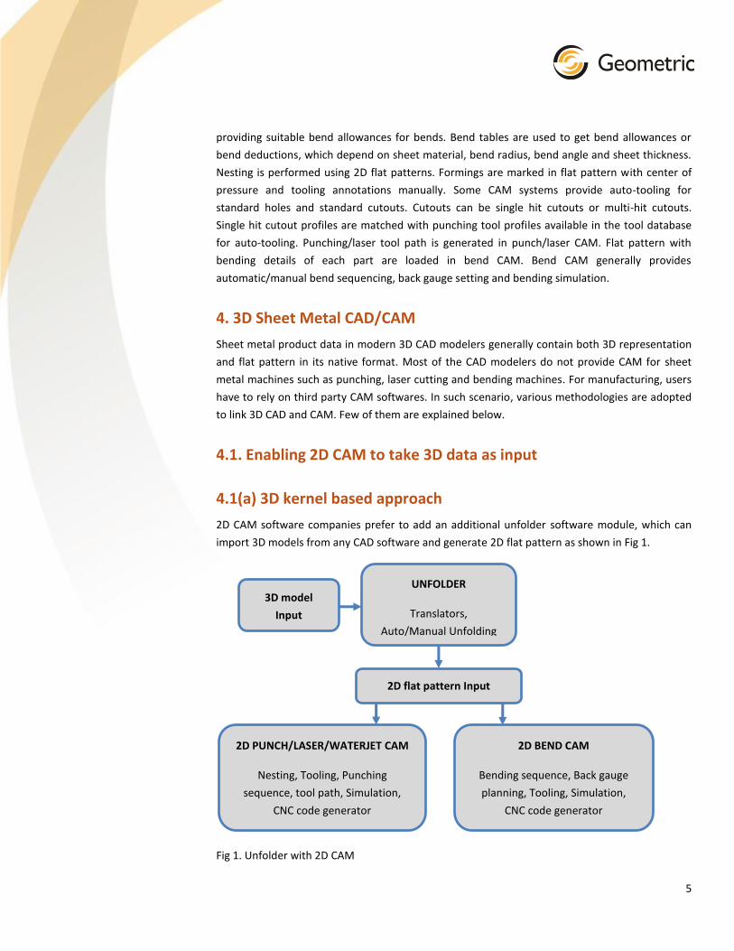
2D CAM software companies prefer to add an additional unfolder software module, which can
import 3D models from any CAD software and generate 2D flat pattern as shown in Fig 1.
Fig 1. Unfolder with 2D CAM
2D PUNCH/LASER/WATERJET CAM
Nesting, Tooling, Punching
sequence, tool path, Simulation,
CNC code generator
2D flat pattern Input
3D model
Input
2D BEND CAM
Bending sequence, Back gauge
planning, Tooling, Simulation,
CNC code generator
UNFOLDER
Translators,
Auto/Manual Unfolding

6
CAD data may come from any 3D modeler either in native file format or in standard file formats.
To open these models, translators are required. When CAD data is imported in any 3rd party
CAM software using translators, feature data and flat pattern data are lost and only the 3D
boundary representation data is extracted. This requires an unfolder module, which can generate
flat pattern from 3D data. To process 3D model into flat pattern, 3D kernels are generally used.
Translation errors complicate unfolding of such imported 3D models and require user interaction
or sometimes require complete recreation of flat pattern. Bend data is either extracted
automatically or entered manually. The major advantage of kernel based approach is to reuse
the 2D CAM without any change and the software becomes capable of handling both 2D as well
as 3D input. This type of software is suitable for manufacturing vendors who generally do not
design or modify the designs. Such vendors receive CAD data from multiple customers in various
formats and simply manufacture the products.
Companies who make design and manufacture in-house require design capabilities in CAD/CAM
softwares. To cater this need, some software companies have developed CAD software module
with only sheet metal modeling capabilities. These are lightweight CAD software modules that
can be used only to make designs for sheet metal products. Basic capabilities of such softwares
include 3D sheet metal modeling, unfolding native and imported geometry and 2D CAM as
shown in Fig 2.
Fig 2. Sheet metal CAD with 2D CAM
2D PUNCH/LASER/WATERJET CAM
Nesting, Tooling, Punching
sequence, tool path, Simulation,
CNC code generator
2D flat pattern Input
Imported 3D
model Input
2D BEND CAM
Bending sequence, Back gauge
planning, Tooling, Simulation,
CNC code generator
UNFOLDER
Translators,
Auto/Manual Unfolding
3D SHEET METAL
MODELER
Sheet metal modeling

7
Developing all the sheet metal modeling functionalities require huge development efforts and
investment. A major advantage of this approach is integrated CAD/CAM software in a single
application at a lesser end-user licensing cost. Further with modular design of the software, they
are also able to cater manufacturing vendors without modeling module at even a lesser licensing
cost.
4.1(b) 3D modeler based approach
CAM softwares sometimes utilize 3rd party CAD softwares and build add-ins to unfold and
generate output in required format for CAM. CAD and CAM softwares remain two independent
applications that are integrated by a common file format which is generated as output by CAD
and taken as input by CAM. The advantage of this type of approach is use of 3rd party CAD
modeler for modeling rather than developing all those functionalities and faster software
development cycle at a lesser investment. But the licensing cost of the software is generally
higher and the newly developed add-ins have to upgraded with every upgrade of CAD modeler.
4.2. Building a next generation 3D CAD / CAM
Working completely with 3D from start to end has its own advantages. For example, when
bending simulation is in 3D, it is easier to visualize the bending process and user experience is
much better. Similarly, for parts with punched forming features, 3D representation is better than
2D representation in flat patterns. 3D representation of forming features also facilitate auto-
tooling to a better extent. In 2D, parts have to be manually segregated as per thickness and
material before nesting whereas in 3D representation, segregation of parts in assemblies can be
automated. This kind of automation can save huge time involved in this activity and helps to
improve end-user productivity.
Most of the laser/waterjet machine manufacturers make 2.5 axis machines, 5 axis machines and
tube cutting machines. Multi-head machines with 2.5 axis for all heads or with 5 axis for few
heads is also common. Multi-head machines with both 2.5 and 5 axis are capable of cutting 2.5D
nested layouts as well as 5 axis profiles and they require a CAM software that is capable of
satisfying both 2.5 axis and 5 axis cutting. But, currently 2D CAM softwares for 2.5 axis cutting
and 3D CAM softwares with 5 axis milling module are generally used for 5 axis laser/waterjet
cutting. For tube cutting laser use of 2D/3D CAM is common. But all these softwares are mostly
independent applications and there is no integration between these. A CAD/CAM software that
is capable of 3D modeling and CAM for punch presses, 2.5 and 5 axis laser/waterjet machines,
tube cutting laser and bending machines will be most desirous by end users and machine-tool
manufacturers as shown in Fig 3.
The 3D CAD/CAM software should allow 3D modeling of both solid models, sheet metal models
and tubular models. It should facilitate easy migration from 2D CAD/CAM to 3D. The CAD module
should allow importing 2D flat patterns in DXF and other formats and convert them into 3D base
flanges, which can be accomplished by extruding the flat pattern.

8
Fig 3. Sheet metal 3D CAD with 3D CAM
Native 3D Sheet
metal model
3D Tube model 3D Sheet metal
free form model
3D MODELER
3D Sheet metal and solid modeling
Translators - Importing 3D models from other formats
Importing 2D flat patterns and converting into 3D
Imported 3D Sheet
metal model
UNFOLDER
Auto/Manual Unfolding
3D flat pattern Input
2.5 AXIS PUNCH/LASER CAM
Auto Tooling,
Punching sequence,
Tool path, 3D Simulation,
CNC code generator
NESTING
AUTOMATIC FEATURE RECOGNITION
3D BEND CAM
Bending sequence,
Back gauge planning,
Tooling, 3D Simulation,
CNC code generator
5 AXIS LASER CAM
Tool path,
3D Simulation,
CNC code generator
MULTIAXIS TUBE LASER CAM
Tool path,
3D Simulation,
CNC code generator

9
It should generate flat pattern for both native as well as imported sheet metal models and
provide an option for interactively unfolding parts with translation errors. User should be able to
give a single or a complete assembly as input for unfolding and nesting and the software should
automatically segregate parts as per thickness and material. Features should be automatically
extracted and auto-tooling for punching, part cutting sequence, tool path generation for
punching and 2.5 axis/5 axis/Tube laser cutting, auto-tooling for bending, bending sequence
generation, back gauge planning, CNC code generation, etc. should be performed. Simulation for
all these machines should in 3D.
5. Geometric provides building blocks for next generation 3D
CAD/CAM
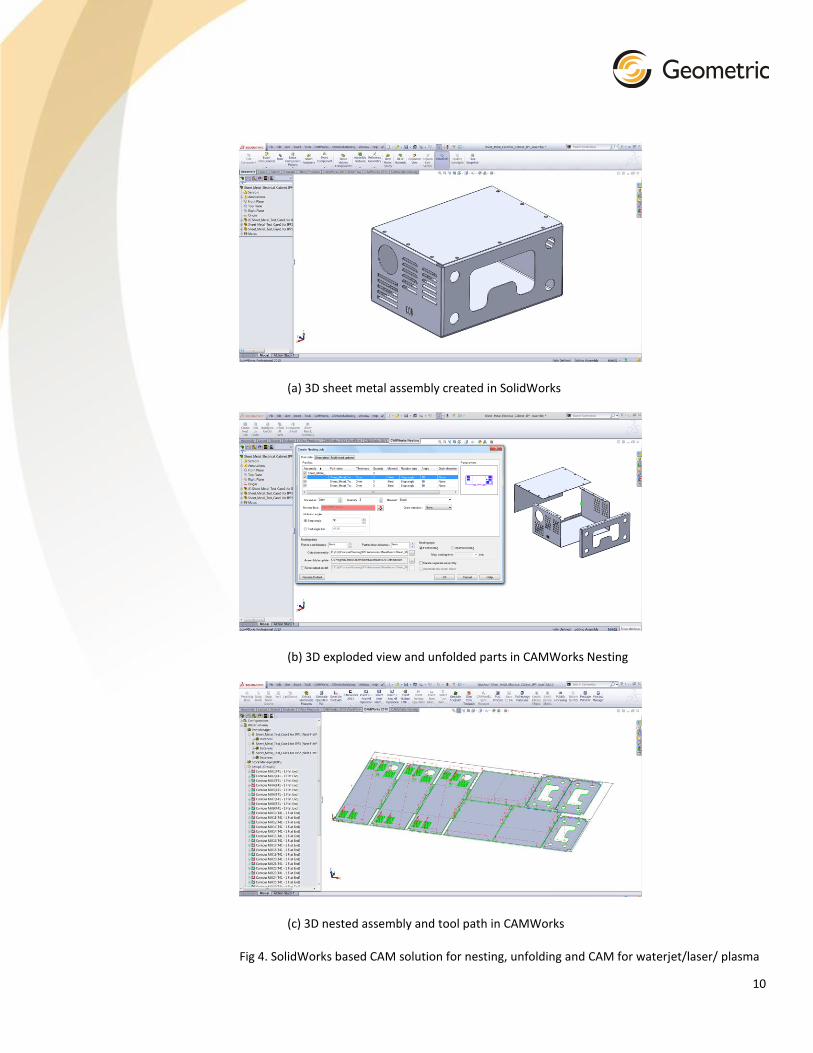
Geometric is a leader in implementing such next generation CAD/CAM solutions and has helped
multiple machine tool companies at different levels to implement such softwares. The approach
shown in Fig 3 is partially implemented by Geometric using our own products and technologies
on top of SolidWorks as shown in Fig 4. SolidWorks provides option to create add-ins so that
third party applications can be developed on top of it and can work as a single application.
SolidWorks provides a comprehensive 3D modeling software for Sheet metal, solid models and
pipe models. CAMWorks is a CAM software built as an add-in in SolidWorks for machining 2.5
axis, 3 axis, 5axis milling, turning, wire-edm, etc. CAMWorks Nesting is an add-in in SolidWorks
that is recently developed as an additional module for CAMWorks, which can also function as an
independent add-in in SolidWorks without CAMWorks. With CAMWorks Nesting and CAMWorks,
machining nested layouts using laser/waterjet/plasma/flame cutting are made possible by
suitably configuring the technology database of CAMWorks. Few screenshots of the system is
shown in Fig 4. DFMPro is also an add-in in SolidWorks that can automatically perform design for
manufacturability checks. Geometric's technology components like SMFR unfolder library and
Nestlib library are integrated in CAMWorks Nesting. Geometric's feature recognition library is
integrated in CAMWorks and DFMPro. Feature recognition library, Nestlib library, CAMWorks
Nesting, CAMWorks and DFMPro are available separately for licensing to OEMs.
10
(a) 3D sheet metal assembly created in SolidWorks
(b) 3D exploded view and unfolded parts in CAMWorks Nesting
(c) 3D nested assembly and tool path in CAMWorks
Fig 4. SolidWorks based CAM solution for nesting, unfolding and CAM for waterjet/laser/ plasma
11
6. Conclusion
Rising global competition and customer demands are driving the future course of sheet metal
CAD/CAM softwares. User-friendly softwares with a high level of automation that improves
productivity are the need of the day. Given the need for next generation CAD/CAM softwares for
sheet metal manufacturing, it is quite important to choose the best technologies to stay ahead.
With Geometric products and technologies, sheet metal machine tool manufacturers and
CAD/CAM ISVs can reap considerable benefits in terms of development cost and development
time.
About the Author
Dr. Kannan has over 20 years of R&D experience in CAD/CAM, engineering
software development, and manufacturing automation. He has a Ph.D. in
computer integrated manufacturing and process planning. He has published
multiple research papers in renowned international journals and conferences in
related areas. His area of expertise includes product management and R&D for
next generation CAD/CAM software products. He is currently a principal
consultant and responsible for research and development of various products like Feature
Recognition, Nestlib, CAMWorks Nesting and DFMPro,. He can be contacted at
Disclaimer
Author and Geometric respects the Intellectual Property Rights for every source it refers to. Care
has been taken to ensure that credits are mentioned. However, it is possible for some of the
things to be overlooked. If any such thing is observed, it is purely incidental and it is a sincere
request to bring it to the notice of the author.
References
1. http://www.camworks.com/
2. http://www.camworks.com/modules/camworksnesting/
3. http://feature.geometricglobal.com/
4. http://nestlib.geometricglobal.com/
5. http://dfmpro.geometricglobal.com/
6. www.solidworks.com
About Geometric
Geometric is a specialist in the domain of engineering solutions, services and technologies. Its
portfolio of Global Engineering services, Product Lifecycle Management (PLM) solutions,
Embedded System solutions, and Digital Technology solutions enables companies to formulate,

12
implement, and execute global engineering and manufacturing strategies aimed at achieving
greater efficiencies in the product realization lifecycle.
Listed on the Bombay and National stock exchanges in India, the company recorded consolidated
revenues of Rupees 10.20 billion (US Dollars 187.57 million) for the year ended March 2013. It
employs over 4600 people across 13 global delivery locations in the US, the UK, France, Germany,
Romania, India, and China. Geometric was assessed as CMMI 1.1 Level 5 for its software services
and is ISO 9001:2008 certified for engineering operations. The company’s operations are also ISO
27001:2005 certified.
The copyright/ trademarks of all products referenced herein are held by their respective companies.


