46
1/44 White Paper March 2006 RRC 04-06 Process Software solutions in radiocommunications
1/44
White Paper March 2006 RRC 04-06 Process
Software solutions in radiocommunications

2/44
TABLE OF CONTENTS
1 Importing Digital Requirements from ITU to ICS Manager 5
1.1 Importing from ITU notification files __________________________________ 5 1.2 Import from ITU Database___________________________________________ 8
2 Exporting ICS Manager records to ICS Telecom 12 3 Assignment and allotment planning 15
3.1 Assignment planning _____________________________________________ 15 3.2 Allotment planning _______________________________________________ 15 3.3 Allotments or assignments? _______________________________________ 15
4 Reference planning configuration and other planning parameters 15 4.1 Reference Planning Configurations (RPCs) ___________________________ 16 4.2 DVB-T __________________________________________________________ 16 4.3 T-DAB __________________________________________________________ 16 4.4 RPCs definition in ICS Telecom _____________________________________ 17
5 Creation of service area in ICS Telecom 18 5.1 Automatic creation of a service area for several requirements ___________ 19 5.1.1 The power sum method ___________________________________________ 20 5.1.2 The Rx antenna discrimination _____________________________________ 21 5.1.3 The rules________________________________________________________ 21 5.1.4 The ITU-R 370 / ITU-R 1546 / External models _________________________ 22 5.1.5 The options _____________________________________________________ 22 5.1.6 Location correction factor _________________________________________ 23 5.1.7 The propagation models___________________________________________ 25 5.2 Automatic creation of a service area for an SFN network________________ 27 5.3 Manual creation of a service area ___________________________________ 29 5.4 Delete a polygon _________________________________________________ 29 5.5 Creation of a station according to RRC04/06 __________________________ 30 5.6 Service areas of Reference Networks ________________________________ 33

3/44
6 Compatibility analyses 336.1 Definition of the calculation methods ________________________________ 336.2 Compatibility analysis in ICS Telecom _______________________________ 34 6.2.1 Select the rules __________________________________________________ 35 6.2.2 Set the protection ratios ___________________________________________ 36 6.2.3 Choice of the propagation model____________________________________ 36 6.2.4 Define the percentage of time ______________________________________ 37 6.2.5 The combined location correction factor _____________________________ 37 6.2.6 Compatibility on SFN networks _____________________________________ 37 6.2.7 Threshold definition for allotments __________________________________ 38 6.3 Compatibility analysis results ______________________________________ 39
7 Creation of ITU notification files 40 7.1 Directly from ICS Manager _________________________________________ 40 7.1.1 Creation of DS1, DT1, DS2, DT2 files_________________________________ 40 7.1.2 Creation of DA1 files ______________________________________________ 41 7.2 After a compatibility analysis_______________________________________ 43

4/44
INTRODUCTION The RRC rules give full flexibility to the Administrations in the formulation of the requirements to be provided to the RRC04-06. The administrations are allowed to choose between assignments and allotments and between single- and multiple-frequency networks. It is possible to use reference or individual planning configurations, as well as reference networks or individual transmitter characteristics. The choice depends on the specific needs of each country. Therefore, it necessitates a high responsibility for Administrations to make a reasonable choice for themselves and for the planning process as a whole. This document deals with the entire RRC04-06 process:
• Import of ITU notification files. • Choice of the planning configuration. • Creation of service areas (contours). • Compatibility analysis. • Creation of ITU notification files.
The whole process is described in details in this document by using ATDI software : ICS Telecom and ICS Manager.

5/44
1 Importing Digital Requirements from ITU to ICS Manager There are two possibilities in importing the requirements from ITU into ICS Manager:
• the ITU forms : DS1, DT1, DS2, DT2, DA1; • or the ITU database.
Both ways are equivalent and are very important in order to be able to perform the technical analysis with the neighboring countries.
1.1 Importing from ITU notification files In order to import the needs from a notification file go to the menu Broadcast VHF/UHF in ICS Manager and follow the link shown below:
The DT and DS forms could be in one file while the contours (DA1 forms) are in a separate file. To import DT and DS forms, use “From ITU Notification File to Coordination Table…”
6/44
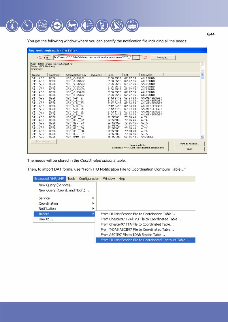
You get the following window where you can specify the notification file including all the needs:
The needs will be stored in the Coordinated stations table. Then, to import DA1 forms, use “From ITU Notification File to Coordination Contours Table…”

7/44
You get the following window where you can specify the notification file including all the contours:
The contours will be stored in the Coordinated contours table. Note that the t_action (MOD, ADD...) field is copied to the Last coordination request field in the Coordination tab.

8/44
1.2 Import from ITU Database In order to import the needs from the ITU table (for example: RRC06_29May2005), link first this table to ICS Manager (or it could be any other table with the same structure):
Then specify the table in the following window:
And after creating the connection, specify the tables from which you want to import the needs. In order to do so, right click on Queries in order to create new query :

9/44
You get the window where you can specify your tables ITU-R / BRIFIC FM/TV:
The Broadcast VHF/UHF notices and assignments table is including all allotments and assignments and the second one, RRC contours, is including all the contours. To import the BRIFIC allotments and assignments in the Coordinated stations table, go to the Broadcast VHF/UHF notices and assignments. You can apply a filter on any of its specific fields or you can select the records you want. Then right click on your selection and select Import BRIFIC record to Broadcast VHF/UHF coordinated assignments table…

10/44
The following window appears, then click on Yes.
The assignments and allotments have been imported in the Coordinated stations table. To import the BRIFIC contours in the Coordinated contours table, go to the RRC contours. You can apply a filter on any of its specific fields or you can select the records you want. Then right click on your selection and select Import RRC Contours to Coordination contours table…

11/44
The contours have been imported in the Coordinated contours table Now you can edit and check the new imported records in ICS Manager by creating new query: Queries / Assignments / Coordination and notification for broadcast VHF/UHF / …
Select Coordinated Contours table to display the contours. Select Coordinated Stations table to display assignments and allotments.

12/44
2 Exporting ICS Manager records to ICS Telecom Your requirements are now recorded in the ICS Manager's database. You can then easily export them into ICS Telecom to carry out the technical analysis. First of all start ICS Manager from ICS Telecom using Tools / ICS Manager
Then, open your workspace and select the table on which you want to work. In order to export the records to ICS Telecom, select the required records, right click on any of them and select: Export / Export to ICS Telecom map…
When the export on ICS Telecom map is done, you will get:
• For an assignment : the assignment (station) with all its technical parameters and the contour associated;
Note that the Reference planning configuration (RPC1 - RPC5) is exported as Type='1' for RPC1, Type='2' for RPC2, and so on… in the Type field of the Tx/Rx parameters box of ICS Telecom.
• For an allotment: one station and the contours associated to this allotment, with its specific
frequency. Note that in order to get the contours as polygons on the map of ICS Telecom, you should have imported the contours from the RRC contours ITU table into the Coordinated contours table of ICS Manager.

13/44
• For contours: when exporting allotments or assignment to ICS Telecom, ICS Manager exports the contour(s) associated in the following order of priorities :
1) The test points stored in the assignment record; 2) The test points stored in the related allotment record; 3) The list of contour numbers stored in the related allotment record (allotment area). If there are several contours, ICS Manager will choose the one in which the assignment is inside.
It is also possible to export contours alone on ICS Telecom map as vectors. In order to do so, select all the contour records in the Coordinated contours table, right click on it and select Export to ICS Telecom .VEC file…
Specify a threshold value to the contour. This value depends on the service to consider and will be used in the compatibility analysis.

14/44
Then the .VEC file can be directly loaded in ICS Telecom. Select Files / Load / Load vector file (.VEC)
After having imported all requirements on the map, different methods are offered in ICS telecom for the analysis and more specifically compatibility analysis based on test points. These methods are described in section 6 of this document.

15/44
3 Assignment and allotment planning One important element of the planning process is the treatment of assignments and allotments. Assignments and allotments are fundamental tools to create a frequency plan. T-DAB planning is based on allotment planning, whereas DVB-T planning is based on either allotment or assignment planning or a combination of both. In allotment planning, no current location of the transmitter site is known, nor the specific transmission characteristics to be used.
3.1 Assignment planning In assignment planning, a specific channel is assigned to an individual transmitter site with predefined location and transmission characteristics (for example, radiated power, antenna height, etc.). After completion of the assignment planning, the locations and characteristics of all transmitters are known and the transmitters can be brought into service without further coordination.
3.2 Allotment planning In allotment planning, a specific channel is “given” to an administration to provide coverage over a defined area within its service area, called the allotment area. Transmitter location and associated characteristics are unknown at this stage and has to be defined when converting the allotment into one or more assignments.
3.3 Allotments or assignments? The following applies to both DVB-T and T-DAB networks :
• An allotment requirement is more appropriate : o when an SFN is required; o or when the characteristics of the transmitters to be used to cover an area are not known yet; o or when the transmitter characteristics might be amended : before, during or after
implementation.
• An assignment requirement is more appropriate : o when a network is to be implemented as an MFN; o or when all the relevant transmitter characteristics are already known.
• Assignment requirements may be also associated with an allotment requirement if, for example
o the administration concerned has already “pre-co-coordinated” those assignments with other administrations, and then concluded an agreement;
o or if an administration or a network operator planning for an SFN already knows the major transmitter sites, but not the whole network structure yet.
4 Reference planning configuration and other planning parameters If the administration already knows the system variant (and other planning information such as the reception type) that will be used for a given requirement, it can provide this as part of the requirement specification. If the relevant decisions have not been made yet², the administration can specify a Reference Planning Configuration (RPC).

16/44
For T-DAB networks, it is not possible to specify anything else than a RPC.
4.1 Reference Planning Configurations (RPCs) To simplify the planning process it is useful to reduce the number of possible planning configurations to just a few. These representative networks are called Reference Planning Configurations (RPCs). They are not identical to “real” network implementations, but they are helpful for the compatibility analysis. Three RPCs are defined by the RRC for DVB-T and two for T-DAB. For DVB-T, it is also possible under RRC rules to specify a system variant and reception conditions. DVB-H could be specified in this way. For T-DAB, one of the two defined RPCs must be used.
4.2 DVB-T In order to simplify the planning process (several thousands of different DVB-T planning configurations are available), three reference planning configurations (RPCs) are proposed, each representing a typical planning configuration:
• one for fixed reception (RPC 1); • one for portable outdoor or mobile reception (RPC 2); and • one for portable indoor reception (RPC 3).
Figure 1: Reference planning configuration for DVB-T
The Reference minimum field strength (Emed)ref is defined at 10 m above ground level, for 50% of locations and 50% of the time. The height loss values are taken from ITU-R P.1546-2 recommendation. The system variant for a difficult reception mode, e.g. portable indoor, has to be more rugged than for a less difficult reception mode, e.g. fixed roof-level. Therefore, the reference C/N value decreases with increasing demand on the reception mode.
4.3 T-DAB Reference Networks for mobile T-DAB reception (RPC 4) and portable indoor T-DAB reception (RPC 5) have been developed, the only difference between them being the 9 dB higher RP needed for RPC 5.
17/44
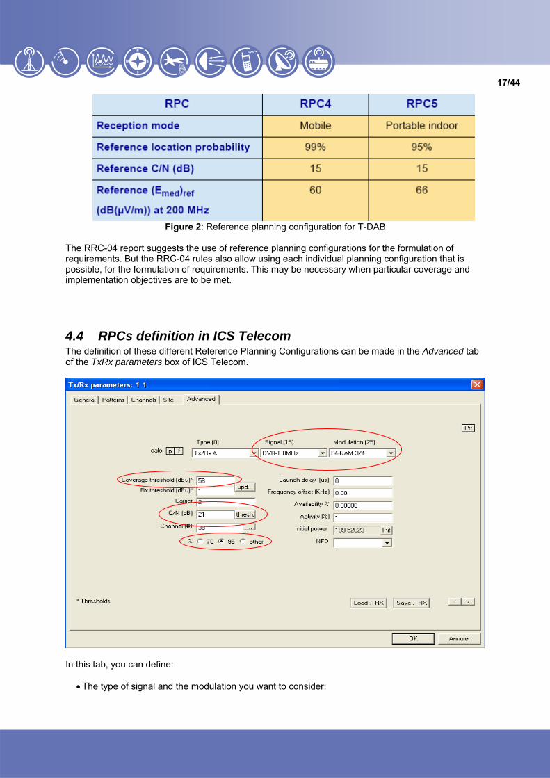
Figure 2: Reference planning configuration for T-DAB
The RRC-04 report suggests the use of reference planning configurations for the formulation of requirements. But the RRC-04 rules also allow using each individual planning configuration that is possible, for the formulation of requirements. This may be necessary when particular coverage and implementation objectives are to be met.
4.4 RPCs definition in ICS Telecom The definition of these different Reference Planning Configurations can be made in the Advanced tab of the TxRx parameters box of ICS Telecom.
In this tab, you can define:
• The type of signal and the modulation you want to consider:

18/44
• The reference location probability: 70%, 95% or an other location probability
• The reference C/N (dB):
By clicking on thresh. button, the coverage threshold is automatically updated.
This coverage threshold corresponds to the reference minimum field strength (Emed)ref and depends on the frequency, the reference location probability value, and on the reference C/N value set. The location correction factor is taken into account as defined in the annex A.3.5.1 of the RRC04.
5 Creation of service area in ICS Telecom In order to be able to deal with number of requirements which may be specified as assignments, allotments or as a mixture of these two, it is necessary to assume that the area to be covered by any of them is specified in the same way. The following assumes that this is done by means of a series of geographic locations, referred to as test points, located at the boundary of that area. As defined in the RRC04, the contour zone is the part of the coverage area in which the administration has required the agreed protection conditions to be provided.

19/44
The test point location at which the wanted field strength is to be determined will be defined as part of the planning process. These test point locations may be calculated or may be defined by the concerned administration.
In ICS Telecom, service areas will be represented by polygons. Each polygon can be associated to a station or can be defined as a vector polygon. The user can create them manually or automatically, for one or more requirements. ICS Telecom considers an allotment as a group of contours defined by a set of test points, each contour constituting a polygon.
5.1 Automatic creation of a service area for several requirements ICS Telecom can generate a polygon for several requirements at the same time. No predefined coverage calculation is required, a point to point calculation is made.
Options / Report / ITU coordination / UFS polygon calculation…
This window is divided in 5 parts:

20/44
5.1.1 The power sum method
In this part you can select the power sum method you want to consider to calculate the UFS polygons. Here is a description of each summation method: - Sum method: the UFS is defined by the following formula, where NFS(i) is the NFS due to the i-th
interferer expressed in dBµV/m:
UFS = 10 x Log10(Σi10NFS(i)/10) This summation method is also the one defined in the § 5.3.1.3.6 of the RRC04 for the calculation of the unwanted signal summation. This is the method to be used for polygons generation with interferers. - Chester method: this summation method corresponds to the specifications of section 6 of the
Chester agreement, i.e.:
UFS = 10 x Log10(10Threshold/10+Σi10(NFS(i)+C)/10) C is the propagation correction factor. If the wanted signal is analogue, the value of C is equal to 0 dB. If the wanted signal is digital, the value of C depends on the location factor and on the C/N value. - Bonn method: this is the summation method specified in the Bonn agreement. - SMM method: the SMM method refers to the Simplified Multiplication Method specified in the
Geneva 84 agreement. This method is fully described in the CCIR-945 report (1982). Note that the "sigma" value is equal to 8.3dB in VHF and to 9.5dB in UHF. The percentage to be set by the user is the percentage of location. If a statistical propagation model (ITU-R 370 or ITU-R 1546-2), this parameter should be coherent with the location probability specified in the propagation model and in the parameters of the digital transmitters. - k-LNM method: this method is the one described in the Annex 5.3.1 of the RRC04. One uses a
value of k of 0.6, which should make it possible to obtain a precision about a few dB for location probabilities between 70% and 99%.
Note: the k-LNM method is normally used for the calculation of the wanted signal summation for SFN’s.
21/44
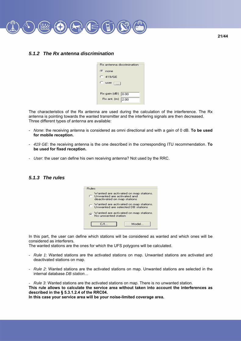
5.1.2 The Rx antenna discrimination
The characteristics of the Rx antenna are used during the calculation of the interference. The Rx antenna is pointing towards the wanted transmitter and the interfering signals are then decreased. Three different types of antenna are available: - None: the receiving antenna is considered as omni directional and with a gain of 0 dB. To be used
for mobile reception. - 419 GE: the receiving antenna is the one described in the corresponding ITU recommendation. To
be used for fixed reception. - User: the user can define his own receiving antenna? Not used by the RRC.
5.1.3 The rules
In this part, the user can define which stations will be considered as wanted and which ones will be considered as interferers. The wanted stations are the ones for which the UFS polygons will be calculated. - Rule 1: Wanted stations are the activated stations on map. Unwanted stations are activated and
deactivated stations on map. - Rule 2: Wanted stations are the activated stations on map. Unwanted stations are selected in the
internal database DB station… - Rule 3: Wanted stations are the activated stations on map. There is no unwanted station. This rule allows to calculate the service area without taken into account the interferences as described in the § 5.3.1.2.4 of the RRC04. In this case your service area will be your noise-limited coverage area.

22/44
When interference is taken into account to define the UFS service area, the C/I protection must be defined in the C/I parameters by the use of ITU tables.
5.1.4 The ITU-R 370 / ITU-R 1546 / External models
This is to take tropo and steady interference into account. The worst case between tropo and steady interference is taken into account.
Specify here the percentage of time considered for the wanted and the unwanted signal. The percentage of location is defined in the propagation model must always be equal to 50%.
5.1.5 The options
If coverage is attached to one or several stations, ICS Telecom will create the polygon based on these coverages. To ignore the existing coverage, select in this part the Do not use Tx coverage (if present) option. The polygon will be the calculated in point to point mode. The polygons can also be limited to the country border by using the Border limited polygon option. In order to use this option, a .COD file (defining the borders) must be previously loaded.

23/44
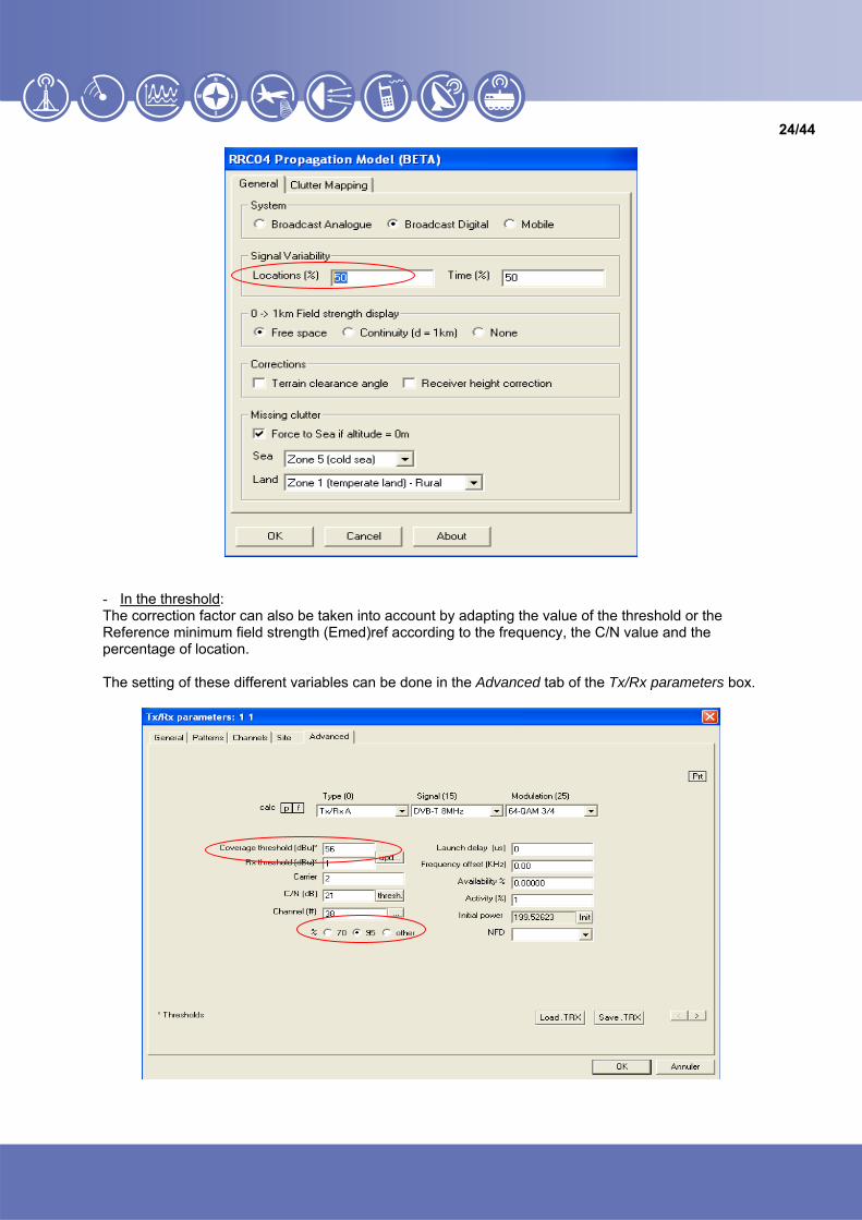
5.1.6 Location correction factor The location correction factor is the ratio, expressed in dB, of the field strength exceeded for a given percentage of the receiving locations to the field strength exceeded for 50% of the receiving locations. Two ways are offered to take into account this correction factor in ICS Telecom: - In the propagation model; - In the threshold. In both cases the correction factor implemented is the one defined in the annex A.3.5.1 of the RRC04. - In the propagation model: The correction factor is taken into account when you define a percentage of location different from 50%. The method presented here is assuming that the correction factor is included in the threshold. So, set the location probability to 50%.
24/44
- In the threshold: The correction factor can also be taken into account by adapting the value of the threshold or the Reference minimum field strength (Emed)ref according to the frequency, the C/N value and the percentage of location. The setting of these different variables can be done in the Advanced tab of the Tx/Rx parameters box.
25/44
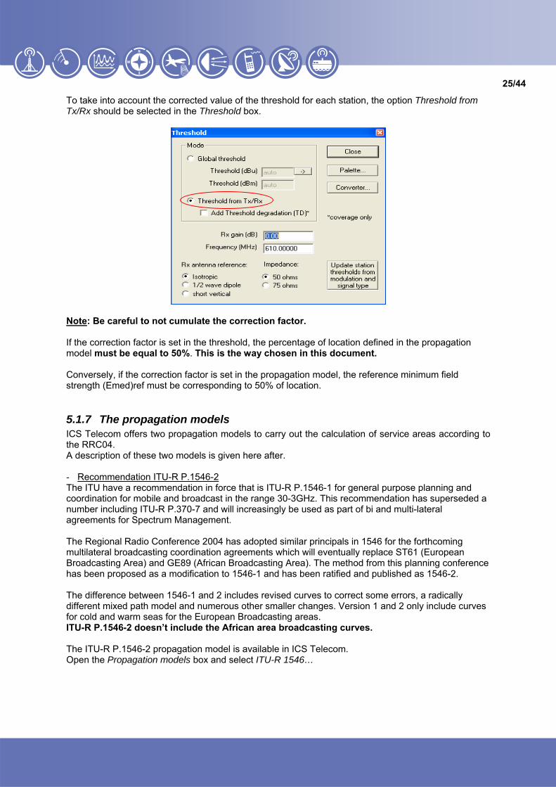
To take into account the corrected value of the threshold for each station, the option Threshold from Tx/Rx should be selected in the Threshold box.
Note: Be careful to not cumulate the correction factor. If the correction factor is set in the threshold, the percentage of location defined in the propagation model must be equal to 50%. This is the way chosen in this document. Conversely, if the correction factor is set in the propagation model, the reference minimum field strength (Emed)ref must be corresponding to 50% of location.
5.1.7 The propagation models ICS Telecom offers two propagation models to carry out the calculation of service areas according to the RRC04. A description of these two models is given here after. - Recommendation ITU-R P.1546-2 The ITU have a recommendation in force that is ITU-R P.1546-1 for general purpose planning and coordination for mobile and broadcast in the range 30-3GHz. This recommendation has superseded a number including ITU-R P.370-7 and will increasingly be used as part of bi and multi-lateral agreements for Spectrum Management. The Regional Radio Conference 2004 has adopted similar principals in 1546 for the forthcoming multilateral broadcasting coordination agreements which will eventually replace ST61 (European Broadcasting Area) and GE89 (African Broadcasting Area). The method from this planning conference has been proposed as a modification to 1546-1 and has been ratified and published as 1546-2. The difference between 1546-1 and 2 includes revised curves to correct some errors, a radically different mixed path model and numerous other smaller changes. Version 1 and 2 only include curves for cold and warm seas for the European Broadcasting areas. ITU-R P.1546-2 doesn’t include the African area broadcasting curves. The ITU-R P.1546-2 propagation model is available in ICS Telecom. Open the Propagation models box and select ITU-R 1546…

26/44
If you click on the button RC04 (EBA), the default values for RRC04 are automatically updated. Propagation curves from Recommendation ITU-R P.1546-2 are corrected for various factors including: location and time variability, transmitting and receiving antenna heights, clutter environments, atmospheric refractive index gradient, frequency band and propagation path type (land, cold sea, warm sea & mixed). In addition to this, the method includes corrections for ground obstructions derived from a digital elevation model (DEM) along the path profile. - RRC04.dll: RRC04 is not the same as ITU-R P1546 and does not give the same results however similar they may appear. The fact that RRC04 is based upon 1546 does not mean they agrees because the model in RRC04 is a subtle variation to 1546-1 and has big changes to the mixed path model amongst other things. Thus the difference between 1546-2 and RRC04 is simply that RRC04 includes the propagation curves for different regions in Africa and the Middle East. This .dll is not provided with ICS Telecom, it must be ordered separately (around 1500€ VAT Excluded). To select this propagation model in ICS Telecom, open the Propagation models box and select Usermod.dll.
Then load the RRC04.dll.

27/44
When all the parameters are defined, click on Start to launch the batch calculation.
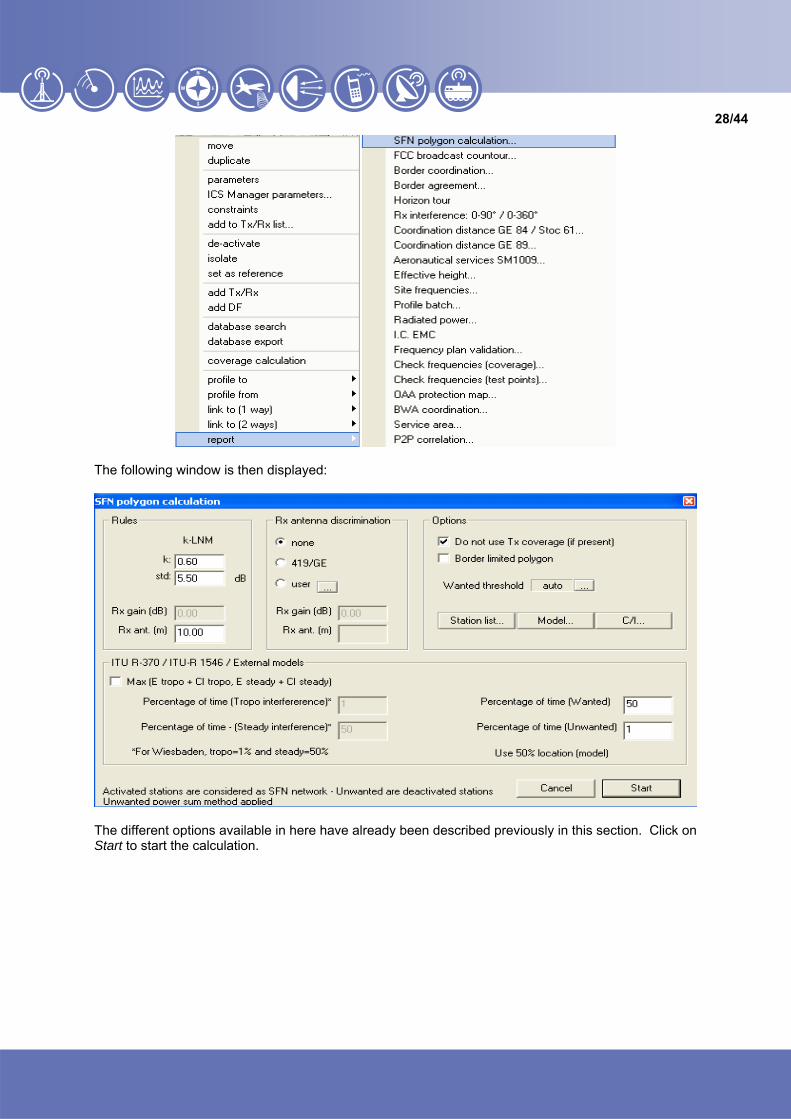
5.2 Automatic creation of a service area for an SFN network In case of SFN, the test points limiting the service area are calculated according to the k-LNM method. To create such a service area, first select a station which will be considered as the reference station of the SFN network. All others activated stations on the map will be considered as part of the SFN network. All deactivated stations on the map will be considered as unwanted (potential interferers). The summation of the unwanted signals is made according to the Power Sum method. Select a station and then select Report / SFN polygon calculation…
28/44
The following window is then displayed:
The different options available in here have already been described previously in this section. Click on Start to start the calculation.

29/44
5.3 Manual creation of a service area In ICS Telecom it is also possible to manually create a service area by drawing a polygon. Select the polygon tool and left click on the map.
Then select draw mask.
Then, save this polygon as a vector polygon Add polygon to vector file… and define the properties of the vector.
You can associate a threshold value to the polygon. This value will be used by the compatibility analysis.
5.4 Delete a polygon To delete a polygon attached to a station, go to the Site tab of the Tx/Rx parameters box and then click on delete polygon :

30/44
5.5 Creation of a station according to RRC04/06 If a service area (contour) has been created or imported without any information except the threshold, the compatibility analysis needs to associate a station to this service area in order to carry out the calculations. In the parameters window of the polygon vector, define the threshold value which is relative to the type of reception inside this polygon. This threshold value will be taken into account as the minimum value that should be protected on each test points of the allotment contour.

31/44
Then use Add station according to RRC04/06…
This function adds a transmitting station on the highest point inside the polygon and calculates the required transmitted power and horizontal diagram in order to be received with the specified threshold on each vertex of the polygon. Specify the frequency, the transmitter antenna height and the receiver antenna height :
Location of the virtual station
In the given example the power radiated will be equal to 158.49 W. The station will be created on the highest point inside the Allotment (polygon). The technical parameters of the virtual station will be as follows:

32/44
And for the Antenna pattern:
The station creation will be based on the propagation model that is specified in the propagation models window, so in case of compatibility analysis the user should be sure that the ITU-R P.1546-2 model is checked along with the correct parameters.

33/44
5.6 Service areas of Reference Networks Section 5.5 should avoid the use of reference networks. If required, please refer to the "RRC04-06 - Reference networks" document.
6 Compatibility analyses One fundamental step in establishing a frequency plan is the compatibility analysis. The outgoing interfering field strength of a transmitter or transmitter network will be of substantial interest because it can impair the functionality of other co-channel service areas. The interference potential is defined by power, effective antenna height, antenna pattern and the transmitter locations. If the real network implementation is not known yet, the interference potential of a station created according to RRC04/06 (see section 5.5) may be used as a representative in the compatibility analysis. The compatibility analysis is not limited to technical calculations. There is an opportunity for administrations to declare pairs of requirements compatible that might appear, on the technical bases used, to be not compatible. Likewise, requirements which appear to be compatible can be declared incompatible...
6.1 Definition of the calculation methods In order to identify requirements which are not compatible, two sets of calculations are required. The first set identifies requirements which have a service overlap, and the second set identifies requirements which would produce excessive interference if operating on the same channel. To identify requirements which overlap, it is necessary to examine each of the test points for one requirement to determine if it lies inside the area of a second requirement. Because there can be anomalies in the cases where there are large separation distances between adjacent test points, it is also necessary to repeat the examination to determine if any of the test points of the second requirement lies inside the area of the first requirement. To identify requirements which are not compatible because of potential interference, it is necessary to consider three cases:
• where both of the requirements are specified as assignments; • where one of requirement is specified as an assignment and the other as an allotment; • where both requirements are specified as allotments. In the three cases above, the assessment of the protection margin is made separately for every test
point that defines the area to be served.
The wanted field strength is:
• In the case of an assignment, the reference field strength for 50% of the time and 50% of locations or the calculation result made for 50% of the time and 50% of locations.
• In the case of an allotment, the reference field strength for 50% of the time and 50% of locations.
The nuisance field strength is calculated for 50% of locations and for 1% of the time (thus providing protection against interference for 99% of the time) except where a value greater than 1% is agreed between the concerned administrations.

34/44
The wanted field strength and the reference field strength are dependent on the service conditions. These service conditions include:
• Reception mode: fixed, portable or mobile; • Type of service: television or sound radio; • System variant: 64-QAM, 16-QAM or QPSK together with the code rate to be used; • Reference planning configuration; • Target percentage of locations to be achieved.
The calculations described above are needed for the case of the first requirement considered as the source of potential interference to the second requirement, and for the case of the second requirement considered as the source of potential interference to the first requirement. If the protection margin is negative at any test point of either requirement, the two requirements are considered as not compatible. The protection margin is calculated as:
wanted field strength - nuisance field strength - combined location correction factor In this formula, the wanted and nuisance field strengths are referring to 50% of location probability. The purpose of the combined location correction factor is to convert the protection margin to the percentage of location probability needed for the wanted service.
6.2 Compatibility analysis in ICS Telecom To carry out a compatibility analysis in ICS Telecom, use the following function: Options / Report / ITU coordination / Compatibility report…
35/44
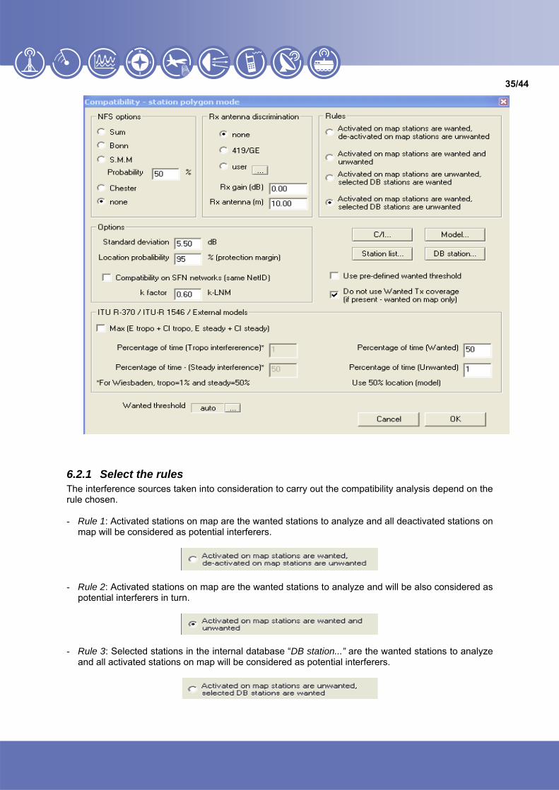
6.2.1 Select the rules The interference sources taken into consideration to carry out the compatibility analysis depend on the rule chosen. - Rule 1: Activated stations on map are the wanted stations to analyze and all deactivated stations on
map will be considered as potential interferers.
- Rule 2: Activated stations on map are the wanted stations to analyze and will be also considered as
potential interferers in turn.
- Rule 3: Selected stations in the internal database “DB station...” are the wanted stations to analyze
and all activated stations on map will be considered as potential interferers.

36/44
- Rule 4: Activated stations on map are the wanted stations to analyze and selected stations in the internal database “DB station...” will be considered as potential interferers.
6.2.2 Set the protection ratios From the protection ratio values for digital broadcasting systems it is apparent that only co-channel or overlapping channel interference need be taken into account and that adjacent channel and image channel interference may be neglected.
• For DVB-T (against DVB-T, T-DAB and analogue television, and conversely), the protection ratios given in Recommendation ITU-R BT.1368 should be used.
• For T-DAB against T-DAB, a value of 15 dB should be used. • For wanted T-DAB against DVB-T or analogue television, the protection ratios given in
Recommendation ITU-R BS.1660 should be used. • For wanted analogue television vis-à-vis T-DAB, the protection ratios given in Recommendation
ITU-R BT.655 should be used. To define the protection ratios given by the different Recommendation you must used the following option C/I tables, in the C/I box:
6.2.3 Choice of the propagation model ICS Telecom offers two propagation models to carry out the compatibility analysis according to the RRC04. A description of these two models has already been given in section 4.2.7. Independently of the choice of the propagation model, the percentage of location must always be equal to 50% in the propagation model window during the compatibility analysis.
37/44
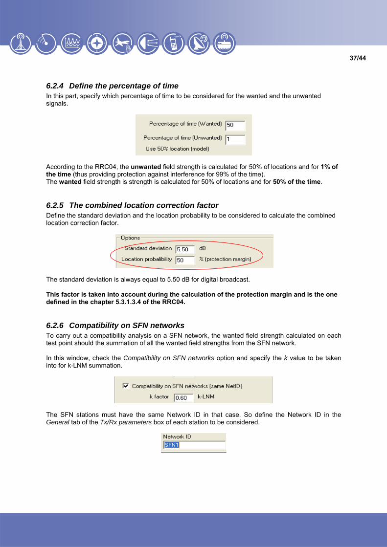
6.2.4 Define the percentage of time In this part, specify which percentage of time to be considered for the wanted and the unwanted signals.
According to the RRC04, the unwanted field strength is calculated for 50% of locations and for 1% of the time (thus providing protection against interference for 99% of the time). The wanted field strength is strength is calculated for 50% of locations and for 50% of the time.
6.2.5 The combined location correction factor Define the standard deviation and the location probability to be considered to calculate the combined location correction factor.
The standard deviation is always equal to 5.50 dB for digital broadcast. This factor is taken into account during the calculation of the protection margin and is the one defined in the chapter 5.3.1.3.4 of the RRC04.
6.2.6 Compatibility on SFN networks To carry out a compatibility analysis on a SFN network, the wanted field strength calculated on each test point should the summation of all the wanted field strengths from the SFN network. In this window, check the Compatibility on SFN networks option and specify the k value to be taken into for k-LNM summation.
The SFN stations must have the same Network ID in that case. So define the Network ID in the General tab of the Tx/Rx parameters box of each station to be considered.

38/44
6.2.7 Threshold definition for allotments In the case you want to analyse the compatibility on allotments you must be able to define the reference thresholds of the RPC associated to yours allotments. This value of reference threshold will be the value of the FS wanted on each test points of the allotment.
To do so, select the option Use pre-defined wanted threshold.
Select the option Threshold from Tx/Rx.
And define the specific threshold you want to take into account in the Advanced tab of the Tx/Rx parameters box of the station which is associated to your allotment.
Reference threshold for RPC2 at 650 MHz
As soon as every calculation parameters are defined, click on OK to carry out the compatibility analysis.

39/44
6.3 Compatibility analysis results At the end of the compatibility analysis, a window is displayed and shows if stations are compatible or not (OK or NOK).
If the requirements are not compatible one with another, click on List to have the details of the compatibility analysis on each vertex. In this sheet, the protection margin calculated on each interfered vertex is displayed

40/44
7 Creation of ITU notification files
7.1 Directly from ICS Manager To create an ITU notification file in ICS Manager, first select the appropriate table :
• To create DS1, DT1, DS2 and DT2 files, use in the coordinated stations table. • To create DA1 files, use the coordinated contours table.
7.1.1 Creation of DS1, DT1, DS2, DT2 files In the coordinated stations table, select the assignments or allotments which will compose the ITU notification file and right click on it. Select Export / Export to ITU file (not for notification)…
In the following window fill the fields which will compose the head of the ITU file and click on OK.
Then enter the ITU file name and click on Open:

41/44
The ITU file has been created.
To edit it you can open the .txt file you have just created.
7.1.2 Creation of DA1 files In the coordinated contours table, select the contours to be notified and right click on them. Select Export RRC Contours to ITU Notification file (DA1)…
42/44
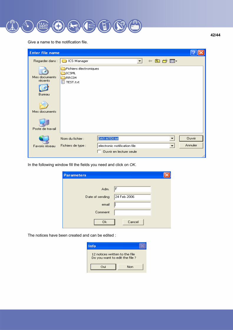
Give a name to the notification file.
In the following window fill the fields you need and click on OK.
The notices have been created and can be edited :

43/44
7.2 After a compatibility analysis After having carried out all the analysis and updates required in ICS Telecom, it is time to export all the needs back to ICS Manager and then generate the needs in the ITU format. To export the modifications made in ICS Telecom to ICS Manager, use Files / Export / Export to ICS Manager…
In the following window, select Save station changes to ICS Manager.

44/44
A report is automatically created summarizing all the modifications made on the assignment(s) or allotment(s). In the top of this window the unique identifier of the requirement is displayed. It can be updated as well as the old values and the new imported values.
The changes that are taken into account are the following:
• For an assignment: o The required channel; o The polarization; o The azimuth; o The radiated power; o The antenna patterns (H / V); o The effective heights; o The coordinates (latitude / longitude); o The test points of the new contour.
• For an allotment:
o The required channels; o The polarization; o The test points of the new contour.

45/44
If you agree with the changes, click on Apply checked changes and continue and click on Yes in the following window.
The changes have been stored in ICS Manager.

46/44
To create the modified notification files, follow the process define in section 7.1.
ATDI UA partnership with LISerbitskogo str. 1 02068 Kiev Ukraine Tel +380 44 564 33 68 e-mail : v [email protected]:// www.lissoft.com.ua
ATDI South Pacific PTY Ltd79 Macarthur Street - Ultimo NSW 2007 - Australia Tel. +61 (0)2 9213 2200 Fax +61 (0)2 9213 2299 e-mail : [email protected]://www.atdi.com
ATDI OOO Sadovnicheskaya st. 72 bld 1 115035 Moscow - Russian Federation Tel. +7 095 252 96 10 Fax +7 501 408 50 74 e-mail : [email protected]://www.atdi.ru
ATDI EST Bd. Aviatorilor, 59 Bucharest Romania Tel +40 21 222 42 10 Fax +40 21 222 42 13 e-mail : [email protected]://www.atdi.ro
ATDI SAL812 Tabaris, Avenue Charles Malek Achrafieh, Beirut - Lebanon Tel. +961 1 330 331 Fax +961 1 216 206 e-mail : [email protected]://www.atdi.com
ATDI Ltd. Kingsland Court - Three Bridges Road Crawley - West Sussex - RH10 1HL - UK Tel. +44 (0)1293 522052 Fax +44 (0)1293 522521 e-mail : [email protected]://www.atdi.co.uk
ATDI Ibérica c/Manuel González Longoria,8 28010 Madrid - Spain Tel. +34 91 44 67 252 Fax +34 91 44 50 383 e-mail : [email protected]://www.atdi.es
ATDI SA 8, rue de l’Arcade 75008 Paris - France Tel. +33 (0) 53 30 89 40 Fax +33 (0)1 53 30 89 49 e-mail : [email protected]://www.atdi.com
ATDI Inc.2, Pidgeon Hill Drive, Suite 560 Sterling - VA 20165 - USA Tel. +1 703 848 4750 Fax +1 703 848 4752 e-mail : [email protected]://www.atdi-us.com
Software solutions in radiocommunications


