16
White Paper on the use of DVB-S2X for DTH applications, DSNG & Professional Services, Broadband Interactive Services and VL-SNR applications DVB Document A172 March 2015

!!!!
!!!!!!!!!!!
White Paper on the use of DVB-S2X for DTH applications, DSNG & Professional Services,
Broadband Interactive Services and VL-SNR applications
DVB Document A172
March 2015

White Paper on the use of DSNG & Professional
and VL
Scope
In October 2012 the Commercial Module (CM) requested improvements to the DVBperformance in the core markets (Direct to Home, contribution, VSATapplications of the standard to cover either emergiapplications. In order to allow for a rapid market launch the proposed extensions were to be an evolution of the DVBstandard rather than a fundamental change to the architecture.This document describes the advantages of the DVBprovide high level guidance to broadcasters and operators considering adoption of this system.It assumes a reasonable familiarity with the original DVBinterests of clarity and brevity. The DVB-S2 (EN 302 307) document is now divided in two partsspecification and Part 2 (EN 302 307compatible with the DVB-S2 specifications as the Part are not forward compatible with the DVBtransmissions using the new DVB-S2X featuresDVB-S2 transmissions.
Summary of main technical improvements
DVB-S2X extends the range of operation of DVBextend functionality in noise compromised environments very-high SNR operation range (VH-SNRlinks. DVB-S2X enhances the physical layer signalling and coding (MODCOD) schemes), enabling more S2X allows the use of reduced roll-off factors transmissions in the “linear channel” (for DVB-S2X also improves some features of the satellite transmission at • the ability to configure the scrambling sequence
broadcast (DTH) is now made normative co-channel interference in multi-satellite
• the changes in modulation, which optional), are now possible on a framethe transmission efficiency versus the transmission robustness
• channel bonding is permitted whichtransponders, thus enhancing the performance of the statistical multiplexing of services
• the higher level protocols (i.e. GSE, GSEsystems
• the “all-IP streaming” capability has been introduced. In summary, these technical enhancements offer the
• for DTH applications each of the and flexibility, but in combination theysystem, specifically they offer a road map to new generation services such as UHDTV
• for VSAT applications, the DVBfor future broadband interactive networksas multi-format transmissions.
1 VL-SNR frames may be inserted in DVB-S2 and
taken when using these frames in DVB-S2 transmissions
TM-S ad-hoc group the use of DVB-S2X for DTH application
rofessional Services, Broadband Interactive and VL-SNR applications
In October 2012 the Commercial Module (CM) requested improvements to the DVBin the core markets (Direct to Home, contribution, VSAT and DSNG) and to increase the range of
to cover either emerging markets such as mobile (air, sea . In order to allow for a rapid market launch the proposed extensions were to be an evolution of the DVB
standard rather than a fundamental change to the architecture. nt describes the advantages of the DVB-S2 extensions (herein referred to as DVB
provide high level guidance to broadcasters and operators considering adoption of this system.assumes a reasonable familiarity with the original DVB-S2 standard and has been intentionally kept simple in the
S2 (EN 302 307) document is now divided in two parts. Part 1 (EN 302 307-1) is the original (EN 302 307-2) defines the DVB-S2X extensions. Any DVB-S2X receiver is backwards S2 specifications as the Part 1 implementation is mandatory, but legacy
DVB-S2X extensions. Accordingly, the legacy DVB-S2 receivers wiS2X features, while the new DVB-S2X receivers will decode both
technical improvements
range of operation of DVB-S2 with a very-low SNR operation range (extend functionality in noise compromised environments and low power applications such as VSAT networks
SNR), which will improve throughput on high capacity trunk and contribu
physical layer signalling to provide a finer granularity of operative points), enabling more flexibility with regard to optimising channel usage
off factors in order to decrease the occupied bandwidth(for instance in the case of multi-carrier per transponder in
S2X also improves some features of the satellite transmission at the system level: scrambling sequence, which was normative in DVB-S2 for all applications except
made normative for DTH as well. This allows systems to cope more readily satellite environments
which were normative in DVB-S2 for all applications except DTH (where it was possible on a frame-by-frame basis for DTH as well. This permits the real time optimisation of
the transmission efficiency versus the transmission robustness hannel bonding is permitted which can provide an increase in throughput, by merging capacity acr
the performance of the statistical multiplexing of services he higher level protocols (i.e. GSE, GSE-lite) have been improved allowing for greater in
IP streaming” capability has been introduced.
these technical enhancements offer the following benefits to the service providerthe DVB-S2X features provide only a small improvement in
in combination they constitute a significant improvement over the original , specifically they offer a road map to new generation services such as UHDTV
DVB-S2X specification opens up the possibility to support advanced techniques for future broadband interactive networks such as intra-system interference mitigation, beam
format transmissions. These techniques are made possible by the Super-Framing structure
S2 and DVB-S2X transmissions but require compatible receivers (S2 transmissions in order to verify that the receiver has the capability to ignore
Page 1 of 14
DTH applications, nteractive Services
In October 2012 the Commercial Module (CM) requested improvements to the DVB-S2 system to enhance and to increase the range of
and rail) or professional . In order to allow for a rapid market launch the proposed extensions were to be an evolution of the DVB-S2
S2 extensions (herein referred to as DVB-S2X) and aims to provide high level guidance to broadcasters and operators considering adoption of this system.
has been intentionally kept simple in the
1) is the original DVB-S2 S2X receiver is backwards
but legacy DVB-S2 receivers S2 receivers will not decode
S2X receivers will decode both DVB-S2X and
range (VL-SNR)(1), which will low power applications such as VSAT networks, and a
which will improve throughput on high capacity trunk and contribution
of operative points (i.e. more modulation channel usage. In addition DVB-
the occupied bandwidth, and to optimise satellite transponder in Ka-band).
for all applications except more readily with high level
S2 for all applications except DTH (where it was permits the real time optimisation of
by merging capacity across multiple
allowing for greater integration with IP based
benefits to the service provider: a small improvement in terms of efficiency
significant improvement over the original DVB-S2 DTH , specifically they offer a road map to new generation services such as UHDTV
up the possibility to support advanced techniques system interference mitigation, beam-hopping as well
Framing structure described
receivers (Note that special care should be has the capability to ignore them).
Page 2 of 14
in Annex E of the DVB-S2X specification and when implemented they may offer significant gains in capacity and flexibility of broadband interactive satellite networks
• for Professional & DSNG applications high efficiency modulation schemes allow spectral efficiencies approaching 6 bps/Hz allowing for optimised satellite capacity usage.
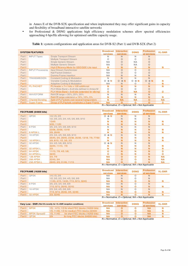
Table 1: system configurations and application areas for DVB-S2 (Part 1) and DVB-S2X (Part 2)
Broadcast services
Interactive services
DSNG Professional services
VL-SNR
Part I INPUT Types Single Transport Stream N N N NPart I Multiple Transport Stream O O O OPart I Single Generic Stream NA O NA OPart I Multiple Generic Stream NA O NA OPart II High Efficiency Mode for GSE/GSE-Lite input N N N N NPart I INPUT Processing Input Stream Synchronizer NA O O OPart I Null Packet Deletion NA O O OPart I Dummy Frame insertion NA N N NPart I TRANSMISSION Constant Coding & Modulation N N N NPart II Variable Coding & Modulation O ! N O ! N O ! N O ! N NPart II Adaptive Coding & Modulation NA N O O NPart II PL PACKET PLHeader = 7+1 bits = 128 additional N N N N NPart I PLH Wide-Band = 8+8 bits defined in Annex M O O O OPart II PLH Wide-Band = 8+8 bits (extended for slicing) O O NA O OPart I WAVEFORM Roll-Off range = 35%, 25%, 20% N N N NPart II Roll-Off range extension = 15%, 10%, 5% N N N N NPart II Channel Bonding Split of PLPackets over several transponders N NA NA O NAPart II Super Frame Group of PLPackets constitutes a Super Frame NA O O O O
N = Normative, O = Optional, NA = Not Applicable
Broadcast services
Interactive services
DSNG Professional services
VL-SNR
Part I QPSK 1/4,1/3, 2/5 O ! N N N NPart I 1/2, 3/5, 2/3, 3/4, 4/5, 5/6, 8/9, 9/10 N N N NPart II 13/45 N N N N NPart II 9/20, 11/20 N N N N NPart I 8 PSK 3/5, 2/3, 3/4, 5/6, 8/9, 9/10 N N N NPart II 23/36, 25/36, 13/18 N N N N NPart II 8 APSK-L 5/9, 26/45 N N N N NPart I 16 APSK 2/3, 3/4, 4/5, 5/6, 8/9, 9/10 O ! N N N NPart II 26/45, 3/5, 28/45, 23/36, 25/36, 13/18, 7/9, 77/90 N N N N NPart II 16 APSK-L 5/9, 8/15, 1/2, 3/5, 2/3 N N N N NPart I 32 APSK 3/4, 4/5, 5/6, 8/9, 9/10 O ! N N N NPart II 32/45, 11/15, 7/9 N N N N NPart II 32 APSK-L 2/3 N N N N NPart II 64 APSK 11/15, 7/9, 4/5, 5/6, O N N N OPart II 64 APSK-L 32/45 O N N N OPart II 128 APSK 3/4, 7/9 NA O O N NAPart II 256 APSK 32/45, 3/4 NA O O N NAPart II 256 APSK-L 29/45, 2/3, 31/45, 11/15 NA O O N NA
N = Normative, O = Optional, NA = Not Applicable
Broadcast services
Interactive services
DSNG Professional services
VL-SNR
Part I QPSK 1/4,1/3, 2/5 NA N O NPart I 1/2, 3/5, 2/3, 3/4, 4/5, 5/6, 8/9 NA N O NPart II 11/45, 4/15, 14/45, 7/15, 8/15, 32/45 NA N O N NPart I 8 PSK 3/5, 2/3, 3/4, 5/6, 8/9 NA N O NPart II 7/15, 8/15, 26/45, 32/45 NA N O N NPart I 16 APSK 2/3, 3/4, 4/5, 5/6, 8/9 NA N O NPart II 7/15, 8/15, 26/45, 3/5, 32/45 NA N O N NPart II 32 APSK 2/3, 32/45 NA N O N N
N = Normative, O = Optional, NA = Not Applicable
Broadcast services
Interactive services
DSNG Professional services
VL-SNR
Part II BPSK 1/5, 4/15, 1/3 for short FEC blocks (16200 bits) NA O O NA NPart II 1/5, 11/45, 1/3 for medium FEC blocks (32400 NA O O NA NPart II BPSK-Spread2 1/5, 11/45 for short FEC blocks (16200 bits) NA O O NA NPart II QPSK 2/9 for long FEC blocks (64800 bits) NA O O NA N
N = Normative, O = Optional, NA = Not Applicable
SYSTEM FEATURES
FECFRAME (64800 bits)
FECFRAME (16200 bits)
Very Low - SNR (Part II's novelty for VL-SNR reception conditions)
Page 3 of 14
Table 1 summarises (2) the elementary features of both the DVB-S2 system (in grey, EN 302 307-1) and the DVB-S2X system (in orange, EN 302 307-2), and indicates the status of each feature (i.e. Normative, Optional and Not-Applicable) for each targeted application area (i.e. Broadcast Services (DTH), Interactive Services, DSNG, Professional Services and Very-Low SNR delivery).
Modifications to the Physical Layer
Header Modification The DVB-S2 specification defines a satellite transmission system using a single carrier signal transmitting a series of physical layer packets. Each packet carries a payload protected by a forward error correction (FEC) encoding scheme (in this case a concatenation of LDPC and BCH). This is preceded by a physical layer header (PL-Header) allowing DVB-S2 demodulators to achieve synchronisation with the transmitted signal. Additionally, the PL-Header signalling provides an indication of the MODCOD scheme used in the payload, the presence of pilot signals and the FEC frame length. A new physical layer header (based on the original DVB-S2 header) has been designed extending the signalling from 7 bits to 8 bits. This has enabled the definition of more MODCOD schemes, allowing a finer SNR granularity as well as the introduction of additional MODCOD modes optimised for linear channels. The extended physical layer header also offers improved error-correction capabilities for very low SNR (VL-SNR) operation down to SNR levels as low as -10 dB.
Scrambling Sequences It is not un-common for satellite services to have to contend with a high level of co-channel interference (CCI). Furthermore it is anticipated that, going forward, multi-spot beam satellite payloads, operating in high CCI environments, will become much more common place (especially, but not exclusively, in Ka band). To avoid performance degradations where channel estimation is based solely upon pilots, DVB-S2X proposes a mechanism to mitigate CCI between DVB-S2 and DVB-S2X carriers, by invoking the use of a defined set of scrambling sequences for the broadcast (DTH) profile as well as the professional profiles, that already previously supported this feature in DVB-S2. The default DVB-S2 Gold code (scrambling sequence number 0), and six other Gold codes have been defined for use in these scenarios. A DVB-S2X receiver will try to decode using the default Gold code first and then cycle through the others as required until the correct sequence is found.
New MODCODs and finer SNR granularity The following section shall consider the implications and advantages of the improvement in MODCOD granularity with respect to:
1. Broadcast services (DTH applications) 2. Interactive services (broadband applications) 3. Professional services (DSNG and VLSNR applications)
1) DTH Broadcast services When comparing performance, consideration must be given to the Channel Model in which the transmission is operating. For the purposes of this document, two models are considered, known as models A and B. Channel model A represents an ideal channel consisting of an ideal linearized High Power Amplifier (HPA) acting as a hard limiter to amplitude excursions. This is driven at the optimum operating point for any MODCOD. SNR is expressed as Psat/N, where Psat is the saturated amplifier power and N is the noise contribution within the usable channel bandwidth Bu, where Bu=Rs(1+roll-off), which is set to 36 MHz. In this model noise and spectral efficiency are measured in the total usable bandwidth Bu. This model assumes there is no adjacent channel interference and that no linear distortion is imposed upon the transmission. Channel model B represents a more realistic channel and includes IMUX and OMUX satellite filters (corresponding to a 38 MHz -3dB bandwidth, and channel spacing of 40 MHz), and a more faithful TWTA non-linear model (including both amplitude and phase distortions). This model also incorporates an element of Adjacent Channel Interference (ACI) in both the uplink and downlink paths, with the same symbol rate and roll-off factors as the wanted signal. It is assumed that the TWTA Output Back Off (OBO) is optimised for each MODCOD. The usable signal bandwidth Bu = Rs x (1+roll-off) can be freely optimised, or it can be limited by satellite operator specifications.
2 Being a summary of « table 1 » specified in Part 1 & Part 2 of the ETSI EN 302 307 document, for the purposes of clarity, the notes explaining
the possible misinterpretation of some specific features have not been reproduced. Please refer to the original standard in case of ambiguity.

Figure 1: DVB-S2 and DVB-S2X spectral
Figure 1 illustrates the simulated performanceDVB-S2 is indicated by the green plot and the granularity effect. Figure 1 shows that points fall on the same ideal dotted lines. DVB-S2X adds new 8PSK MODCODs in the SNR range In addition, whilst 16APSK is optional in S2X mandates the use of 16APSK implementation of 16APSK in DVB-S2X represents a mandatory DVB-S2 specification in the SNR region around 10satellite platforms, typically characterised by a C/I available when operating in channels withIn the range of SNR appropriate for broadcast applications, the DVBShannon capacity curve within a dB or soThe performance of a satellite broadcast service is characterised by a link analysis calculation (the link budget). This predicts the performance of the serviceperformance is often described in terms of adetermined by the SNR characteristics of theThe available SNR is not a constant over acontour maps and the characteristics of the transmit and receive earth stations. In addition there is a temporal variation caused by the prevailing weather conditions in the uplink and downlink regions at thA broadcaster computes the minimum available SNR in the year) using appropriate statistical modelling techniques to P.841 as a guide, although other modelling techniques also existDue to its increased MODCOD granularity, DVBoptimising system performance for specific SNR levels.As shown in Figure 1, any SNR can be matched by continuous lines with the stair-case shape connecting the simrate. The figure shows that DVB-S2X, with its finer MODCOD granularity, while DVB-S2 with its coarser granularity suffers from
3 Simulated Roll-off 5%, even though this is not available in DVB4 It should be noted that in the SNR range of interest for broadcasting, each tenth of dB corresponds approximately to 1% of sp5 The continuous lines are constructed as follows: starting from a simulated point at the maximum allowed symbol
efficiency are progressively lowered, and the required SNR reduces by 10Log[Rs/Rs(max)]; when the lower effpreferable in terms of spectral efficiency and SNR, it is selected (the flat part of the staircase). When the symbol rate cansteps become vertical and the maximum granularity gain approaches 14%.
pectral efficiency, at the same roll-off and symbol-rate (channel model A)SNR range typical for broadcasting.
he simulated performance of channel model A in the SNR range of interest for broadcast services.lot and DVB-S2X by the blue plot. The same roll-off is assumed
shows that DVB-S2X and DVB-S2 share a large number of MODCODs, therefore points fall on the same ideal dotted lines.
S2X adds new 8PSK MODCODs in the SNR range from 6 to 8.5 dB covered in DVB-is optional in DVB-S2 for DTH legacy receivers (see violet triangles in
(adding new MODCODs) in the SNR region 9 to S2X represents a significant capacity increase of around 5%
S2 specification in the SNR region around 10 dB (which is a challenging satellite platforms, typically characterised by a C/I of about 13 dB from adjacent satellites).
with SNR levels better than 10 dB. In the range of SNR appropriate for broadcast applications, the DVB-S2X curve faithfully follows the slope of ideal
within a dB or so (4). satellite broadcast service is characterised by a link analysis calculation (the link budget). This
service in terms of receive margin (in dB) above the required thresholdperformance is often described in terms of an availability figure (% availability per annum).determined by the SNR characteristics of the transmission channel to the specific downlink installation and location.The available SNR is not a constant over any given region and is dependent upon the satellite
the characteristics of the transmit and receive earth stations. In addition there is a temporal variation caused by the prevailing weather conditions in the uplink and downlink regions at the time of the transmission.A broadcaster computes the minimum available SNR in the service area for a target service availability (e.g. 99
appropriate statistical modelling techniques (for example, see ITU-R Recommendations P.618, although other modelling techniques also exist).
Due to its increased MODCOD granularity, DVB-S2X offers greater flexibility to the broadcaster with regard to optimising system performance for specific SNR levels.
any SNR can be matched by DVB-S2 and DVB-S2X (as indicated by thecase shape connecting the simulated points (5)), by fine-tuning the transmitted symbol
S2X, with its finer MODCOD granularity, closely matches the ideal blue dotted line, er granularity suffers from a larger “ripple” compared to the ideal dotted green line.
off 5%, even though this is not available in DVB-S2
It should be noted that in the SNR range of interest for broadcasting, each tenth of dB corresponds approximately to 1% of sp
The continuous lines are constructed as follows: starting from a simulated point at the maximum allowed symbol-rate, the symbolefficiency are progressively lowered, and the required SNR reduces by 10Log[Rs/Rs(max)]; when the lower effpreferable in terms of spectral efficiency and SNR, it is selected (the flat part of the staircase). When the symbol rate can
and the maximum granularity gain approaches 14%.
Page 4 of 14
rate (channel model A), in the
of channel model A in the SNR range of interest for broadcast services. off is assumed (3), to better clarify
S2 share a large number of MODCODs, therefore their
-S2 with lower granularity. (see violet triangles in Figure 1), DVB-
to 12 dB. The mandatory significant capacity increase of around 5% over the original
dB (which is a challenging operating area for current Even further increases are
faithfully follows the slope of ideal
satellite broadcast service is characterised by a link analysis calculation (the link budget). This in terms of receive margin (in dB) above the required threshold and the
n availability figure (% availability per annum). The performance is channel to the specific downlink installation and location.
satellite uplink and downlink the characteristics of the transmit and receive earth stations. In addition there is a temporal variation
e time of the transmission. service area for a target service availability (e.g. 99.9% of
R Recommendations P.618 and P.837
S2X offers greater flexibility to the broadcaster with regard to
as indicated by the blue and green tuning the transmitted symbol-
matches the ideal blue dotted line, larger “ripple” compared to the ideal dotted green line.
It should be noted that in the SNR range of interest for broadcasting, each tenth of dB corresponds approximately to 1% of spectral efficiency
rate, the symbol-rate and spectral efficiency are progressively lowered, and the required SNR reduces by 10Log[Rs/Rs(max)]; when the lower efficient MODCOD becomes preferable in terms of spectral efficiency and SNR, it is selected (the flat part of the staircase). When the symbol rate cannot be finely tuned, the

Page 5 of 14
As previously described, in order to ensure that the simulated results were complete and representative, the TM-S2 group introduced the more complete channel model B together with the concept of an enhanced receiver (ER) with linear equalisation. Similar results to those in Figure 1 have been achieved with this model, but in this case the performance “ripple” due to symbol-rate fine-tuning is dependent upon the allocated bandwidth Bu. In particular, when the transmitted symbol-rate approaches the OMUX -3dB bandwidth, the ripple amplitude reduces to around 3% of spectral efficiency (SE) because of the equaliser effects. In summary, when specific SNR targets are to be met, DVB-S2X reduces the DVB-S2 losses due to its finer MODCOD granularity. The DVB-S2X capacity advantage ranges from 0% (6) to 10% (for Rs<<-3dB bandwidth) or to 3% (for Rs approaching -3dB bandwidth). 2) Interactive Services Frequency re-use techniques over multi-spot beam networks allow for the optimal delivery of broadband interactive services over large geographic regions. Indeed, an increased number of High Throughput Satellites (HTS) are being launched to support this technology. In this configuration, due to on-board satellite accommodation limits, the High Power Amplifiers (HPA’s) are typically operated in multi-carrier mode with appropriate back-off applied. Thus the overall end-to-end link can be considered quasi-linear (this assumption is applicable for more than three carriers per HPA, the dual carriers per HPA case being more borderline). The new DVB-S2X specification introduces additional MODCOD features which can take advantage of this mode of transponder operation: Linear MODCODs (indicated by a '-L' suffix in the MODCOD name), which have been optimised for a linear channel in the presence of phase-noise (7). These bring mixed values of gain, in some cases up to about 1 dB better SNR for the same spectral efficiency. In addition, a finer granularity of MODCODs has been introduced, reducing the SNR threshold distances from the 1 to 1.5 dB of DVB-S2 to an average of about 0.4 to 0.5 dB for DVB-S2X. This reduces the system margin required in ACM-based systems. As a normative feature, DVB-S2X mandates the support of a higher modulation order of 64APSK, as opposed to the optional 32APSK of DVB-S2. This results in an expected spectral efficiency gain of up to 10%. Higher order modulations up to 256 points are also optionally available, thus further increasing the potential spectral efficiency for systems where the link budget allows operating at a corresponding higher level of SNR. Very Low SNR (VL-SNR) MODCODs can also be optionally used in DVB-S2X allowing broadband networks to operate in regions affected by heavy atmospheric fading, at higher frequency bands (e.g. Q/V-band) or with small antenna (even mobile) terminals.
Figure 2: Efficiency versus C/Nref (noise integrated over Rs x (1+roll-off))
for the same occupied bandwidth (AWGN linear channel).
6 0% in the case that the selected DVB-S2X MODCOD is also available in DVB-S2 7 See Table H.3 in Annex H.8 of EN 302 307-2, “Phase Noise Masks for Simulation”
Page 6 of 14
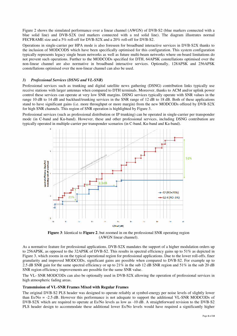
Figure 2 shows the simulated performance over a linear channel (AWGN) of DVB-S2 (blue markers connected with a blue solid line) and DVB-S2X (red markers connected with a red solid line). The diagram illustrates normal FECFRAME size and a 5% roll-off for DVB-S2X and a 20% roll-off for DVB-S2. Operations in single-carrier per HPA mode is also foreseen for broadband interactive services in DVB-S2X thanks to the inclusion of MODCODS which have been specifically optimised for this configuration. This system configuration typically represents legacy single beam networks as well as future multi-beam networks where on-board limitations do not prevent such operations. Further to the MODCODs specified for DTH, 64APSK constellations optimised over the non-linear channel are also normative in broadband interactive services. Optionally, 128APSK and 256APSK constellations optimised over the non-linear channel can also be used. 3) Professional Services (DSNG and VL-SNR) Professional services such as trunking and digital satellite news gathering (DSNG) contribution links typically use receive stations with larger antennas when compared to DTH terminals. Moreover, thanks to ACM and/or uplink power control these services can operate at very low SNR margins. DSNG services typically operate with SNR values in the range 10 dB to 14 dB and backhaul/trunking services in the SNR range of 12 dB to 18 dB. Both of these applications stand to have significant gains (i.e. more throughput or more margin) from the new MODCODs offered by DVB-S2X for high SNR channels. This region of SNR operation is highlighted by Figure 3. Professional services (such as professional distribution or IP trunking) can be operated in single-carrier per transponder mode (in C-band and Ku-band). However, these and other professional services, including DSNG contribution are typically operated in multiple-carrier per transponder scenarios (in C-band, Ku-band and Ka-band).
Figure 3: Identical to Figure 2, but zoomed in on the professional SNR operating region
(AWGN linear channel).
As a normative feature for professional applications, DVB-S2X mandates the support of a higher modulation orders up to 256APSK, as opposed to the 32APSK of DVB-S2. This results in spectral efficiency gains up to 51% as depicted in Figure 3, which zooms in on the typical operational region for professional applications. Due to the lower roll-offs, finer granularity and improved MODCODs, significant gains are possible when compared to DVB-S2. For example up to 2.5 dB SNR gain for the same spectral efficiency or up to 21% in the sub 12 dB SNR region and 51% in the sub 20 dB SNR region efficiency improvements are possible for the same SNR value. The VL- SNR MODCODs can also be optionally used in DVB-S2X allowing the operation of professional services in high atmospheric fading areas.
Transmission of VL-SNR Frames Mixed with Regular Frames The original DVB-S2 PLS header was designed to operate reliably at symbol-energy per noise levels of slightly lower than Es/No = -2.5 dB. However this performance is not adequate to support the additional VL-SNR MODCODs of DVB-S2X which are required to operate at Es/No levels as low as -10 dB. A straightforward revision to the DVB-S2 PLS header design to accommodate these additional lower Es/No levels would have required a significantly higher

Page 7 of 14
transmission overhead to all receive terminals. Considering the fact that mobile and VL-SNR terminals are likely to be only a small minority of the population in any given network, another less onerous solution was deemed to be required in the implementation of the DVB-S2X header architecture in order to economically support the additional modes. An alternative approach which allows regular terminals to use the original DVB-S2 90-symbol PLS Header with only minimal modification to support the larger number of DVB-S2X MODCODs has therefore been adopted. As shown in Figure 4, terminals with higher Es/No thresholds will continue to use the 90-symbol PLS header (i.e. the regular frame sync), and are therefore not penalised by accepting mobile or VL-SNR terminals into the network. Each code frame intended for a mobile or VL-SNR terminal also contains the original 90-symbol PLS header which, in this case, is used to signal to the normal terminals that the following is a frame for a VL-SNR terminal, and specifies the length of the code frame (only two lengths are allowed even though nine VL-SNR MODCODs are defined). A regular terminal can then skip this code frame and look for the next PLS header at the corresponding time with no disruption of frame synchronisation.
Figure 4: Time-multiplex format of a DVB-S2 extension carrier consisting of both regular code frames and code frames for VL-SNR terminals
In Figure 4, the additional VL-SNR frame synchronisation serves two purposes: • to provide burst mode synchronisation of the VL-SNR frames, and • to identify the specific VL-SNR MODCOD for the mobile terminals.
This is accomplished by a set of specifically designed unique words (UW), each identifying one of the nine MODCODs, plus a dummy frame. These unique words are generated from a single mother sequence of 900 symbols, such that an efficient correlation algorithm can be used to detect both the presence the signal and, at the same time, identify the MODCOD. The length of the UW is selected to provide more than adequate margin to achieve synchronisation at the lowest operating SNR range without introducing excessive overhead. For most of the VL-SNR range, π/2-BPSK modulation is used. The two lowest MODCODs are further spread by a factor of 2. To interoperate with legacy DVB-S2 receivers in VCM modes, the length of LDPC codes are modified so that the frame size of the VL-SNR MODCODs, including the 900-symbol frame sync and pilots, is the same as either a QPSK or 16APSK modulated DVB-S2 MODCOD with pilots.
Sharper roll-off The gains achieved from sharper roll-off depend upon the flexibility the operator has to set the optimum symbol rate and the constraints imposed by the satellite operator in terms of uplink spectral mask. Assuming that the operator is totally free to optimise the symbol-rate to increase the spectral efficiency (as illustrated in Figure 7), and using the DTH satellite channel model B and an enhanced receiver, the TM-S2 has calculated that there is no clear benefit to use sharper roll-offs (see Figure 5). Although sharper roll-offs allow higher symbol rates (37 Mbaud) the additional capacity gain is below 2% compared with a 20% roll-off and symbol-rate of 34 Mbaud. Nevertheless, increasing symbol rate may generate interference in adjacent channels, which can be better controlled by sharp roll-offs. New simulation results based on the satellite channel model described in the User Guidelines document TR 102376-2 which includes an additional increase of +8 dB in the uplink ACI and with a symbol rate of 34 Mbaud, have shown that a roll-off of 20% can provide 0.1 - 0.2 dB better performance when compares with 5% roll-off using a fractionally spaced equaliser in the receiver. Note that these results did not cover higher symbol rates. In cases where the satellite operators limit the usable bandwidth (Bu) by invoking the (1+roll-off) (8) rule, then maximum transmittable symbol-rate becomes Bu/(1+roll-off). In this scenario, assuming that within the usable bandwidth, transponder bandwidth limitations are not generating significant distortions (i.e. we are operating as channel model A), then the sharper roll-offs will allow for a proportional increase of the transmitted symbol rate. In this case the spectral efficiency gains roughly account for half of the roll-off difference. This is because the other half of the gain is
8 The transmitted symbol rate Rs must be lower to BW/(1+roll-off) , where BW is the usable bandwidth.
Regular Frame Regular Frame
Standard PLS Header
Key:
Mobile frame Sync
Mobile Frame
Regular Frame

Page 8 of 14
“masked” by the increased noise bandwidth at the receiver. For example, comparing DVB-S2 with roll-off 20% to DVB-S2X with roll-off 5%, the symbol-rate increase is about 14%, however the receiver noise power increases by around 0.6 dB and, overall, the net spectral efficiency gain is reduced to around 7%.
Figure 5: Effect of sharper roll-offs on channel model B, “free symbol-rate optimisation”: DVB-S2X (red and green
curves) compared with DVB-S2 at roll-off 20%
Figure 6. Effect of sharper roll-offs on channel model B, “1+roll-off rule” with Bu=36 MHz: DVB-S2X (red and green
curves) compared with DVB-S2 at roll-off 20%
To validate such results on the more complete channel model B, and to compare the available capacity with that of Figure 5 (free symbol-rate optimisation), the spectral efficiency with roll-off’s of 5%, 10% and 20% have been compared imposing the (1+roll-off) rule over Bu=36 MHz. For a 5% roll-off the measured gain when compared to a 20% roll-off approached 6.5%, only slightly less than the gain on the simpler channel model A, without bandwidth limitation distortions (9).
9 When comparing the 20% roll-off in Figure 5 with the 5% roll-off in Figure 6, the (1+roll-off) rule with a Bu=36 MHz limitation produces a
negligible performance penalty. In the case that Bu is increased (e.g. from -1 dB transponder bandwidth to the channel spacing), then the roll-off gain progressively reduces and approaches the case with free symbol-rate optimisation. To compare results of Figure 6 with Figure 1 (both at roll-off 5%), SNRs in Figure 1 are to be reduced by 10*log(38/36)=0.2 dB, and SE divided by 38/36=1.0555. After such scaling, it can be deduced for example that 8PSK rate 5/6 on channel A performs 0.7 dB better than on channel B.

Similarly, in broadband and professional applications, the gains from sharper rollnetwork configuration Particularly, whether the broadband network is operated as an ‘open system’ or as a ‘closed system’ and whether the on-board HPAs are operated in single carrier or multiexpected that the (1+roll-off) rule applies, as near optimum performance transponder do not overlap in frequency. In singldifferent uplink stations, the satellite operator may impose a maximum occupied bandwidth so that again the off) rule applies. When the (1+roll-off) ruleare not generating significant distortions, sharper rollIn this case the spectral efficiency gain depends off with DVB-S2X with 5% roll-off, the symbolthe net gain in the professional region varies from 8% (SNR=10In ’closed systems’, where the network is fully carrier per HPA mode, the operator itself may decide on how to optimise the overall system capacity. In
Use of Enhanced Receivers Basic equalisation technologies are implemented in most model B, encourages manufacturers to include even more advanced receivers, broadcasters will often be able to these equalisers. Computer simulations on channel model receivers, ERs) demonstrated spectral ein Figure 7. Nevertheless, the standard does not specify the receiver's implementation, depends upon the precise receiver implementation, the channel distortionThus we can say that the introduction of the advanced equaliser concept will bring benefits but that it is up to the implementers to realise those benefits through careful optimisation. transmit spectral mask bandwidth is significantly less than the transponder separationrule imposed by some satellite operators)
Figure 7: Spectral efficiency vs symbol rate for recereceiver
Variable Coding and Modulation DVB-S2X makes variable coding and modulation (VCM) MODCODs on a frame by frame basis. This allows operators to adjust transmission robustness versus efficiency according to the prevailing atmospheric conditions or even requirements (e.g. a highly robust standard definition TV
Similarly, in broadband and professional applications, the gains from sharper roll-off depend whether the broadband network is operated as an ‘open system’ or as a ‘closed
oard HPAs are operated in single carrier or multi-carrier mode. In multiapplies, as near optimum performance is achieved when the carriers within the
transponder do not overlap in frequency. In single carrier mode, when the network is shared by different operators using different uplink stations, the satellite operator may impose a maximum occupied bandwidth so that again the
off) rule applies, and assuming that within the transponder bandwidth limitations are not generating significant distortions, sharper roll-offs allow a proportional increase of the transmitted symbol rate.
gain depends upon the SNR region. For example, comparing off, the symbol-rate increase is 14%, the receiver noise power increases by 0
the net gain in the professional region varies from 8% (SNR=10 dB) to 11% (SNR=20 dB). , where the network is fully utilised by one operator, and the satellite payload is operated in single
carrier per HPA mode, the operator itself may decide on how to optimise the inter-transponder interference in order to n this case, the same conclusions as for the corresponding DTH case apply.
technologies are implemented in most DVB-S2 chipsets. DVB-S2X, through the use of channel s to include even more advanced equalisers by default. As such, when using the new
receivers, broadcasters will often be able to optimise to a higher symbol rate within the correction capability of
odel B, using free symbol-rate optimisation with adaptive efficiency gains of around 7% to 9% over conventional receivers (CR), as shown
Nevertheless, the standard does not specify the receiver's implementation, hence the upperreceiver implementation, the channel distortions and the satellite operator's operating rules.
Thus we can say that the introduction of the advanced equaliser concept will bring benefits but that it is up to the implementers to realise those benefits through careful optimisation. Of course, the equaliser is less critical when the transmit spectral mask bandwidth is significantly less than the transponder separation (e.g. following Rrule imposed by some satellite operators).
symbol rate for receivers with and without linear equalisation (with = enhanced receiver, ER, without = conventional receiver, CR).
variable coding and modulation (VCM) mandatory for DTH applications, thus enabon a frame by frame basis. This allows operators to adjust transmission robustness versus efficiency
atmospheric conditions or even to tailor services according to quality of service standard definition TV channel simulcast with an ultra-high definition
Page 9 of 14
off depend upon the broadband whether the broadband network is operated as an ‘open system’ or as a ‘closed
carrier mode. In multi-carrier mode, it is achieved when the carriers within the
e carrier mode, when the network is shared by different operators using different uplink stations, the satellite operator may impose a maximum occupied bandwidth so that again the (1+roll-
in the transponder bandwidth limitations we offs allow a proportional increase of the transmitted symbol rate.
ple, comparing DVB-S2 with 20% roll-rate increase is 14%, the receiver noise power increases by 0.6 dB, and
by one operator, and the satellite payload is operated in single transponder interference in order to
the same conclusions as for the corresponding DTH case apply.
S2X, through the use of channel As such, when using the new
within the correction capability offered by
with adaptive equalisation (in enhanced gains of around 7% to 9% over conventional receivers (CR), as shown
hence the upper symbol rate limit still s and the satellite operator's operating rules.
Thus we can say that the introduction of the advanced equaliser concept will bring benefits but that it is up to the ser is less critical when the
(e.g. following Ru=Rs(1+rolloff)
vers with and without linear equalisation (with = enhanced
thus enabling the change of on a frame by frame basis. This allows operators to adjust transmission robustness versus efficiency
services according to quality of service high definition TV channel).
By sacrificing the picture quality during heavy rain fading (increase the overall system spectral efficiencyservice to the end user. Two examples of comparative performance gains are presented in Table below
Study Case
Parameter Transponder Spacing (MHz) Transponder Bandwidth (MHz)Total Number of TranspondersAggregate bandwidth (MHz) Air Interface (DTH Profile) Transmission Mode Average bit Rate per stream (Mbits/sec)HEVC Availability
Symbol Rate (MBaud) MODCODs
Total number of UHD video streams (TV channels) delivered by the satellite
Main improvements at the Upper Protocol Layers
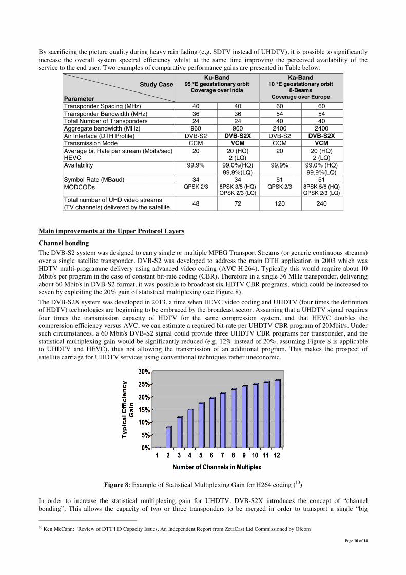
Channel bonding The DVB-S2 system was designed to carry single or multiple MPEG Transport Streams (or generic continuous streams) over a single satellite transponder. DVBHDTV multi-programme delivery using Mbit/s per program in the case of constant bitabout 60 Mbit/s in DVB-S2 format, it was possible to broadcast seven by exploiting the 20% gain of statistical The DVB-S2X system was developed in 2013, of HDTV) technologies are beginning to be embraced by the broadcast sectorfour times the transmission capacity of HDTV for the same compression system, and that HEVC doubles the compression efficiency versus AVC, we can estimate a required bitsuch circumstances, a 60 Mbit/s DVB-S2 signal could prostatistical multiplexing gain would be significantly reduced (e.g. 12% instead of 20%, assuming to UHDTV and HEVC), thus not allowing the transmission of an additional program. satellite carriage for UHDTV services using conventional techniques rather uneconomic.
Figure 8: Example of Statistical Multiplexing Gain for H264 coding
In order to increase the statistical multiplexing gain for UHDTV, bonding”. This allows the capacity of two or three transponders 10 Ken McCann: “Review of DTT HD Capacity Issues, An Independent Report from ZetaCast Ltd Commissioned by Ofcom
By sacrificing the picture quality during heavy rain fading (e.g. SDTV instead of UHDTV), it is possible fficiency whilst at the same time improving the perceived availability of the
Two examples of comparative performance gains are presented in Table below
Study Case Ku-Band
95 °E geostationary orbit Coverage over India
Ka10 °E geostationary orbit
8-Coverage over Europe
40 40 60 Transponder Bandwidth (MHz) 36 36 54 Total Number of Transponders 24 24 40
960 960 2400 DVB-S2 DVB-S2X DVB-S2
CCM VCM CCM Average bit Rate per stream (Mbits/sec) 20 20 (HQ)
2 (LQ) 20
99,9% 99,0%(HQ) 99,9%(LQ)
99,9%
34 34 51 QPSK 2/3 8PSK 3/5 (HQ)
QPSK 2/3 (LQ) QPSK 2/3
video streams (TV channels) delivered by the satellite 48 72 120
Upper Protocol Layers
S2 system was designed to carry single or multiple MPEG Transport Streams (or generic continuous streams) DVB-S2 was developed to address the main DTH application in 2003
elivery using advanced video coding (AVC H.264). Typically this wouldcase of constant bit-rate coding (CBR). Therefore in a single 36 MHz transponder, delivering
S2 format, it was possible to broadcast six HDTV CBR programs, which could be increased to tatistical multiplexing (see Figure 8).
S2X system was developed in 2013, a time when HEVC video coding and UHDTV (four times the definition technologies are beginning to be embraced by the broadcast sector. Assuming that a UHDTV signal requires
transmission capacity of HDTV for the same compression system, and that HEVC doubles the compression efficiency versus AVC, we can estimate a required bit-rate per UHDTV CBR program of 20Mbit/s. Under
S2 signal could provide three UHDTV CBR programs per transponder, and the statistical multiplexing gain would be significantly reduced (e.g. 12% instead of 20%, assuming to UHDTV and HEVC), thus not allowing the transmission of an additional program. This makes the prospect of satellite carriage for UHDTV services using conventional techniques rather uneconomic.
: Example of Statistical Multiplexing Gain for H264 coding (
In order to increase the statistical multiplexing gain for UHDTV, DVB-S2X introduces the concept ofthe capacity of two or three transponders to be merged in order
Ken McCann: “Review of DTT HD Capacity Issues, An Independent Report from ZetaCast Ltd Commissioned by Ofcom
Page 10 of 14
SDTV instead of UHDTV), it is possible to significantly whilst at the same time improving the perceived availability of the
Two examples of comparative performance gains are presented in Table below. Ka-Band
°E geostationary orbit -Beams
Coverage over Europe 60 54 40
2400 DVB-S2X
VCM 20 (HQ) 2 (LQ)
99,0% (HQ) 99,9%(LQ)
51 8PSK 5/6 (HQ)
QPSK 2/3 (LQ)
240
S2 system was designed to carry single or multiple MPEG Transport Streams (or generic continuous streams) he main DTH application in 2003 which was
. Typically this would require about 10 rate coding (CBR). Therefore in a single 36 MHz transponder, delivering
HDTV CBR programs, which could be increased to
when HEVC video coding and UHDTV (four times the definition . Assuming that a UHDTV signal requires
transmission capacity of HDTV for the same compression system, and that HEVC doubles the rate per UHDTV CBR program of 20Mbit/s. Under
CBR programs per transponder, and the statistical multiplexing gain would be significantly reduced (e.g. 12% instead of 20%, assuming Figure 8 is applicable
This makes the prospect of
(10)
introduces the concept of “channel er to transport a single “big
Ken McCann: “Review of DTT HD Capacity Issues, An Independent Report from ZetaCast Ltd Commissioned by Ofcom

Page 11 of 14
transport stream” (typically a large statistically multiplexed MPTS). It should be noted that this functionality is only available if the receiver is equipped with multiple tuners to enable the simultaneous acquisition of data streams from different transponders. These types of receivers are already becoming more commonplace with the advent of functionalities such as ‘picture-in-picture’ and ‘watch one program, record another’. To illustrate the potential gains of channel bonding, consider a typical 36MHz transponder carrying three UHDTV services. If the transponder is bonded with a second transponder then the channel capacity increases to six services. Reference to Figure 8 shows that the statistical multiplexing gain rises from around 12% to 19%, an improvement of 7%. Bonding a third transponder could take the gain to 24%, an overall gain of 12% when compared to the original single transponder. A further potential application of channel bonding is in its ability to gather spare capacity across transponders. Often, due to the placement of carriers on a shared transponder, areas of spectrum become sterilised between carriers and cannot be usefully deployed. Channel bonding offers the potential of accumulating this space and reconstituting it into usable capacity, thus further improving transponder usage. It should be noted that the DVB-S2X supports the channel bonding only in conjunction with Constant Coding & Modulation (CCM).
Generic Stream Encapsulation (GSE) DVB-S2X includes the possibility to carry audio-visual and data services in full-IP format, using the GSE or GSE-lite adaptation protocol layer instead of a traditional transport stream. This can increase the system flexibility in the future, when the services from various networks (such as terrestrial broadband networks and satellites) converge to the IP format. For example the broadcasting services from the satellite could be injected in a full-IP home network, and seamlessly routed to the user together with the interactive broadband services (x-DSL or optical-fibre). The support of GSE or GSE-lite also significantly reduces the layer-2 encapsulation overhead thus bringing additional gains in terms of net system capacity.
Optional Super-Framing An optional super-framing structure is available in DVB-S2X as described fully in Annex E of the standard. The use of the super-framing structure has the following benefits:
• Increased resilience to co-channel interference caused by other beams, due to super-frame-wide scrambling and regular (and orthogonal) pilot symbol insertion that can be aligned in time on different beams
• Support of synchronisation algorithms by the regular insertion of reference data fields, which leads to enhanced receiver performance under severe channel conditions such as VL-SNR or link interruptions
• Future proof frame design with signalling of the super-frame content format, which is able to accommodate and support:
• Interference mitigation techniques • Beam hopping operations • Single-format or multi-format transmission per carrier • Introduction of different profiles where receivers can clearly identify supported and unsupported
super-frame content formats The following profiles are currently specified, while the remaining 11 profiles are reserved for future use or proprietary content:
Profile Description 0 DVB-S2X including a modified VL-SNR burst mode frame with larger pilot fields 1 DVB-S2 legacy format 2 Format with Bundled PL-FRAMEs (64800 payload size) of constant size and location 3 Format with Bundled PL-FRAMEs (16200 payload size) of constant size and location 4 Flexible format with VL-SNR PL-Header tracking and different PL-Header protection levels
The super-frame structure corresponding to the first profile introduces an extra overhead of only 0.12% when compared to common DVB-S2X transmission. For future applications, the super-frame structure supports orthogonal start of super-frame (SOSF) and pilot fields by using Walsh-Hadamard sequences. A set of unique orthogonal sequences can be assigned to co-channel carriers within a multi-spot beam network (a unique sequence per beam). Profiles 2 and 3 allow constant and aligned PL-FRAME sizes to be maintained over co-channel carriers. This enables interference mitigation techniques to be employed at the receiver terminal (e.g. Multi-User Detection, MUD) as well as at the Gateway (GW pre-coding techniques) as presented in Figure 9. Both techniques, depending upon the system configurations, have the potential to provide capacity gains between 20% and 100%, with pre-coding offering the greatest advantage. In order to benefit from these gains they should be used in combination with more aggressive frequency re-use schemes, in particular, with full frequency re-use and two colour schemes.

Figure 9: Functional description of GW
In addition to interference mitigation, the new supertechnique is currently being considered for useincrease the flexibility of resource allocation over illuminating the different beams in a time divisionbeams are simultaneously illuminated. The complete set of beams within the so called “beam-hopping” window.
GWY
3
The GW computes that channel precoding
given the reported channel responses reported by each
terminal in the coverage
Functional description of GW-based Pre-coding techniques
In addition to interference mitigation, the new super-frame structure supports the idea of satelliteconsidered for use in broadband networks (through proprietary solutions) with the scope to
increase the flexibility of resource allocation over both geographic coverage and over time. time division fashion with bursts of data, such that at any given time only a set of
beams are simultaneously illuminated. The complete set of beams within the overall coverage window. Initial system simulation results show that beam hopping can better track
C
I1 I2
terminals estimate the end
frequency response for C, I1 and I2, i.e. Hi1,Hi2 and Hi3interference channel
responses for full frequency
Hi1, Hi2, ….HiN (N complex numbers):reported on the return channels when significant changes are detected – worst case every ~ 1 sec
in deep fading conditions similarly to the ACM signaling
1
2
The GW computes that precoding matrix
given the reported channel responses reported by each
terminal in the coverage
Page 12 of 14
coding techniques
s the idea of satellite beam hopping. This in broadband networks (through proprietary solutions) with the scope to
verage and over time. The concept consists of that at any given time only a set of
rage will obtain illumination ystem simulation results show that beam hopping can better track
Usererminals estimate the end-to-end channel
frequency response for C, I1 and I2, i.e. Hi1,Hi2 and Hi3- up to 10~15 interference channel
responses for full frequency –re-use
systems
channels when significant worst case every ~ 1 sec
in deep fading conditions similarly to the ACM

Page 13 of 14
the time-variant nature of user demand within the coverage when compared to other techniques (such as flexible HPAs). From the air interface point of view, beam hopping requires the receivers to work in a burst mode, as each terminal will only see the desired carrier for a fraction of the beam hopping window. This is made possible with super-framing due to the structure of the payload data container and the data gaps which terminate the super-frame with dummy symbols (in formats 2 and 3) or dummy frames of arbitrary size (in format 4). Thus, consecutive containers act as bursts plus guard time, which allow the satellite payload to re-configure according to the beam to be illuminated.
Conclusions
The 2003 DVB-S2 standard already offers excellent spectral efficiency performance with respect to the Shannon-limit, particularly for DTH applications, and provided significant efficiency gains (of around 30%) when compared to the previous DVB-S system. DVB-S2X represents an evolution and refinement of the DVB-S2 standard rather than a fundamental step change in the technology. Therefore, in general, DVB-S2X cannot provide such large advances in performance as offered by the DVB-S to DVB-S2 transition and, indeed, that is not its intention. However, the changes presented in DVB-S2X do offer significant advances and opportunities, to service providers, particularly in the areas of:
• New generation DTH broadcast services (e.g. VCM with simulcasting or channel bonding in support of UHDTV)
• Broadband services (e.g. multi-beam hopping applications supported by new super-framing structure) • Professional services (e.g. finer MODCOD granularity offering more flexible SNR usage and VLSNR
applications) Finally, we shall summarise the advantages and potential gains for each application area in turn. DTH DVB-S2X fine-tunes both the physical and the upper protocol layers of DVB-S2, producing a highly attractive package for those service operators intending to launch new generation services requiring new receivers. The typical application is the launch of UHDTV services based on the new HEVC coding algorithms. The table below summarises the spectral efficiency gains of DVB-S2X versus DVB-S2 for UHDTV broadcasting.
DVB-S2X Spectral Efficiency gain vs DVB-S2 (channel model B, enhanced receiver for DVB-S2 and DVB-S2X) DVB-S2X Characteristic (1+roll-off ) rule; Bu =36 MHz Free symbol-rate
optimisation Physical Layer
Better MODCODs
0% (for SNR<10 dB) 5% or larger (SNR>10 dB), (11)
0% (for SNR<10 dB) 5% or larger (SNR>10 dB), (12)
Finer granularity 0% (8) to 10% 0% (8) to 3% Sharper roll-off (5% vs. 20%)
6% to 7% 2%
System Layers
Channel bonding (two or three transponders)
StatMux gain (UHDTV-1): 7% to 12% Plus the possibility to cumulate spare capacity for additional programs
VCM simulcast (UHDTV-1 and SDTV)
Up to 50% in geographical areas with a high level of atmospheric attenuation in Ku frequency band (A higher gain is expected in Ka frequency band)
Broadband For legacy (single beam) broadband networks, DVB-S2X fine-tunes both the physical and the upper protocol layers of DVB-S2. However, the best expected performance gains are foreseen for future multi-spot beam systems especially in the Ka-band multi-spot environment where aggressive spectrum re-use schemes together with advanced interference mitigation techniques can significantly boost the capacity (up to 100%) when compared to more conventional systems. This is made possible due to the new super-framing structure presented in DVB-S2X. In addition, by utilising the beam hopping technology supported by the new super framing structure, it is envisioned that dynamic resource allocation over the coverage area will be able to be greatly improved. 11 Reference DVB-S2 without (optional) 16APSK. In case of available SNR=12 dB, the DVB-S2X better MODCODs gain may increase 10% to 15%
(Figure 1).

Page 14 of 14
Professional Services Professional services will benefit from finer MODCOD granularity allowing much more flexibility in system design with regard to trading throughput, availability and SNR. This will allow for more the efficient deployment of DSNG and contribution links and the more flexible usage of transponder capacity. Similarly, the lower roll-off filters will give the flexibility to space carriers closer together, again, potentially increasing transponder usage. VLSNR MODCODS and higher order constellation schemes extend both the low and high end SNR operating region providing potential new application areas, particularly for VSAT (VLSNR) and high throughput trunk/contribution links (high order constellation schemes).


