7
White Paper Arc Flash Studies and Transfer Switch Serviceability

White Paper
Arc Flash Studies and Transfer Switch Serviceability

2
This paper provides an overview of arc flash hazards and measures for mitigating associated risks. It also reviews potential outcomes for arc flash risk assessments and suggests steps to provide for transfer switch serviceability to ensure reliable service.
ARC FLASH HAZARDS
Maintaining electrical equipment presents safety risks to workers that must be managed in accordance with government regulations and industry codes. Arc flash events present serious hazards. Arc flashes result from arcing faults, which occur when a low resistance path between conductive elements allows current to pass through air. When such faults occur, they release energy in the form of heat and pressure, which can injure people and cause property damage. In addition, arc flashes emit radiation that can damage eyes and burn skin. Because arc faults can occur at relatively low current levels, they may not trip overcurrent protection devices.
The air temperatures associated with arc faults can be extremely high and the associated heat can cause severe burns to people located proximate to the flash. Exposure to this heat is measured in calories per square centimeter (cal/cm2). The amount of heat required to produce a second degree burn is 1.2 cal/cm2.
It is important to understand that the heat associated with arc flash causes air and materials to expand rapidly and can vaporize metals. For instance, the heat of an arc flash will vaporize metals such as silver and copper, which rapidly expand, expelling both copper vapors and droplets of molten metal that cause spot burns and ignite clothing. Arc faults also generate pressure waves that can throw a person across a room as well as damage lungs and eardrums. Consequently, arc flash events can cause serious injuries to workers.
ARC FLASH REGULATIONS AND STANDARDS
In 1970, the United States Congress enacted the Occupational Health and Safety Act. This statute requires that employers provide workplaces that are free of recognized hazards, including electrical hazards. The Act also created the Occupational Health and Safety Administrations (OSHA), which issues workplace safety regulations and enforces their implementation. Electrical safety regulations are found in the US Code of Federal Regulations, specifically 29 CFR 1910, which addresses workplace safety, and 29 CFR 1926, which addresses safety in the construction industry. Analogous regulations exist in other countries and jurisdictions.
To assist OSHA in regulating electrical safety, the National Fire Protection Association developed NFPA 70E: Standard for Electrical Safety in the Workplace. The first edition was published in 1979, and the current edition became effective in August of 2017. The standard differs in focus from the OSHA regulations. Whereas OSHA regulations focus on safety requirements, NFPA 70E focuses on evaluating and mitigating risks. Doing so requires that a hazard assessment be conducted for arc flash risks at electrical equipment located throughout the workplace. Both NFPA 70E and IEEE 1584-2002 - Guide for Performing Arc Flash Hazard Calculations provide methods for performing the necessary calculations.
The content of this document is provided for informational purposes only. The information cannot be used to substitute proper review of safety standards and regulations, proper evaluation of site conditions, or proper implementation of appropriately designed electrical safety and maintenance programs and procedures. A qualified electrical safety expert should be consulted prior to designing and implementing work practices for servicing electrical equipment.
3
ARC FLASH MITIGATION MEASURES
In order to assess the presence and extent of electrical safety risks in a workplace, an arc flash risk assessment must be completed in accordance with Article 130.5 of NFPA 70E. Principle safety measures for controlling arc flash risks that may be found include: (1) labelling equipment with device-specific hazard and safety information, (2) establishing boundary zones for persons working near equipment, and (3) using suitable personal protective equipment (PPE).
Equipment Labelling
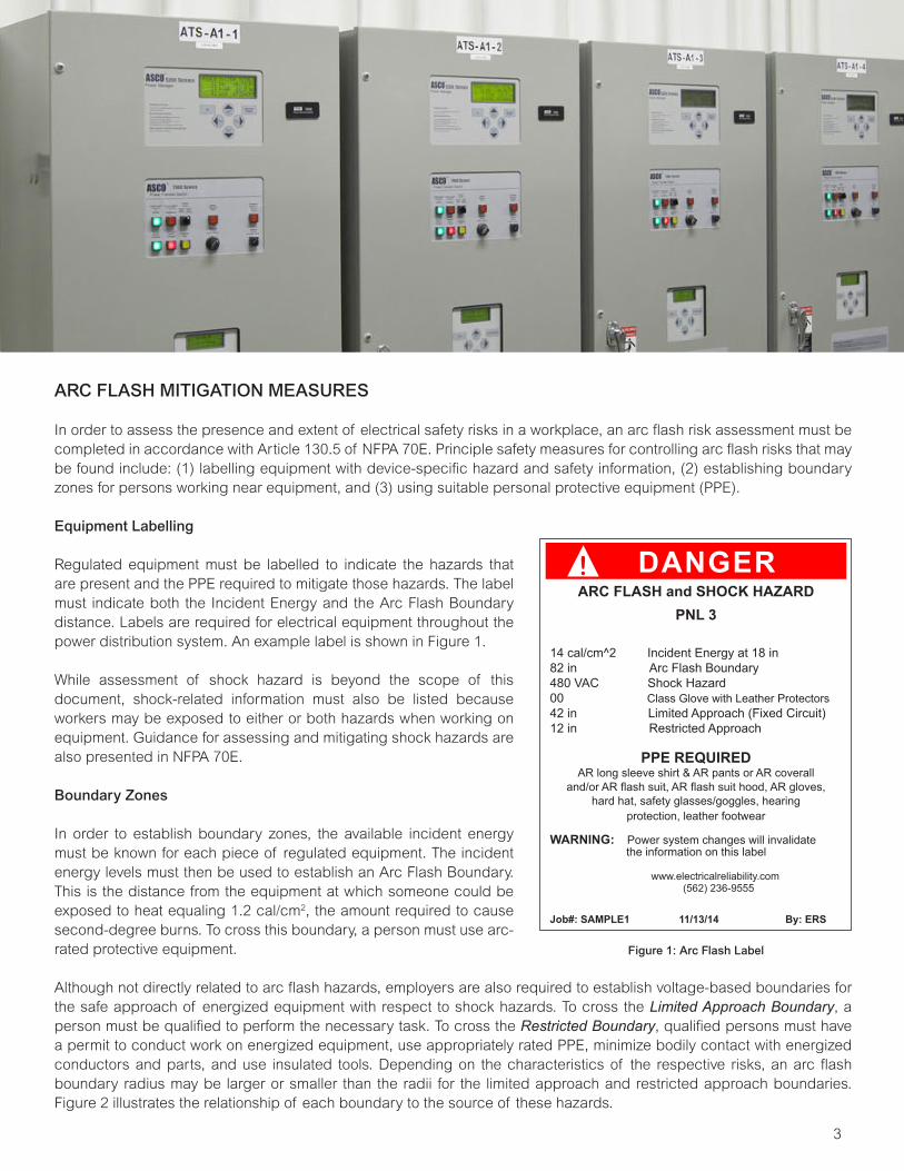
Regulated equipment must be labelled to indicate the hazards that are present and the PPE required to mitigate those hazards. The label must indicate both the Incident Energy and the Arc Flash Boundary distance. Labels are required for electrical equipment throughout the power distribution system. An example label is shown in Figure 1.
While assessment of shock hazard is beyond the scope of this document, shock-related information must also be listed because workers may be exposed to either or both hazards when working on equipment. Guidance for assessing and mitigating shock hazards are also presented in NFPA 70E.
Boundary Zones
In order to establish boundary zones, the available incident energy must be known for each piece of regulated equipment. The incident energy levels must then be used to establish an Arc Flash Boundary. This is the distance from the equipment at which someone could be exposed to heat equaling 1.2 cal/cm2, the amount required to cause second-degree burns. To cross this boundary, a person must use arc-rated protective equipment.
Although not directly related to arc flash hazards, employers are also required to establish voltage-based boundaries for the safe approach of energized equipment with respect to shock hazards. To cross the Limited Approach Boundary, a person must be qualified to perform the necessary task. To cross the Restricted Boundary, qualified persons must have a permit to conduct work on energized equipment, use appropriately rated PPE, minimize bodily contact with energized conductors and parts, and use insulated tools. Depending on the characteristics of the respective risks, an arc flash boundary radius may be larger or smaller than the radii for the limited approach and restricted approach boundaries. Figure 2 illustrates the relationship of each boundary to the source of these hazards.
! DANGERARC FLASH and SHOCK HAZARD
PNL 3
14 cal/cm^2 Incident Energy at 18 in82 in Arc Flash Boundary480 VAC Shock Hazard00 Class Glove with Leather Protectors42 in Limited Approach (Fixed Circuit)12 in Restricted Approach
PPE REQUIREDAR long sleeve shirt & AR pants or AR coverall
and/or AR flash suit, AR flash suit hood, AR gloves,hard hat, safety glasses/goggles, hearing
protection, leather footwear
WARNING: Power system changes will invalidate the information on this label
www.electricalreliability.com (562) 236-9555
Job#: SAMPLE1 11/13/14 By: ERS
Figure 1: Arc Flash Label
The OSHA regulations obligate employers to ensure that safe working conditions are provided for workers. Safe working conditions cannot be established if an up-to-date assessment of electrical hazards has not been completed in accordance with the OSHA regulations and the NFPA 70E standard.

4
Figure 2: Arc Flash, Limited Approach, and Restricted Approach Boundaries. See NFPA 70E Informative Annex C for complete information.
Personal Protective Equipment
The level of required PPE increases with the degree of arc flash hazard. NFPA 70E Table 130.7(C)(15)(c) specifies four categories of protective gear, based on a range of incident energies. For informational purposes, these categories are summarized below.
Category Description
1 Arc-Rated Clothing Minimum Arc Rating of 4 cal/cm2
2 Arc-Rated Clothing Minimum Arc Rating of 8 cal/cm2
3 Arc-Rated Clothing Selected so the Minimum System Arc Rating is 25 cal/cm2
4 Arc-Rated Clothing Selected so the Minimum System Arc Rating is 40 cal/cm2
*The PPE requirements also variously include arc-rated face shields or hoods, hardhats and hardhat liners, safety goggles or glasses, hearing protection, leather or insulated gloves, leather footwear and other protective gear. Consult OSHA regulations and the NFPA 70E standard for detailed information before selecting PPE.
Arc flash boundary
Limited approachboundary
Any point on anexposed, energizedelectrical conductoror circuit part
Restricted approachboundary
An important objective of any arc flash mitigation program is to identify PPE that will adequately protect workers. Nevertheless, it is important to recognize that higher levels of PPE may complicate service events by introducing new concerns or impacting work productivity. For instance, face and eye protection measures could make seeing the equipment and work area more difficult. The reduced manual dexterity offered by arc-resistant gear could limit workers’ abilities to complete tasks requiring fine motor skills. Likewise, placing a worker in Level 4 gear (Figure 3) for a protracted length of time could introduce heat stresses that require mitigation. For these reasons, it can be beneficial to review opportunities for reducing arc hazards at equipment locations.

5
ARC FLASH RISK ASSESSMENT
Article 130.5 of NFPA 70E specifies that an arc flash study shall be performed to identify arc flash hazards. If these hazards are present, the assessment shall also determine the likelihood and severity of injury and damage as well as protective measures, including PPE. The assessment must be done whenever changes occur to a facility’s electrical system or every 5 years, whichever occurs first.
Article 130.5 does not directly prescribe how arc flash assessments shall be completed. However, Appendix D of the NFPA 70E standard summarizes several approaches, including IEEE 1584-2002 - Guide for Performing Arc Flash Hazard Calculations. The incident energy values resulting from the calculations presented in these documents are used to produce labels like the example shown in Figure 1 above.
With regard to the PPE that must be specified on the label, Article 130.5 offers users two methods for selecting PPE. One is the Arc Flash PPE Categories Method; the other is the Incident Energy Analysis Method. Both methods are described in the following sections.
Arc Flash PPE Categories Method
The Arc Flash PPE Categories Method is described in Article 130.7(C)(15) of NFPA 70E, which specifies that Table 130.7(C)(15)(a) may be used to determine the arc flash PPE category for ac equipment, subject to the listed maximum short circuit currents, maximum fault-clearing times, and minimum working distances. However, an incident energy analysis is required in lieu of table usage whenever:
• Available fault currents and/or fault clearing times exceed values listed on the table• Tasks may be conducted at less than the listed working distances
Incident Energy Analysis Method
Whether or not equipment qualifies for the NFPA Arc Flash PPE Categories Method, the Incident Energy Analysis Method may be used to calculate incident energies for specific tasks and assign corresponding PPE levels. However, Article 130.5(F) makes it clear that either method, but not both, may be used to specify PPE for servicing a specific device.
As previously noted, Article 130.5 refers users to Appendix D for information about calculating incident energy. In turn, Appendix D refers users to guidance that includes IEEE 1584. The information needed to assess arc flash hazards includes the following:
• Utility transformer ratings• Ratings for Emergency generators• Up-to-date one-line drawings of the power system• Lengths and diameters of conductors• Specifications and settings for overcurrent protection devices (OCP)• Results of an up-to-date OCP selective coordination study
The information is used to establish the available fault currents and their durations at equipment in the power distribution system, including power transfer switches. Using formulas in NFPA 70E Appendix D and/or IEEE 1584, the potential Incident Energy values are calculated. The resulting values are used to specify both corresponding the Arc Flash Boundary and the PPE level required to service equipment. Thereafter, labels presenting the necessary information are applied to individual equipment.
Figure 3: A technician in Level 4 PPE.

6
ARC FLASH STUDY OUTCOMES
When the Arc Flash risk assessment requirements are met, PPE requirements will be labeled on equipment requiring service, including transfer switches. One outcome could be labels indicating potential incident energy ratings that exceed the capabilities of available PPE, thus preventing service of energized equipment. Because the incident energy values are also required to be evaluated for the emergency source of the transfer switch, its serviceability can often be retained while loads continue to be powered.
The Emergency source could present lower incident energy values, if the power source is an engine generator and depending on its characteristics. Lower incident energy levels can enable service to occur while a transfer switch is connected to the Emergency power source. In that instance, work procedures can be developed for transferring to Emergency and de-energizing the Normal source before undertaking transfer switch service. Using a Closed Transition Transfer can maintain electrical continuity during transfer. Where appropriate, check whether PPE levels were derived from NFPA tables or incident energy calculations. Using incident energy values calculated according to IEEE 1584 methods may produce more precise values enabling service or requiring less PPE.
SUMMARY
When arcing faults occur, they produce heat, pressure, and radiation, and may eject materials that can injure workers and damage property. For these reasons, arc flash hazards should be mitigated in accordance with government regulations and with NFPA 70E guidance, which requires equipment labelling, boundaries zones, and PPE levels to be established before servicing electrical equipment. To prescribe these measures, an arc flash risk assessment must first be completed. Thereafter, PPE can be selected to properly protect workers using either tables or incident energy calculations described in the NFPA standard.
It is important that the arc flash risk assessment include an evaluation of the incident energy of the emergency source. This can permit servicing of transfer switching equipment where incident energies of the normal source may preclude field service. It can also provide a means of servicing the equipment while using less restrictive PPE. In either case, it is necessary to develop the work procedures required to operate the transfer equipment to power the load from the emergency source while the normal source is de-energized.
References
Lee, R., “The Other Electrical Hazard: Arc Flash Blast Burns,” IEEE Transactions on Industry Applications, vol. IA-18, 1982.
United States Department of Labor, 29 CFR 1910 - Occupational Safety and Health Standards
United States Department of Labor, 29 CFR 1926 - Safety and Health Regulations for Construction
National Fire Protection Association, “NFPA 70E – Standard for Electrical Safety in the Workplace, 2018 Edition,” Quincy, Massachusetts, 2017.
Institute of Electrical and Electronic Engineers, “IEEE 1584 - Guide for Performing Arc Flash Hazard Calculations”, Piscataway, New Jersey, 2002.

The ASCO and ASCO Power Technologies marks are owned by Emerson Electric Co. or its affiliates and utilized herein under license. ©2017 ASCO Power Technologies. All Rights Reserved.
www.ascopower.com whitepapers.ascopower.comwww.ascoapu.com
ASCO. Innovative Solutions.
ASCO Power Technologies - Global Headquarters160 Park Avenue
Florham Park, NJ 07932Tel: 800 800 ASCO


