Crystal Quest® Point of Entry Whole House Water Filter Syste
16
Crystal Quest ® Point of Entry Whole House Water Filter System Installation and Operation Guide OPERATING SPECIFICATIONS Pressure Range: 30-60 psi (2.1-4.1 bar) Temperature Range: 40-100ºF (4.4-37.7ºC) Optimum Service Flow: 8-13 gpm (30.28-49.21 lpm)* *Depending on the size of the system Read all instructions, specifications, cautions, and warnings before installing and using your water filter system. All drawings, pictures, colors and sizes are approximate for illustrative purposes only and may not exactly resemble the end product.
Transcript
Crystal Quest® Point of Entry Whole House Water Filter SystemInstallation and Operation Guide
*Depending on the size of the system Read all instructions, specifications, cautions, and warnings before installing and using your water filter system.
All drawings, pictures, colors and sizes are approximate for illustrative purposes only and may not exactly resemble the end product.
Do not run • ½” I.D. semi-rigid drain tube more than 20 running feet. If over 20 ft., increase drain line tubing size to ¾” I.D. for the entire length of tube.Havecontrolvalvesetcorrectlyforyourspecificwaterneeds.•If more than one unit is being installed, the regeneration/backwash times should be staggered.•Apressureregulator,suchasaslow-flowregulator,mustbeinstalledinfrontoftheunit’swaterinletifthewater•pressure (including any possible pressure spikes) could exceed 60 psi. The most common operating water pressure range is 35-65 psi. Failure to comply will void the warranty. Crystal Quest® assumes no liability for damage caused by excessive water pressure.Checkalltheconnections(i.e.,waterhose/tubing,connectors/fittings)toensureproperconnectionandtoavoidleaks.•Thefiltercartridgesusedwiththissystemhavealimitedservicelife.Changesintaste,odor,color,and/orflowofthe•water indicate that the cartridge should be replaced. Change cartridges routinely.Afterprolongedperiodsofnon-use(suchasduringavacation),itisrecommendedthatthesystembeflushed•thoroughly. Let water run for 10-20 minutes before using.Checkplumbinginletandoutlettoensuretheproperflowofwaterthroughthesystem.•Plug system into a 110 volt outlet which contains a fuse or circuit breaker of 20 amps.•Locate the system near a cold water supply line. Do not set the system farther than 15 ft. from the cold water line. •Do not use the system on cold water supply line with less than 20 psi.•Do not use the system where water is microbiologically unsafe or with water of unknown quality.•All water treatment installations must conform to local plumbing, electrical and sanitation codes. These codes are •established for your protection. Check with your local public works department for current plumbing codes.Installation errors can cause property damage. • Crystal Quest® assumes no liability whatsoever for systems improperly installedorthoseinstalledbysomeoneotherthanalicensedplumberorqualifiedcontractor.The contaminants or other substances removed or reduced by the selected cartridge(s) are not necessarily in your •water. Ask your local water municipality for a copy of their water analysis, or have your water tested by a reputable water lab.
REMEMBER, YOUR PURCHASE IS AN INVESTMENT AND NEEDS TO BE MAINTAINED PROPERLY.
ImPORTANT INFORmATION
Readallinstructions,specifications,cautions,andwarnings•beforeinstallingandusingyourwaterfiltersystem.Learnthespecificdetailsregardinginstallationanduse.Failuretofollow them could cause serious property damage.
These guidelines must be followed during system installation:Use the system on a potable, safe-to-drink, COLD water •supply only.The system is for indoor use only.•Turn the cold water line off while installing the system.•When installation is completed, re-check the system to •ensure there are no leaks or drips. The outlet must be within reach of the power cord. Do not •use an extension cord. Extension cords that are too long ortoolightdonotdeliversufficientvoltagetotheunitandcould present a safety hazard.The rubber O-ring provides a watertight seal between the •cap and the bottom of the housing. Make sure the O-ring is properly seated in the groove below the threads of the housing or a water leak could occur.Donotcross-threadfittingsorhousings.Ifcross-threaded,•place the unit out of service.
SAFETy PRECAuTIONS
Installation errors can cause property damage. All equipment needs to be plumbed into the water
system by a licensed plumber.
Water testing by an independent third-party lab will attest to contamination removal and validity of toxicology testing. California
residents are advised to have their water tested toensurethewaterfiltersystemisincompliancewith Proposition 65.
Installation must be made within an area protected from the elements and freezing. The unit must be protected from rain, dust, flooding, snow, freezing, and direct sunlight (the system’s exposure to direct
sunlight may cause algae growth). Failure to comply will void the warranty.
2
Specifications are subject to change without notice.
All Point of Entry systems must be installed by a licensed plumber to avoid property damage.
Important Information and Safety Precautions .................................................................................................2Arrival, Unpacking, and Inspection ....................................................................................................................4Proper Installation and System Location................................... ........................................................................4Installation Diagrams ........................................................................................................................................5Installing Optional UV Lamps ............................................................................................................................6Assemble Water Filter System and Control Valve (Mechanical and Automatic) ................................................7Programming Automatic Control Valve ..............................................................................................................8Connecting Water Filter System to Water Supply .............................................................................................9Connecting Pre- and Post-Filters to Water Supply ............................................................................................10ConnectingTubing to Control Valve ...................................................................................................................11Connecting Tubing to Brine Tank .......................................................................................................................12Guide to Media Replacement ............................................................................................................................13Ordering and Replacing Filter Cartridges ..........................................................................................................14Troubleshooting ................................................................................................................................................15System Warranty ...............................................................................................................................................16
TABLE OF CONTENTS
The system needs to be installed by a licensed plumber in any state or country. Specifically, the following states require a licensed plumber OR allow a
state-registered installer or contractor to install your water filter system: AR, CA, GA, KS, MA, MI, MN, OK, RI, SC, SD, TX, VT, and WI.
Information & Assistance
www.CrystalQuest.com
Customer Service1-800-934-0051
For Technical Support and Product InformationHours of Operation: Monday through Friday, 9 AM to 5 PM Eastern Time
For questions about your order or general comments or questions
3
Inspectthecartonandwaterfilterforevidenceofroughhandlingandconcealeddamages.Ifcontentsappear•damaged,askdriverorcontactthecarrierforadamageclaimformtofillout.Notifyshipperimmediately.Remove components from the shipping carton. Check that all installation parts are present, which includes the unit and •installation hardware.Make a complete inspection of the system to ensure that:•
a) there are no physical damages to the system,b) all accessories are present,c) and the system is clean and dust free.
Check List Water Filter SystemUnpackthewaterfilterfromtheshippingbox.•Unpack the control valve from the shipping box.•
4 All Point of Entry Whole House models with backwashing and regeneration/backwash programming
Unpackthewatersoftener,tannin,ornitratewaterfiltersystemfromtheshippingbox.• 4 All Point of Entry Whole House models with regeneration/backwash programming
Checktheentirewaterfiltersystemforanylossofparts.• 4 All Point of Entry Whole House models with backwashing and regeneration/backwash programmingPartsneededtoinstallthewaterfilter(controlvalveandsoftener)arepackagedina•
plastic bag .To avoid loss of the small parts, keep them packaged until you are ready to use them. Be sure not to discard components hidden in packaging.
4
ReadallinstructionscarefullytolearnthedetailsforinstallingandusingyourP.O.E.waterfiltersystem.Failureto•follow the Installation and Operations Guide could cause injury and/or property damage.
ARRIVAL, uNPACKING, AND INSPECTION
Various conditions which contribute to proper location are as follows:
Do not locate the system where the environment would •offer any risk of water contamination.Do not put any liquid other than water into the system.•Positionthewaterfilternearmainwatersupplyline,•drain and electrical outlet. Position so that main water supplyshut-offvalveisbetweenwaterfilterandmainwater source.Turnoffthewaterflowtothehousewhileinstalling•system.Selectlocationwherefloorislevel.Iffloorisrough•and/or uneven, you can level by placing tanks on 3/4” plywood, and shim to level as needed.InstallthewaterfilterbypositioningitBEFOREthe•water heater.Water temperatures above 100°F (38°C) will damage •thewaterfilter.Useoncoldwaterlineonly.Allowsufficientspacearoundtheinstallationareafor•easy servicing.Provide a non-switched 110/120V, 60Hz power source •for the control valve (automatic/softener system).
Select the location of your water filter system with care. For correct installation,
refer to the appropriate diagram.
All models are subject to change without notice.
SySTEm LOCATION
4
TyPICAL INSTALLATIONS AND SySTEm LOCATIONSThe system needs to be installed by a licensed plumber in any state or country. Specifically, the
following states require a licensed plumber to install the system OR allow a state-registered installer or contractor: AR, CA, GA, KS, MA, MI, MN, OK, RI, SC, SD, TX, VT, and WI.
Combo systems can be customized based on water conditions/lab reports.
*Orientation of tanks are based on water report/conditions.
(with backwash or regeneration features)
Mechanical System/Polyglass Water Filter System Mechanical System/Polyglass Water Filter System
Automatic System/Polyglass Water Filter System Softener,TanninorNitrateSystem/Triple Stainless Steel Water Filter System
Softener,TanninorNitrateSystem/Quad Stainless Steel Water Filter System
Softener,TanninorNitrateSystem/Stainless Steel Water Filter System
*See Tank Orientation
5
DOWNFLOW WITH NO BACKWASH WATER FILTER SySTEmS uLTRAVIOLET WATER STERILIZER SySTEm
This system is ideal for acidic water conditions or as a post-filterforareverseosmosissystemtoremineralizeandenhancepH.Thisdesignwillallowquickandeasymediarefill.
Thissystemisgreatforwellwaterandasanadd-ontoanywholehousewaterfilter.Fordetailedinstallationinstructions, refer to the UV Installation and Operations Guide.
Connecting to galvanized pipeCONTROLVALVE
GALVANIZEDPIPEORNIPPLE
Connecting to plastic pipeCONTROLVALVE
PLASTIC PIPE
SOLVENTBONDFITTING
Refer to section "CONNECTING WATER FILTER
SYSTEM TO WATER SUPPLY"
for detailed instructions.
Electronic ballast must be connected to a grounded outlet, •and the lamp connector ground wire must be connected to the stainless steel reactor chamber.This disinfection system is designed to be mounted •horizontally or vertically at the point of use or point of entry, dependingonthespecificflowrateoftheunit.The UV disinfection system is intended for indoor use only.•Do not install disinfection system where it may be exposed •to the weather or temperatures above 100ºF.
Connecting UV to galvanized pipe*
ULTRAVIOLET
INLET OUTLET
GALVANIZEDPIPEORNIPPLE
Connecting uV to plastic pipe
ULTRAVIOLET
INLET OUTLET
PLASTIC PIPE ORNIPPLE
SOLVENTBOND
FITTINGS
*Pipe and shut-off valves are not provided by Crystal Quest®.
(UV placement is optional based on water feed source.)
To change the UV bulb, follow
instructions provided in the UV
Installation and Operation Guide.
6
ASSEmBLE WATER FILTER SySTEm WITH CONTROL VALVE and BRINE TANK
Unpack the control valve from the shipping box. It is recommended that you keep the original boxes and packing materials.■ 1 ■ 2 ■ 3 ■ 4
Unscrew and remove the top cap from unit.
Unplug slip cap from the distributor/riser tube (also referred to as a PVC tube).
To prevent leaks, lubricate the inner and outer O-rings on the bottom of control valve with food grade silicone lubricant.
Twist and lock top distributor to the bottom of control valve. Ensure it is fully locked in place.
■ 5 ■ 6 ■ 7Attach control valve to the tank by sliding distributor tube into top distributor. Turn control valve clockwise to tighten. Distributor tube needs to be equal to the top of the resin tank (not more than 1/4" above). Lubricate the inner O-ring prior to attaching the control valve to the tank.
Attach bypass valve to the back ports of the control valve by sliding the bypass over the O-rings and tighten (it is held in place by two metal clips and two screws).
Attach drain line hose barb and compression nut of the brine tank by turning clockwise to tighten until snug. To prevent leaks, wrap threads of hose barbandcompressionnutwithTeflon® tape clockwise, approximately 3 times around.
CAUTION - DO NOT OVERTIGHTEN compression nut! Hand tighten and add a half turn with a wrench.
TOP DISTRIBUTOR
TOP DISTRIBUTOR
DISTRIBUTOR/RISERTUBE
BOTTOM DISTRIBUTOR
DRAIN
CONTROLVALVE
CONTROLVALVE
(FRONTVIEW)
CONTROLVALVE
(BACK VIEW)
DRAINCONNECTOR
DISTRIBUTOR/RISER TUBE
SLIP CAP
O-RING
CONTROLVALVE
DISTRIBUTORTUBE TANK
TANK
CLAMP
DRAINLINEHOSE BARB
COMPRESSIONNUTOFBRINETANK
TOP DISTRIBUTOR
Down-flowSystem
7
Programming to backwash Softener, Nitrate, or Tannin systems to regenerate once every 7 days: 1) Use the up/down arrow buttons to set the time to 12:01 PM.
Once the time is changed to 12:01 PM, push the Recycle button to lock it in.
2) Push and hold both arrow buttons (Figure A2) until screen changes to read “GAL”.
3) Push Recycle button. Screen will read “DF 1b”. This is set at factory and will not need to be changed.
4) Push Recycle button. Screen should read “tc”. If not, use up/down arrow buttons to set to “tc”.
5) Push Recycle button. Screen will read “NT---1”. This is the number of tanks that timer is controlling (one tank). Do not change this.
6) Push Recycle button. Screen should read “DO 7”. If not, use up/down arrow buttons to set to 7.
7) Push Recycle button. Screen should read “RT 2:00”.* If not, use up/down arrow buttons to set to 2:00.
8) Push Recycle button. Screen should read “BW 10”. If not, use up/down arrow buttons to set to 10.
9) Push Recycle button. Screen should read “BD 60”. If not, use up/down arrow buttons to set to 60.
10) Push Recycle button. Screen should read “RR 10”. If not, use up/down arrow buttons to set to 10.
11) Push Recycle button. Screen should read “BF 12”. If not, use up/down arrow buttons to set to 12.
12) Push Recycle button. Screen will change to time display and programming is locked in.
PROGRAmmING AuTOmATIC CONTROL VALVE
Programming to backwash non-regeneration systems once every 7 days: 1) Use the up or down arrows to set the time to 12:01
PM. Once the time is changed to 12:01 PM, push the Recycle button (refer to Figure A1) to lock it in.
2) Push and hold both arrow buttons until screen changes to read “GAL”.
3) Push Recycle button. Screen will read “DF 1b”. This is set at factory and will not need to be changed.
4) Push Recycle button. Screen should read “tc”. If not, use up/down arrow buttons to set to “tc”.
5) Push Recycle button. Screen will read “NT---1”. This is the number of tanks the timer is controlling (one tank). Do not change this.
6) Push Recycle button. Screen should read “DO 7”. If not, use up/down arrow buttons to set number to 7.
7) Push Recycle button. Screen should read “RT 2:00”.* If not, use up/down arrow buttons to set to 2:00.
8) Push Recycle button. Screen should read “BW 10”. If not, use up/down arrow buttons to set to 10.
9) PushRecyclebutton.Nextscreenwillbe“BD 60”. Use up/down arrow buttons to change screen to read “OFF”.
10) Push Recycle button. Screen will change to time display and programming is locked in.
CAuTION - Failure to fully lock distributor will cause improper operation.
Programming to Backwash and Regenerate using an Automatic Valve
(Refer to instructions for programming Automatic Control Valve)
A1 A2
Programming to Backwash using the Mechanical Control Valve
(See instructions below)
m1 M2
m3
When programming the mechanical valve to backwash, •firmlygripthehandle,turningitcounterclockwisefromthe service FILTER (M1) position.Lock the handle to the BACKWASH (M2) position. •Allowthewatertorunthroughtheunitforfiveminutesor•until the water becomes clear and free of dust or media fines.Manually turn the control knob clockwise to the service •FILTER (M3) position. Your unit is back in service and ready to operate.
*If more than one tank is being used, regeneration time (RT 2:00) should be staggered for each tank.
BACKWASH
FILTER
8
Turn off the main water shutoff valve.•Openallplumbingfixturesinthehouse•including all outside faucets in order to drain the lines of all water.Cut and remove a section of the main •incoming water line near where the system is to be installed. Allow this line to drain thoroughly (Fig 8)If copper piping is used and soldered, •remove the bypass from the valve assembly and attach your plumbing adapters to the bypass away from the valve. This simple step will ensure that you are not applying heat as you solder, or pressure as you tighten the adapters onto the bypass while they are mounted on the valve body itself.Solder a 3" to 5" piece of copper pipe into •each of the two pipe adapters away from the valve, then let them cool before threading each one onto the yoke or bypass valve.ApplyTeflon• ® tape onto the male adapters for the brass bypass valve when cool, and securely tighten them to the bypass valve. This is done before reattaching them onto the rear of the valve/meter body assembly.Close main water supply shutoff valve.•Open nearest faucet to relieve pressure •and drain plumbing lines.
¾• " or 1" male thread adapters to plumb the systemWrenches,eitheropenendoradjustablejaw,sizedtofit•compression adaptersPipe cutter•Teflon• ® tapeSandpaper or emery cloth•Before installing • ¾"or1"fittingstothe inlet and outlet of the bypass valve or manifold, wrap the threads3timesaroundwithTeflon®tape.Install¾"or1"fittings.Soldering is no longer required to plumb with copper pipe. •Instead, use ¾" or 1" compression fittings.Connectplumbingasshownbelow (Fig 10), choosing appropriate connection for mechanical/automatic control valve.
CONNECTING WATER FILTER SySTEm TO WATER SuPPLy mINImum mATERIALS NEEDED
CAuTION: Install water filter in direction of arrows.
CAuTION: Do not overtighten or cross-thread.
■ 8 ■ 9Cut out section of main water supply line downstream from the supply shutoffatpositionwaterfilteristobe installed. Using a pipe cutter, sand(file)cutendsofpipetoensurethat they are square and smooth.
Check plumbing inlet and outlet to ensuretheproperflowofwaterthroughthe unit. Match plumbing inlet and outlet with arrows located on the sides of the valve head and on the bypass valve.
(Mechanical/Automatic Control Valve)
(Choose appropriate connection below)
CAuTION - If copper piping with sweat fittings is used, do not sweat directly into the in/out manifold of softener valve or bypass valve. Heat will damage plastic parts.
OUTLETINLET
MECHANICALCONTROLVALVE
GALVANIZEDPIPEORNIPPLE
MECHANICALCONTROLVALVE
PLASTIC PIPE
SOLVENTBONDFITTING
■ 12- Connecting to copper pipe
AUTOMATIC CONTROLVALVE
COPPER PIPE
INLET OUTLETSOLVENTBONDFITTING
■ 10 Connecting to galvanized pipe Connecting to plastic pipe Connecting to copper pipe
AUTOMATIC CONTROLVALVE
INLET OUTLET
GALVANIZEDPIPEORNIPPLE AUTOMATIC CONTROLVALVE
INLET OUTLET
PLASTIC PIPE
SOLVENTBONDFITTING
9
Tape measure or ruler•4 hex washer-head screws•Anchors•Pipe cutter•Teflon• ® tapeSandpaper or emery cloth•Before installing • ¾"or1"fittingstotheinletandoutletof the bypass valve or manifold, wrap the threads 3 timesaroundwithTeflon®tape.Install¾"or1"fittings.Soldering is no longer required to plumb with copper •pipe.Instead,use¾"or1"compressionfittings.Connectfittingasshownbelow(Fig13).
mINImum mATERIALS NEEDED
CONNECTING PRE- AND POST-FILTERS TO WATER SuPPLy
Selectasecurelocationsurfacetoinstallfilterandmountingbracket.Thelocationshouldalignthefiltersystem •with inlet and outlet pipe and should not cause the pipes to bend or get damaged. Mark the distance "X" on the pipe.The bracket can be used as a template for marking the location of the mounting screws.•Usefourhexwasher-headscrewstomountbracketfirmlytowall.Useproperanchorsonwall.Anchorsandscrews•areNOTincluded.Apply4or5wrapsofTeflon• ®tape,inaclockwisedirection,tothepipethreadsofeachfitting.DONOTusejointcompoundonanypartsconnectingtofilterhousing.Turnfittingsclockwisetotighten.Donotovertighten.•
■ 11 ■ 12Turn off the water supply and open a nearby faucet to drain the water out of pipes. Using a tape measure or ruler, measure the distance "X" as shown.
Using a pipe cutter, cut pipe. Sand(file)cutendsofpipetoassure that they are square and smooth.
IMPORTANT: A copper or galvanized cold water pipe is often used to ground electrical outlets in the home. Groundingprotectsyoufromelectricalshock.Thewaterfilterhousingmayhavebrokenthisgroundpath.Torestoreconnection,installan18”long,6-gaugecopperwireacrossthefilter,tightlyclampedusingULap-proved1/2”-1”bronzegroundingclampsatbothendsasshown.Zincclampsshouldnotbeusedoncopperplumbing. Wire and clamps may be purchased separately from your local hardware store.With emery cloth, clean copper pipe and ends of wire. Bare wire is recommended. If insulated wire is used, it should be stripped 3/4” at each end before cleaning with emery cloth.
Attach bronze clamps to pipe. Tighten screws. •Attach wire to clamps as shown. Tighten screws.•
INSTALLING GROuND WIRE
TURN FITTING CLOCKWISE TO TIGHTEN. DO NOT OVERTIGHTEN. DO NOT CROSS-THREAD.
Connecting to galvanized pipeConnecting to copper pipeConnecting to plastic pipe
Connecting to copper pipe
10
CONNECTING TuBING TO CONTROL VALVE - mECHANICAL AND AuTOmATIC CONNECTING TuBE TO BRINE TANK
NOTE: Do not run 1/2" drain line over 20'. If over 20', increase tube size to 3/4".
Press 1/2" I.D. semi-rigid or non-collapsible plastic tubing onto drain line hose barb until snug and secure •with a hose clamp (Figs 11 and 12).
Plug cord from control valve into 115V electrical outlet. •Make certain that outlet is supplied with power at all times. Make sure area is dry before plugging the unit in (Fig 13). Open main water supply shutoff valve.
• CHECK FOR LEAKS! Close previously opened faucet.
PLASTICTUBING
TRANSFORMER
OUTLET
Connect tubing to control valve as shown in Figs 11 •and12forthemechanicalandautomaticwaterfiltersystems.
For connecting tube to brine tank (softener, nitrate •and tannin systems), see Fig 14 below:
(1) Slide plastic ferrules and brass insert into brine tube and slide compression nut onto brine tube.
(2) Turn compression nut clockwise with wrench to tighten. DO NOT OVERTIGHTEN.
■ 11
12
■ 13
■ 14
BRASSINSERT
PLASTIC FERRULES
11
CONNECTING TuBE TO BRINE TANK
■ 15 ■ 16 and ■ 17 ■ 18 ■ 19Remove plug from brine tank lid.
Insert other end of 3/8" plastic tube, from control valve, through hole on brine tank.
Remove brine well cover. Loosen the compression nut, turning counterclockwise to insert tubing. Turn compression nut clockwise with wrench to tighten.
CAUTION - DO NOT OVERTIGHTEN compression nut! Hand tighten and add a half turn with a wrench.
Install1/2"I.D.semi-rigidornon-collapsibletubing(notincluded)totheoverflow•hose barb located on the side of the softener brine tank and run to a suitable drain. Do not connect to drain line off of softener (Fig 20).Plug cord from control valve into 110V grounded electrical outlet. Make certain that •outlet is supplied with power at all times. Make sure area is dry before plugging the unit in (Fig 21).Open main water supply shutoff valve. • CHECK FOR LEAKS! Close previously opened faucet.Pour the 5 gallon bucket of water into the brine tank.•Pour 1-1/2 oz of chlorine bleach solution directly into the brine tank or salt/ •potassium permanganate compartment.Pour salt or potassium permanganate into brine tank compartment. Fill about ¾ • (do not pack full). If any red rust stains are apparent, mix iron control agents (Super Iron Out®) with the salt or potassium permanganate.
■ 20
■ 21
TRANSFORMER
OUTLET
12
GuIDE FOR REPLACING mEDIA
Turn off the water to the unit and unplug from the power source.•Disconnect the unit from • your plumbing.Carefully unscrew the control valve off the top of the tank.•Remove the riser tube from inside the mineral tank.•Lay the tank on its side or lay over a trash can to remove media.•Rinse the inside of the tank clean with a garden hose, discard old resin, and save the old gravel.•Stand media tank upright. Plug a slip cap or put a piece of tape over the top of the distributor/riser tube to prevent •media from entering the tube while loading the media.Place the media funnel in the top of the media tank with the riser tube still inside and centered.•Begin replacing media by putting gravel into the tank first. Make sure the riser tube is firmly on the bottom of the tank. •If the riser tube is pulled out of the gravel once the media is added, it is impossible to put it back in without removing the other media from the tank.Pour resin/media into the funnel, slowly letting it fall down inside the media tank around the riser tube. If you have a •twin alternating system, divide the resin/media equally between the two tanks. The media tank should be approximately 3/4 full.Remove the funnel and the slip plug or tape from the top of the riser tube.•Brush any loose resin/media off the top opening of the tank. Clean the top edge with a cloth so the O-ring can seal •securely to the valve base.Look at the bottom of your control valve and locate the upper basket. Inside the basket, the control valve has O-rings •that will seal on the riser tube. Install the valve on top of the media tank, making sure the top of the riser tube inserts inside the opening of the upper basket. Guide the riser into the O-ring seal and tighten gently. Be careful not to over-torque the valve as the threads are plastic.Screw the control valve back onto the top of the tank. Be sure to hold the control valve where there will be no •damage to the valve from the pressure you exert from tightening the valve back onto the tank.Reconnect your plumbing to your unit and plug the control valve back in, making sure to set the correct time of day. •Turn on the water to the unit and check for leaks.Leave all faucets turned off inside the house, and open a single faucet (such as an outside faucet), letting the water •run for 3-5 minutes. This rinses the new resin/media inside the tank, and any particles or color will rinse out through the one open faucet, and not throughout your home plumbing system.Manually turn your regeneration/backwash control knob slowly through a complete cycle, allowing the water to run •through the unit for a minute or so in each position.Once the regeneration/backwash knob is back in the service position, your unit is in service and ready to operate! •
DISTRIBUTOR / RISER TUBE
SLIP CAP
FUNNEL
For details on replacement media or to order replacement media, visit http://www.crystalquest.com/whole-house-water-filters.htm.
13
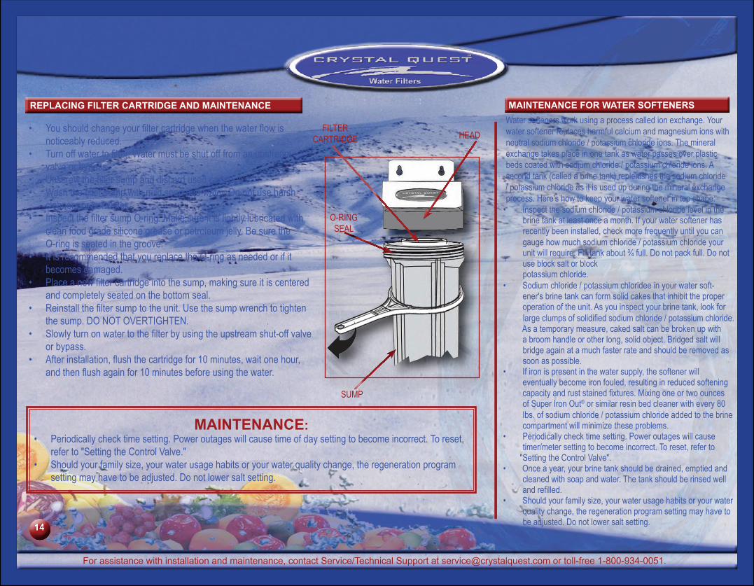
REPLACING FILTER CARTRIDGE AND mAINTENANCE mAINTENANCE FOR WATER SOFTENERSWater softeners work using a process called ion exchange. Your water softener replaces harmful calcium and magnesium ions with neutral sodium chloride / potassium chloride ions. The mineral exchange takes place in one tank as water passes over plastic beds coated with sodium chloride / potassium chloride ions. A second tank (called a brine tank) replenishes the sodium chloride / potassium chloride as it is used up during the mineral exchange process. Here's how to keep your water softener in top shape:
Inspect the • sodium chloride / potassium chloride level in the brine tank at least once a month. If your water softener has recently been installed, check more frequently until you can gauge how much sodium chloride / potassium chloride your unit will require. Fill tank about ¾ full. Do not pack full. Do not use block salt or block potassium chloride.Sodium chloride / potassium chloridee• in your water soft-ener's brine tank can form solid cakes that inhibit the proper operation of the unit. As you inspect your brine tank, look for largeclumpsofsolidifiedsodium chloride / potassium chloride. As a temporary measure, caked salt can be broken up with a broom handle or other long, solid object. Bridged salt will bridge again at a much faster rate and should be removed as soon as possible.If iron is present in the water supply, the softener will •eventually become iron fouled, resulting in reduced softening capacityandruststainedfixtures.Mixingoneortwoouncesof Super Iron Out® or similar resin bed cleaner with every 80 Ibs. of sodium chloride / potassium chloride added to the brine compartment will minimize these problems.Periodically check time setting. Power outages will cause •timer/meter setting to become incorrect. To reset, refer to
"Setting the Control Valve".Once a year, your brine tank should be drained, emptied and •cleaned with soap and water. The tank should be rinsed well andrefilled.Should your family size, your water usage habits or your water •quality change, the regeneration program setting may have to be adjusted. Do not lower salt setting.
mAINTENANCE:Periodically check time setting. Power outages will cause time of day setting to become incorrect. To reset, •refer to "Setting the Control Valve."Should your family size, your water usage habits or your water quality change, the regeneration program •setting may have to be adjusted. Do not lower salt setting.
FILTERCARTRIDGE HEAD
SUMP
O-RINGSEAL
Youshouldchangeyourfiltercartridgewhenthewaterflowis•noticeably reduced.Turnoffwatertofilter.Watermustbeshutofffromanupstream•valve or bypass.Unscrewthefiltersumpanddiscardusedcartridge.•Washthefiltersumpwithmildsoapandwater.Donotuseharsh•cleaners or hot water.InspectthefiltersumpO-ring.Makesureitislightlylubricatedwith•clean food grade silicone grease or petroleum jelly. Be sure the O-ring is seated in the groove.It is recommended that you replace the O-ring as needed or if it •becomes damaged.Placeanewfiltercartridgeintothesump,makingsureitiscentered•and completely seated on the bottom seal.Reinstallthefiltersumptotheunit.Usethesumpwrenchtotighten•thesump.DONOTOVERTIGHTEN.Slowlyturnonwatertothefilterbyusingtheupstreamshut-offvalve•or bypass.Afterinstallation,flushthecartridgefor10minutes,waitonehour,•andthenflushagainfor10minutesbeforeusingthewater.
For assistance with installation and maintenance, contact Service/Technical Support at [email protected] or toll-free 1-800-934-0051.
14
TROuBLESHOOTING
Problem Correction Water Filter SystemNOWATERFLOW 4 Re-read the instructions to install the system properly.•
Check the in and out arrows on the bypass valve to ensure the system is •not piped backwards.Make sure the bypass valve is in the "Service" position.•
Mechanical, Automatic, Water Softener or NitrateandTanninFilterSystems
MEDIADISCHARGINGDURINGBACKWASH/REGENERATION
4 Make sure top distributor has been installed properly.• Mechanical, Automatic, Water Softener or NitrateandTanninFilterSystems
4 Control valve not programmed properly. Check programming and •re-program as needed.Checkthewellfloatinthebrinetank.Thewellfloatshouldbeableto•move up and down, and the hose should be able to inject water into the tank and siphon it out again.
WaterSoftenerorNitrateandTanninFilterSystems
POORPERFORMANCE(FILTRATION/SOFTENINGABILITY)
4 Check the resin media level in the tank. System should be 2/3 full. •Check sodium chloride / potassium chloride level in brine tank. This •should be 3/4 full.Check the frequency and period of backwashing.•
Mechanical, Automatic, Water Softener or NitrateandTanninFilterSystems
SYSTEM USES TOO MUCH SODIUM CHLORIDE /POTASSIUMCHLORIDEANDEXCESSIVEWATERINBRINETANK
4 Brine draw not functioning. Clean injectors. Check and reset sodium •chloride / potassium chloride settings.
WaterSoftenerorNitrateandTanninFilterSystems
SOFTENERFAILSTOREGENERATE 4 Electricity to system has been interrupted.•Check the power source and programming of control valve.•
WaterSoftenerorNitrateandTanninFilterSystems
IRONBUILDUPINWATERCONDITIONERANDLOSS OF WATER PRESSURE
4 Clean control and add resin cleaner. Increase regeneration frequently.•Checkthepre-andpost-filtersfortimelyreplacement.•
WaterSoftenerorNitrateandTanninFilterSystems
INJECTORORINJECTORSCREENPLUGGED 4 Clean control and add resin cleaner. Increase regeneration frequently.• WaterSoftenerorNitrateandTanninFilterSystems
LEAKINDISTRIBUTORTUBE 4 Put the system in bypass position and depressurize* the unit by putting into "Backwash" position. There are 2 screws on neck of valve where the salt rinse line goes into softener. Remove the 2 screws and clean screen to remove any chunks of salt, etc.
WaterSoftenerorNitrateandTanninFilterSystems
*To depressurize, refer to control valve instructions.
To review the latest edition of the Installation and Operation Guide, visit www.crystalquest.com.
After prolonged periods of non-use (such as during a
vacation), it is recommended thatthesystembeflushedthoroughly.
First put the system in 1. bypass by turning the bypass valve to the "BYPASS" position. Let water run for 10-20 2. minutes by opening all faucetstoflushthepre-andpost-filtersandallwater supply lines.Turn handle on bypass 3. valve to "SERVICE" position to backwash* the system.
*Refer to manual for "Automatic/Mechanical Control Valve" to backwash the system.
15
ORDERING REPLACEmENT CARTRIDGES
To review the latest edition of the Installation and Operation Guide, visit www.crystalquest.com.
A TASTE OF NATURE ®
Your Purchase Information
Installation and Maintenance InstructionsKEEP THIS MANUAL FOR FUTURE
One-Year Limited WarrantyCRYSTAL QUEST® warrants your CRYSTAL QUEST® Point of Entry Whole House Water Filter System* for one year from the date of purchase against all defects in materials and workmanship when used in compliance with the manual. This warranty does not include replacement cartridges unless defective upon receipt. CRYSTAL
QUEST® disclaims all implied warranties including, without limitation, warranties of merchantability and fitness for a particular purpose. If for any reason the product proves
to be defective within one year from the date of purchase, please call for assistance. This warranty gives you specific legal rights and you may have other legal rights which vary from state
to state. CRYSTAL QUEST® assumes no responsibility for incidental or consequential damages, for damages arising out of misuse of the product, or the use of any unauthorized attachment. Some states do not allow the exclusion or limitation of implied warranties or incidental or consequential damages; therefore, the above limitations or exclusions may not apply to you. Should service be required during or after the warranty period or should you have any questions regarding how to use your CRYSTAL QUEST® Point of Entry Whole House Water Filter System, please contact our Technical Support Department at [email protected], Monday through Friday, 9 AM to 5 PM Eastern Time.
To order replacement cartridges or replacement media, contact your
Crystal Quest® Dealer or visit us online at http://www.crystalquest.com
Please record the information below for your future reference
Plumber’s Name Plumber’s Address Plumber’s Telephone